Article

Bainitic Transformation in 100Cr6 Steel for Bearing Balls: Effect on Fatigue Endurance

by
Paolo Matteis
1 and
Raffaella Sesana
2,*
1
Department of Applied Science and Technology (DISAT), Politecnico di Torino, Corso Duca degli Abruzzi 24, 10131 Torino, Italy
2
Department of Mechanical and Aerospace Engineering (DIMEAS), Politecnico di Torino, Corso Duca degli Abruzzi 24, 10131 Torino, Italy
*
Author to whom correspondence should be addressed.
Metals 2025, 15(9), 931; https://doi.org/10.3390/met15090931
Submission received: 17 June 2025 / Revised: 12 August 2025 / Accepted: 16 August 2025 / Published: 22 August 2025
(This article belongs to the Special Issue Recent Advances in High-Performance Steel)

Abstract

A set of bearing balls, fabricated with grade 100Cr6 bearing steel, was subjected either to ordinary quenching and tempering final heat treatment (leading to a mainly tempered martensitic microstructure) or to an alternative heat treatment (leading to a mainly bainitic microstructure). In order to compare their final properties and service performance, the balls were then subjected to rolling contact fatigue tests, as well as to other metallurgical and mechanical characterizations. Further mechanical tests, including tensile tests and rotating bending fatigue tests, were also performed on test specimens made with the same material and subjected to the same final heat treatments. The bainitic material, compared to the tempered martensitic one, exhibited a slightly better performance in the rotating bending fatigue tests, but not in the rolling contact fatigue tests.

1. Introduction

Bearing balls are commonly made from the spheroidized annealed 100Cr6 steel rods by means of the following steps: cutting; cold forming; preliminary grinding; austenitizing, quenching, and low-temperature tempering; peening (the balls hit each other in a rotating drum); final grinding; and several polishing steps. Materials used for bearing applications undergo strict requirements related to high static and fatigue resistance, rolling contact fatigue (RCF) resistance, wear and corrosion resistance, dimensional stability, and thermomechanical stability. The most widely used material for rolling bearings is SAE 52100 (100Cr6) steel, a high-carbon quenching steel. In order to have a high-quality product with high performance, it is essential that the material is characterized by a high degree of purity, which means a very low quantity of non-metallic inclusions and a homogeneous distribution of carbides in the metal matrix: experience and several studies have shown that rolling bearing life is strongly influenced by these aspects [1]. The bearing components are obtained both from well-selected starting materials and by careful processing, in order to obtain high mechanical properties, especially with regard to RCF resistance, as well as to chemical agents and temperatures in the case of special applications [2]. The most critical components from the point of view of manufacturing and quality control in the rolling-body bearing are the balls [3].
Heat treatment is responsible for the phase transformation of high-carbon bainitic steel for bearing applications. In [4], a detailed investigation of the phase transformation of the steel under slow cooling was carried out. The results show that austenitizing involves ferrite transforming into austenite and cementite dissolution. The bainitic transformation, occurring at lower temperatures, involves the formation of bainitic ferrite and retained austenite, with variations in the morphology and distribution of these phases. The bainitic transformation behavior can vary depending on the sample size and geometry. Dislocations play a crucial role in bainitic transformation, with their movement and recovery influencing the nucleation and growth of bainitic ferrite. Furthermore, the precipitation of intermetallic phases and carbides can also influence the bainitic transformation and the resulting microstructure. In [5], the residual stress and friction properties of Cr-Mo-V alloyed M50 bearing steel are analyzed after austempering. Wear resistance of the sample increases with the austempering time, which is mainly related to hardness, residual stress state, and thermal stability. The effect of austempering on impact toughness and tensile strength of Nb/V microalloyed bainitic bearing steel is analyzed in [6]. Austempering Nb/V microalloyed bainitic bearing steel significantly impacts its mechanical properties, as it increases both strength and toughness due to the formation of a bainitic microstructure. The specific properties are highly dependent on the austempering temperature and time, with increased temperature generally leading to lower hardness and increased impact toughness. The addition of Nb and V, as well as the austempering process, refines the grain size and improves the stability of retained austenite, thereby enhancing the steel’s mechanical performance.
Cold rolling, which is used as a forming method for bearing rings, also influences the development of microstructures during subsequent heat treatments. In [7], this aspect is investigated for M50 bearing steel when subjected to austempering. Cold rolling induces dislocations, and the dislocation density increases. Carbide dissolution is increased along with carbon content, the bainite incubation time is shortened, and the bainite sheaf width is limited. A kinetic model is also validated by describing bainite nucleation due to cold rolling.
A similar study is reported in [8], where the influence of pre-cold deformation treatments on nano-bainite transformation is investigated for GCr15Si1Mo (similar to 100Cr6, but with additional 1% Si). This research confirms the role of the cold deformation process in promoting nano bainite transformation, decreasing the size of austenite grains, and uniforming the size of carbides. And by reducing the thickness of bainitic ferrite plates, both hardness and toughness increase.
Concerning the influence of bainitic structure on mechanical behavior in a typical bearing application, that is, RCF, a large number of studies in the literature are available. Among the most recent studies, in [9], the RCF behavior of 7NbMo, a microalloyed steel for railway wheels, is experimentally investigated. The steel presents microstructures of upper bainite (UB—350 HV0.5), lower bainite (LB—450 HV0.5), and pearlite (PE—350 HV0.5). Lower and upper bainite showed higher wear resistance when compared to pearlite, and the main wear mechanism for the three microstructures is fatigue wear. Damaged sections showed greater resistance to RCF in bainitic microstructures than in pearlite ones. The morphological arrangement of the microstructure of bainite increases mechanical properties and develops a higher ductility per unit volume. In [10], a similar study on C70 railway steel and a bainitic steel is presented. It was found that the improved RCF and wear resistance of the microstructure can be attributed to the combined effect of strength and toughness, larger plastic strain accumulation, and lower fatigue damage. The RCF damage mechanism in railway steel is also investigated in [11,12], with similar findings. In [13], RCF is investigated on a carbide-free nanostructured bainitic bearing steel. The degradation mechanism was shown to be different from a typical damage mechanism in bearing: ductile void formation at interfaces and growth and coalescence into larger voids lead to fracture in the direction of the softer phase, with crack initiation at inclusions and propagation. A similar analysis is described in [14] for bainitic steels with and without residual cementite.
A critical issue when dealing with the microstructure of bearing components, and in particular of rolling bodies, is dimensional stability. Dimensional stability of a sphere means its ability to maintain its size unchanged during its life cycle. Dimensional variations can lead to redistribution of the loads, to acceleration of the degradation process of the ball, and to a shorter life of the bearing [15]. A fundamental role in dimensional stability is played by the amount of residual austenite in the sphere steel: in the presence of thermomechanical stresses, which may occur in particular operating conditions, this metastable phase can decompose into other phases and other microstructural constituents, which are characterized by different specific volumes. Residual austenite can assume two different morphologies: blocky and thin film. The first is unstable, while the second is very fine and stable by virtue of the carbon enrichment [16,17], making it more suitable for bearing applications. A significant study [18] confirms the role of bainite in providing mechanical requirements for bearing steel.
In the present work, a study was carried out to evaluate the effects of two different heat treatments, and therefore of two different microstructures, on the mechanical properties of the steel, on the dimensional stability of the spheres, and on their durability, when extreme Hertzian-contact fatigue is present. The aim of this study is to investigate alternative thermal and mechanical processing of 100Cr6 to obtain comparable mechanical properties for commercial bearing rolling body manufacturing. In particular, a bainitic quenching heat treatment is compared with standard quenching and tempering (martensitic) heat treatment.

2. Materials and Methods

2.1. Overview

Two test campaigns were designed.
The first was run on cylindrical samples, consisting of tensile, Charpy-V, and rotating bending fatigue tests. The aim of this test campaign was to characterize material properties related to different thermal treatments. The second test campaign consisted of RCF in simulated operating conditions, and it was run on rolling balls by means of a dedicated test rig. The aim of this test campaign was to investigate the effect of multiaxial fatigue stresses in operating conditions.
The microstructure, hardness, and residual stress state were also examined in all sets of samples. Moreover, dimensional measurement analysis of balls was performed to quantify dimensional stability for the two different thermal treatments.
In order to evaluate the influence of the two different heat treatments on the dimensional stability of the spheres (nominal diameter 10.500 mm), the following experimental procedure was performed:
  • Determination of the average percentage of residual austenite on 10 new spheres, 5 subjected to standard heat treatment and 5 subjected to bainitic hardening treatment. Measurement was carried out using an X-ray diffraction technique with a diffractometer, according to ASTM E975 standard [19].
  • Measurement of the average diameter Dwm1 of each new sphere for a total of 20 spheres; 10 consisted of tempered martensite and 10 consisted of bainite, with an accuracy of 0.1 μm. Detection was carried out using a comparator in a temperature-controlled chamber and following a procedure that minimizes the effects of any thermal expansion on the measurement.
  • Tempering of the 20 spheres mentioned above at a temperature of 235 °C ± 2 °C for a period of 4 h in atmospheric air.
  • Measurement of the average diameter Dwm2 of each tempered sphere using a procedure completely similar to the one described previously.
  • Evaluation of the variation in size of each sphere using the following relationship:
    δ = D w m 2 D w m 1 D w m 1

2.2. Materials and Specimens

All test specimens were obtained from 3 nominally equal lots of annealed 100Cr6 steel rods, with the original diameter equal to 8 mm. The elemental composition of the steel was measured via atomic emission spectroscopy, with spark excitation on one lot, and is reported Table 1.
Two sets of cylindrical samples and two sets of balls were obtained.
The same type of cylindrical test specimens was employed for both the tensile tests and the rotating bending fatigue tests. Cylindrical smooth specimens were designed according to ISO 1143 Standard Practice [20]. These specimen were machined from the steel rods, heat-treated as described here below, and ground. A total of 6 tensile testing specimens and 30 rotating bending fatigue specimens were machined. The specimen design is reported in Figure 1. The calibrated diameter and length of the cylindrical specimens were 4.5 and 24 mm, respectively, and their surface roughness (Ra) was about 0.04 µm.
Owing to their size, the specimens for the Charpy test were fabricated from a different lot of steel rod, of nominally equal composition, but with an original diameter of 16 mm. The length and the V notch of the Charpy specimens were consistent with the ISO 148-1 International standard [21], but their full cross-section was smaller and equal to 8 × 8 mm. A total of 3 specimens were obtained with a martensitic microstructure, and 3 were obtained with a bainitic microstructure.
The overall production process employed to fabricate the bearing balls, starting with the annealed rods, was consistent with the above-mentioned industrial manufacturing procedure [22], the only difference being the heat treatment, which is described below. The final diameter of the bearing balls was 10.5 mm, and their surface roughness (Ra) was less than 0.02 µm.
One-half of the specimens the balls underwent the standard quenching and tempering process, while the other samples were processed to obtain a bainitic structure.
The experimental bainitic heat treatment consisted of austenitizing at 860 °C for 65 min, then quenching in a salt bath at 250 °C for 35 min. The standard martensitic heat treatment consisted of austenitizing at about 840 °C for about 15 min, quenching in oil, and tempering at 150 °C for 2 h; the balls and the specimens were austenitized at slightly different temperatures. The heat treatments are described in detail in Table 2 and Table 3.
The parameters used for tempered martensite are those currently in production. For bainitic heat treatment, the austenitization temperature was slightly higher than in the previous case (quenched and tempered) to dissolve more carbides and introduce more carbon into the solution, thus improving hardness. However, this is not too high to prevent austenitic grain growth and avoid the risk of excessive residual austenite, which reduces hardness. The bainitic transformation temperature was quite low, 250 °C, just above Ms, which is approximately 210–220 °C. This was for the same reason as above—that is, to recover some hardness, so as to have hardness and strength characteristics not much lower than tempered martensite.

2.3. Mechanical Testing

Tensile tests were run on an MTS universal testing machine (MTS Systems, Eden Prairie, MN, USA) (load cell of 250 kN, extensometer MTS n. 634.12F-24) according to ISO 6892-1: 2019 Standard [23].
Then, four-point rotating bending fatigue tests were run on an Italsigma RB35 machine (Italsigma, srl, Forlì (FC), Italy) according to ISO 1143-1: 2010 Standard [20]. The staircase method was used to estimate the 5 million cycle fatigue strength σD-1 of steel, as indicated by ISO 12107: 2012 Standard [24]. The stress range increment was set at 25 MPa, and the rotating speed was set at 3500 rpm.
The Charpy tests were performed in the DISAT labs at room temperature, according to ISO 148 International Standard [21].
The rolling fatigue tests on balls were carried out at the Central Laboratory in TN, Italy. Test benches were used for this purpose, which are capable of loading the balls with purely axial loads. A detailed description of the operation of the test system is given in [25], and a scheme of the testing equipment is shown in Figure 2. Each test bench consists of a shaft supported by a pair of oblique bearings mounted on opposite sides of a central shoulder. The two used bearings are SKF HUB ACBB (two crowns of 14 balls each; a diameter of 11.112 mm) and SKF HUB ACBB (two crowns of 15 balls each; a diameter of 10.500 mm). To increase the contact pressure between the rings and ball tracks tested, a single ring bearing consisting of 5 tested balls with a diameter of 10.500 mm was inserted into the bearing; a ball bearing with a diameter of 11.112 mm was fitted with a single complete ring. The test bearing was equipped with acceleration and temperature transducers to detect ball failure.
The applied axial load was P = 20,500 N in all tests. By considering the number of balls and the geometry of the bearing, the normal load on each ball was 2096 N, and by considering local curvature radii and the elastic properties of the material, according to the Hertz theory, the maximum equivalent contact stress was 3420 MPa. Eight tests were carried out for each of the two groups of spheres. After assembly, the load was maintained at 30% of the maximum value for 10 mins to promote a homogeneous distribution of lubricant and shaft alignment; after this time, the axial load reached the test value. During the test, the load was released every 5 min for a period of 25 s in order to facilitate a variation of the axis of rotation of the balls and to present more uniform fatigue damage on their surfaces. Every 20 h, the test was interrupted to disassemble the bench; clean; and complete an inspection of the tested balls in terms of ovalization and mass to assess the state of damage, inversion, or replacement (if both sides had already been used) of the rings of both bearings, as well as replace the untested balls. After lubrication and assembly, the test restarted according to the first start. Each test was considered completed when either vibrations exceeded 15 mm2/s or the temperature exceeded 145 °C; a sign of failure of one or more tested balls occurred; or the maximum test duration of 200 h was reached. In tests with a duration of less than 200 h, a stop occurred due to excessive vibrations caused by the rupture of one ball. In Test 6 on bainite balls, two balls failed. In tests with a duration longer than 200 h, no significant sign of failure on the surface of balls was observed. The gross test duration of 200 h corresponded to a net duration of 183.1 h after subtracting the duration of the low-load and no-load periods. At the end of each test, the broken spheres were inspected with a stereomicroscope. Then, metallographic samples of test balls with different durations were prepared, and their microstructure was observed under an optical microscope to capture the microstructural transformations induced by the wearing Hertzian loads. Moreover, the evolution of surface hardness was monitored.

3. Results and Discussion

3.1. Microstructure

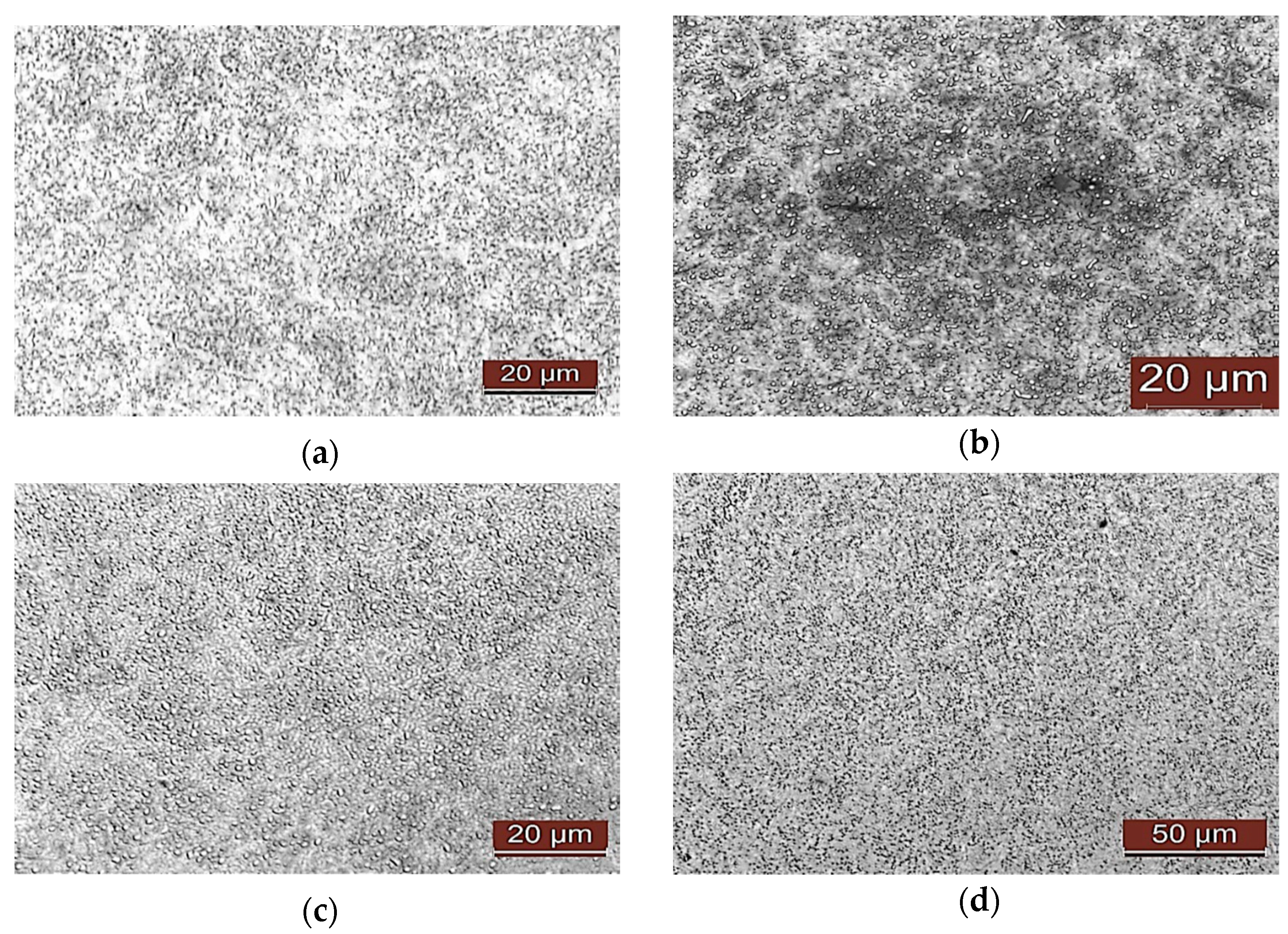
The ensuing bainitic and tempered martensitic microstructures were examined via standard optical metallography, with Nital etching, and are shown in Figure 3.
Moreover, by means of X-ray diffraction (XRD) analysis, it was found that the fraction of retained austenite was about 10% in the tempered martensitic microstructure and about 4% in the bainitic microstructure. In order to evaluate the stability of the retained austenite, some specimens were heated at 235 °C for 4 h; after this heat treatment, further XRD analyses showed that, in the tempered martensitic material, the prior retained austenite was fully transformed, whereas in the bainitic material, the amount of retained austenite was unmodified. This result is attributed to a greater content of carbon in the retained austenite in the bainite case, arising from the carbon partition, which occurs during the bainitic transformation.

3.2. Tensile Testing

In Figure 4, the strain–stress curves for a bainitic specimen and a martensitic specimen are reported as an example; the initial part of each curve was obtained with an extensometer, whereas the final part was estimated by using the actuator displacement signal. In Table 4, the static mechanical properties of the two materials are reported. The resulting monotonic mechanical properties confirm the potential of these bainitic steels for ball bearing applications. The rather small elongation of Martensitic 1, reported in Table 4, could be caused by an internal defect or inclusion, together with the great sensitivity to defects of this material, which are very hard and not very tough. These defects can be present in standard 100Cr6, as reported in [25]. In Figure 5, the fracture surfaces of a bainitic tensile specimen and a martensitic tensile specimen are reported as examples.
It emerged that the average elongation at failure of the bainitic specimens shows a reduction of about 10% compared to the martensite specimens; the yield strength of the two groups of specimens is almost identical, with a reduction of 1.5% in the bainitic sample compared to the martensitic sample. The ultimate tensile strength of the bainitic specimens showed a reduction of 10% compared to the martensitic specimens; the modulus of elasticity of the two groups of specimens was equal, although lower than the typical values of construction steels. These results are confirmed by what is reported in the scientific literature on the sector [25,26,27,28,29]. The data obtained clearly show that the bainitic specimens are characterized by a lower strength and a lower elongation at failure compared to those in tempered martensite.

3.3. Chrapy Tests

The results related to Charpy tests are reported in Table 5.
The comparison of the results shows a 75% increase in the impact strength of the bainitic specimens compared to martensitic specimens. It can therefore be stated that bainite allows the material to absorb a greater impact energy, although, in absolute terms, the impact strength values obtained are very low when compared to other types of steel. Moreover, it is known that, as the carbon content increases, at the same temperature, the capacity of the steel to absorb impact energy decreases, and this also denotes a lower ductility. The results obtained are confirmed by the literature [30,31,32], even if the reported values concern specimens of different shapes and dimensions; in particular, in [31], reference is made to specimens with a V-shaped notch and with a square cross-section of side equal to 10 mm, while in [24], reference is made to unnotched cylindrical specimens with a diameter equal to 10 mm.

3.4. Rotating Bending Fatigue Tests

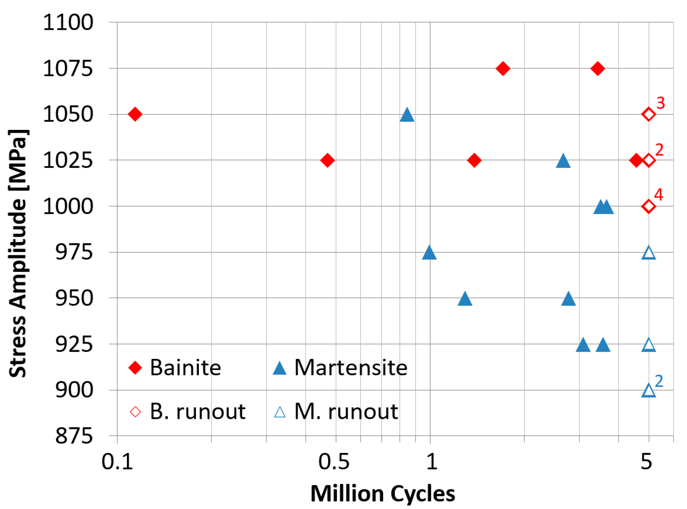
In Figure 6, the rotating bending fatigue testing results are summarized for a stress ratio R = −1. The run-out specimens are reported with empty symbols, and the numbers indicate the corresponding quantity of run-out specimens (3 for 1050 MPa, 2 for 1025 MPa, 4 for 1000 MPa, and 2 for 900 MPa). The fatigue strength at 5 million cycles is 1033 MPa for bainitic samples and 913 MPa for tempered martensitic samples based on the staircase method [24].
Unlike tensile test results, the bainitic specimens show higher fatigue resistance properties by about 13.1%. Bainitic specimens also show a lower statistical dispersion of fatigue data. Crack nucleation occurred due to subsurface non-metallic inclusions or a surface defect. Fish-eye structures can be observed in proximity to the inclusion or defect.
In Figure 7, some failure surfaces are reported as examples. The literature reports numerous experimental campaigns run in order to characterize the material; the many available data, however, were obtained with different fatigue test configurations (tensile–compression tests, torsion tests, and alternate bending tests), and different heat treatments. For example, observing the data in [28] relating to specimens with a bainitic microstructure and those in [29] relating to specimens with a tempered martensitic microstructure, with reference to the interval of cycles reported in Figure 6, there is no relation with respect to fatigue resistance, even if the orders of magnitude are the same.

3.5. Ball Dimensional Stability

In Table 6, the measurements of residual austenite and the corresponding decrement, before and after tempering, for martensitic and bainitic balls are reported. In Table 7, the measured dimensional variation for martensitic and bainitic balls is reported.
The martensitic balls contain a larger quantity of residual austenite than bainitic ones: the bainitic hardening process favors the dissolution of the austenitic phase in favor of the formation of cementite and ferrite plates, which characterize the bainitic microstructure; at the same time, the remaining austenite is enriched in carbon, becoming more stable. Martensitic balls are also characterized by a considerable reduction in residual austenite after tempering, with a decrease of 10.5% and a final value close to zero. Bainitic spheres, on the other hand, have an austenite variation of 0.2%, which is quite negligible when compared to that of the other type of spheres.
The standard spheres showed a large variation in residual austenite, meaning that they were subject to more significant dimensional variations than those of the bainite spheres, as confirmed in Table 7. The martensitic balls showed greater dimensional variation and lower dimensional stability than bainitic balls.
The different behavior of austenite in the two groups of spheres may be due to the prevalence of one of the two morphologies and a different carbon concentration (the higher the percentage of carbon dissolved in the austenitic matrix, the more stable the austenite itself).
In [16], a detailed study of the microstructural phenomena responsible for the dimensional variations is presented; other factors affect the dimensional stability. Regarding the martensitic microstructure, considering the heat treatment at 235 °C, the microstructural transformations are divided into two phases:
  • Phase A, in which ε-carbides are precipitated and the amount of carbon present in the martensitic matrix is reduced. The formation of carbides leads to expansion, while the reduction in the martensitic matrix leads to a contraction of greater amplitude; the overall effect is a contraction in volume.
  • Phase B, in which there is decomposition of residual austenite and the formation of cementite carbides to the detriment of ε carbides; in this case, the two processes involve an expansion, and the overall effect is a volume expansion.
After the two phases, a volumetric expansion of the component is obtained, as evidenced by the tests. In the case of bainitic microstructure, due to the greater stability of the residual austenite, only a small percentage of it decomposes, and this is accompanied by the transformation of the nanometric particles of cementite into larger carbides. These two processes result in a volume expansion of the material, albeit minor, as can also be seen in the experimental data shown in Table 7.

3.6. Rolling Contact Fatigue

In a rolling bearing, both the rolling bodies and the ring tracks undergo RCF, a fatigue phenomenon due to the Hertzian contact stresses under cyclic compressive loading.
Experience has shown that failure mainly occurs in ring tracks rather than rolling bodies. Bearing life is thus related to the applied load and the number of passes. The frequency of contact on a general point of the ring tracks can be determined as a function of the speed of rotation of the bearing and its geometry; the same cannot be said for points on the surface of the balls, because they generally have a rotational motion that is composed of rolling and precession.
The two main mechanisms of fatigue damage of a bearing are surface chipping and spalling. During operation of the bearing, microstructural changes occur in the material, modifying the rolling bodies and the ring tracks in response to fatigue cycles. These variations, of which very detailed studies are available in the technical literature, involve different mechanisms, and an increase in yield point and a redistribution of residual stress are observed due to the reduction in residual austenite in favor of the formation of other phases, including martensite.
The number of fatigue cycles can be obtained from duration, for the bearing (Nb) or the single ball (Nn, Nominal ball fatigue cycles). Regarding the spheres, it is necessary to take into account the rolling, spinning, and precession motions of the balls in the bearing. A detailed description of these calculations is reported in [33]. In order to calculate the number of cycles for balls, two scenarios can then be considered: the motion of the balls is pure rolling (Nn), or rolling, spinning, and precession are taken into account (Nc, calculated ball fatigue cycles). Nn is calculated according to kinematic considerations [33], while for Nc, a description is provided in [34] and in general in [33]. In both cases, in a complete rotation of the ball, two load cycles take place: contact with the internal track and contact with the external track.
These experimental results and corresponding calculations are reported in Table 8.
In Table 8, it can be seen that the standard spheres showed higher gross durations than the bainite spheres, with an average value 77.9% higher. Regarding the life values of the test campaigns, the base durations obtained were L10h = 121.2 h for martensitic balls and L10h = 32.4 h for bainitic balls.
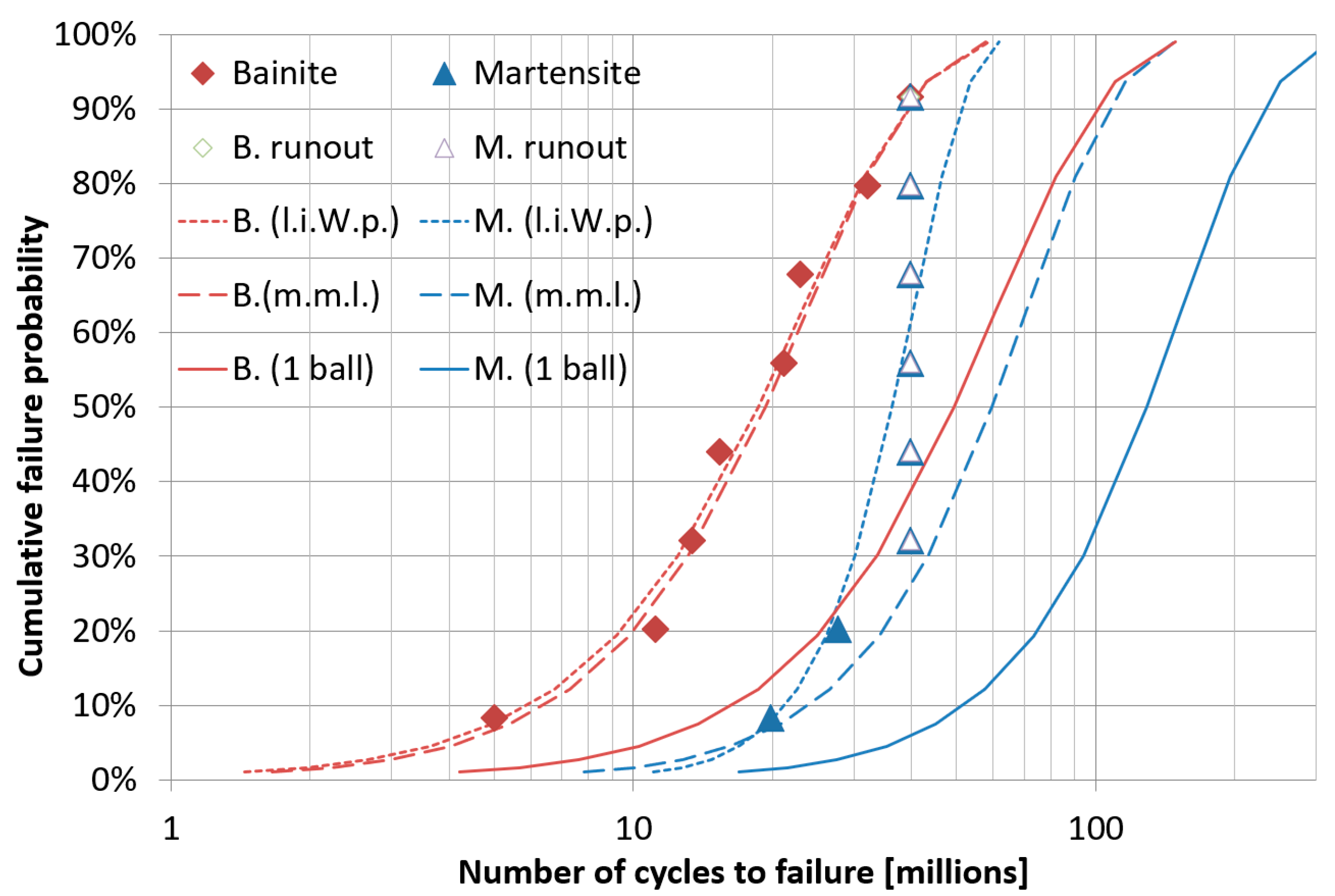
Figure 8 shows the estimated cumulative failure probability of the five-ball sets, formed with either bainitic or tempered martensitic balls, as determined from the experimental data by assuming that the underlying failure probability distribution is a Weibull distribution and by either performing a linear interpolation of the Weibull plot or by using the maximum likelihood method. The estimated cumulative failure probability of a single bainitic or tempered martensitic ball, as deduced from the same data using the maximum likelihood method, is also shown. It is important to note that the failure probability of the set of five balls is always much greater than the failure probability of a single ball, because the failure of any of the five balls implies the failure of the set. The line obtained using the maximum likelihood method for martensitic steel appears to be shifted to the right, as, in this group of tests, many run-outs occurred. The run-out samples survived, but if the test had continued until failure, the same points would be further to the right. The maximum likelihood calculation takes into account the fact that these samples survived. Some points, related to run-outs, were represented in arbitrary positions to point out the higher number of run-outs for this material.
In Table 9, the results of hardness HV2 measurements are reported. In particular, the HV ratio is calculated as the ratio between the HV2 of the ball after RCF testing and the HV2 of a new ball, without RCF damage, in %.
The fatigue endurance of the bearing balls in the rolling contact fatigue test is greater than the fatigue endurance of the same materials in the rotating bending fatigue test, even if the maximum stress is higher in the former case. This is mainly attributed to the variable loading cycle, which occurs in the rolling contact fatigue test, whereby each material point undergoes the most severe loading only for a small fraction of the total number of cycles. The lower performance of the bainitic steel in the RCF tests, as opposed to the rotating bending fatigue (RBF) ones, may be justified by the lower plastic flow stress of bainitic steel, which may be more relevant in the RCF, because the maximum stress is higher. The different results in these two types of tests can, in general, be ascribed to the different loading conditions, including the periodic variation of the load cycle, multiaxial loading, and greater compressive stresses, which occur in the RCF tests.
The reasons for this difference in durability between the two groups of balls could also be the different surface hardness between the material constituting the balls and that of the bearing tracks: in the former case, the surface hardness would have played a role in favor of durability, in the latter case, it would have played an unfavorable role.
In both cases, however, there was a reduction in the surface hardness as the number of hours of operation increased, compared to that of the untested sphere; this reduction is a consequence of phase transformations that take place at the microstructural level (described above) and phase transformations induced by the loading conditions. Furthermore, cyclic loading also involves wear damage of the spheres, as evidenced by the decrease in their mass. Further, in [35,36], it is reported that, in bainitic and martensitic microstructures, hardness is a crucial factor influencing fatigue behavior. Higher hardness generally leads to increased strength and wear resistance, but it can also make the material more susceptible to brittle fracture and reduce its fatigue life. Hardness generally has a positive influence on fatigue life, and harder materials tend to exhibit longer fatigue lives. This is because higher hardness often correlates with increased strength and resistance to plastic deformation, which are crucial factors in resisting crack initiation and propagation during cyclic loading. While hardness can hinder crack initiation, once a crack has formed, the material’s resistance to crack propagation becomes more critical. In some cases, harder materials may be more susceptible to brittle fracture once a crack has initiated.
The data shown in Table 9 confirm that the surface hardness of bainitic balls is lower than that of martensitic balls.
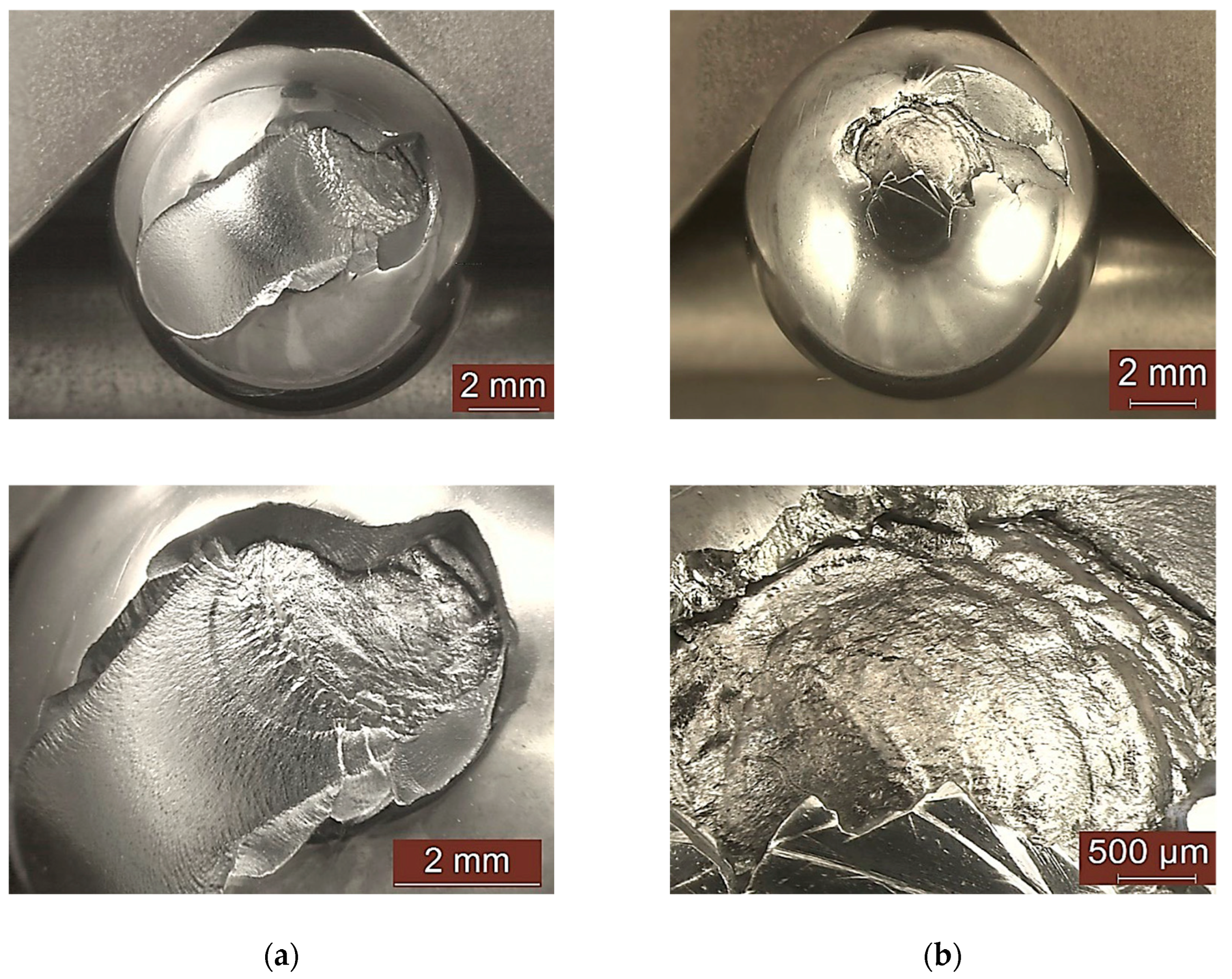
In all tests with a life less than 200 h, at least one sphere failed due to surface splitting with a crack, which originated from an inclusion in a subsurface position, according to [25]. Some examples of balls with spalling marks are given in Figure 9 for both microstructures. Failure occurs when small fragments are formed due to subsurface cracks. Cracks show beach marks, which confirm a variable loading condition.
Microstructural analysis showed, in both types of balls, the typical variations associated with the phenomenon of fatigue from Hertzian contact: the development of a Dark Etching Region (DER), the formation of White Etching Bands (WEBs), and, in some cases, butterfly wings were identified [34]. Some of the images obtained using the optical microscope are shown. Some examples are given in Figure 10 for a martensitic ball, and some are shown in Figure 11 for a bainitic ball.

4. Conclusions

In this study, a bainitic quenching heat treatment is compared with standard quenching and tempering (martensitic) heat treatment to produce bearing balls.
The martensitic microstructure exhibits approximately 10% retained austenite, which can be easily transformed; the bainitic microstructure exhibits approximately 4% austenite, which is more stable.
Both materials exhibit high strength, low ductility, and brittle behavior in tensile and Charpy-V tests.
The bainitic steel, as opposed to the martensitic one, exhibits the following properties:
  • Lower strength (approximately 2300 vs. 2600 MPa) and hardness (approximately 680 vs. 750 HV);
  • Near-equal tensile elongation (approximately 5%) and higher Charpy V impact energy (approximately 5 vs. 3 J with subsized specimens).
In the rotating bending fatigue test, bainitic steel offers a significant improvement (approximately 1030 vs. 910 MPa fatigue strength at 5 million cycles). Cracks nucleate from subsurface defects and propagate continuously through the specimen cross-section.
In the RCF test, bainitic steel balls show the worst performance, with 50% survival probability at approximately 20 Mcycles vs. 60 Mcycles for the martensitic steel (for a set of five balls). Failure occurs when small fragments are formed due to subsurface cracks. Cracks show beach marks, which confirm a variable loading condition.
The fatigue endurance of the bearing balls in the RCF test is greater than the fatigue endurance of the same materials in the rotating bending fatigue test, even if the maximum stress is higher in the former case. This is attributed mainly to the variable loading cycle that occurs in the RCF test, whereby each material point undergoes the most severe loading only for a small fraction of the total number of cycles.
The reduced performance of the bainitic steel in the RCF tests, as opposed to the rotating bending fatigue tests, may be justified by its lower plastic flow stress, which may be more relevant in the RCF because the maximum stress is higher.
The different results in these two types of tests can, in general, be ascribed to the different loading conditions, including the periodic variation of the load cycle, multiaxial loading, and greater compressive stresses that occur in the RCF tests.

Author Contributions

Conceptualization, P.M. and R.S.; methodology, P.M.; validation, P.M. and R.S.; formal analysis, R.S.; investigation, P.M.; resources, R.S.; data curation, P.M. and R.S.; writing—original draft preparation, P.M. and R.S.; writing—review and editing, P.M. and R.S.; supervision, P.M.; project administration, R.S. All authors have read and agreed to the published version of the manuscript.

Funding

This research received no external funding.

Data Availability Statement

The original contributions presented in this study are included in the article. Further inquiries can be directed to the corresponding author.

Conflicts of Interest

The authors declare no conflicts of interest.

References

  1. Zaretsky, E.V. Rolling Bearing Life Prediction, Theory, and Application; NASA/TP—2013-215305; NASA: Washington, DC, USA, 1 March 2013. [Google Scholar]
  2. Ioannides, T.A.; Harris, E.; Ragen, M. Endurance of aircraft gas turbine mainshaft ball bearings—Analysis using improved fatigue life theory: Part I—Application to a Long-Life Bearing. J. Tribol. 1990, 112, 304–308. [Google Scholar] [CrossRef]
  3. Raj, K.K.; Kumar, S.; Kumar, R.R. Systematic Review of Bearing Component Failure: Strategies for Diagnosis and Prognosis in Rotating Machinery. Arab. J. Sci. Eng. 2025, 50, 5353–5375. [Google Scholar] [CrossRef]
  4. Sun, D.; Zhao, J.; Zhang, M.; Fang, Q.; Long, X.; Zhang, F.; Yang, Z. In-situ observation of phase transformation during heat treatment process of high-carbon bainitic bearing steel. J. Mater. Res. Technol. 2022, 19, 3713–3723. [Google Scholar] [CrossRef]
  5. Yu, X.F.; Wei, Y.H.; Zheng, D.Y.; Shen, X.Y.; Su, Y.; Xia, Y.Z.; Liu, Y.B. Effect of nano-bainite microstructure and residual stress on friction properties of M50 bearing steel. Tribol. Int. 2022, 165, 107285. [Google Scholar] [CrossRef]
  6. Wang, Y.; Liu, B.; Pan, Q.; Zhao, J.; Zhao, X.; Sun, H.; Xu, D.; Yang, Z. Effect of Austempering on Mechanical Properties of Nb/V Microalloyed Bainitic Bearing Steel. Crystals 2022, 12, 1001. [Google Scholar] [CrossRef]
  7. Hua, L.; Du, Y.; Qian, D.; Sun, M.; Wang, F. Influence of Prior Cold Rolling on Bainite Transformation of High Carbon Bearing Steel. Mater. Sci. Eng. A 2025, 56, 640–654. [Google Scholar]
  8. Jia, D.; Zhang, C.; Wang, Q.; Wang, H.; Yang, Z.; Zhang, F. Unleashing the potential of nano-bainite bearing steels: Controllable selection of microstructure evolution enables concurrent improvement of toughness and hardness by pre-cold deformation. Mater. Sci. Eng. A 2024, 906, 146715. [Google Scholar] [CrossRef]
  9. Miranda, R.S.; Rezende, A.B.; Carvalho, A.C.; Fonseca, S.T.; Sinatora, A.; Mei, P.R. The role of microstructure on the wear and rolling contact fatigue of railway steels: The performance of bainite. Wear 2024, 548–549, 205398. [Google Scholar] [CrossRef]
  10. Fan, Y.; Gui, X.; Liu, M.; Wang, X.; Bai, B.; Gao, G. Effect of microstructure on wear and rolling contact fatigue behaviors of bainitic/martensitic rail steels. Wear 2022, 508–509, 204474. [Google Scholar] [CrossRef]
  11. Li, Q.; Huang, X.; Huang, W. Fatigue property and microstructure deformation behaviour of multiphase microstructure in a medium-carbon bainite steel under rolling contact condition. Int. J. Fatigue 2019, 125, 381–393. [Google Scholar] [CrossRef]
  12. Ruijie, Z.; Chunlei, Z.; Bo, L.; Xubiao, W.; Xiaofeng, L.; Yanguo, L.; Fucheng, Z. Research progress on rolling contact fatigue damage of bainitic rail steel. Eng. Fail. Anal. 2023, 143, 106875. [Google Scholar] [CrossRef]
  13. Solano-Alvarez, W.; Pickering, E.J.; Bhadeshia, H.K.D.H. Degradation of nanostructured bainitic steel under rolling contact fatigue. Mater. Sci. Eng. A 2014, 617, 156–164. [Google Scholar] [CrossRef]
  14. Qin, Y.-M.; Liu, C.-B.; Zhang, C.-S.; Wang, X.-B.; Long, X.-Y.; Li, Y.-G.; Yang, Z.-N.; Zhang, F.-C. Comparison on wear resistance of nanostructured bainitic bearing steel with and without residual cementite. J. Iron Steel Res. Int. 2022, 29, 339–349. [Google Scholar] [CrossRef]
  15. Podder, A.S.; Bhadeshia, H. Thermal stability of austenite retained in bainitic steels. Mater. Sci. Eng. A 2010, 527, 2121–2128. [Google Scholar] [CrossRef]
  16. Sidoroff, C.; Perez, M.; Dierickx, P.; Girodin, D. Advantages and Shortcomings of Retained Austenite in Bearing Steels: A Review. Bear. Steel Technol. 2015, 10, 312–348. [Google Scholar] [CrossRef]
  17. Yang, Z.N.; Ji, Y.L.; Zhang, F.C.; Zhang, M.; Nawaz, B.; Zheng, C.L. Microstructural evolution and performance change of a carburized nanostructured bainitic bearing steel during rolling contact fatigue process. Mater. Sci. Eng. A 2018, 725, 98–107. [Google Scholar] [CrossRef]
  18. Fu, H.; Song, W.; Galindo-Nava, E.I.; Rivera-Díaz-del-Castillo, P.E. Strain-induced martensite decay in bearing steels under rolling contact fatigue: Modelling and atomic-scale characterisation. Acta Mater. 2017, 139, 163–173. [Google Scholar] [CrossRef]
  19. ASTM E975-22; Standard Practice for X-Ray Determination of Retained Austenite in Steel with Near Random Crystallographic Orientation. ASTM International: Conshohocken, PA, USA, 2022.
  20. ISO 1143:2010; Metallic Materials—Rotating Bar Bending Fatigue Testing. ISO: Geneva, Switzerland, 2010.
  21. ISO 148-1:2016; Metallic Materials—Charpy Pendulum Impact Test, Part 1: Test Method. ISO: Geneva, Switzerland, 2016.
  22. Kalpakjian, S.; Schmid, S.R. Manufacturing and Engineering and Technology, 7th ed.; Pearson Education Ltd.: London, UK, 2014. [Google Scholar]
  23. ISO 6892-1:2019; Metallic Materials—Tensile Testing, Part 1: Method of test at Room Temperature. ISO: Geneva, Switzerland, 2019.
  24. ISO 12107: 2012; Metallic Materials—Fatigue Testing—Statistical Planning and Analysis of Data. ISO: Geneva, Switzerland, 2012.
  25. Sesana, R.; Ossola, E.; Pagliassotto, S.; Rizzo, S.; Brusa, E. Influence of microinclusion in life of rolling elements: Experimental, microstructural, analytical and numerical investigation. Int. J. Fatigue 2020, 139, 105774. [Google Scholar] [CrossRef]
  26. Guo, Y.B.; Liu, C.R. Mechanical Properties of Hardened AISI 52100 Steel in Hard Machining Processes. J. Manuf. Sci. Eng. 2002, 124, 1–9. [Google Scholar] [CrossRef]
  27. Moosbrugger, C. Atlas of Stress-Strain Curves, 2nd ed.; ASM International: Materials Park, OH, USA, 2002. [Google Scholar]
  28. Mayer, H.; Haydn, W.; Schuller, R.; Issler, S.; Bacher-Höchst, M. Very high cycle fatigue properties of bainitic high carbon-chromium steel under variable amplitude conditions. Int. J. Fatigue 2009, 31, 1300–1308. [Google Scholar] [CrossRef]
  29. Kunz, L.; Lukáš, P.; Činčala, M.; Nicoletto, G. Fatigue Lifetime of Bearing Steel in Ultra High-Cycle Region. In Fracture of Nano and Engineering Materials and Structures, Athens (GR); Springer: Berlin/Heidelberg, Germany, 2006; pp. 877–878. [Google Scholar]
  30. Boniardi, M.; Casaroli, A.; Sandrini, V. Acciai per Cuscinetti a Rotolamento, Organi di Trasmissione; Tecniche Nuove: Milano, Italy, 2013. (In Italian) [Google Scholar]
  31. Püttgen, W.; Hallstedt, B.; Bleck, W.; Löffler, J.F.; Uggowitzer, P.J. On the Microstructure and Properties of 100Cr6 Steel Processed in the Semi-Solid State; Elsevier Ltd.: Amsterdam, The Netherlands, 2007. [Google Scholar]
  32. Bhadeshia, H. Steels for bearings. Prog. Mater. Sci. 2012, 57, 268–435. [Google Scholar] [CrossRef]
  33. Kingsbury, E.P.; Falcon, K.C.; Andrew, C. Angular contact ball bearings: Track position at high speeds. Inst. Mech. Eng. 1970, 184, 24. [Google Scholar]
  34. Sesana, R.; Pessolano Filos, I.; Rizzo, S.; Uva, A. Precessional Slip and Microinclusion Effect on Fatigue Life of Bearing Rolling Element: An Integrated Life Estimation Model through Experimental and Analytical Investigation. STP 2024, 1649, 249–262. [Google Scholar] [CrossRef]
  35. Serbino, E.M.; Tschiptschin, A.P. Fatigue behavior of bainitic and martensitic super clean Cr–Si high strength steels. Int. J. Fatigue 2014, 61, 87–92. [Google Scholar] [CrossRef]
  36. Wei, Z.; Wang, W.; Liu, M.; Tian, J.; Xu, G. Comparison of wear performance of bainitic and martensitic structure with similar fracture toughness and hardness at different wear conditions. Wear 2023, 512–513, 204512. [Google Scholar] [CrossRef]
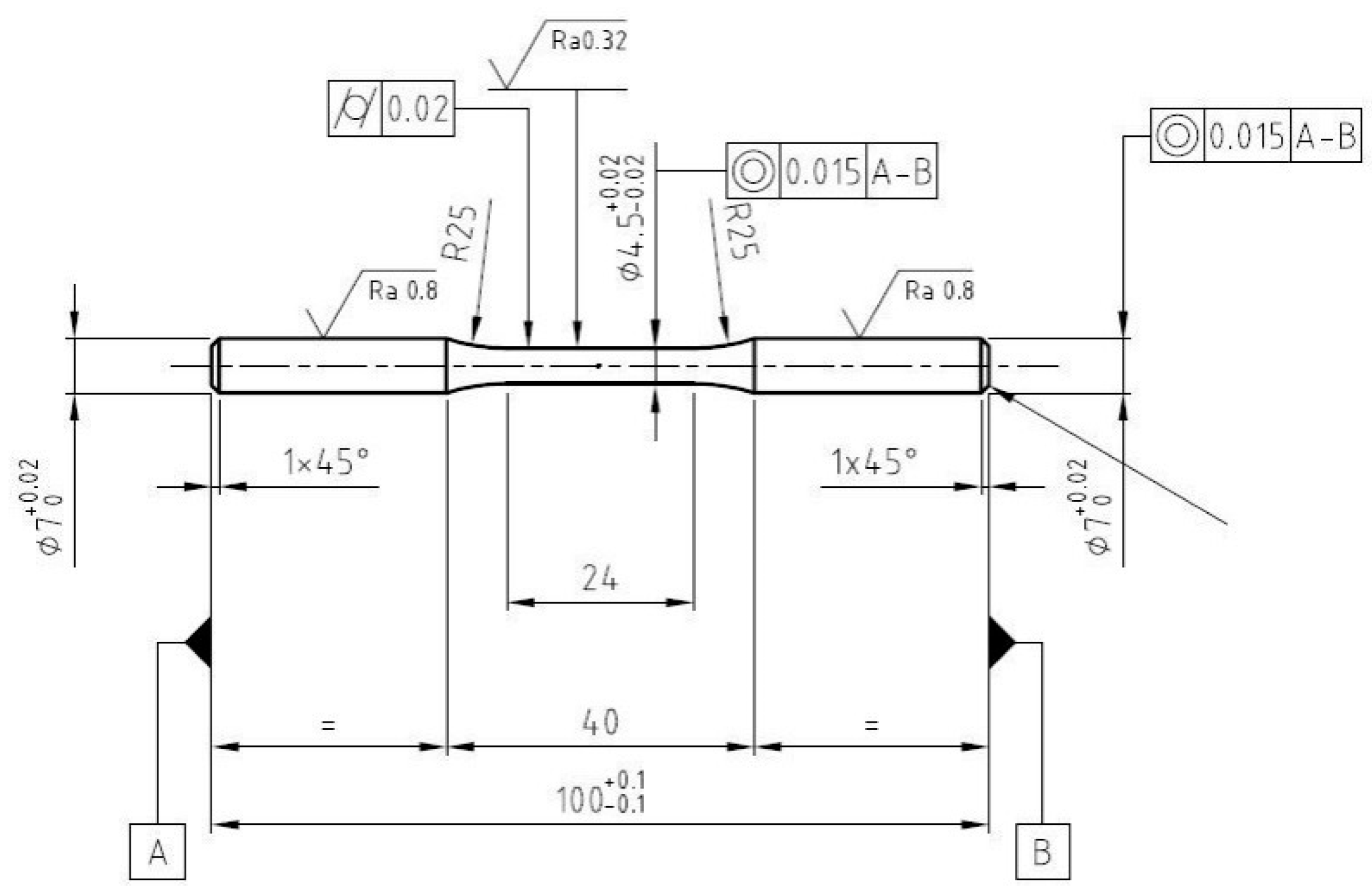
Figure 1. Tensile static and rotating bending fatigue specimen design. Dimensions are shown in mm.
Metals 15 00931 g001
Figure 2. Scheme of ball fatigue testing equipment.
Metals 15 00931 g002
Figure 3. (a,b) Martensitic and (c,d) bainitic microstructure of the examined test specimens (a,c) and bearing balls (b,d). Optical metallography.
Metals 15 00931 g003
Figure 4. Stress–strain curves for tensile specimens.
Metals 15 00931 g004
Figure 5. Tensile fracture surface: (a) bainitic specimen; (b) martensitic specimens with different magnifications.
Metals 15 00931 g005
Figure 6. Rotating bending fatigue results: Whoeler diagram. Empty symbols correspond to run-outs. Numbers indicate the corresponding quantity of runout specimens.
Metals 15 00931 g006
Figure 7. Rotating bending fatigue: (a) fractured surface bainitic specimens; (b) martensitic specimens with different magnifications.
Metals 15 00931 g007
Figure 8. Weibull distribution of life of balls for martensitic and bainitic balls.
Metals 15 00931 g008
Figure 9. RCF fracture surface for (a) martensitic and (b) bainitic balls.
Metals 15 00931 g009
Figure 10. Microstructural analysis of RCF fracture surface for (a) surface and (b) core martensitic ball.
Metals 15 00931 g010
Figure 11. Microstructural analysis of RCF fracture surface for (a) surface and (b) core bainitic ball.
Metals 15 00931 g011
Table 1. Elemental composition of the examined steel (lot C, balance Fe).
CCrSiMnCuNiMoAlPS
1.0121.4230.3010.3090.1750.1060.0230.0250.0100.009
Table 2. Steel lots and heat treatment details used for bearing balls and test specimens with martensitic microstructure.
MaterialItemsLotAustenitizingQuenchingTempering
Mart.BallsA845 °C, 15 minOil, room temperature150 °C, 120 min
Cylindrical Spec.B830 °C, 12 minOil, room temperature150 °C, 30 min
Charpy Spec.D830 °C, 17 minOil, room temperature150 °C, 30 min
Table 3. Steel lots and heat treatment details used for bearing balls and test specimens with bainitic microstructure.
MaterialItemsLotAustenitizingBainitic Transformation
Bain.BallsC860 °C, 65 minSalt bath,
250 °C, 35 min
Cylindrical Spec.C860 °C, 65 minSalt bath,
250 °C, 30 min
Charpy Spec.D860 °C, 65 minSalt bath,
250 °C, 30 min
Table 4. Tensile mechanical properties for tested specimens.
Rp0.2 (MPa)Rm (MPa)E (GPa)A% *
Martensitic 1-2606-1
Martensitic 2199626241983.33
Martensitic 3191825501982.62
average195725931982.32
Std. dev.55.238.60.01.2
Bainitic 1-2331-2.2
Bainitic 2192223441981.91
Bainitic 3193323261982.1
average1927.52333.7198.02.1
Std. dev.7.89.30.00.1
* Residual plastic strain.
Table 5. Charpy results for tested specimens.
KV8 (J)
Martensitic 12
Martensitic 22
Martensitic 32
average2
Bainitic 13
Bainitic 23.8
Bainitic 33.8
average3.5
Table 6. Percent austenite decrement.
Martensitic BallsBainitic Balls
SampleBefore TemperingAfter TemperingBefore TemperingAfter Tempering
111.431.384.915.42
210.67<13.371.42
311.37<14.823.13
48.85<15.276.23
510.65<12.573.76
Average10.59<14.193.99
Decrement (%)≈10.5≈0.2
Table 7. Ball dimensional variation.
Sample Martensitic   Balls   μ m 100   m m Bainitic   Balls   μ m 100   m m
14417
25320
34219
45028
55113
64118
75216
84515
94513
105020
Average4718
Table 8. Life duration and fatigue cycles in bearings and balls for martensitic and bainitic bodies.
Test n°Martensitic BallsBainitic Balls
Life (h)Nb (106)Nn (106)Nc (106)Life (h)Nb (106)Nn (106)Nc (106)
1183.1 7.5838.545.75105.24.3622.153.31
2127.5 5.2826.844.01183.17.5838.545.75
3183.1 7.5838.545.7522.90.954.820.72
4183.1 7.5838.545.75147.76.1131.094.64
5183.1 7.5838.545.7597.34.0320.483.06
6183.1 7.5838.545.7570.62.9214.862.22
790.9 3.7619.142.8651.32.1210.81.61
8183.1 7.5838.545.7561.42.5412.931.93
Average 164.6 6.8234.665.1792.43.8319.462.90
Table 9. Surface hardness HV2 for martensitic and bainitic balls before and after fatigue testing.
Martensitic BallsBainitic Balls
HV2HV Ratio (%) HV2HV Ratio (%)
new ball886/new ball736/
Test 7861−2.82%Test 3 734−0.27%
Test 2862−2.71%Test 5 7420.82%
Test 8852−3.84%Test 2 726−1.36%
Disclaimer/Publisher’s Note: The statements, opinions and data contained in all publications are solely those of the individual author(s) and contributor(s) and not of MDPI and/or the editor(s). MDPI and/or the editor(s) disclaim responsibility for any injury to people or property resulting from any ideas, methods, instructions or products referred to in the content.