Article

The Mechanism Underlying the Influence of Temperature on the Fracture Toughness of Dissimilar Steel Welded Joints in Nuclear Power Plants

1
Suzhou Chien-Shiung Institute of Technology, Intelligent Manufacturing College, Suzhou 215411, China
2
Key Laboratory for Anisotropy and Texture of Materials, Northeastern University, Shenyang 110819, China
*
Author to whom correspondence should be addressed.
Metals 2025, 15(11), 1236; https://doi.org/10.3390/met15111236
Submission received: 9 October 2025 / Revised: 2 November 2025 / Accepted: 7 November 2025 / Published: 10 November 2025
(This article belongs to the Section Additive Manufacturing)

Abstract

In this study, the J-integral method was used to evaluate the fracture toughness (JQ) of the isolation layer at the top of SA508-III-309L/308L-316L dissimilar metal welded joints (DMWJs) of a pressure vessel. Tests were carried out at varying temperatures, from room temperature to 320 °C, to study the mechanism underlying temperature effects on unstable crack propagation. The results show that failure occurs in the middle position of the weld isolation layer of the welded joint at all test temperatures. The JQ of the inner diameter of the joint decreases with increased temperature, with a maximum decrease of 31.8%. The analysis shows that the lath ferrite structure in the isolation layer provides a favorable path for crack propagation. The increase in temperature enlarges the difference in thermal expansion between SA508-III steel and the isolation layer, making it easier for second-phase particles in the isolation layer to induce crack initiation and propagation, thus reducing the JQ of the steel. In addition, at high temperatures, the dislocation density of the isolation layer, the deformation resistance of the material, and the difference in the yield ratio of the joint weld all decrease, which is not conducive to the redistribution of the stress field at the tip of the fatigue crack, leading to further reduction in the JQ.

1. Introduction

Dissimilar metal welded joints are extensively applied in nuclear power plants. For example, submerged arc welding is used to weld a typical dissimilar metal joint between a 316L stainless steel safe end and a quenched and tempered SA508-III steel pressure vessel connecting pipe, meeting structure and component manufacturing requirements under different temperatures and corrosion conditions [1,2]. These joints are key components of the primary circuit in pressurized water reactor nuclear power plants. During operation, they need to withstand harsh working conditions, such as high temperature and high pressure, alternating stress, and strong neutron irradiation for a long period. These joints often fail because of corrosion fatigue, stress corrosion, toughness/brittle damage, or fractures [3,4,5].
Dissimilar steel welded joints mainly comprise a base metal, a heat-affected zone, a fusion zone, and a weld zone. The weld zone includes the isolation layer and the butt weld after surfacing. Much research and experience have shown that dissimilar metal weld seams are the most prone to failure in structures [6], and their service life is much shorter than their design life. Research on the failure mechanisms of these key components in nuclear power plants under service conditions is urgently needed [7,8]. Due to the different thermal expansion coefficients between dissimilar metals, high local stress (strain) is generated near the fusion boundary during welding shrinkage, which makes the weld prone to stress corrosion failure [9,10,11,12,13,14,15]. In addition, residual stress/strain may form near the weld seam [16,17]. Dong et al. [18,19,20,21] comprehensively studied the residual strain distribution on the safe-end joint of a CAP1400 nuclear power plant nozzle using a finite element model. The results show that welding residual stress is mainly affected by the geometric shape and material properties of the nuclear power plant structure. The weld area on the inner surface of the nozzle’s safe end in a CAP1400 nuclear power plant contains significant axial tensile residual stress, significantly increasing its sensitivity to stress corrosion cracking (SCC). However, the effect of welding residual stress on other mechanical properties is not considered in this model. Gu et al. [22] studied the effect of residual stress introduced by local loading on the fracture behavior of dissimilar metal welded joints (DMWJs) under different constraint conditions. They found that tensile and compressive stresses differ depending on the relative position of the local loading region at the crack tip, thus affecting the fracture toughness of the joint. However, the actual stress state in nuclear power plant engineering is poorly understood, and the mechanism underlying the effect of temperature change on the stress state and fracture toughness is not entirely clear. Younise et al. [23,24,25] found that the inhomogeneity and constraint conditions of materials significantly impact their resistance to crack initiation and propagation. Three-dimensional models of specimens have been developed to predict the difference in fracture resistance between the weld and heat-affected zones; the results show that the heat-affected zone has higher fracture resistance than the weld metal. However, the crack initiation resistance of dissimilar steel welded joints has not been fully analyzed in other areas or service environments. Samal [26,27,28,29,30] et al. evaluated the unstable crack growth behavior of various parts of dissimilar steel welded joints in nuclear power plants. Their research shows that the fracture resistance is lowest at the isolation-zone–weld-seam interface, where the hard-facing layer and the heat-affected zone (HAZ) overlap, forming a coarse-grain heat-affected zone. Ductility is also the lowest at the interface, which reduces the bearing capacity of the single-edge notch bending (SEB) specimen; however, the microscopic mechanism underlying this phenomenon in the hard-facing layer has not been thoroughly described. In sum, the performance of dissimilar steel welded joints in nuclear power plants is greatly affected by the material, the binding force, the size, and other factors. SA508-III-309L/308L-316L dissimilar steel welded joints at the safe ends of inlet nozzles in nuclear reactor pressure vessels have a radius and thickness of 367.5 mm and 445 mm, respectively, with a thickness-to-radius ratio of 1:1.21. In the authors’ former study, the authors conducted a tensile property test on the whole joint. The results showed that the joint’s fracture failure occurred in the isolation layer, confirming that it was the weakest position of the joint. However, the micro-mechanism at the weak joint position and the mechanism underlying the ambient temperature’s influence on plastic deformation at the crack tip of the joint are unclear. Therefore, this study uses the J-integral method to analyze the fracture mechanism of the isolation layer zone at the top of an SA508-III-309L/308L-316L dissimilar steel welded joint while raising the temperature from 25 °C to service temperature. The results will help elucidate the mechanism by which temperature affects unstable crack propagation behavior in the joint and clarify the interactive relationship between strain, temperature, and unstable crack propagation, providing a reference for the safe operation of nuclear power plants.

2. Materials and Methods

2.1. Materials

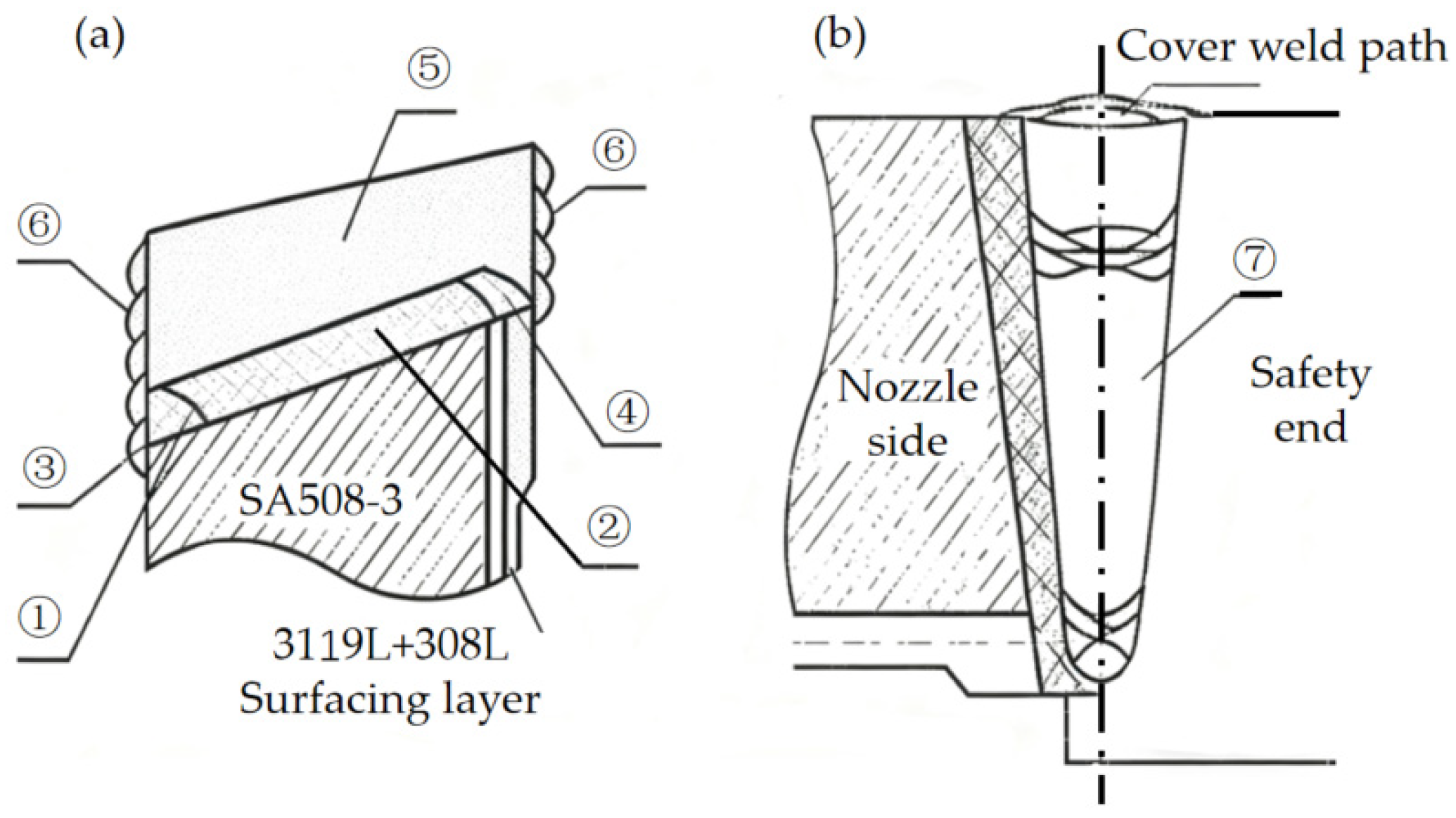
An SA508-III-309L/308L-316L DMWJ produced by China First Heavy Industry (Qiqihaer, China) is the research object of this study. The base metals of the welded joint are 316L stainless steel and SA508-III steel. ER308L and ER309L are filler metals. Figure 1 is a schematic diagram of the DMWJ, and Table 1 details its chemical composition data.

2.2. Welding Process

The welding groove angle of a low-alloy SA508-3 steel nozzle was machined to 10 degrees. Before surfacing the isolating layer, the steel nozzle was preheated to 150~190 °C. After that, hot-wire non-melting electrode gas-shielded welding (hot-wire TIG) was applied, and an ER309L welding wire was used to build up the first layer (transition layer; thickness of about 2 mm) of the isolation layer on the nozzle, with an interlayer temperature ≤ 100 °C. After surfacing the first layer, heat treatment was applied at 250~400 °C for 2 h, and chemical analysis was performed according to RCC-MS3512 requirements [31]. The rest of the isolation layer was welded via hot-wire TIG welding with ER308l. The thickness of the final surfacing isolation layer was about 6 mm. In the manufacturing of large pressure vessels, intermediate stress-relief annealing (ISR) is carried out on the isolation layer to prevent hydrogen-induced cracks in the weld, eliminate harmful gases in the weld area, and reduce the hardness of the welded joint. In this study, heat treatment was carried out at 615 ± 15 °C, which was maintained for 1 h; the rate of temperature change (increase and decrease) during the heat treatment was ≤55 °C/h, and the outlet temperature was ≤300 °C. After the heat treatment, the isolation layer was subjected to 100% non-destructive testing. After it passed the test, it was butt-welded with the safe end of austenitic stainless steel 316L for multiple passes. The isolation layer and the 316L austenitic stainless steel safe-end transition pipe were butt-welded using multi-pass submerged arc mechanical welding (SAW). After butt-welding, stress-relief heat treatment was carried out on the vessel components. Table 2 shows the welding parameters of the welded joints, and Figure 2 shows their welding sequence.

2.3. Mechanical Property Tests

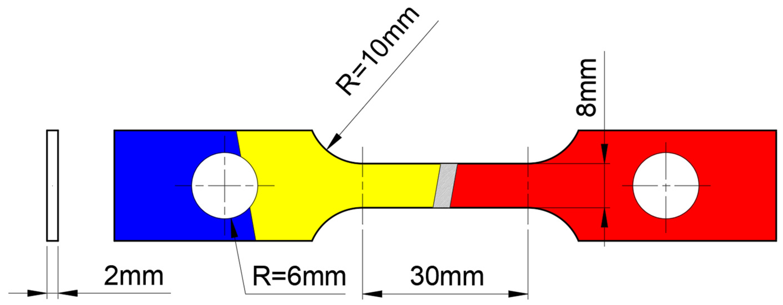
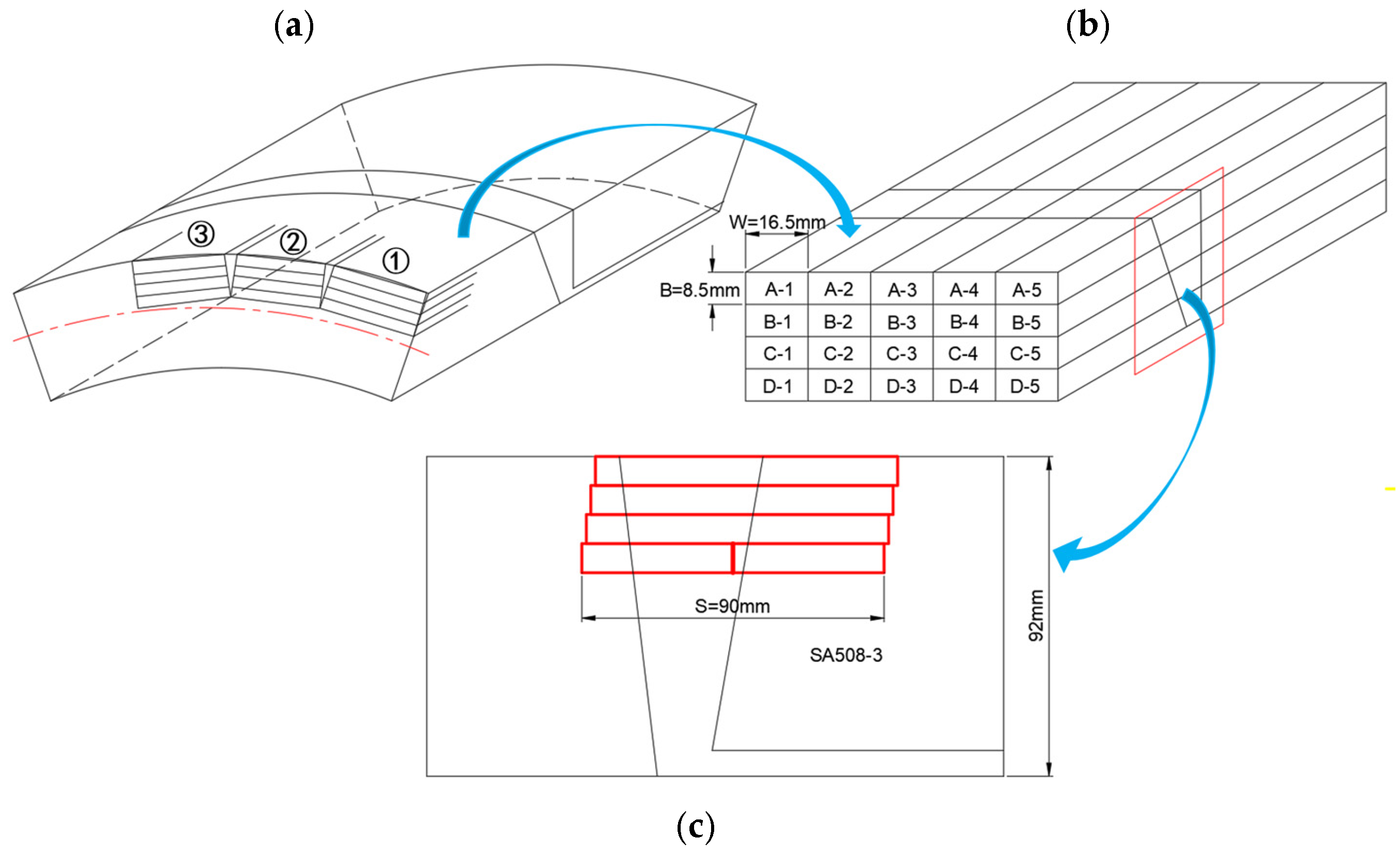
The tensile test of the joint was based on the ASTM E8–21 standard [32]. The sample size was 2 mm × 8 mm × 30 mm, and the entire isolation zone was contained in the working part of the tensile specimen (Figure 3). The axial direction of the sample was consistent with the forging direction. During the test, the strain rate was controlled at 5 × 10⁻⁴/s. The fracture toughness test was based on the ASTM E1820-23b standard [33]. The fracture toughness value of the joint was measured using a three-point bending specimen. If the sample’s thickness and ligament width meet the standards of the plane strain fracture toughness test (B,b0 > 25 JQ/σY), then the conditional fracture toughness is JQ = JIc. Considering that the size of the actual component and the accuracy of the test measurement have difficulty meeting the standard, the variation rule was evaluated using the conditional fracture toughness value, JQ. The sample size parameters were set as follows: width, 16 mm; thickness, 8 mm; and length, 90 mm. The mechanical notch position of the three-point bending sample was taken in the isolation layer area, and the notch direction was perpendicular to the forging direction of the steel (Figure 4). The ratio of the initial crack, a0, to the total width is 0.55 (a0 refers to the initial crack length, which is controlled within a range of 8.8 to 8.9 mm). The sample was loaded to the initial crack length, a0, using a Shimadzu EHF-F1 fatigue testing machine (Shimadzu Corporation, Kyoto, Japan). The fracture toughness and tensile tests were performed using a SANS-CMT5105 testing machine (Shenzhen Sans Testing Machine, Shenzhen, China). The fracture toughness test was carried out using a constant loading rate of 1 mm/min at room temperature (25 °C), 150 °C, 260 °C, and 320 °C. The temperature accuracy in the heating process was ±1 °C. After reaching the preset temperature, the sample was maintained at that temperature for 30 min before loading. To ensure the reliability of the experimental data, three and five samples were used for each tensile test state and fracture toughness state, respectively, and the results were averaged.

2.4. Structure Observation

The original structure of the DMWJ was observed using an Olympus GX71 microscope (OM, Olympus Corporation, Tokyo, Japan), and its fracture surface was analyzed using a JEOL 6510A electron microscope (SEM, Japan Electron Optics Laboratory, Tokyo, Japan). Transmission electron microscope samples were prepared using the electrolytic double-jet process. The specific parameters were as follows: 9% perchloric acid and 91% ethanol electrolyte were used, the working temperature was maintained at −35 °C, the operating current was 35 mA, and the voltage was 25 V. The microstructure of the samples was characterized by a TECNAI G2 transmission electron microscope (TEM, Thermo Fisher Scientific Inc., Waltham, MA, USA), including morphological observation, composition, and structure analyses of the precipitates.

3. Results and Discussion

3.1. Optical Structure Characteristics of Different Regions of DMWJ

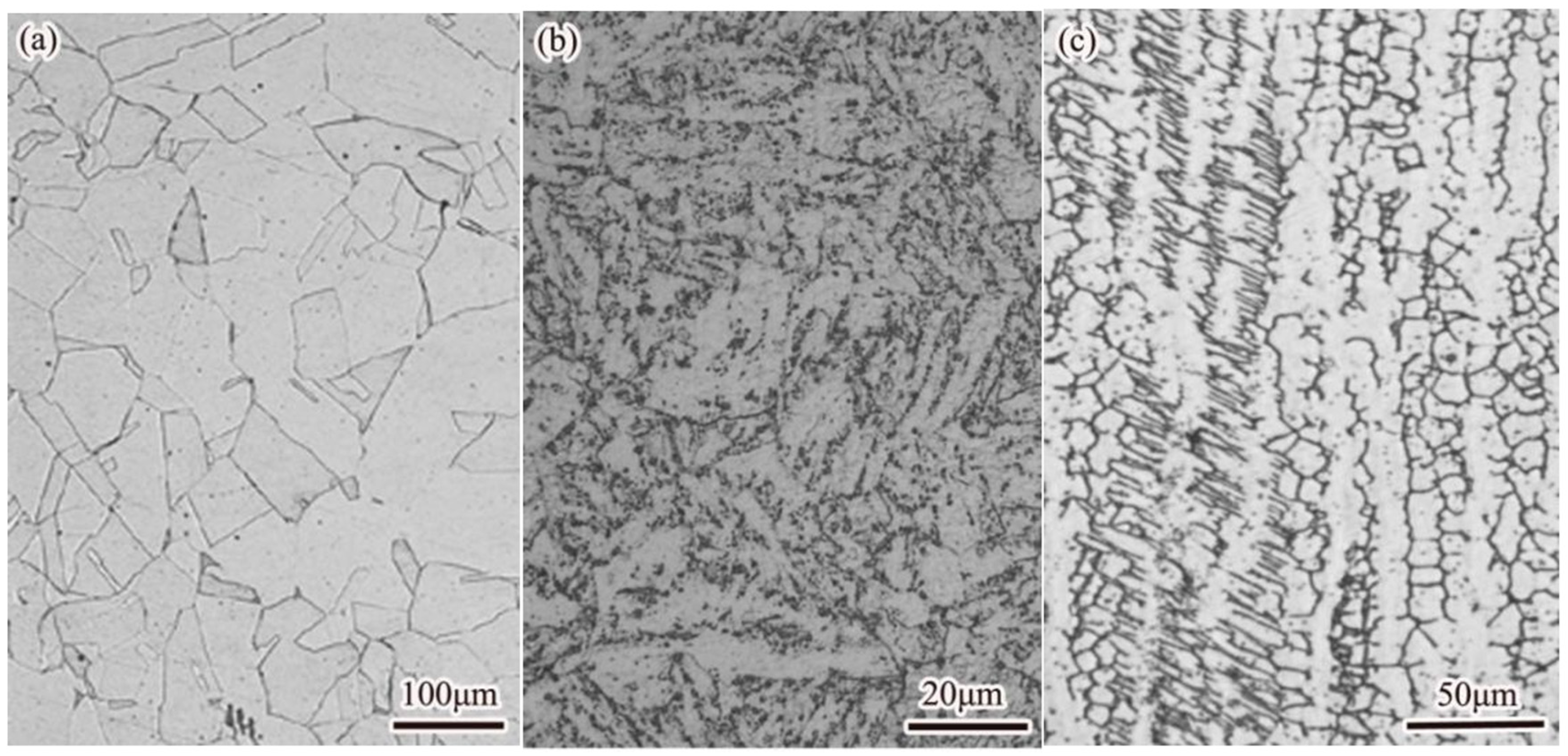
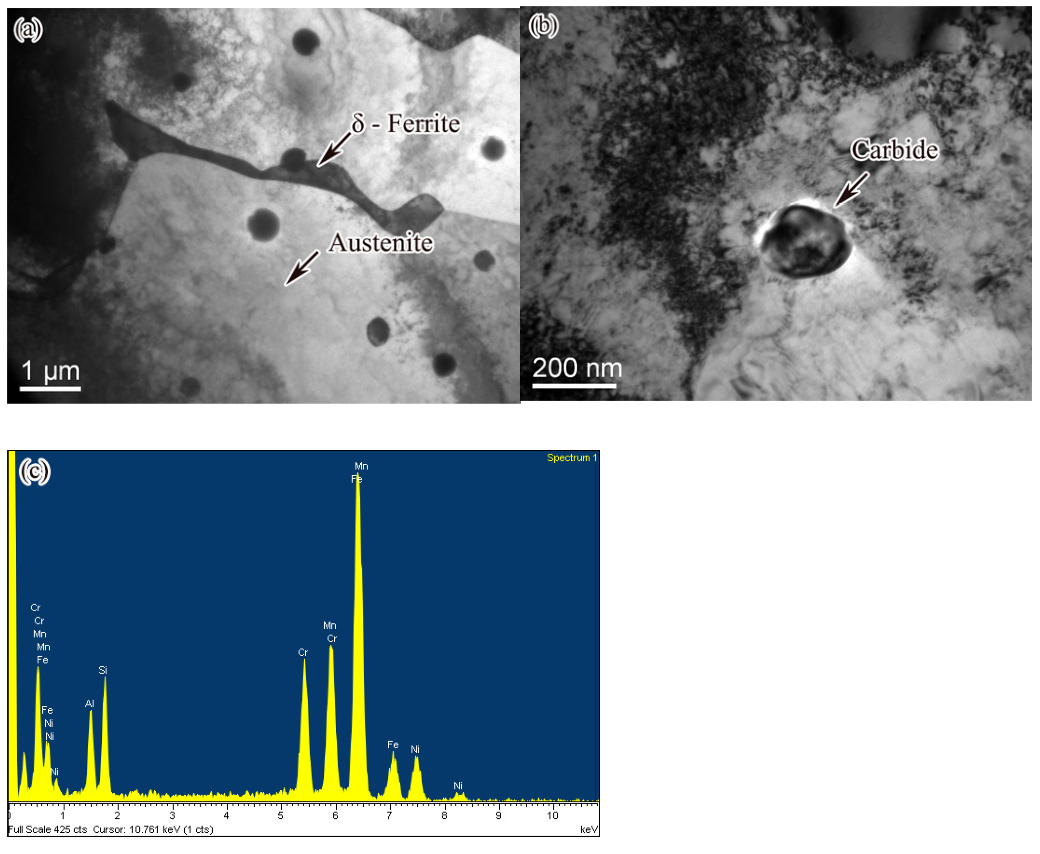
Figure 5 shows the optical organization of each region of the DMWJ. Figure 6 shows the TEM morphology of the DMWJ and the EDS energy spectrum analysis of the carbides. The microstructure of the 316L steel mainly comprises coarse equiaxed austenite grains with some annealing twins (Figure 5a), and the average grain size is 50 μm. The base-metal SA508-III steel comprises a tempered sorbite structure after high-temperature quenching and tempering treatment (Figure 5b), with an average grain size of 20 μm. The weld is mainly composed of paragenetic cellular austenite and columnar austenite (Figure 5c), with an average grain size of 10 μm. Furthermore, δ-ferrite precipitates are observed at and within the grain boundary (Figure 6a), with 8.6% content, accompanied by randomly distributed carbides. According to TEM morphology and energy spectrum analysis, the carbides are the M23C6 type (Figure 6b,c). As shown in Table 3, in terms of energy spectrum composition, δ-ferrite has higher Cr content and lower Ni content than austenite. Therefore, ferrite is able to transfer Cr to austenite, making it difficult for austenite grains to form a Cr-poor layer. This reduces the possibility of precipitation of intergranular carbides and improves the weld’s ability to resist crystal corrosion [34].

3.2. Mechanical Properties of DMWJ at Different Temperatures

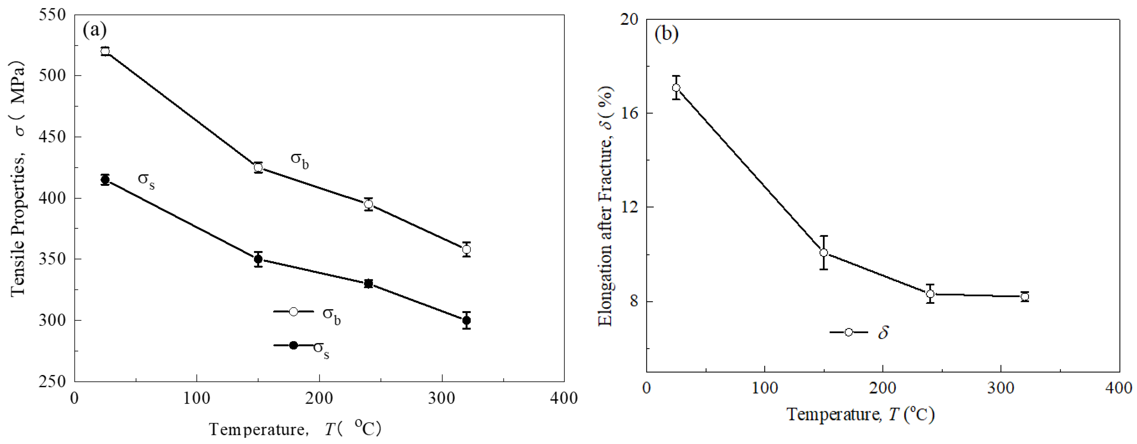
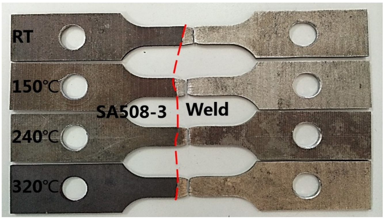
Figure 7 shows the changes in tensile property parameters of the DMWJ at different temperatures. With increased temperature, the mechanical parameters of the DMWJ decreased significantly. As the temperature rose from room temperature to service temperature (320 °C), the yield strength and tensile strength showed an approximate linear downward trend, with decreases of 26.9% and 31.9%, respectively, with partial strength loss due to thermal softening. The plasticity first decreased rapidly and then leveled off, from 17.10% at room temperature to 8.19% at 320 °C, with a decrease of 52.1%. Figure 8 shows the fracture specimens at different temperatures, where the red line represents the position of the fusion line. The fracture location of the joint is concentrated in the middle position of the weld isolation layer, which indicates that this area is a weak link in the service condition of the joint.

3.3. Fracture Toughness of DMWJ Weld Isolation Layer

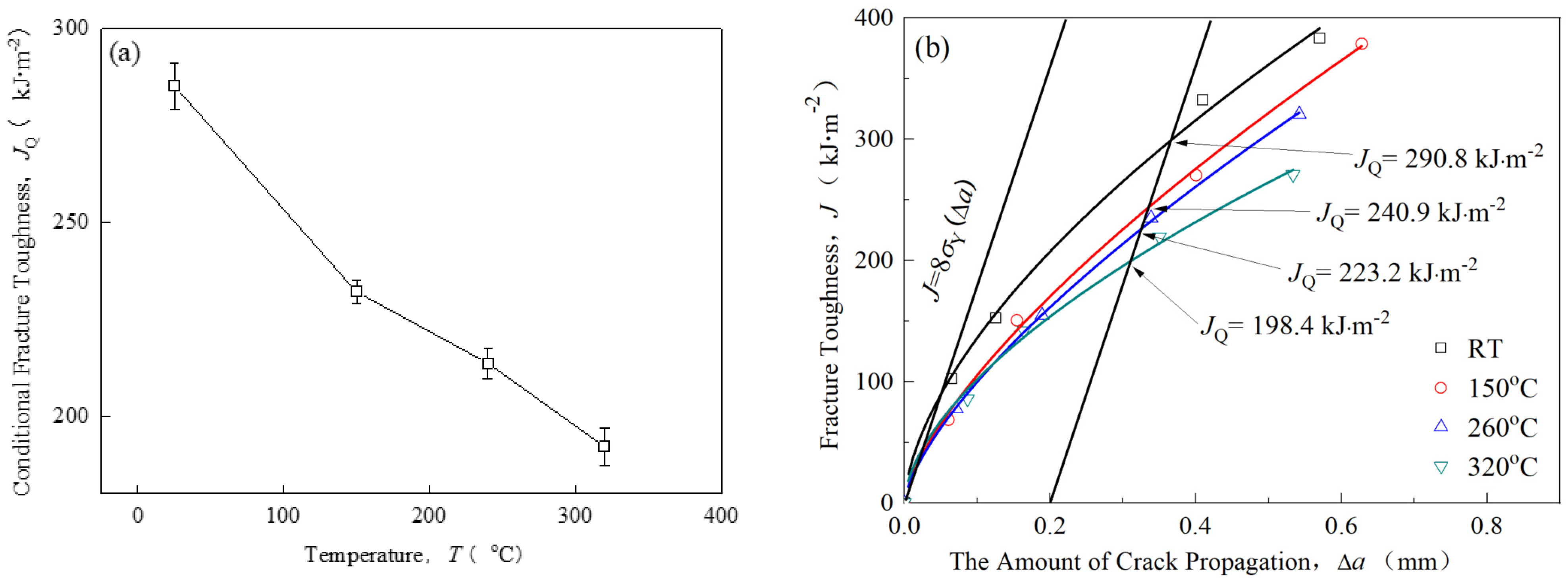
Figure 9 shows the curve of the DMWJ’s fracture toughness with temperature. With the increase in temperature, the fracture toughness decreases linearly (Figure 9a). The linear regression equation between fracture toughness (JQ) and temperature (T) is shown in Formula (1), in which the regression coefficient (slope) is −0.31, indicating that the average decrease in fracture toughness, JQ, is 0.31 kJ/m2 for every 1 °C increase in temperature. At room temperature, the JQ value is 290.8 kJ/m 2; when the temperature rises to 320 °C, the JQ value is 198.4 kJ/m 2, with a decrease of 31.8% (Figure 9b).
JQ = −0.31T + 288(R2 = 0.96, absolute error: ±5 kJ/m2)
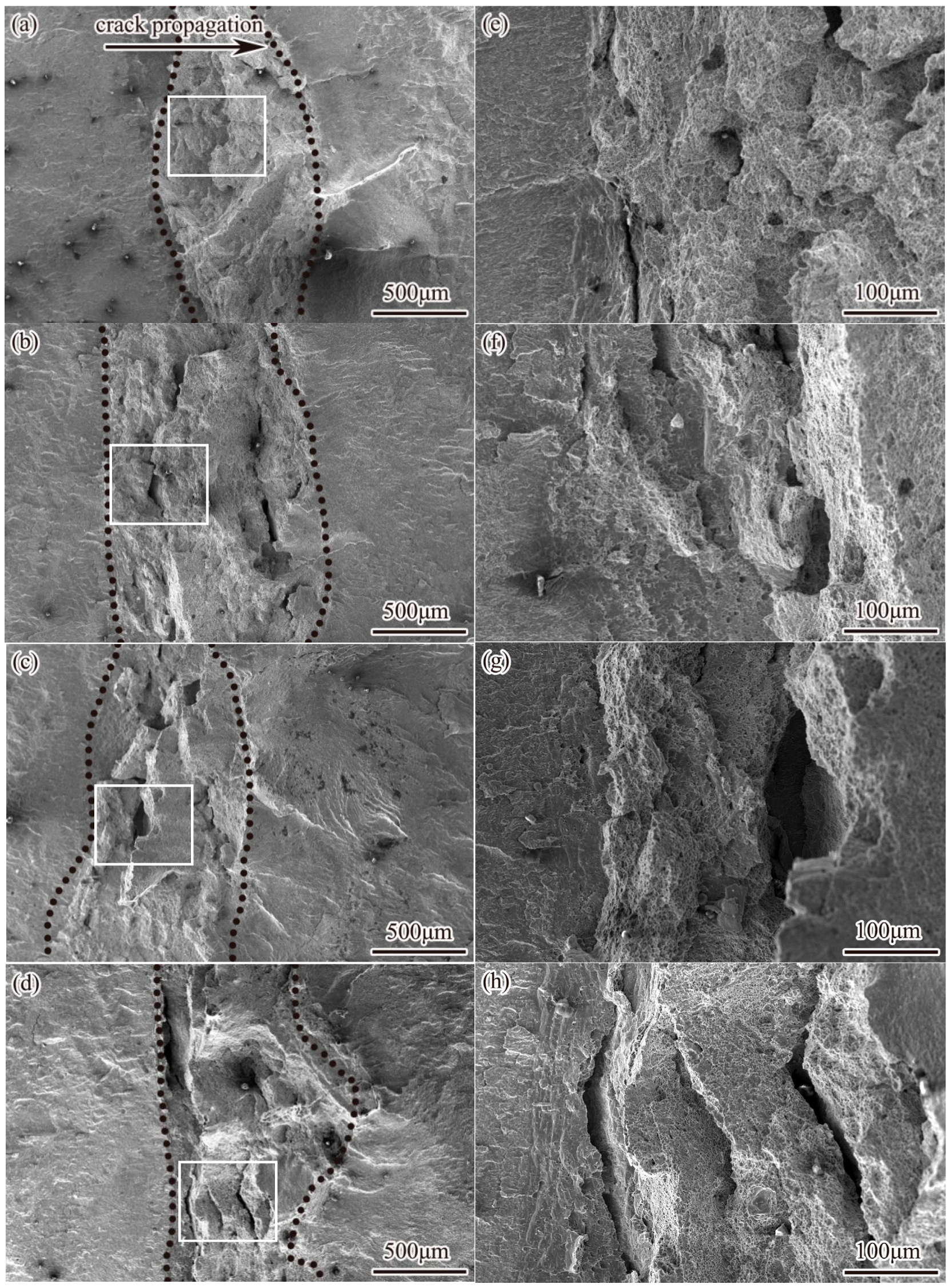
Figure 10 depicts the failure fracture surface of the DMWJ at different temperatures; the right figure shows the enlarged morphology of the corresponding white box area in the left figure. The main crack extends from left to right. The area between the black dotted lines is the crack propagation area, and the area marked by the white frame line in the black dotted line is where the unstable crack initiated. The macro-fracture is relatively flat at room temperature, with few secondary cracks (Figure 10a). With increased temperature, the fracture surface gradually becomes more uneven, and the number of large-scale secondary cracks along the thickness direction of the specimen increases (Figure 10b–d).
At room temperature, the crack initiation process is relatively gentle, the step feature is not obvious, and the secondary crack size is relatively small (Figure 10f). However, at a high temperature of 320 °C, the step at the crack initiation point increases significantly, and the secondary crack becomes larger. This phenomenon indicates that the high-temperature environment intensifies the stress concentration effect at the crack front, decreasing the material’s plasticity and thus promoting the initiation and propagation of cracks (Figure 10h).
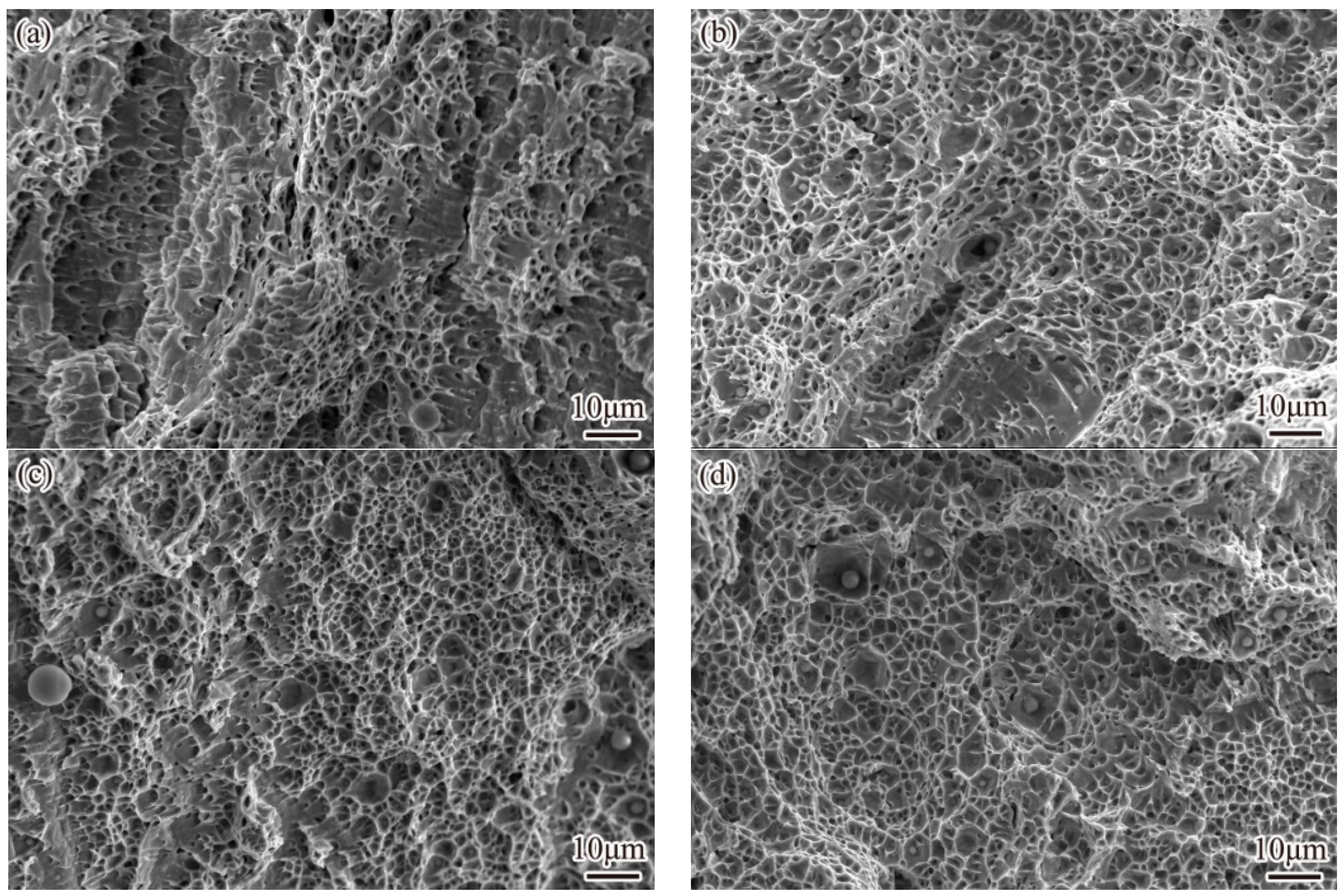
Figure 11 shows a micrograph of the DMWJ’s failure fracture. At all temperatures, the micro-fractures showed dimple shapes, and numerous positive and parabolic dimples were distributed on the fracture surface, resulting in a mixed morphology. This confirmed that the fracture process was a tensile–shear mixed mode. With an increase in temperature, the dimple size decreases significantly, and the plasticity decreases accordingly.

3.4. Influence of Ferrite Morphology on Joint Fracture Behavior

Figure 12 shows the morphology of ferrite at different positions of the joint. The distribution pattern of ferrite in austenitic welds is related to the cooling conditions. The weld metal near the fusion zone has a fast cooling rate and a large temperature gradient. The δ-ferrite grows rapidly in the form of cellular crystals and crystallizes as primary austenite. Cr element is easily enriched between grains and undergoes eutectic transformation [35,36], forming point-like or short rod-shaped ferrite distributed along the austenite grains. The temperature gradient of the weld isolation layer with a slightly slower cooling rate shrinks to form Flat noodles ferrite (Figure 12b). Flat noodles ferrite is conducive to crack initiation and propagation, so this is the weak zone of the weld. The cooling rate in the middle of the weld seam slows down, resulting in the precipitation of primary ferrite, which grows into dendritic crystals with a skeletal or dendritic morphology. At the same time, there is also a small amount of worm-like ferrite (Figure 12c,d). The skeletal ferrite disrupts the directionality of the austenite columnar crystals, and the austenite and ferrite interlock with each other. This distribution pattern increases the number of grain boundaries and phase interfaces in the butt weld metal, which can effectively hinder the movement of dislocations. Therefore, cracks are not easily formed here, and once again explains the reason why the final fracture occurs in the weld isolation layer.

3.5. Mechanism Underlying Temperature’s Effect on DMWJ Crack Propagation

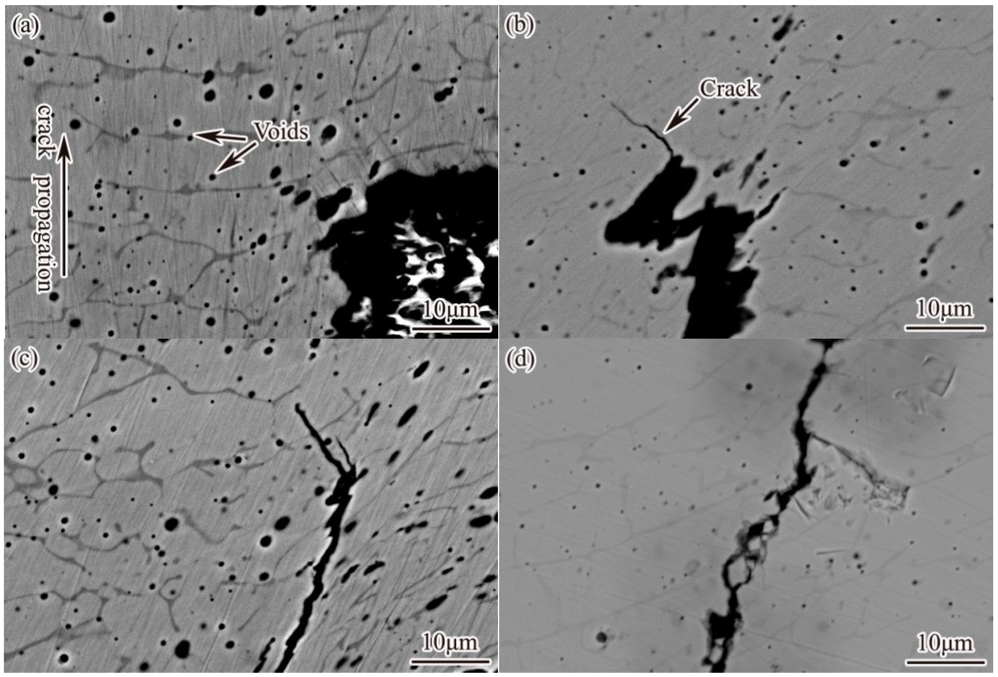
Figure 13 shows the morphological characteristics of the side backscatter of the DMWJ’s failure fracture surface at various temperatures. The main crack follows a bottom-up propagation path. The gray porphyritic area is the ferrite structure. Many holes are distributed near the fracture section. Transgranular growth cracks are evident on the fracture surface of the specimen at all test temperatures except room temperature.
Figure 13d shows the microscopic morphological characteristics of the fracture interface at 320 °C; in this image, the typical crack propagation path along the second-phase particles can be observed. This indicates that at high temperatures, carbide becomes the main crack nucleation location in the weld area. After plastic deformation, dislocation movement around the carbide is blocked, and with the increase in stress, dislocations accumulate and form micropores. Under a sustained load, these micropores aggregate and connect through dislocation movement; they then form macro-cracks and carry out unstable propagation and finally fracture. Since the base and weld metals have different linear expansion coefficients, an increase in temperature gradually increases the difference in the two metals’ thermal expansion. The distribution of mechanical properties is thus significantly uneven, intensifying the incompatible deformation and enhancement of the driving force of crack propagation in the DMWJ at a high temperature [37]. High temperatures weaken the strength and plasticity of the DMWJ (Figure 9), and the energy required for connecting holes is reduced. Cracks form more easily under three-dimensional stress, thus accelerating the unstable crack propagation and reducing the fracture toughness.
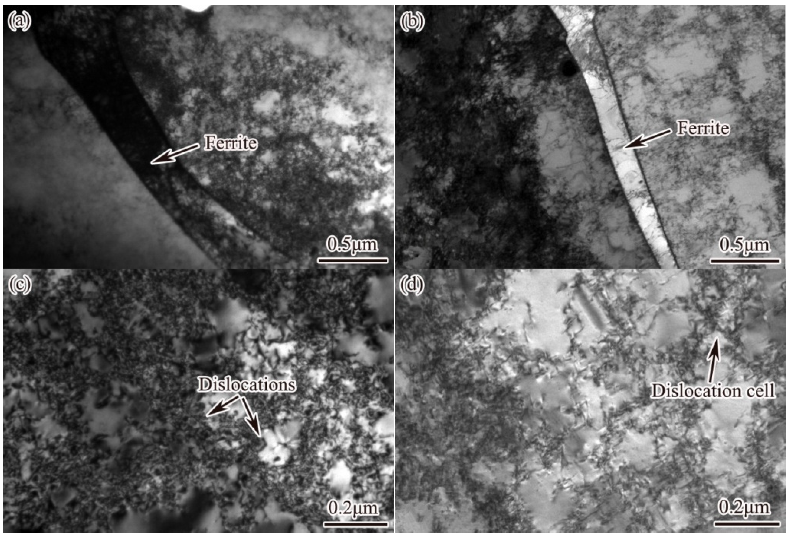
Figure 14 shows the dislocation distribution in the DMWJ after tensile deformation at different temperatures. Many dislocations can be found in the ferrite and austenite grains after deformation at room temperature (Figure 14a,c). However, at 320 °C (Figure 14b,d), dislocations are mainly concentrated in the austenite phase, and the number of dislocations in the ferrite phase is significantly reduced. The dislocation density at 320 °C is significantly reduced, and a typical large-scale cellular structure forms. The formation of this structure requires the material to have high stacking fault energy and a cross-slip phenomenon, which is a typical feature of polycrystalline materials in the multi-slip process. The high-temperature environment decreases the dislocation density in welded joints and forms a large dislocation cell structure. This is because the high temperature provides thermal activation energy to the hindered dislocations and activates new slip systems, such as cross-slip screw dislocations, climbing edge dislocations, and cut step movement dislocations through vacancies and atomic diffusion. These mechanisms jointly promote the release of dislocations, thus reducing the dislocation density, leading to material softening and strength reduction [38]. In addition, the stacking fault energy of the face-centered cubic metal is temperature-sensitive. With the increase in temperature, the increased stacking fault energy will further promote cross-slip dislocation, and large-scale cellular structures are more easily formed [39].
The increase in temperature will lead to the release of dislocations, which reduces the dislocation density, softening the welded joints and reducing their resistance to crack propagation. At the same time, with the increase in temperature, the size of the dislocation cellular structure increases, weakening the coordinated deformation ability of the welded joint and reducing its plasticity, thus accelerating unstable crack propagation and reducing the fracture toughness of the DMWJ.

3.6. Effect of Yield Strength Difference on DMWJ Crack’s Unstable Propagation

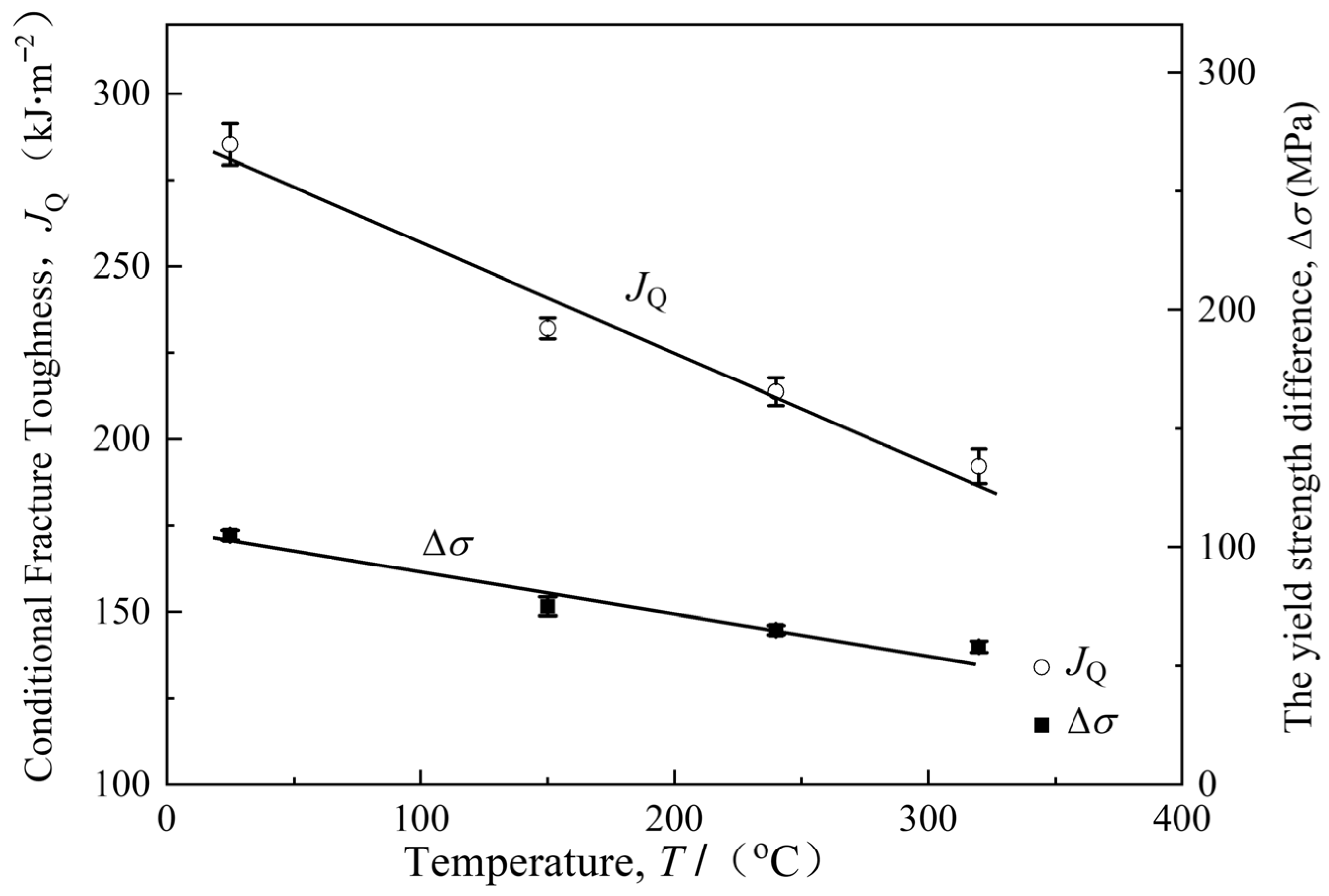
The yield strength difference is the difference between the yield strength and tensile strength of materials, reflecting the deformation-strengthening effect caused by dislocation movement in plastic deformation. As the yield strength difference increases, more stress is required before the material breaks after yielding, indicating that the material has a significant work-hardening (or strain-hardening) ability. Research shows that there is a certain correlation between yield strength difference and fracture toughness [40].
According to the strength data for the DMWJ at the various temperatures measured in Figure 1, the yield difference, Δσ, corresponding to each temperature point can be calculated, as shown in Formula (2):
Δ σ = σ 0 . 2 σ b
Figure 15 shows the change curve of the DMWJ’s JQ and Δσ with the increase in temperature. JQ and Δσ are linearly related to T, as shown in Formulas (1) and (3):
Δ σ = 105 0.16 T   ( R 2 = 0.94 ,   absolute error : ± 6   kJ / m 2 )
where T is the test temperature; Δσ is the joint yield strength difference; and JQ is the conditional fracture toughness.
Formula (3) is substituted into Formula (1) to obtain
J Q = 1.93 Δ σ + 84.6   ( R 2 = 0.95 ,   absolute error : ± 4.6   kJ / m 2 )
Formula (4) shows that there is a proportional linear relationship between the JQ and Δσ values of the welded joint. With the increase in temperature, the welded joint’s Δσ decreases, leading to a corresponding decrease in JQ. The relationship between fracture toughness and the yield strength difference is greatly affected by the material, the environment, the stress distribution, and other factors. For different materials and environments, it is necessary to re-analyze their regularity.
At a high temperature, the dislocation density in the DMWJ decreases after plastic deformation (Figure 12). At room temperature, a higher dislocation density enhances the deformation-strengthening ability of the material and increases the yield strength difference. This large yield strength difference helps to alleviate the stress concentration at the fatigue crack tip, and crack tip propagation is hindered; thus, the fracture toughness is high.
After bending at 320 °C, the dislocation density of the DMWJ decreases, indicating that its deformation resistance has weakened, reducing the tensile strength; subsequently, the yield strength difference is reduced. This small yield strength difference increases the stress concentration at the crack tip, promoting the formation of secondary cracks nearby (Figure 10), accelerating crack growth, and reducing the fracture toughness.

4. Conclusions

  • During the tensile process, from room temperature to 320 °C, the strength and plasticity of the DMWJ decreased significantly, and the isolation layer was the weakest area of the welded joint. The decrease in partial strength is closely related to the softening of the material, while the decrease in plasticity is due to the increased tensile residual stress caused by the increased thermal expansion, accelerating the failure of the material.
  • The fracture toughness of welded joints decreases with increased temperature for the following reasons: First, the high temperature releases stacking dislocations, reduces the dislocation density, and then weakens the tensile strength and reduces the yield ratio. This change is not conducive to the redistribution of the stress field at the fatigue crack tip; secondary cracks are more easily initiated near the crack tip, accelerating crack propagation and reducing the fracture toughness of the joint. Secondly, with the increase in temperature, the thermal expansion difference between the base metal and the weld metal increases, and the dislocation cell size increases, reducing the joint’s plasticity, accelerating the crack growth rate, and further reducing the fracture toughness.

Author Contributions

Conceptualization, J.L. (Jiahua Liu) and A.Z.; methodology, J.L. (Jiahua Liu), L.W., F.J., H.X., L.G. and J.L. (Jiong Luo); software, J.L. (Jiahua Liu), A.Z. and J.L. (Jiong Luo); validation, J.L. (Jiahua Liu), A.Z. and J.L. (Jiong Luo); formal analysis, F.J. and L.G.; investigation, J.L. (Jiahua Liu), A.Z. and L.W.; resources, A.Z. and L.W.; data curation, J.L. (Jiahua Liu), A.Z., H.X. and J.L. (Jiong Luo); writing—original draft preparation, J.L. (Jiahua Liu); writing—review and editing, J.L. (Jiahua Liu), A.Z., L.W., F.J., H.X., L.G. and J.L. (Jiong Luo); visualization, J.L. (Jiahua Liu) and L.G.; supervision, A.Z.; project administration, J.L. (Jiahua Liu); funding acquisition, J.L. (Jiahua Liu), A.Z. and F.J. All authors have read and agreed to the published version of the manuscript.

Funding

The Natural Science Foundation Project for Universities in Jiangsu Province (25KJD460008); Jiangsu University’s “Blue Project” Funding (81220001); the 2024 Taicang City Basic Research Program Mandatory Project (TC2024JC27); and the Innovative Team For Multi-Scale Material Forming and Testing Technology of Aviation Components (2023JXKYTD02).

Data Availability Statement

The original contributions presented in this study are included in the article. Further inquiries can be directed to the corresponding author.

Conflicts of Interest

The authors declare no conflicts of interest.

References

  1. Sonar, T.; Ivanov, M.; Trofimov, E.; Liu, K.; Shcherbakov, I.; Shaburova, N.; Samoilovskikh, P. A critical review on dissimilar welding of ferritic-martensitic steel and austenitic stainless steel using gas tungsten arc welding process: Weldability issues, processing, and performance characteristics of joints. J. Manuf. Process. 2025, 133, 811–864. [Google Scholar] [CrossRef]
  2. Gao, Z.; Zhao, L.; Han, Y. Investigation on Residual Stress in SA508/Inconel Metal/CF8A Dissimilar Welded Joint for Nuclear Steam Generator Safe End Using Different Processes. Nucl. Technol. 2023, 210, 471–485. [Google Scholar] [CrossRef]
  3. Zhao, L.; Sun, Y.; Shi, Z.; Yang, B. Analysis of Crack Propagation Behaviors in RPV Dissimilar Metal Welded Joints Affected by Residual Stress. Materials 2023, 16, 6578. [Google Scholar] [CrossRef] [PubMed]
  4. Das, M.; Kumar, S.; Singh, P.K.; Ghosh, M. Correlating Microstructure with Mechanical Properties for Different Regions of Dissimilar Metal-Welded Joints. J. Mater. Eng. Perform. 2025, 5, 1–14. [Google Scholar] [CrossRef]
  5. Park, J.; An, G.; Park, J. The Effect of Hydrogen Embrittlement on Fracture Toughness of Cryogenic Steels. Metals 2025, 15, 1139. [Google Scholar] [CrossRef]
  6. Jan, H.; Hana, S.; Sarka, M.; Ambroz, O.; Mrna, L. Cycllc Low-thermal Aging of Dissimilar Austenitic Steel Welds Used in Nuclear Power Plants. MM Sci. J. 2024, 12, 7865–7871. [Google Scholar] [CrossRef]
  7. Liu, Z.F.; Wu, W.H.; Ping, P.; Chen, Z.H. Research on Welding Technology of Safety End of Reactor Pressure Vessel Nozzle for Marine Nuclear Power Platform. Met. Process. 2020, 4, 38–40. [Google Scholar]
  8. Sun, Y.; Xue, H.; Yang, F.Q. Mechanical Properties Evaluation and Crack Propagation Behavior in Dissimilar Metal Welded Joints of 304 L Austenitic Stainless Steel and SA508 Low-Alloy Steel. Sci. Technol. Nucl. Install. 2022, 2022, 3038397. [Google Scholar] [CrossRef]
  9. Zhao, L.Y.; Yang, B.; Wang, Z. Prediction of Crack Propagation Directions in Dissimilar Metal Welded Joints Using Phase-Field Models and Discussion of Its Mechanisms. Sci. Technol. Nucl. Install. 2024, 2024, 5543346. [Google Scholar] [CrossRef]
  10. Krishnan, S.A.; Nikhil, R.; Parnaik, A.; Moitra, A.; Vasudevan, M. Investigation on fracture resistance behaviour of dissimilar metal weld joint of modified 9Cr–1Mo steel and AISI 316LN SS. Int. J. Press. Vessel. Pip. 2024, 211, 105260. [Google Scholar] [CrossRef]
  11. Wang, H.T.; Wang, G.Z.; Xuan, F.Z.; Tu, S.T. Numerical investigation of ductile crack growth behavior in a dissimilar metal welded DMWJ. Nucl. Eng. Des. 2011, 241, 3234–3243. [Google Scholar] [CrossRef]
  12. Liu, F.; Hwang, Y.H.; Nam, S.W. Precipitation of sigma-phase and creep-fatigue behavior of 308L steel weldment. Mater. Sci. Eng. A-Struct. Mater. Prop. Microstruct. Process. 2008, 483, 418–421. [Google Scholar] [CrossRef]
  13. Hou, J.; Peng, Q.J.; Takeda, Y.; Kuniya, J.; Shoji, T.; Wang, J.Q.; Han, E.-H.; Ke, W. Microstructure and mechanical property of the fusion boundary region in an Alloy 182-low alloy steel dissimilar weld joint. J. Mater. Sci. 2010, 45, 5332–5338. [Google Scholar] [CrossRef]
  14. Xue, H.; Ogawa, K.; Shohi, T. Effect of welded mechanical heterogeneity on local stress and strain ahead of stationary and growing crack tips. Nucl. Eng. Des. 2009, 239, 628–640. [Google Scholar] [CrossRef]
  15. Ming, H.L.; Zhang, Z.M.; Wang, J.Q.; Han, E.H.; Ke, W. Microstructural characterization of an SA508-309L/308L-316L domestic dissimilar metal welded safe-end joint. Mater. Charact. 2014, 97, 101–115. [Google Scholar] [CrossRef]
  16. Kerr, M.; Prime, M.B.; Swanson, H.; Buechler, M.A.; Steinzig, M.; Clausen, B.; Sisneros, T. Residual Stress Characterization in a Dissimilar Metal Weld Nuclear Reactor Piping System Mock Up. J. Press. Vessel Technol. Trans. Ame 2013, 135, 57–89. [Google Scholar] [CrossRef]
  17. Lee, K.S.; Kim, W.; Lee, J.G.; Park, C.Y.; Yang, J.S.; Kim, T.R.; Park, J.H. Finite element analysis and measurement for residual stress of dissimilar metal weld in pressurizer safety nozzle mock up. J. Mech. Sci. Technol. 2009, 23, 2948–2955. [Google Scholar] [CrossRef]
  18. Dong, W.C.; Gao, D.B.; Lu, S.P. Numerical Investigation on Residual Stresses of the Safe-End/Nozzle Dissimilar Metal Welded Joint in CAP1400 Nuclear Power Plants. Acta Metall. Sin. 2019, 32, 618–628. [Google Scholar] [CrossRef]
  19. Huang, C.C.; Liu, R.F. Structural integrity analyses for preemptive weld overlay on the dissimilar metal weld of a pressurizer nozzle. Int. J. Press. Vessel. Pip. 2012, 90, 77–83. [Google Scholar] [CrossRef]
  20. Park, J.S.; Kim, J.M.; Sohn, G.H.; Kim, Y.H. An Analysis of Residual Stress Improvement for a Dissimilar Metal Nozzle-to-Pipe Weld by Using the Heat Sink Method. Proc. Asme Press. Vessel. Pip. Conf. 2009, 18, 585–589. [Google Scholar]
  21. Joseph, A.; Rai, S.K.; Jayakumar, T.; Murugan, N. Evaluation of residual stresses in dissimilar weld DMWJs. Int. J. Press. Vessel. Pip. 2005, 82, 700–705. [Google Scholar] [CrossRef]
  22. Gu, S.F.; Jin, W.; Wang, X.X. Effect of residual stress introduced by local loading on fracture behaviour of DMWJ under different constraints. Int. J. Press. Vessel. Pip. 2023, 202, 104885. [Google Scholar] [CrossRef]
  23. Younise, B.; Rakin, M.; Gljak, N.; Medjo, B.; Sedmak, A. Effect of material heterogeneity and constraint conditions on ductile fracture resistance of welded joint zones—Micromechanical assessment. Eng. Fail. Anal. 2017, 82, 435–445. [Google Scholar] [CrossRef]
  24. Wang, H.T.; Wang, G.Z.; Xuan, F.Z.; Liu, C.J.; Tu, S.T. Local mechanical properties of a dissimilar metal welded DMWJ in nuclear power systems. Mater. Sci. Eng. A 2013, 5, 108–117. [Google Scholar] [CrossRef]
  25. Li, Y.Y.; Wang, F.; Huang, Y.; Lin, X.; Lin, D.K.; Li, H.; Yang, W.B.; Ding, M.C.; Zhang, Z.W. Effect of residual stress on the fracture behavior of P91 steel. Press. Vessel. 2024, 41, 28–36. [Google Scholar]
  26. Samal, M.K.; Seidenfuss, M.; Roos, E. Investigation of failure behavior of ferritic-austenitic type of dissimilar steel welded joints. Eng. Fail. Anal. 2011, 18, 999–1008. [Google Scholar] [CrossRef]
  27. Yang, C.J.; Gong, X.H.; Gao, Z.P. Research status of fracture failure behavior of metal clad plates. World Nonferrous Met. 2024, 3, 208–210. [Google Scholar]
  28. Seifert, H.P.; Ritter, S.; Shoji, T.; Peng, Q.J.; Takeda, Y.; Lu, Z.P. Environmentally-assisted cracking behaviour in the transition region of an Alloy182/SA 508 Cl.2 dissimilar metal weld DMWJ in simulated boiling water reactor normal water chemistry environment. J. Nucl. Mater. 2008, 378, 197–210. [Google Scholar] [CrossRef]
  29. Gao, F.G. Analysis of Mechanical Field at Cracking Tip in Welded Joint Based on XFEM. Ph.D. Thesis, Xi’an University of Science and Technology, Xi’an, China, 2017. [Google Scholar]
  30. Wang, S.; He, X.; Gui, Y.W.; Wang, Z.; Zhao, K.; Ni, C. Investigation of the Inhomogeneous Mechanical and Crack Driving Force of Low Alloy Steel SA508 and Its Welded 309L/308L Stainless Steel Cladding. Nucl. Sci. Eng. 2022, 197, 623–632. [Google Scholar] [CrossRef]
  31. RCC-M S3512; Material Specifications for Nuclear Island Mechanical Equipment in Pressurized Water Reactors. AFCEN: Paris, France, 2024.
  32. ASTM E8/E8M–21; Standard Test Methods for Tension Testing of Metallic Materials. ASTM International: West Conshohocken, PA, USA, 2021.
  33. ASTM E1820-23b; Standard Test Method for Measurement of Fracture Toughness. ASTM International: West Conshohocken, PA, USA, 2023.
  34. Xiao, J.; Wang, D.; Yang, S.G. Solidification Microstructure and Secondary-Phase Precipitation Behavior of 310S Austenitic Stainless Steel. Metals 2025, 15, 1091. [Google Scholar] [CrossRef]
  35. Kim, J.W.; Lee, K.; Kim, J.S.; Byun, T.S. Local mechanical properties of Alloy 82/182 dissimilar weld DMWJ between SA508 Gr.1a and F316 SS at RT and 320 degrees C. J. Nucl. Mater. 2009, 384, 212–221. [Google Scholar] [CrossRef]
  36. Huang, B.X.; Wang, X.D.; Rong, Y.H.; Wang, L.; Jin, L. Mechanical behavior and martensitic transformation of an Fe-Mn-Si-Al-Nb alloy. Mater. Sci. Eng. A-Struct. Mater. Prop. Microstruct. Process. 2006, 438, 306–311. [Google Scholar] [CrossRef]
  37. Silva, C.C.; Miranda, H.C. Austenitic and ferritic stainless steel dissimilar weld metal evaluation for the applications as-coating in the petroleum processing equipment. Mater. Des. 2013, 47, 1–8. [Google Scholar] [CrossRef]
  38. Chen, G.H.; Zhang, Q.; Liu, J.J.; Wang, J.; Yu, X.; Hua, J.; Bai, X.; Zhang, T.; Zhang, J.; Tang, W. Microstructures and mechanical properties of T92/Super304H dissimilar steel weld DMWJs after high-temperature ageing. Mater. Des. 2013, 67, 469–475. [Google Scholar] [CrossRef]
  39. Chung, W.-C.; Huang, J.-Y.; Tsay, L.-W.; Chen, C. Microstructure and Stress Corrosion Cracking Behavior of the Weld Metal in Alloy 52-A508 Dissimilar Welds. Mater. Trans. 2011, 52, 12–19. [Google Scholar] [CrossRef]
  40. Dong, L. Research summary on the correlation between impact toughness and fracture toughness of pressure vessel materials. Chem. Eng. Equip. Technol. 2024, 45, 11–14. [Google Scholar]
Figure 1. Schematic diagram of the DMWJ.
Metals 15 01236 g001
Figure 2. Welding sequence of welded joints: (a) Welding positions for layers ① to ⑥; (b) Welding position for layer ⑦.
Metals 15 01236 g002
Figure 3. Tensile specimen size.(red: SA508-3 Base Material; yellow: Weld zone; blue: 316L Base Material; Gray: Isolation layer).
Metals 15 01236 g003
Figure 4. Sampling diagram of three-point bend sample: (a,b) Sampling locations for each group of specimens; (c) Location of mechanical notch.
Metals 15 01236 g004
Figure 5. Optical microstructures of the DMWJ: (a) base metal of 316L stainless steel; (b) base metal of SA508-III steel; (c) welded joint.
Metals 15 01236 g005
Figure 6. TEM morphology of DMWJ and EDS energy spectrum analysis of carbides: (a) δ-ferrite morphology; (b) carbide morphology; (c) carbide energy spectrum.
Metals 15 01236 g006
Figure 7. Curves of tensile properties of welded joints with temperature: (a) yield strength and ultimate tensile strength; (b) elongation after fracture.
Metals 15 01236 g007
Figure 8. Tensile fracture location of joints at different temperatures.
Metals 15 01236 g008
Figure 9. Curves of JQ values for the DMWJ at different temperatures: (a) JQ-T curve; (b) J-Δa curve.
Metals 15 01236 g009
Figure 10. Failure fracture surface of DMWJ at different temperatures: (a,e) 25 °C; (b,f) 150 °C; (c,g) 260 °C; (d,h) 320 °C.
Metals 15 01236 g010
Figure 11. Microscopic morphology of the fracture surface of the DMWJ after failure: (a) 25 °C; (b) 150 °C; (c) 260 °C; (d) 320 °C.
Metals 15 01236 g011
Figure 12. Morphology of the iron δ-ferrite in the weld seam under scanning electron microscopy (SEM): (a) Fusion zone; (b) Isolation layer; (c,d) Middle of weld seam.
Metals 15 01236 g012
Figure 13. Backscattered electron micrographs of the fracture surfaces of the DMWJ at different temperatures: (a) 25 °C; (b) 150 °C; (c) 260 °C; (d) 320 °C.
Metals 15 01236 g013
Figure 14. Dislocation configurations of DMWJ at room temperature and 320 °C during tensile deformation: (a,c) Room temperature; (b,d) 320 °C.
Metals 15 01236 g014
Figure 15. Variation curves of the fracture toughness and yield strength difference in the DMWJ with an increase in temperature.
Metals 15 01236 g015
Table 1. Chemical composition data of the DMWJ (wt.%).
FeCSiMnPSCrMoNiCuVN
SA508-IIIBal.0.170.211.470.0050.0020.120.510.750.02<0.01
309LBal.0.0150.181.550.0150.01219.110.099.650.05<0.050.0373
308LBal.0.0150.311.350.0150.01219.020.19.610.05<0.050.0375
316LBal.0.0280.61.770.0170.00717.652.3711.90.16
Table 2. Welding parameters of welded joints.
Number of Welding LayersWelding MethodFiller MetalsCurrentVoltage Range (V)Welding
Speed (mm/min)
Wire Feeding Speed (mm/min)
Metal GradeSize (mm)Current Range (A)Hot Wire (A)Electrode Polarity
①②Mechanical TIG welding309LΦ0.9Base value:
150~180
Peak value:
240~280
30~50DC/SP10~12160~200Base value:
1600~1800
Peak value:
2200~2400
Mechanical TIG welding309LΦ0.9Base value:
120~160
Peak value:
200~240
-DC/SP10~12180~220Base value:
1300~1500
Peak value:
1700~1900
④⑤Mechanical TIG welding308LΦ0.9Base value:
150~180
Peak value:
240~280
30~50DC/SP10~12150~200Base value:
1600~1800
Peak value:
2200~2400
Mechanical TIG welding308LΦ0.9Base value:
120~160
Peak value:
200~240
-DC/SP10~12180~220Base value:
1300~1500
Peak value:
1700~1900
Submerged arc mechanical welding308LΦ4490~530-DC/RP30~34570~620-
Table 3. EDS composition of δ-ferrite compared with austenite.
Cr (Wt%)Ni (Wt%)Fe (Wt%)
Austenite20.169.7766.84
Ferrite28.744.0765.78
Disclaimer/Publisher’s Note: The statements, opinions and data contained in all publications are solely those of the individual author(s) and contributor(s) and not of MDPI and/or the editor(s). MDPI and/or the editor(s) disclaim responsibility for any injury to people or property resulting from any ideas, methods, instructions or products referred to in the content.