Article

Evaluation of the Possibility of Using Non-Conventional Technological Approaches for the Heat Treatment of Hot-Rolled DP Steel

by
Alexandros Banis
1,2,
Jasmien Flore Arijs
1 and
Roumen H. Petrov
1,3,4,*
1
Department of Electromechanical, Systems and Metal Engineering, Ghent University, 9052 Ghent, Belgium
2
Institute of Nanoscience and Nanotechnology, National Centre for Scientific Research “Demokritos”, 15341 Agia Paraskevi, Greece
3
Department of Materials Science and Engineering, Delft University of Technology, 2628 CD Delft, The Netherlands
4
Institute of Metal Science, Equipment and Technologies with Hydro- and Aerodynamics Centre “Acad. A. Balevski”, 1574 Sofia, Bulgaria
*
Author to whom correspondence should be addressed.
Metals 2025, 15(11), 1230; https://doi.org/10.3390/met15111230
Submission received: 10 September 2025 / Revised: 29 October 2025 / Accepted: 5 November 2025 / Published: 7 November 2025

Abstract

This study investigates the transformation behavior of advanced high-strength dual-phase (DP) steel subjected to thermal cycling, aiming to support improved automotive steel-processing technologies in terms of properties, cost, and speed. The heat treatment applied consisted of 1–7 cycles through the intercritical region at a conventional heating rate. Results were compared with the conventional dual-phase steel treatment currently used in industry, as well as with variants that combine thermal cycling and fast heating, the latter offering potential for carbon-free methods. The goal is to gain a deeper understanding of the transformations that occur in the material and the potential benefits that may result. Characterization was performed using dilatometry, electron microscopy techniques, and Vickers hardness testing. Findings show the initial ferrite–martensite microstructure remained largely unchanged after cycling, though preferential austenite nucleation within ferrite and Mn segregation remained. The resulting microstructure consisted of ferrite, bainite, martensite, and retained austenite. Crystallographic orientation analysis revealed texture memory effects, with preferred orientations persisting after multiple cycles. Grain refinement occurred mainly in transformed zones, while ferrite showed slight growth with more cycles, correlating with a reduced bainite/martensite fraction. Hardness increased significantly after the first cycle but declined with subsequent cycles, reflecting a reduction in bainite/martensite fraction. It is found that when up to two cycles are used, the process can be beneficial for the steel properties; otherwise, other alternatives, such as fast heating, can be applied to optimize production.

1. Introduction

Dual-phase (DP) steel is a grade of advanced high-strength steel commonly used in the automotive industry. It is used both in a hot-rolled condition for structural parts and in a cold-rolled condition for the car body’s outer panel. In this industry, it is essential to have materials that combine low weight with high strength and toughness, enabling energy absorption and providing the necessary safety for passengers. Safety is controlled by the balance between high strength and high elongation at fracture, which, in general, corresponds to high energy absorption during fracture [1]. Most frequently, hot-rolled DP steel is used in parts such as bumpers, wheel webs, and reinforcements that are critically loaded and, among other factors, determine the car’s safety. The required strength levels nowadays are usually low or intermediate (590 to 980 MPa) for high energy absorption during impacts, or higher-strength grades (e.g., 690 to 1180 MPa) that provide maximum strength and protection [2]. In this way, the environmental impact of the automotive industry can be effectively reduced by reducing a car’s weight, its fuel consumption, and, consequently, its CO2 emissions [3]. Reducing weight without compromising passenger safety is achieved by using materials with improved properties, resulting in a higher strength-to-weight ratio [2]. Grain refinement is one of the most effective methods to increase the strength of a material without compromising its toughness [4]. In recent years, several new technological approaches that provide effective grain refinement, such as thermomechanical control processing [5,6,7], ultrafast heating, and ultrashort annealing [8,9,10,11,12,13,14,15,16], have been investigated but not yet widely implemented in industrial conditions. One alternative method for effective grain refinement of a steel microstructure is thermal cycling. This type of heat treatment is based on the principle that during multiple thermal cycles through the ferrite–austenite transformation range, nucleation effects occur. If austenite grain growth can be restricted, the grain-refining effect can be significant [17,18]. It was investigated on different steels with varying success, but to our best knowledge, very rarely on industrial-grade advanced high-strength steel (AHSS) (with small exceptions [19,20] and, in particular, not on DP steels).
In most reported works on thermal cycling, experiments have been conducted by heating to the fully austenitic temperature range [17,19,20], followed by quenching. However, this approach appears ineffective, as the transformation from the initial martensitic structure to austenite, to a large extent, depends on the prior austenite grain size. Additionally, the use of multiple stages with high (supercritical) cooling rates in an industrial continuous annealing line is complex, as it would require additional cooling devices that may be economically inefficient. The above motivates investigating how industrial-grade DP steel transforms during thermal cycles within the pearlite decomposition range. It also aims to assess the grain-refining effects that may result from multiple nucleation events as the steel is heated into the intercritical temperature range.
In DP steel grades, increasing the number of intercritical annealing cycles reduces band spacing until it reaches a saturation point [21]. Mechanical property analysis supports the potential of this straightforward heat treatment method for microstructure control in DP steels [22,23,24]. This process enhances the tensile strength of DP steel and improves work-hardening behavior by refining the microstructure [22]. The band spacing and ferrite grain size are closely linked, with a reduction in band spacing likely due to grain refinement. Consequently, both finer band spacing and smaller ferrite grains play a role in boosting tensile properties [25]. Ashrafi et al. [26] and Xie et al. [27] also observed a significant increase in the ultimate tensile strength of their DP grades when adding a second annealing step.
The hypothesis of this work is that applying additional thermal cycles will enhance microstructure refinement in DP steel. To test this, the study evaluates the transformation behavior of hot-rolled DP steel subjected to thermal cycling treatments with varying numbers of cycles, analyzing the resulting microstructural changes and mechanical properties. The outcomes are compared with those obtained through conventional industrial heat treatments, as well as with an alternative approach involving rapid heating at 100 °C/s followed by quenching, without thermal cycling. This comparison is particularly important given that most reported benefits of fast and ultrafast heating on grain refinement have been demonstrated at extremely high heating rates, often exceeding 500 °C/s, which present challenges for industrial application.

2. Materials and Methods

2.1. Material and Heat Treatment

The material used in this study is a commercial DP steel grade with a range of chemical compositions shown in Table 1, as provided by the manufacturer’s datasheet. The steel sheet was hot rolled to a final thickness of 3.5 ± 0.1 mm and coiled. Data regarding the rolling parameters and the coiling temperature cannot be provided; however, they are not pertinent to the objectives of the present study.
A quenching dilatometer (DIL805A, Bähr Co. (Hüllhorst, Germany), originally produced by Bähr-Thermoanalyse GmbH, which was later acquired by TA Instruments) was utilized to perform the heat treatments. The samples were cut to 3.5 mm × 4.6 mm × 10.0 mm with a tolerance of ±0.1 mm on each dimension. To measure the temperature, two 0.1 mm-diameter K-type thermocouples were spot-welded in the center of the sample, without contacting each other. Argon was used during spot welding to reduce the chance of impurities in the weld. Heating and holding were performed in a vacuum environment, and helium gas was used for cooling.
The transformation temperatures Ac1 and Ac3 have been determined for two different heating rates, 10 °C/s and 100 °C/s. They are shown in Table 2, along with the temperature at which 50% austenite and 50% ferrite coexist in the microstructure. The exact transformation temperatures were determined using the lever rule, with 5% and 95% transformed fractions taken as the start and end of the phase transformation during heating.
These temperatures were used in the design of the heat treatment cycles. A schematic representation of the heat treatment cycles is shown in Figure 1.
Please note that the cycles start at different heating rates: 10 °C/s or 100 °C/s. The isothermal soaking time at intercritical temperatures is very short to prevent austenite grain growth. Transformation during cooling is controlled by the cooling cycle, which consists of fast cooling to 600 °C, where fine pearlitic structure is expected to form from the intercritical austenite, and isothermal soaking for 450 s to complete the pearlite decomposition of the austenite. The red dotted lines in Figure 1 schematically illustrate the TTT diagram of austenite decomposition in this steel after reheating to the intercritical range [28]. The austenite decomposition kinetics at 600 °C were experimentally measured and used to determine the time required for complete austenite decomposition to pearlite (sorbite). The subsequent thermal cycle replicates the previous one, with the initial austenitization temperature set at 600 °C, and so forth. After completing the required number of cycles, the steel is quenched with a quenching rate greater than 100 °C/s.
For the thermal cycling treatments, several series of 1, 2, 3, 5, and 7 cycles are performed. The specific numbers of cycles have been chosen to match those found in the literature, including small variants (1–3 cycles), and to follow the evolution of the microstructure after repetitive nucleation and phase transformations. These are referred to as TC1, TC2, TC3, TC5, and TC7, where TC stands for thermal cycling. For fast heating, only one heating and cooling cycle is performed, and this sample is referred to as FH. For the combination of thermal cycling and fast heating, 7 TC cycles are performed, followed by quenching and a fast-heating cycle. This sample is referred to as TC7 + FH. The initial material with a microstructure after hot rolling and coiling is referred to as IM. For the TC cycles, the heating rate is 10 °C/s, the peak temperature is 788 °C, the soaking time is 0.2 s, the cooling rate is 20 °C/s, the holding temperature is 600 °C, and the holding time is 450 s. When the last cycle of the treatment is completed, the sample is immediately quenched at the peak temperature (about 5–6 s for cooling from 788 °C to 100 °C, followed by slow cooling at 10 °C/s). For the FH cycles, the heating rate is 100 °C/s, the soaking time is 0.2 s, and the cooling rate is 100 °C/s. The thermal cycling parameters are shown in Table 3.

2.2. Sample Preparation and Microstructure Characterization

The microstructure of the steel was observed in the sheet’s cross-section, in a plane perpendicular to the sheet’s transverse direction (TD plane). Scanning electron microscopy (SEM) in combination with electron backscatter diffraction (EBSD) was used to characterize the steel microstructure after appropriate sample preparation.
Metallographic samples are prepared by grinding and polishing, following the conventional procedure. Grinding is performed on the samples, which are clamped mechanically in a steel sample holder, using #80, 180, 400, 800, 1200, 2000, and 4000 grit SiC paper. Grinding is performed manually on a rotating grinding disk under water cooling. After each grit, the samples are rinsed with water and ethanol and then dried with hot air. For the SEM and energy-dispersive X-ray (EDX) analysis, polishing is performed using a 3 μm diamond paste on a Struers DP-mol cloth for 10 min, followed by a 1 μm diamond paste on a Struers DP-nap cloth for an additional 10 min. Finally, a 0.1 μm colloidal silica (OPU) is used on a Struers MD-Chem cloth for 15 min at a slow speed and low pressure. Polishing is performed manually on a rotating disk with the addition of an appropriate lubricant (for diamond paste) or water (for OPU). After each polishing step, the samples are rinsed with water and ethanol and dried with hot air. For EBSD, the OPU polishing is performed for 20–35 min. Samples for the SEM and EDX were etched at room temperature for 3–5 s with a solution containing 2% HNO3 (nitric acid) in C2H5OH (ethanol), also known as Nital 2%, for approximately 3 s.
Microstructural characterization utilizing the SEM and EDX is performed using an FEI Quanta 450 FEG-SEM (producer Thermo Fisher Scientific, Waltham, MA, USA), operating at an acceleration voltage of 20 kV, with an aperture size of 50 μm, a FEI spot size # 5, which corresponds to a probe current of ~2.4 nA, and a working distance of approximately 10 mm. Images were obtained at magnifications of 1000×, 2000×, 4000×, 8000×, 16,000×, and 30,000× with secondary electrons (SE).
EBSD data acquisition was performed on the same microscope using the EDAX-TSL OIM-Data Collection version 8 software. The EBSD patterns were collected using a Hikari EBSD detector (EDAX, Mahwah, NJ, USA), and all measurements were made at a tilt angle of 70°, an acceleration voltage of 20 kV, a probe current of approximately 2.4 nA, a working distance of around 16 mm, and a step size of 100 nm in a hexagonal scan grid. The original data have been postprocessed using a cleanup procedure known as “Grain Confidence Index Standardization,” which does not change the number of points or the orientation data. Each EBSD scan covers an area of 100 × 100 µm2 and contains ~3500 individual grains. The grain definition was a minimum of 7 points/grain and 15° minimum misorientation. Points with a confidence index (CI) < 0.1 are excluded from the grain definition, and their number is less than 3%. The retained austenite fraction could not be measured by X-ray diffraction because the small size of the dilatometric samples would lead to increased error.

2.3. Mechanical Properties

The Vickers hardness (HV) was selected as a representative mechanical property parameter. The choice was motivated by the small size of the dilatometry samples, which does not allow machining of representative standard-size or sub-size tensile test samples. The hardness of the samples is measured using a Vickers hardness tester (Mitutoyo HM-211, Mitutoyo, Kawasaki, Japan). In all measurements, a load of 9.807 N and a loading time of 15 s were used (HV1). Seven measurements are taken for each sample, and the average and standard deviation are calculated. However, these data allow estimation of steel’s yield strength using the various formulas proposed in the literature. In this specific case, the following formula was used:
YS   =   2.736 HV     70.5   [ MPa ]
which was suggested by Fujita et al. [29]; this approach was used because it considered similar steel compositions, as pointed out by Xu et al. [30].

3. Results and Discussion

3.1. Microstructure Characterization and Hardness

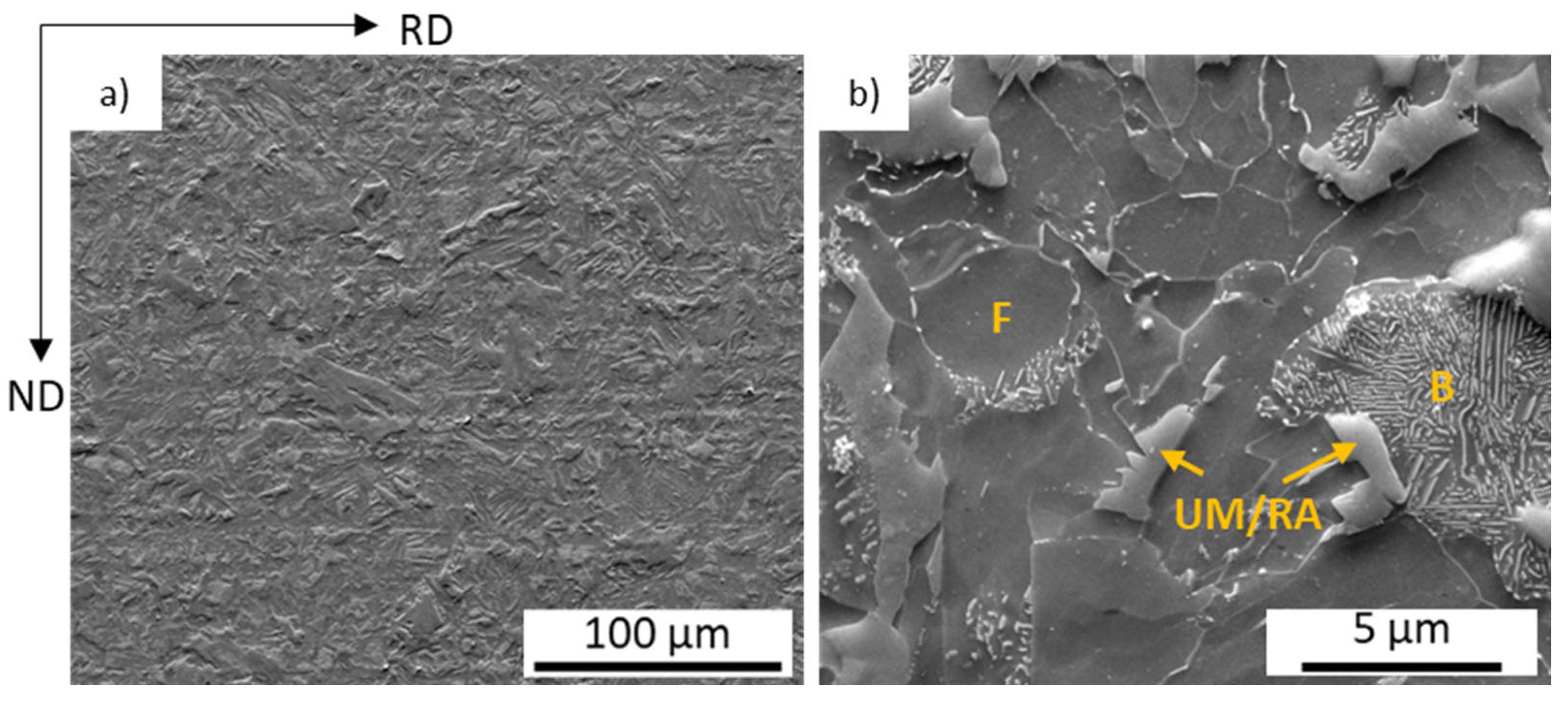
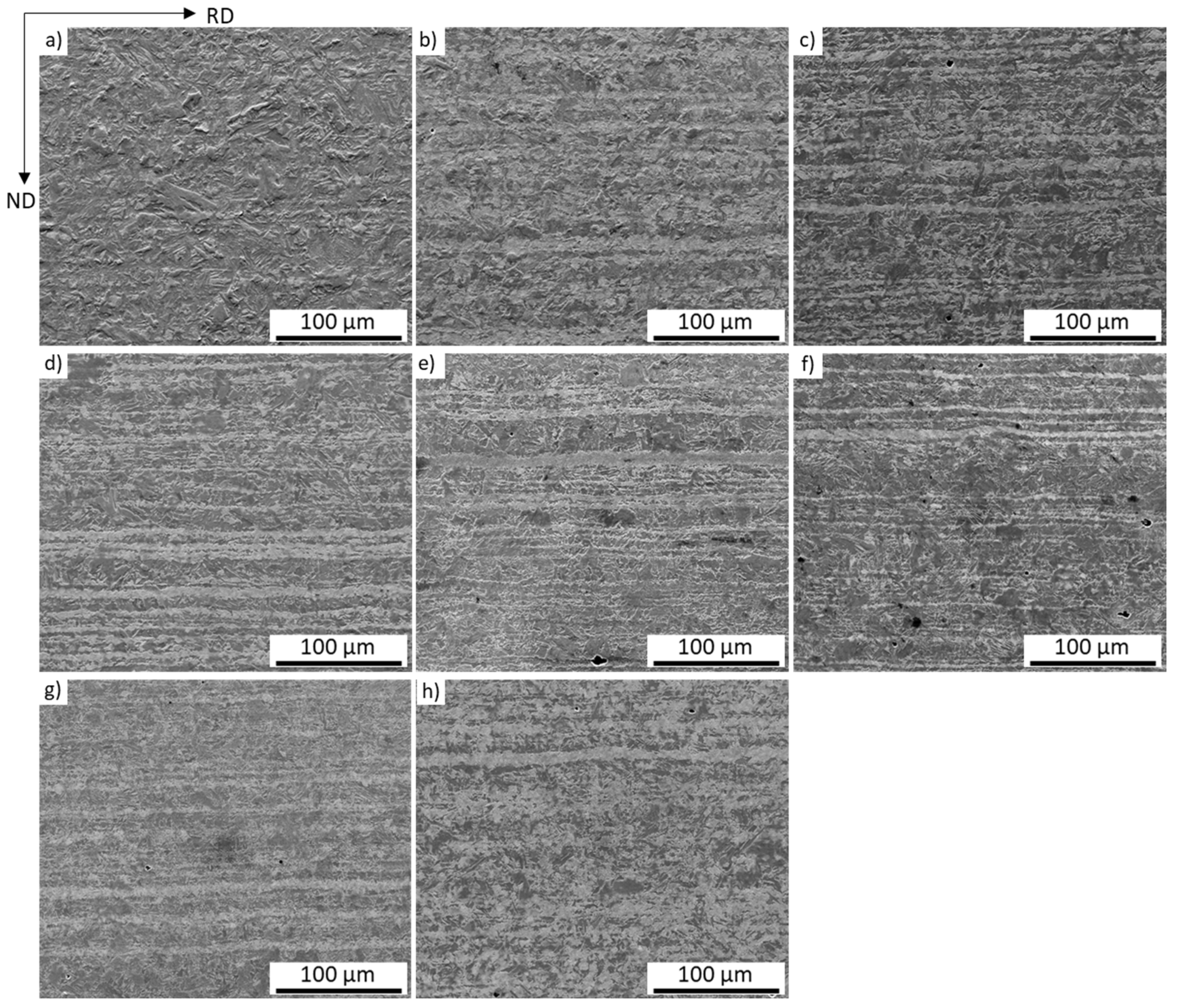
After hot rolling and coiling, the microstructure of the initial material (IM) consists of well-defined ferrite (F) areas and areas with mixtures of bainite and pearlite (B), as well as small islands of untempered martensite and/or retained austenite (UM/RA) (Figure 2b). A general view of the formation of the banded microstructures is shown in Figure 3a–h. SE-SEM images of the steel after thermal cycling obtained at a 1000× magnification (Figure 3b–h) show a banded structure, which was not observed clearly in the initial material (Figure 3a). However, some evidence of bands in the rolling direction could be found. These bands become visible in the TC1 sample (Figure 3b) and the FH sample even without thermal cycling (Figure 3h). The most regular bands are found in TC2 to TC7 and TC7 + FH. Ghaemifar et al. [22] also reported the refinement of the banded structure via thermal cycling. It could be hypothesized that these bands result from preferred nucleation sites for austenite, most likely in regions enriched in C and Mn or near subgrains in unrecrystallized or partially recrystallized ferrite (Figure 3b–h). The same band formation in an initially non-banded structure after thermal cycling was also reported by Li et al. [31] following fast heating, and the band formation was associated with Mn segregation. The effect of preferential nucleation on the subgrain boundaries in partially recrystallized structures should not be excluded, as far as the subgrain boundaries are effective diffusional channels, and they can accelerate the diffusion of fast-diffusing elements like C and not-so-fast-diffusing elements like Mn in these regions [32,33,34,35,36]. Hence, both effects can be considered responsible for the band formation in the initially homogeneous microstructure.
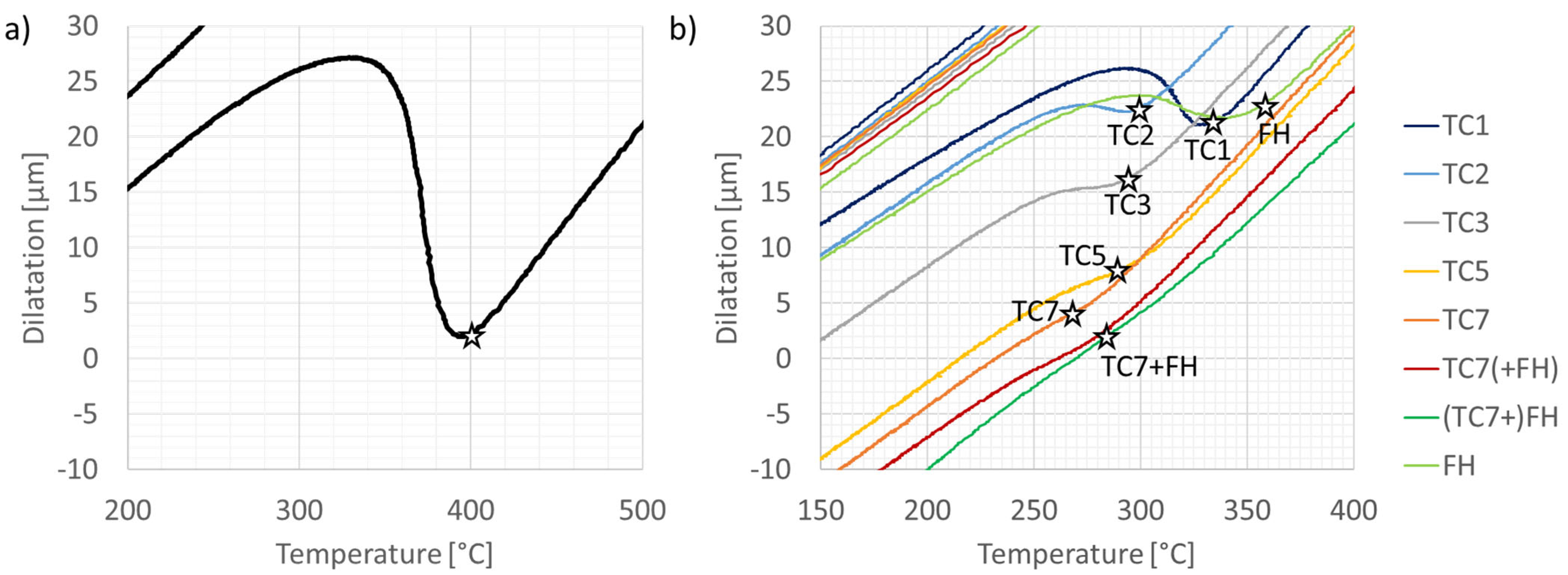
Additionally, the dilatometric data for the phase transformation showed variations in the transformation temperatures as a function of the number of thermal cycles. Most visible are these changes in the Ms temperature, which changes from 400 °C for the subsequently quenched sample after complete austenitization (Figure 4a) to 260 °C for samples after seven thermal cycles following partial (50%F + 50%A) austenitization (TC7), as shown in Figure 4b.
The decrease in the dilatation effects observed in Figure 4 is associated with the increase in the number of thermal cycles. This effect is very clear when comparing the sharpness of the curvature of the dilatometric curve at the Ms temperature shown in Figure 4b. After three, five, and seven thermal cycles, the martensitic transformation peaks are not as clear as after the first and second cycles, which indicates a small transformed fraction of intercritical austenite.
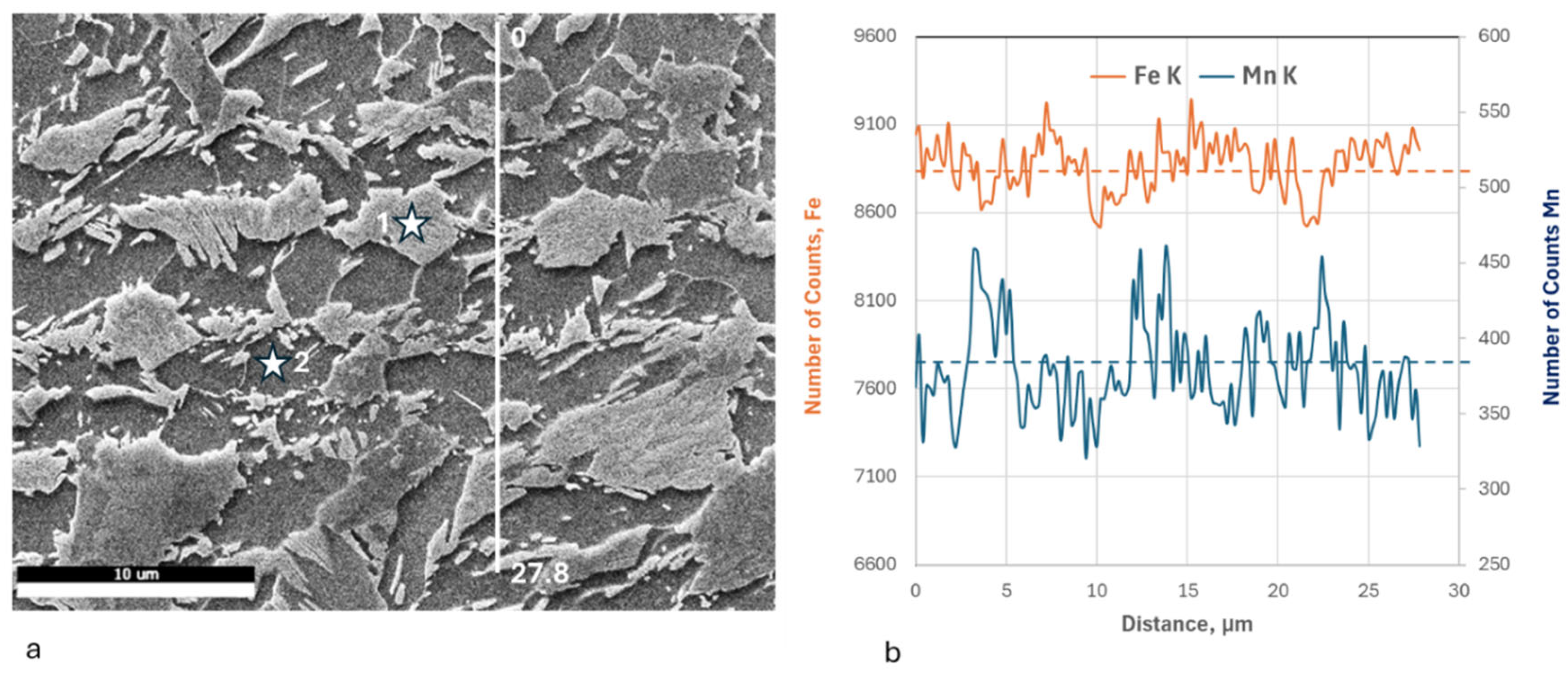
The Ms temperature changes are a clear indication that the intercritical austenite that transforms during cooling has a different composition, which varies with the number of thermal cycles. Most likely, the intercritical austenite becomes increasingly enriched with C and Mn as the number of thermal cycles increases. To test this hypothesis, EDS measurements have been carried out on all samples, and Figure 5 shows representative data for the chemical composition measured by a line scan using the Fe and Mn Kα peaks, with data from the EDS quantitative analyses at specific points added.
The EDS data very clearly show the distribution of Mn and Fe, from which one can conclude that the zones in the microstructure that contain B-M-RA are enriched in Mn with respect to the neighboring ferrite zone (Figure 5b). The point measurements shown in Figure 5a are an example, from which the Mn content in points 1 and 2 is calculated as 2.61 mass% Mn for point 1 and 1.94 mass% Mn for point 2 in ferrite. The numbers mentioned above are averages of at least three individual measurements in these zones.
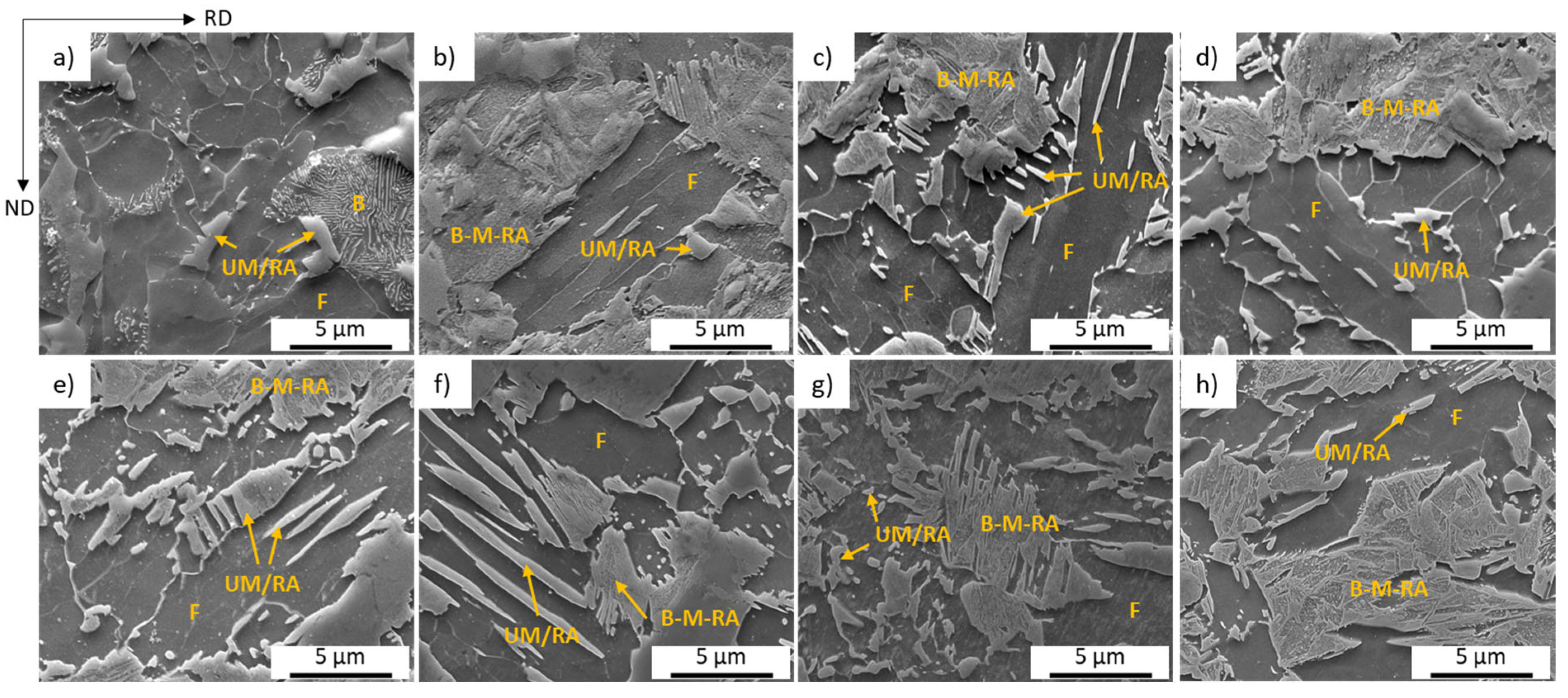
Higher-magnification SEM images (Figure 6a–h) show that the microstructure after thermal cycling is a combination of ferrite, martensite, bainite, and, possibly, retained austenite. The observed bands are alternating regions of ferrite and B-M-RA bands, where B-M-RA stands for a combination of bainite, martensite, and retained austenite. These microstructures were also shown in Figure 2. The formation of the complex structure observed in the B-M-RA bands is attributed to the heterogeneity of the local chemical composition, which was discussed above. This is due to the formation of ferrite immediately after cooling, which requires the surrounding austenite to absorb large amounts of carbon. This heterogeneous distribution of carbon results in different transformation behaviors within a small region, leading to a complex microstructure that cannot be uniquely defined as bainite or martensite [37,38,39,40,41]. This difference in the transformation behavior could also explain the decrease in Ms temperature observed in the dilatometer test. Apart from the bands, B-M-RA islands can also be found within ferrite matrices, and their appearance can be associated with nucleation of austenite at ferrite subgrain boundaries. This phenomenon occurs more frequently in TC2 to TC7 and TC7 + FH.
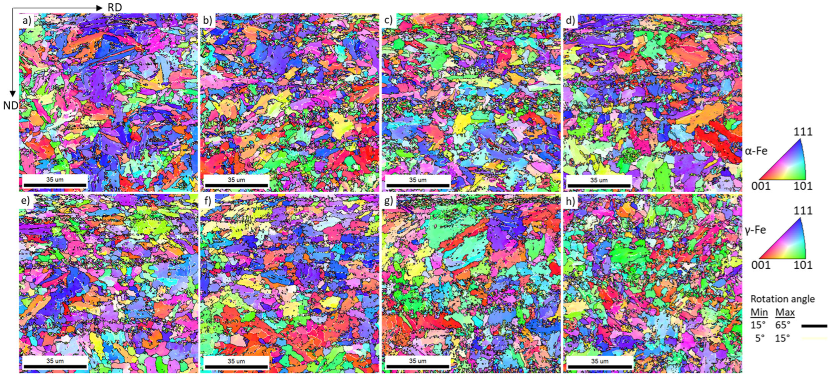
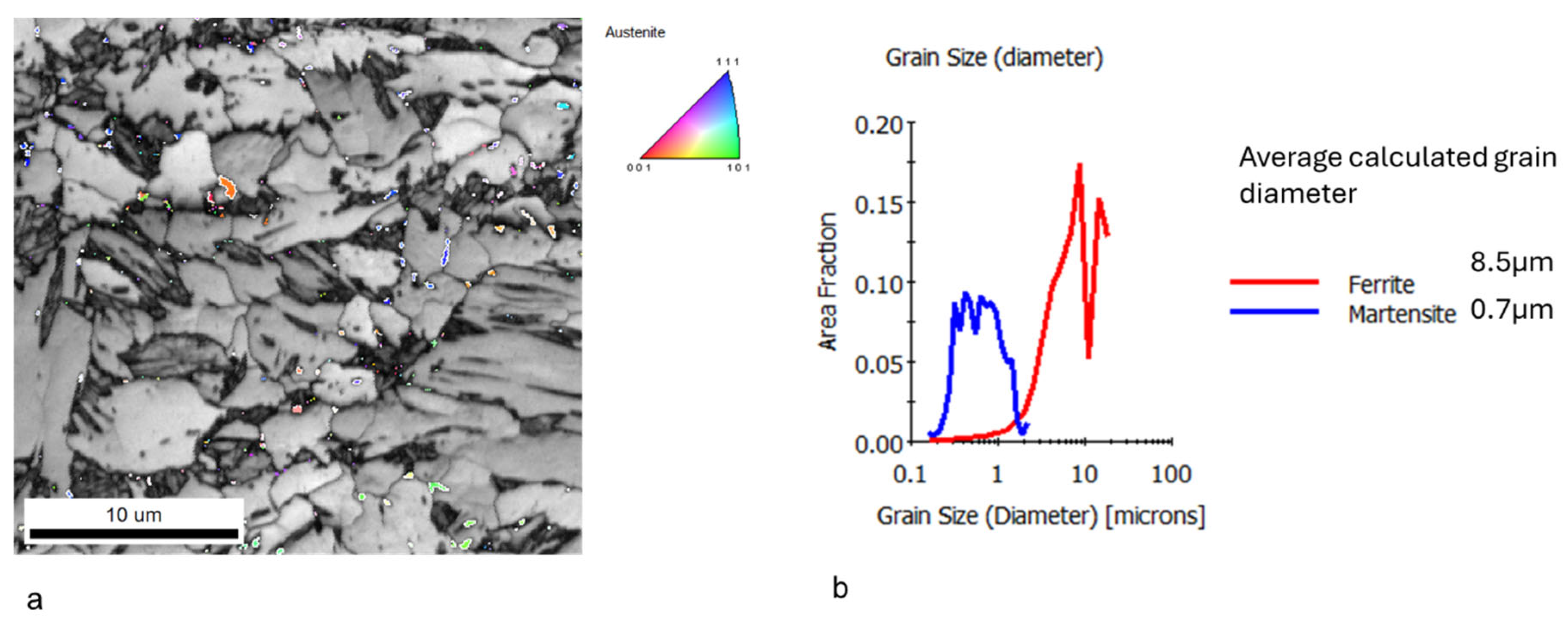
The data from the EBSD analysis is shown in Figure 7. These maps display the normal direction (ND) inverse pole figures (IPF) for the IM and the TC(i) (i = 1–7) samples. The crystallographic orientations of both body-centered cubic (BCC) and face-centered cubic (FCC) phases were presented. Although this representation makes it difficult to identify retained austenite (FCC) on these maps, it is clearly visible on the combined EBSD image quality (IQ) and IPF maps of the individual phases, as shown in Figure 8.
The retained austenite fraction in the initial material and heat-treated samples has been calculated from the EBSD phase maps, and it does not exceed 1 vol.% in any sample.
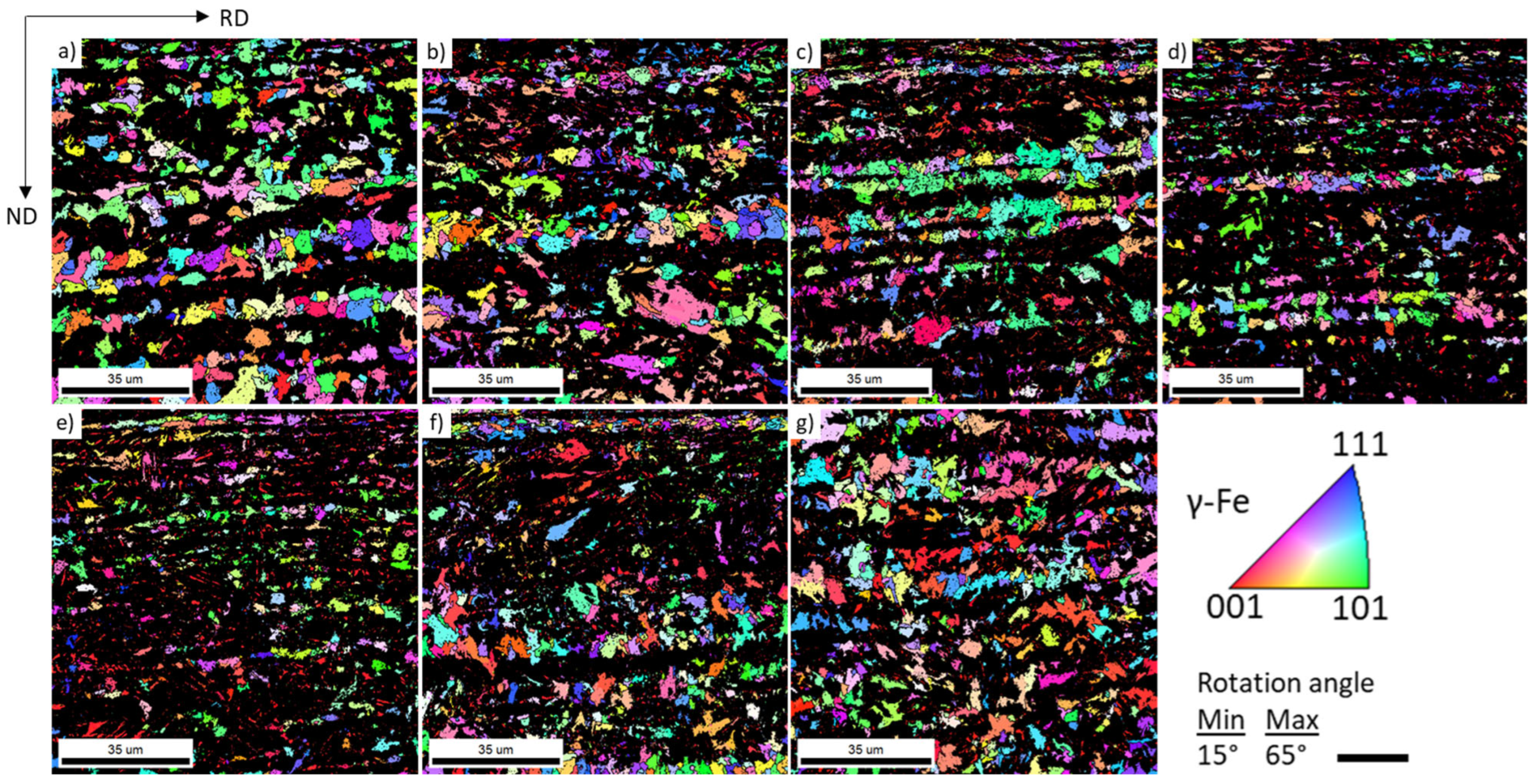
The zones in the microstructure that contain martensite, bainite, and retained austenite, which appear dark in Figure 8, were separated from the ferritic zones using the approach for quantifying the grain average image quality (GAIQ) reported elsewhere [42,43,44]. These data have also been quantified, and the fractions of the F and B-M-RA are shown in Table 4. These data have been extracted from the entire EBSD scan and used to reconstruct the prior austenite grains in specific regions where the phase transformation from intercritical austenite to martensite (bainite) occurred. For the reconstruction, the K-S orientation relationship was employed, and the ND-IPF maps of the reconstructed prior austenite grains (PAGs) are presented in Figure 9. The results of this quantification are also summarized in Table 4.
The data presented in Figure 9 and Table 4 indicate that thermal cycling has a significant grain-refining effect on the PAGs. The increase in the number of thermal cycles from one to seven corresponds to a decrease in the PAGs from 19 µm to 5 µm (Table 4). These data show that the PAGs do not directly influence the hardness of the final structure; however, the area fraction of (B-M-RA) formed from these intercritical austenite islands is more influential on the properties.
The data from Table 4 are also represented graphically in Figure 10.
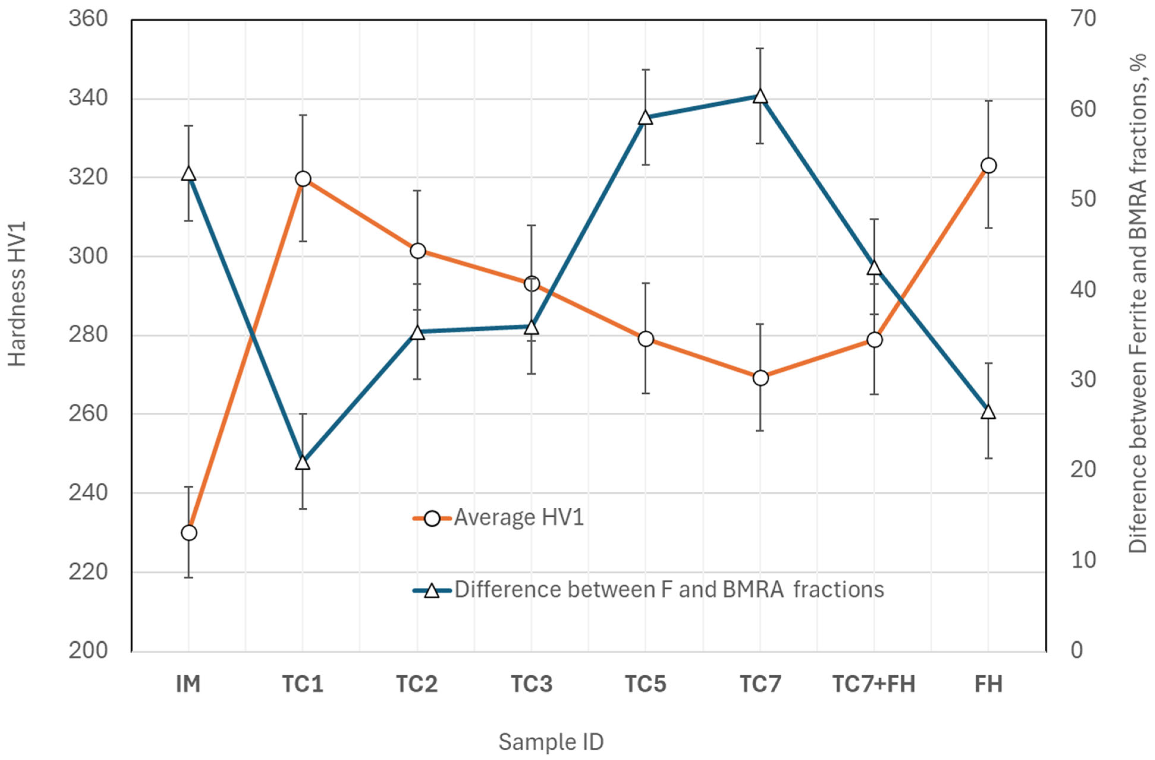
The results shown in Table 4 and Figure 10 indicate a clear tendency for the hardness of the samples to decrease as the number of thermal cycles increases from one to seven. The decrease in hardness with additional thermal cycles was also reported in [45]. Suppose these variations are considered in conjunction with the changes in the fraction of microstructural constituents. In that case, it appears that the decrease in hardness in the samples can be attributed to variations in the ferrite fractions and the fraction of B-M-RA constituents. Still, they are not very sensitive to variations in the ferrite grain size. These three parameters—ferrite fraction, B-M-RA, and average ferrite grain size—depend on and can be controlled via thermal cycling, but a closer look at the data shows that the balance between the fractions of (F) and (B-M-RA) is the most important parameter that is responsible for the hardness (Figure 11).
To express this dependence, the data for the difference between the fractions of ferrite (both the intercritical one and the one that may form during the cooling) and the fraction of (B-M-RA) quantified via the EBSD measurements are plotted in Figure 11. The numbers in Figure 11 show the difference between the volume fraction of ferrite and (B-M-RA) and are calculated by using the following simple formula:
ΔVf = Vf(F)Vf(B-M-RA), [%],
where Vf means volume fraction.
It is very clear that if this difference is in the range of 20% to 30% (predominantly “hard” constituents are presented in the structure), the hardness increases. It is also important to note that ultrafast heating offers similar possibilities, but in this case, the strong grain-refining effect contributes to increased hardness. If ultrafast heating is applied to the samples after seven thermal cycles, the grain-refining effect is not pronounced, and the hardness values are lower than those in the UFH-treated or TC1 and TC2 samples.
These results show that when a small number of thermal cycles, up to two cycles, or only the fast-heating cycle (100 °C/s in this case) without isothermal soaking are applied, they can lead to an excellent combination of grain refining and optimum balance between the soft ferrite and the mixture of hard constituents (B-M-RA). Thus, a significant increase in the hardness of the DP steel could be obtained.
Keeping in mind the link between the hardness and the yield strength suggested by [17], the variations in the yield strength for these hardness levels can be from 560 MPa, for the IM, up to 800 MPa for the TC1 sample, and 815 MPa for the FH sample.
However, the technological realization of thermal cycling with one or two cycles in industrial conditions can be relatively straightforward. In contrast, implementing fast heating with heating rates of 100 °C/s or higher requires a different approach, such as transverse induction heating.

3.2. Crystallographic Texture

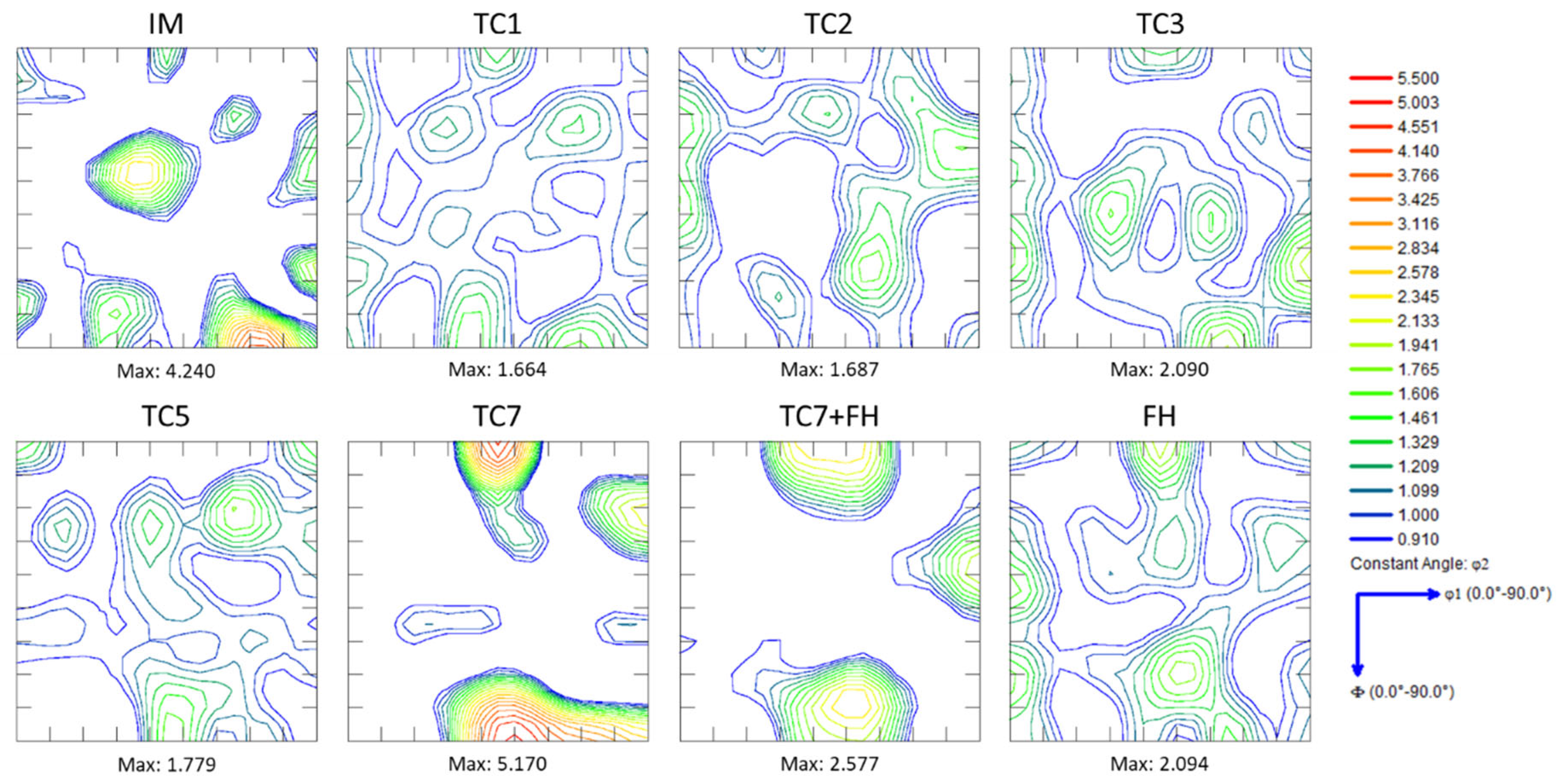
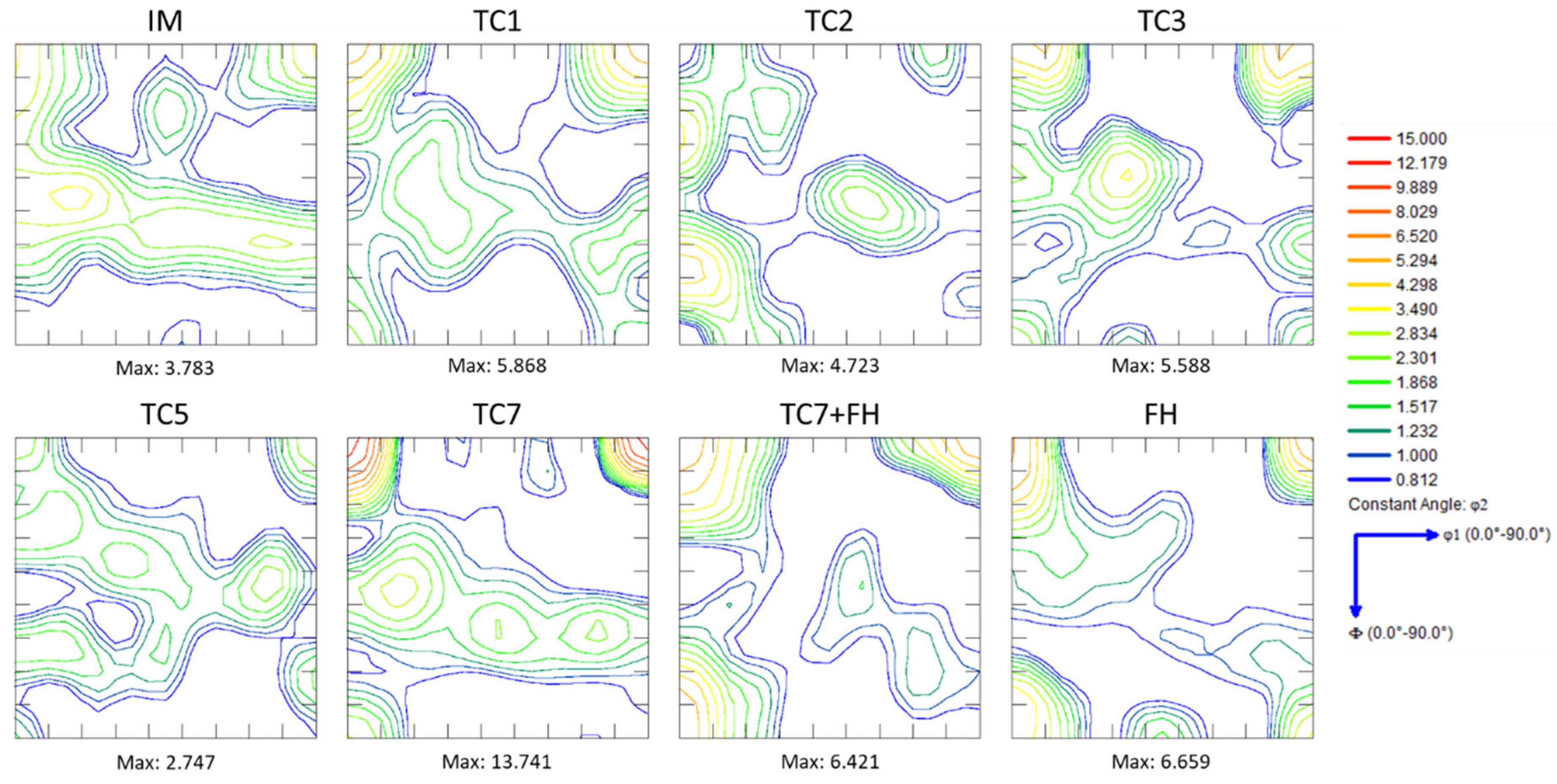
The EBSD data were used to calculate the steel’s textures and to monitor texture evolution after different thermal cycles. Both textures, that of the retained austenite (FCC) (Figure 12) and the BCC microstructural constituents (Figure 13), which include the textures of ferrite, martensite, and bainitic ferrite, have been measured and represented as orientation distribution functions represented in Bunge notation in the Phi2 = 45° section of the Euler space. In all cases, the orthorhombic sample symmetry was applied to the individual orientation data, taking into account that the samples were processed by hot rolling.
The texture of the retained austenite of the IM contains typical representatives of the FCC deformation texture component with a pronounced intensity of 4.2×mrd (multiples of random density) in the region between the brass {111}<112> and Goss {110}<001> texture components, together with ~1.6×mrd on the copper {112}<111> texture component. After multiple-phase transformation during thermal cycling, the FCC texture initially weakens. Still, after seven thermal cycles (sample TC7), the texture strengthens again, showing a maximum of 5.4×mrd on the cube {001}<100> texture component, which is typical for the recrystallized austenite, and equal intensity on the brass {111}<112> (5.4×mrd) and a weaker intensity of 2.1×mrd on the copper {112}<111> texture component. This means that the intercritical austenite is likely to have recrystallized partially during the thermal cycles. It should be mentioned that this strengthening of the texture might be a consequence of the decreased total fraction of retained austenite after seven cycles and, consequently, the number of the measured crystallographic orientations.
The BCC texture components shown in Figure 13 are a good example of transformation textures and are in good agreement with existing knowledge. They follow quite well the transformation textures model suggested by Jonas in [46].
The analysis of the BCC textures of the IM shows typical transformation fibers originating from austenite with brass and copper orientations. After thermal cycling, the BCC texture components with rotated cube ({001}<110>) orientation, which may originate from recrystallized austenite with cube orientation {001}<100> or brass orientation, and rotated Goss {110}<110> and Goss {110}<001>, are clearly present in the textures of samples TC1, TC3, TC5, and TC7. These changes in transformation textures suggest that during thermal cycling, the ferrite recrystallized. It is essential to note that even rapid heating at 100 °C/s without isothermal soaking still allows partial recrystallization of both ferrite and austenite. The formation of texture components, such as a rotated cube ({100}<011>) in combination with Goss and rotated Goss, is not ideal, considering the deep drawability of DP steel.

4. Summary and Conclusions

  • The hardness of dual-phase (DP) steel is primarily governed by the balance between ferrite and the transformation products—bainite, martensite, and retained austenite (B-M-RA)—which can be effectively tailored through thermal cycling. The ferrite grain size has only a secondary influence on hardness.
  • Thermal cycling produces a pronounced grain-refining effect in both the prior austenite grains (PAGs) and the B-M-RA structures, with refinement intensifying as the number of cycles increases. However, excessive cycling or the addition of a fast-heating (FH) step after multiple cycles leads to grain coarsening. Ferrite grain size shows no consistent trend but tends to increase after several cycles, while FH samples consistently exhibit the smallest overall grain sizes.
  • Repeated thermal cycling enhances carbon and manganese diffusion toward transformed regions, resulting in the formation of banded microstructures and a reduction in the martensite start (Ms) temperature due to solute enrichment of intercritical austenite. Crystallographic texture analysis further indicates recrystallization of both BCC and FCC constituents, even at rapid heating rates of 100 °C/s.
  • Mechanical properties, particularly hardness and yield strength, can be improved by applying up to two thermal cycles or by employing fast heating without isothermal soaking. Increasing the number of cycles beyond this point reduces the B-M-RA fraction due to higher Ac1 temperatures and enhanced ferrite formation during cooling.
The overall results demonstrate that thermal cycling is a viable and flexible alternative to conventional heat treatments for DP steels, allowing precise tuning of mechanical properties through controlled thermal parameters. However, a successful industrial application will require careful optimization of continuous annealing line conditions to ensure consistent performance and microstructural stability.

Author Contributions

Conceptualization, R.H.P. and A.B.; methodology, R.H.P. and A.B.; validation, J.F.A. and A.B.; investigation, J.F.A., A.B. and R.H.P.; resources, R.H.P.; data curation, R.H.P.; writing—A.B. and J.F.A.; preparation, A.B. and J.F.A.; writing—review and editing, R.H.P. and A.B.; supervision, R.H.P.; project administration and funding acquisition, R.H.P. All authors have read and agreed to the published version of the manuscript.

Funding

This research received no external funding.

Data Availability Statement

The original contributions presented in this study are included in the article. Further inquiries can be directed to the corresponding author.

Conflicts of Interest

The authors declare no conflict of interest.

References

  1. Basoeki, P.D. Improving lightweight materials processing for automotive by using intercritical annealing. MATEC Web Conf. 2018, 175, 02023. [Google Scholar] [CrossRef]
  2. Arcelor Mittal North America. Dual Phase Steels. Available online: https://northamerica.arcelormittal.com/media/vtmdpdq2/arcelormittal_data-sheet_dual-phase-steels_2024_x1a.pdf (accessed on 5 September 2025).
  3. Suski, C.A.; Filho, J.F.S.; Cortez, A.; Gonçalves, F.E.; Ferreira, R.R. The environmental impact of lightweight body in white structures in vehicle manufacturing. J. Clean. Prod. 2024, 449, 141833. [Google Scholar] [CrossRef]
  4. Calcagnotto, M.; Ponge, D.; Raabe, D. Effect of grain refinement to 1μm on strength and toughness of dual-phase steels. Mater. Sci. Eng. A 2010, 527, 7832–7840. [Google Scholar] [CrossRef]
  5. Asadi, M.; De Cooman, B.C.; Palkowski, H. Influence of martensite volume fraction and cooling rate on the properties of thermomechanically processed dual phase steel. Mater. Sci. Eng. A 2012, 538, 42–52. [Google Scholar] [CrossRef]
  6. Movahed, P.; Kolahgar, S.; Marashi, S.P.H.; Pouranvari, M.; Parvin, N. The effect of intercritical heat treatment temperature on the tensile properties and work hardening behavior of ferrite–martensite dual phase steel sheets. Mater. Sci. Eng. A 2009, 518, 1–6. [Google Scholar] [CrossRef]
  7. Lu, J.; Yu, H.; Yang, S. Mechanical behavior of multi-stage heat-treated HSLA steel based on examinations of microstructural evolution. Mater. Sci. Eng. A 2021, 803, 140493. [Google Scholar] [CrossRef]
  8. Hernandez-Duran, E.I.; Bliznuk, V.; Ros-Yanez, T.; Iquilio-Abarzua, R.; Castro-Cerda, F.M.; Petrov, R.H. Improvement of the strength-ductility balance in ultrafast heated steels by combining high-temperature annealing and quenching and partitioning process. Mater. Sci. Eng. A 2021, 827, 142045. [Google Scholar] [CrossRef]
  9. Gaggiotti, M.; Albini, L.; Di Nunzio, P.; Di Schino, A.; Stornelli, G.; Tiracorrendo, G. Ultrafast Heating Heat Treatment Effect on the Microstructure and Properties of Steels. Metals 2022, 12, 1313. [Google Scholar] [CrossRef]
  10. Cerda, F.M.C. Third Generation Advanced High Strength Steels via Ultrafast Heating. Ph.D. Thesis, Ghent University, Gent, Belgium, 2017. [Google Scholar]
  11. Banis, A.; Bouzouni, M.; Petrov, R.H.; Papaefthymiou, S. Simulation and characterisation of the microstructure of ultra-fast heated dual-phase steel. Mater. Sci. Technol. 2020, 36, 1282–1291. [Google Scholar] [CrossRef]
  12. Bouzouni, M.; Papaefthymiou, S. Preliminary Study of Carbide Dissolution during an Ultra-Fast Heat Treatment in Chromium Molybdenum Steel. Int. J. Metall. Met. Phys. 2017, 2, 1–7. [Google Scholar] [CrossRef]
  13. Carreno-Saavedra, J.I.; Ros-Yanez, T.; García, C.I.; Hernández-Durán, E.I.; Iquilio, R.A.; Cerda, F.M.C. Application of ultrafast heating and tempering to plate steel. Mater. Sci. Technol. 2023, 39, 2417–2432. [Google Scholar] [CrossRef]
  14. Cryderman, R.L.; Arterbury, E.; Bamrud, F. Effects of Initial Microstructure and Induction Heating Cycle on the Microstructure and Torsional Fatigue Performance of a Steel Containing 0.6 wt pct Carbon. J. Mater. Eng. Perform. 2024, 33, 2680–2693. [Google Scholar] [CrossRef]
  15. Matlock, D.K.; Kang, S.; De Moor, E.; Speer, J.G. Applications of rapid thermal processing to advanced high strength sheet steel developments. Mater. Charact. 2020, 166, 110397. [Google Scholar] [CrossRef]
  16. Pedraza, J.P.; Landa-Mejia, R.; García-Rincon, O.; Garcia, C.I. The Effect of Rapid Heating and Fast Cooling on the Transformation Behavior and Mechanical Properties of an Advanced High Strength Steel (AHSS). Metals 2019, 9, 545. [Google Scholar] [CrossRef]
  17. Grange, R.A. The rapid heat treatment of steel. Metall. Trans. 1971, 2, 65–78. [Google Scholar] [CrossRef]
  18. Konopleva, E.V.; Éntin, R.I.; Bayazitov, V.M.; Kogan, L.I.; Spasskii, M.N. Thermal cycling treatment of low-carbon martensitic-bainitic steels. Met. Sci. Heat. Treat. 1987, 29, 489–492. [Google Scholar] [CrossRef]
  19. Hidalgo, J.; Santofimia, M.J. Effect of Prior Austenite Grain Size Refinement by Thermal Cycling on the Microstructural Features of As-Quenched Lath Martensite. Metall. Mater. Trans. A 2016, 47, 5288–5301. [Google Scholar] [CrossRef]
  20. Hernandez-Duran, E.; Corallo, L.; Ros-Yanez, T.; Castro-Cerda, F.; Petrov, R.H. The Effect of Different Annealing Strategies on the Microstructure Development and Mechanical Response of Austempered Steels. Metals 2021, 11, 1041. [Google Scholar] [CrossRef]
  21. Koo, J.Y.; Thomas, G. Thermal cycling treatments and microstructures for improved properties of Fe-0.12% C-0.5% Mn steels. Mater. Sci. Eng. 1976, 24, 187–198. [Google Scholar] [CrossRef]
  22. Ghaemifar, S.; Mirzadeh, H. Refinement of Banded Structure via Thermal Cycling and Its Effects on Mechanical Properties of Dual Phase Steel. Steel Res. Int. 2018, 89, 1700531. [Google Scholar] [CrossRef]
  23. Ghaemifar, S.; Mirzadeh, H. Enhanced mechanical properties of dual-phase steel by repetitive intercritical annealing. Can. Metall. Q. 2017, 56, 459–463. [Google Scholar] [CrossRef]
  24. Ghaemifar, S.; Mirzadeh, H.; Khorrami, M.S.; Soltani, R.; Nasiri, Z. Improved properties of dual-phase steel via pre-intercritical annealing treatment and thermal cycling. Mater. Sci. Technol. 2020, 36, 1663–1670. [Google Scholar] [CrossRef]
  25. Nasiri, Z.; Ghaemifar, S.; Naghizadeh, M.; Mirzadeh, H. Thermal Mechanisms of Grain Refinement in Steels: A Review. Met. Mater. Int. 2021, 27, 2078–2094. [Google Scholar] [CrossRef]
  26. Ashrafi, H.; Shamanian, M.; Emadi, R.; Saeidi, N. A novel and simple technique for development of dual phase steels with excellent ductility. Mater. Sci. Eng. A 2017, 680, 197–202. [Google Scholar] [CrossRef]
  27. Xie, Z.J.; Han, G.; Zhou, W.H.; Wang, X.L.; Shang, C.J.; Misra, R.D.K. A novel multi-step intercritical heat treatment induces multi-phase microstructure with ultra-low yield ratio and high ductility in advanced high-strength steel. Scr. Mater. 2018, 155, 164–168. [Google Scholar] [CrossRef]
  28. Craeynest, A. Experimental Study & Simulations of the Transformation Behavior of Dual-Phase Steels. Master’s Thesis, Ghent University, Gent, Belgium, 2022. [Google Scholar]
  29. Fujita, M.; Kuki, K. An Evaluation of Mechanical Properties with the Hardness of Building Steel Structural Members for Reuse by NDT. Metals 2016, 6, 247. [Google Scholar] [CrossRef]
  30. Xu, X.; van der Zwaag, S.; Xu, W. The effect of martensite volume fraction on the scratch and abrasion resistance of a ferrite–martensite dual phase steel. Wear 2016, 348–349, 80–88. [Google Scholar] [CrossRef]
  31. Li, P.; Li, J.; Meng, Q.; Hu, W.; Xu, D. Effect of heating rate on ferrite recrystallization and austenite formation of cold-roll dual phase steel. J. Alloys Compd. 2013, 578, 320–327. [Google Scholar] [CrossRef]
  32. HajyAkbary, F.; Sietsma, J.; Petrov, R.H.; Miyamoto, G.; Furuhara, T.; Santofimia, M.J. A quantitative investigation of the effect of Mn segregation on microstructural properties of quenching and partitioning steels. Scr. Mater. 2017, 137, 27–30. [Google Scholar] [CrossRef]
  33. Zhang, D.; Li, H.; Song, Y.; Sun, H.; Zheng, Y.; Ma, C.; She, Y.; Wang, B.; Yang, S. Toughness and plasticity mechanism of medium manganese steel in cyclic phase transformation strengthening. J. Mater. Sci. 2025, 60, 4897–4914. [Google Scholar] [CrossRef]
  34. Celotto, S.; Ghadbeigi, H.; Pinna, C.; Shollock, B.A.; Efthymiadis, P. Deformation-Induced Microstructural Banding in TRIP Steels. Metall. Mater. Trans. A 2018, 49, 2893–2906. [Google Scholar] [CrossRef]
  35. Petrov, R.; Kestens, L.; Houbaert, Y. Recrystallization of a Cold Rolled Trip-assisted Steel during Reheating for Intercritical Annealling. ISIJ Int. 2001, 41, 883–890. [Google Scholar] [CrossRef]
  36. Thomas, L.S.; Matlock, D.K. Formation of Banded Microstructures with Rapid Intercritical Annealing of Cold-Rolled Sheet Steel. Metall. Mater. Trans. A 2018, 49, 4456–4473. [Google Scholar] [CrossRef]
  37. Gulyaev, A. Physical Metallurgy; Mir Publishers: Moscow, Russia, 1980; Volume 1, p. 173. Available online: https://books.google.gr/books?id=fYNkwAEACAAJ (accessed on 8 October 2025).
  38. Gulyaev, A. Physical Metallurgy; Mir Publishers: Moscow, Russia, 1980; Volume 2, p. 23. Available online: https://books.google.gr/books?id=Vm6NzwEACAAJ (accessed on 8 October 2025).
  39. Sohrab, S.H.; Catrakis, H.J.; Kobasko, N. Recent Advances in Heat Transfer, Thermal Engineering and Environment; WSEAS Press: Stevens Point, WI, USA, 2009. [Google Scholar]
  40. Skowronek, A.; Radwański, K.; Sozańska-Jędrasik, L.; Matus, K.; Grajcar, A. Continuous annealing of medium-Mn steels: Sensitivity of mechanical performance to minor changes in time-temperature heat treatment parameters. Mater. Sci. Eng. A 2025, 940, 148568. [Google Scholar] [CrossRef]
  41. Skowronek, A.; Grajcar, A.; Kozłowska, A.; Janik, A.; Morawiec, M.; Petrov, R.H. Temperature-Dependent Microstructural Evolution of Al-Rich Medium-Mn Steel During Intercritical Annealing. Metall. Mater. Trans. A 2022, 53, 3012–3021. [Google Scholar] [CrossRef]
  42. Colás, R.; Totten, G.E. (Eds.) Encyclopedia of IRON, Steel, and Their Alloys; CRC Press: Boca Raton, FL, USA, 2016. [Google Scholar] [CrossRef]
  43. Davut, K.; Zaefferer, S. Statistical Reliability of Phase Fraction Determination Based on Electron Backscatter Diffraction (EBSD) Investigations on the Example of an Al-TRIP Steel. Metall. Mater. Trans. A 2010, 41, 2187–2196. [Google Scholar] [CrossRef]
  44. Zaefferer, S.; Ohlert, J.; Bleck, W. A study of microstructure, transformation mechanisms and correlation between microstructure and mechanical properties of a low alloyed TRIP steel. Acta Mater. 2004, 52, 2765–2778. [Google Scholar] [CrossRef]
  45. Farshchi, Y.K.; Mirzadeh, H.; Tavakoli, M.; Zamani, M. Microstructure tailoring for property improvements of DP steel via cyclic intercritical annealing. Mater. Res. Express 2019, 6, 126513. [Google Scholar] [CrossRef]
  46. Jonas, J.J. Transformation Textures Associated with Steel Processing; Haldar, A., Suwas, S., Bhattacharjee, D., Eds.; Microstructure and Texture in Steels; Springer: London, UK, 2009; pp. 3–17. [Google Scholar] [CrossRef]
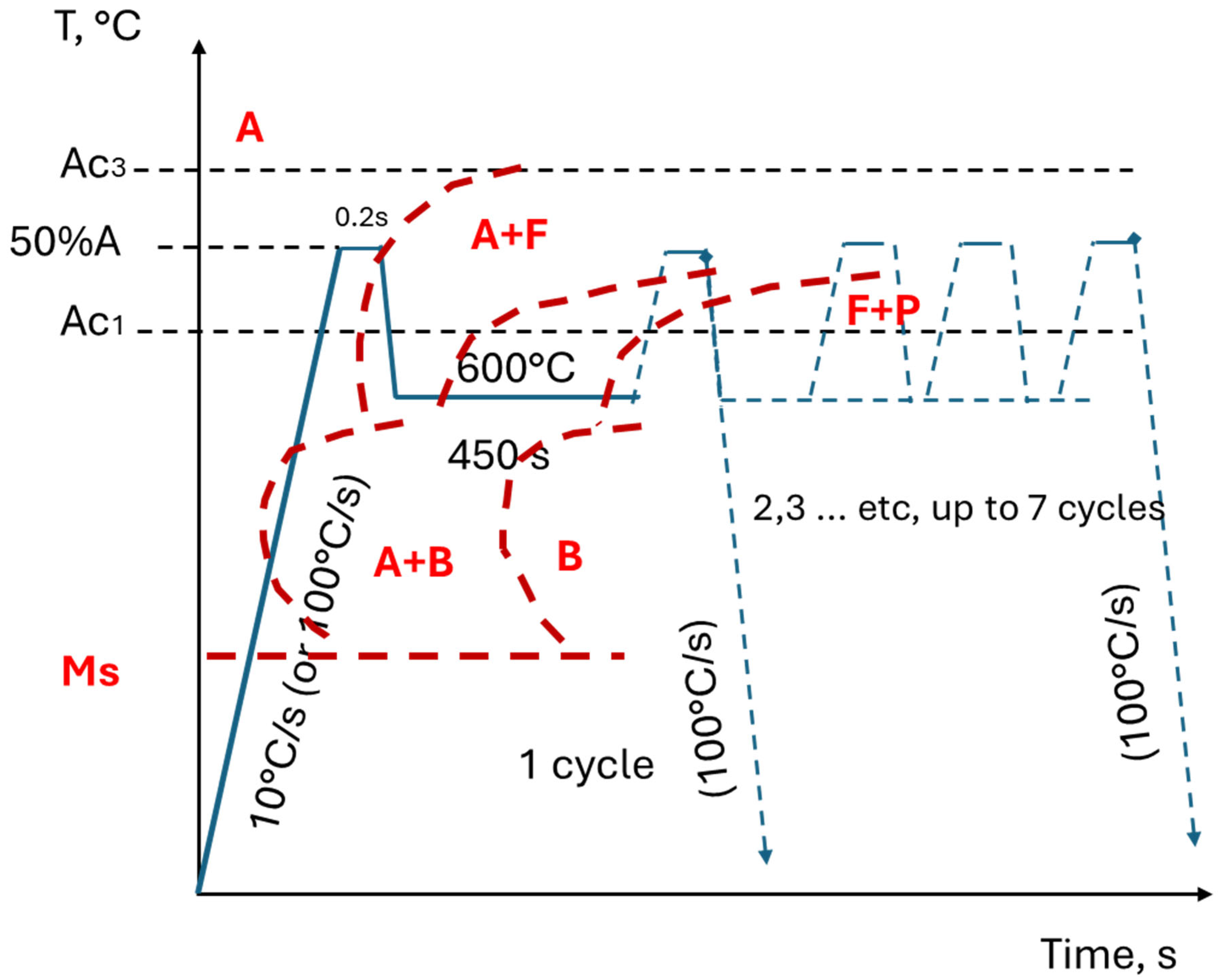
Figure 1. Heat treatment cycles used in this work. The blue lines show one heat treatment cycle. The red dotted lines schematically represent the time–temperature–transformation (TTT) diagram of the steel used in this work, illustrating the transformation for an initial state of 50% ferrite and 50% austenite. One cycle involves heating to the intercritical temperature range, isothermal holding for 450 s at 600 °C, heating again to the intercritical range with a 50% ferrite and 50% austenite composition, and quenching at 100 °C/s.
Metals 15 01230 g001
Figure 2. Microstructure of the DP steel after hot rolling and coiling. The white rectangle in (a) corresponds approximately to the zone of observation shown in (b), where F is Ferrite, B—mixture of bainite and pearlite, UM—untempered martensite, and RA—retained austenite.
Metals 15 01230 g002
Figure 3. SE-SEM-images of IM (a), TC1 (b), TC2 (c), TC3 (d), TC5 (e), TC7 (f), TC7 + FH (g), and FH (h) at 1000× magnification.
Metals 15 01230 g003
Figure 4. (a) Dilatometric curve from the cooling stage with a cooling rate of 100 °C/s for a sample IM after complete austenitization and quenching with >100 °C/s; (b) Ms temperatures for the samples after multiple partial re-austenitization in the intercritical temperature ranges with 50% F + 50% A, and different numbers of thermal cycles are marked with stars.
Metals 15 01230 g004
Figure 5. (a) SE-SEM image of sample TC7. The white line indicates the path along which the line scan was performed. Point 1 is in the zone where B-M-RA exists, point 2 is in the entirely ferritic grain; (b) signal level for Fe (orange line) and Mn (blue line) along the white line in (a), expressed as number of counts.
Metals 15 01230 g005
Figure 6. SE-SEM images of (a) IM, (b) TC1, (c) TC2, (d) TC3, (e) TC5, (f) TC7, (g) TC7 + FH, and (h) FH at 16,000× magnification with indications of the microstructure (F = ferrite, B = bainite, UM/RA = untempered martensite/retained austenite, and B-M-RA = bainite, martensite, retained austenite, or a combination).
Metals 15 01230 g006
Figure 7. ND-Inverse Pole Figure maps of (a) IM, (b) TC1, (c) TC2, (d) TC3, (e) TC5, (f) TC7, (g) TC7 + FH, and (h) FH.
Metals 15 01230 g007
Figure 8. (a) Image Quality (IQ) map of sample TC7 combined with an ND-IPF map of retained austenite over-imposed. White lines display the Kurdjumov–Sachs (K-S) axes-angle grain boundaries (<112> 90°) between the RA and the martensitic crystals; (b) chart displaying average calculated grain diameter of martensite (blue line) and ferrite (red line) from the orientation data displayed on Figure 7f.
Metals 15 01230 g008
Figure 9. ND-IPF maps of PAGs calculated from the B-M-RA datasets of (a) TC1, (b) TC2, (c) TC3, (d) TC5, (e) TC7, (f) TC7+FH, and (g) FH.
Metals 15 01230 g009
Figure 10. Graphical representation of the hardness (HV1) and quantitative characteristics of the microstructure (fraction of microstructural constituents and average calculated grain size), based on EBSD data analysis. The measurement error does not exceed 5%, but the error bars are not explicitly shown on the chart to avoid overloading and making it difficult to read.
Metals 15 01230 g010
Figure 11. Difference between the ferrite fraction and the fraction of B-M-RA (blue line with triangle markers) and the hardness of the steel (orange line with circles). The lines in this graph are used only to illustrate the tendency more clearly.
Metals 15 01230 g011
Figure 12. ODFs of the texture of the retained austenite in the steel samples after different numbers of thermal cycles. Phi2 = 45°.
Metals 15 01230 g012
Figure 13. ODFs of the texture of the BCC structural constituents in the steel samples after different numbers of thermal cycles. Phi2 = 45°.
Metals 15 01230 g013
Table 1. Chemical composition (in wt.%) of the steel used in this work. Fe content is the balance to 100 wt.%. The weight fractions of the elements N, Ni, and Cu are below the detection limit, and, as stated in the manufacturer’s datasheet, the corresponding fields are empty (-).
CMnSiCrAlTiV
0.10–0.151.7–2.00.15–0.200.15–0.200.02–0.040.02–0.04<0.005
SnNbNPNiSCu
<0.003<0.002-<0.05-<0.05-
Table 2. Transformation temperatures as a function of the heating rate.
Heating RateAc1 (°C)Ac3 (°C)T50%austenite (°C)
10 °C/s744824788
100 °C/s757840807
Table 3. The parameters of the thermal treatment.
Sample ReferenceHeating Rate (°C/s)Tpeak (°C)tsoak (s)Cooling Rate (°C/s)Thold (°C)thold (s)Quenching Rate (°C/s)
TC(i)
For i = 1–7
107880.220600450>100
FH1008070.2---100
Table 4. Fractions of ferrite and B-M-RA, together with the average calculated grain diameter and hardness (HV1). GS stands for grain size, referring to the grain diameter measured by EBSD. The standard error of the hardness measurements is also provided.
Sample IDIMTC1TC2TC3TC5TC7TC7 + FHFH
B-M-RA, [%]2440323220192937
Ferrite, [%]7761686880817163
AvgGS_ F, [µm]1489712810110428119372
AvgGS B-M-RA, [µm]115332235
AvgGS PAGs, [µm] 192119851120
Avg hardness, HV1230 ± 1320 ± 2302 ± 4293 ± 5279 ± 3269 ± 3279 ± 6323 ± 3
Disclaimer/Publisher’s Note: The statements, opinions and data contained in all publications are solely those of the individual author(s) and contributor(s) and not of MDPI and/or the editor(s). MDPI and/or the editor(s) disclaim responsibility for any injury to people or property resulting from any ideas, methods, instructions or products referred to in the content.