Article

Die Design for Extrusion Process of Titanium Seamless Tube Using Finite Element Analysis

1
Technical Support Team, Forge Master Korea, Changwon 51395, Korea
2
Department of Materials AI & Big Data, Korea Institute of Materials Science, Changwon 51508, Korea
3
School of Mechanical Engineering, Pusan National University, Busan 46241, Korea
4
School of Mechanical Engineering, University of Ulsan, Ulsan 44610, Korea
*
Author to whom correspondence should be addressed.
Metals 2021, 11(9), 1338; https://doi.org/10.3390/met11091338
Submission received: 30 July 2021 / Revised: 12 August 2021 / Accepted: 19 August 2021 / Published: 25 August 2021
(This article belongs to the Special Issue Computational Advanced Metallic Materials Processing)

Abstract

:
In this paper, the extrusion process of titanium seamless tubes was studied using several finite element (FE) analyses. First, the finite element result was compared with experimental extrusion data acquired to validate the current analysis. Then, the effect of design parameters of the die shape was numerically analyzed using commercial FE software, Forge NxT, for the metal forming process. Elastic FE analyses were also conducted for dies to analyze the maximum principal stress that affects the early fracture of dies during the extrusion process and the maximum von Mises stress that causes the severe deformation of dies. Consequently, the effect of the corner radius at the exit and land length on the extrusion load and die stress is negligible compared to that of the corner radius at the entrance and die angle. Finally, we suggested a die angle of 60° and a corner radius at the die entrance between 10 and 15 mm as an optimal design for the current extrusion process.

1. Introduction

Titanium tube is widely used for industrial applications such as desalination plants due to its high resistance to heat and corrosion [1]. In particular, the titanium welded pipe mainly used in the plant market has a disadvantage in that the corrosion resistance is rapidly lowered due to the occurrence of stress corrosion cracking [2] at the weld. These challenges have led to a sharp increase in interest in titanium seamless tube production using manufacturing processes such as rolling, extrusion, drawing, and piercing. The extrusion process is one of the most widely used processes due to the excellent mechanical properties of the product induced by grain refinement [3,4] and high productivity.
However, high pressure is required to use various materials in this process. The porthole extrusion of soft materials such as aluminum [5,6,7,8,9,10] and magnesium [11,12] that are easy to deform and the extrusion of materials with high formability, such as steel [13,14], have been actively studied. However, studies on the tube extrusion of titanium are extremely rare due to the breakage of the dies due to high deformation resistance and the limitation of the equipment capacity.
Udagawa et al. [15] studied the effect of process parameters such as tool geometry and temperature, initial billet temperature, characteristics of the extrusion press, and lubrication on metal flow during the extrusion of titanium alloy tube. They concluded that the control of the temperature is important as the billet generates heat by deformation. Srinivasan et al. [16] investigated the influence of the die half-angle during the containerless titanium tube extrusion process. As a result, it was found that the optimal angle of the die is approximately 30°. Srinivasan conducted a study to find the optimal angle of the extrusion of pure titanium tubes. In addition, Flitta and Sheppard [17] show that the presence of DMZ in the hot extrusion process interferes with the material flow during extrusion. Gattmah et al. [18] investigated the effect of process parameters on the hot extrusion of the hollow aluminum tubes by finite element analysis. They concluded that the surface temperature is increased with increasing ram displacement, friction coefficient, and reduction in area and decreased gradually at the exit of the die due to heat transfer within the surrounding environment. Hansson and Jansson [13] analyzed the tube extrusion of stainless steel after induction heating by using finite element analysis. They successfully predict the load–displacement curves and derived the optimal design to lower the extrusion load. Guo [19] studied dynamic recrystallization during the extrusion of stainless pipe. Li et al. [20] analyzed extrusion parameters to find optimal conditions in the titanium extrusion process. The maximum temperature rise occurs at the die–billet interface. Mirahmadi et al. [21] investigated the temperature and force of extrusion according to process parameters such as ram speed and billet temperature.
Shin et al. [22] analyzed the backward extrusion process of titanium alloy through finite element analysis to study the effects of friction, speed, and mold shape. Ammu et al. [23] developed a systematic method for optimizing the bearing lengths for uniform exit velocity and temperature distribution across a profile. Zhou et al. [24] investigated the effects of die land length and geometry on curvature during sideways extrusion.
Although there are extensive studies on tube extrusion, studies on titanium tube extrusion considering die stress are scarce. Therefore, in this paper, the extrusion process of titanium seamless tubes was studied using several finite element (FE) analyses. First, the finite element result was compared with experimental extrusion data acquired to validate the current analysis. Then, the effect of design parameters of the die shape was numerically analyzed using commercial FE software, Forge NxT, for the metal forming process. Elastic FE analyses were also conducted for dies to analyze the maximum principal stress that affects the early fracture of dies during the extrusion process and the maximum von Mises stress that causes the severe deformation of dies. Finally, an optimal design of dies was suggested for the current extrusion process.

2. Methods

In the extrusion experiment, the titanium grade 2 billet with an outer diameter of 155 mm, inner diameter of 50 mm and length of 200 mm was extruded to a tube with an outer diameter of 60 mm and inner diameter of 50 mm. The extrusion ratio was about 19.09. The billet was induction heated to 1250 °C. The glass powder was applied to the billet as the lubricant. The die and container were heated to 450 °C, and the ram and mandrel were not heated. The geometry of the dies used in the extrusion experiment is shown in Figure 1. The extrusion was conducted with a ram speed of 25 mm/s after 90 s of dwelling.
The three-dimensional finite element (FE) analyses of tube extrusion were conducted by commercial software Forge NxT to study the effect of design parameters of the extrusion die on loads and die stresses. To conduct the decoupled elastic die stress analysis, a three-dimensional thermo rigid viscoplastic analysis was carried out under the assumption of the rigid die. During the extrusion, the heat transfer between the billet and dies was also considered, although the temperature of the dies was assumed to be constant. The constant temperatures of the die, container, and mandrel were set to 665, 422, and 458 °C, respectively, by averaging the temperature change in the fully coupled heat transfer analysis. The consequent die stress analysis was conducted using stress data obtained from prior extrusion analysis.
The FE model used for the extrusion analysis is shown in Figure 2. The numbers of meshes used were 14732, 11431, 9486, 90090, and 72 for the billet, container, die, mandrel and ram, respectively. By considering axis symmetry, only the 1/16 model was used for the simulation. The billet material used was titanium grade 2, and the flow stress used was determined by hot compression tests, as shown in Figure 3. In the simulation, the extrusion ratio of the billet applied to the experiment was about 19, and the ram speed was 25 mm/s. In comparison to the obtained experimental load data, the interface heat transfer coefficient was set to 2.5 kW/m2·K. The coefficient of friction was set to 0.02 at the lubricated surface of the container and mandrel, and it was set to 0.3 at the non-lubricated surface of the die and ram [13]. The elastic analysis of the extrusion die was performed using material data of H13 available in Table 1.
To minimize the excessive deformation of die, which frequently occurred during the extrusion of the titanium seamless tube, an optimal design of die shape is needed to reduce the extrusion load and die stress. The design parameters of the die are shown in Figure 1. The half-angle, the corner radius at the entrance and the exit and the land length were selected as design parameters. For the optimization of the die shape, an analysis was performed for the angles between 30 and 90°, the corner radius of the entrance and the exit radius of 5 to 20, and the length of the land from 2 to 10 mm. The specific conditions are shown in Table 2.

3. Results and Discussion

To validate the current FE analysis, the load–displacement data obtained by the experiment are compared in Figure 4. The simulated curves show the typical tendency of direct extrusion, which has a peak at the start followed by a gradual decrease to a minimum and then a steep increase at the end. The steep increase at the end occurs due to the high resistance to radial flow towards the center at a very small discard [25] and low temperature of the billet. The FE results using an interface heat transfer coefficient of 2.5 kW / m 2 · K were generally in good agreement with the experimental data. The coefficient used in the current study showed a similar order of magnitude, which is between 2.5 [9] and 7.5 k · W / m 2 · K [26], to that in the literature.
Figure 5 shows the effect of die shapes on the extrusion load. As shown in the figure, the effect of corner radius at the exit and land length on the extrusion load was negligible compared to the effect of die angle and corner radius at the exit. In the figure, the position of the initial peak in the load varies with different die angles and the corner radius at the entrance, although the load at the initial peak is about 14 MN. This is because that the contact area is increased with a decrease in die angle and increasing corner radius at the entrance. Therefore, the displacement for the initial peak increased when the die angle decreased, and the corner radius increased. However, the effect of corner radius at the exit and land length was negligible compared to the other parameters, as described earlier.
The maximum load monotonically decreased with an increase in corner radius at the entrance. However, the effect of die angle on extrusion is more complex. The maximum extrusion load is minimum at the angles of 50 and 60°. It is well known that the minimum extrusion load was obtained with a die angle from 40 to 60°, and a dead metal zone (DMZ) developed for a high angle greater than 65° [25]. The maximum load was 13.4 MN at a die angle of 50°, and a difference of about 28% with the maximum load of 18.7 MN occurred at a die angle of 90°. Therefore, a die angle between 50 and 60° is appropriate for lowering the extrusion load.
Generally, it is known that the formation of DMZ during extrusion disturbs the flow of material and causes an increase in the extrusion load, and it is affected by die angle. Therefore, the local strain of the billet according to the die angle at the initial peak and at the end of extrusion is shown in Figure 6a,b, respectively. Due to the bigger DMZ in the high die angles from 70 to 90°, the plastic zone is not stationary during extrusion, and the shear forces caused by DMZ act to promote the burnishing effect at the DMZ interface [17]. Therefore, a die angle of 30 to 60° is suitable from the viewpoint of plastic flow and the DMZ.
Figure 7 shows the maximum von Mises stress and first principal stress calculated by the elastic analysis of the extrusion die at the ram displacements of 19 (initial peak), 60, 80, and 140 mm. Similar to the load displacement, both stresses decreased with increasing displacement after the initial peak and increased again after a certain point in displacement. The contour plot of von Mises and the first principal stress concerning ram displacement is shown in Figure 8a,b, respectively. The von Mises stress was higher at the corner of the die entrance at the early stage of the extrusion, although the position was changed to at the corner of the die entrance at the ram displacement of 140 mm. On the other hand, the first principal stress was the maximum at the corner of the die exit during the entire extrusion process.
Figure 9 shows the change in maximum von Mises stress with different ram displacement and design parameters to analyze the effect of design parameters on the maximum von Mises stresses. The effect of corner radius at the exit and land length was not severe compared to that of other parameters similar to the case of extrusion load. The effect of die angle was dominant. The maximum von Mises stress of the die was the minimum at a die angle of 60° for all displacements. The maximum von Mises stress increased as the die angle increased or decreased relative to 60°, although the increase in the maximum von Mises stress was relatively small compared to that of other conditions. The corner radius at the die entrance also affected the maximum von Mises stress of the die. The stress was higher at a small radius of 5 mm, although the difference of the maximum von Mises stress in other conditions was not notable compared to the radius of 5 mm. In conclusion, the corner radius at the die entrance from 10 to 15 mm was recommendable for the current design due to the increase in the von Mises stress at the radii of 5 and 20 mm.
The maximum first principal stresses at different ram displacements and design parameters are compared in Figure 10. The effect of corner radius at the exit and land length was not notable compared to that of other parameters, although the first principal stress was the maximum at the exit corner, as shown in Figure 8. The effect of die angle showed a different tendency concerning ram displacement. The stress was the minimum at the die angle of 70° for the displacement of an initial peak, 60, and 100 mm, although it was the minimum at the die angle of 60° for the displacement of 140 mm. Therefore, the die angle of 70° is suitable for the current design from the viewpoint of principal stress. The die angle of 60° is also recommendable as the first principal stress is the minimum at the displacement of 140 mm. The maximum first principal stress of the die increased with an increase in the corner radius of the entrance, except for the die radius of 5 mm and the displacement of 60 mm.

4. Conclusions

In this study, we numerically investigated an extrusion process of pure titanium to make seamless tubes. First, a thermo-rigid viscoplastic analysis of extrusion was conducted to predict changes in extrusion load and local plastic flow, such as dead metal zone, by die shape. Then, elastic finite element analyses were conducted to predict the local failure of the extrusion dies by minimizing the maximum von Mises stress and first principal stress. The conclusions of this study can be summarized as follows:
(1)
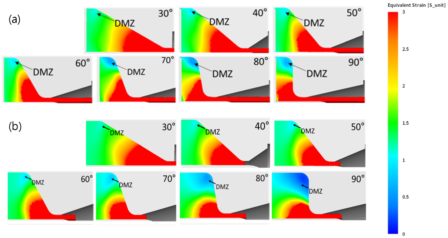
The effect of the corner radius at the exit and land length on extrusion load was negligible compared to the effect of corner radius at the entrance and die angle. The die angles of 50 and 60° are suitable for reducing extrusion load and ensuring stable plastic flow without a dead metal zone.
(2)
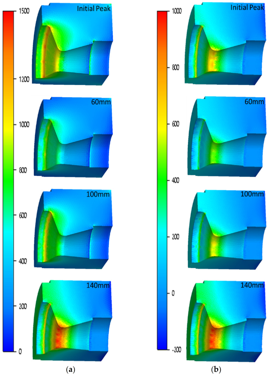
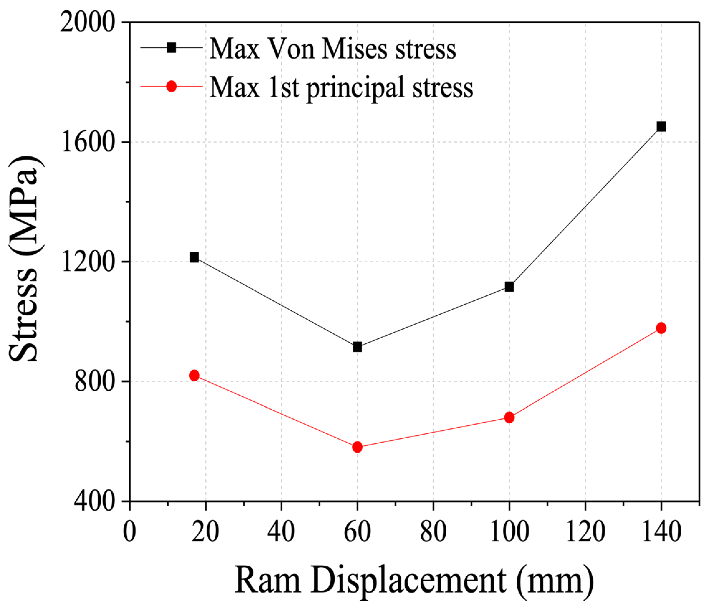
The von Mises stress of the extrusion die was higher at the corner of the die entrance at the early stage of the extrusion, although the position was changed to the corner of the die entrance at the later stage of the extrusion, while the first principal stress was the maximum at the corner of the die exit during the entire extrusion process.
(3)
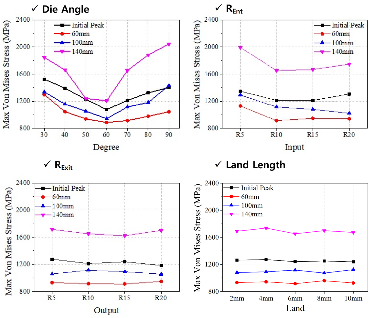
The effect of corner radius at the exit and land length on the maximum von Mises stress of the die was not severe compared to that of the other parameters similar to the case of extrusion load. The effect of die angle was dominant, and the maximum von Mises stress of the die was the minimum at the die angle of 60° for all displacements. The corner radius at the die entrance from 10 to 15 mm was recommendable for the current design.
(4)
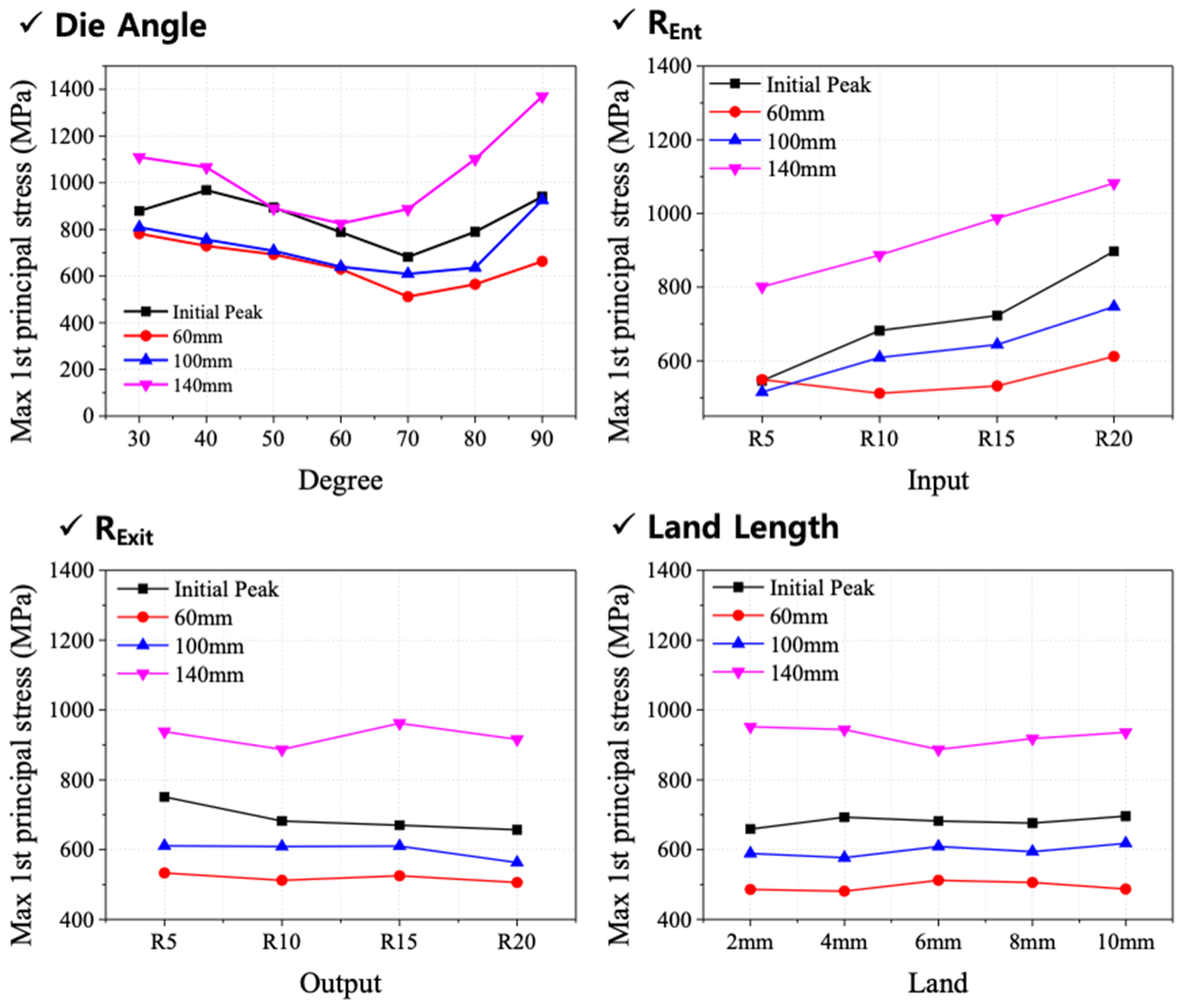
The effect of corner radius at the exit and land length was not notable. The die angles of 60 and 70° and a small corner radius at the entrance are suitable for the current design. In summary, the die angle of 60° and the corner radius at the die entrance between 10 and 15 mm form the optimal design for the current study from the viewpoint of extrusion load, metal flow, and die stress.

Author Contributions

Conceptualization, B.-J.C. and H.W.L.; Funding acquisition, S.-H.K. and H.W.L.; Methodology, B.-J.C., I.Y.M., Y.-S.O., J.J., J.-H.K., D.-K.K. and H.W.L.; Project administration, B.-J.C., S.-H.K. and H.W.L.; Software, B.-J.C., I.Y.M., Y.-S.O., S.-H.K. and S.-J.K.; Supervision, S.-H.K., J.-H.K., D.-K.K. and H.W.L.; Validation, I.Y.M., Y.-S.O., S.-H.K., S.-J.K., J.J., J.-H.K., D.-K.K. and H.W.L.; Visualization, B.-J.C., Y.-S.O., S.-J.K., J.J., J.-H.K. and D.-K.K.; Writing—original draft, B.-J.C., I.Y.M. and H.W.L.; Writing—review and editing, Y.-S.O., S.-H.K., S.-J.K., J.J., J.-H.K., D.-K.K. and H.W.L. All authors have read and agreed to the published version of the manuscript.

Funding

This work was supported by the Technology Innovation Program (N0002598 and N10063269) funded by the Ministry of Trade, Industry & Energy (MOTIE, Korea) and the fundamental research program of Korea Institute of Materials Science (PNK7760).

Institutional Review Board Statement

Not applicable.

Informed Consent Statement

Not applicable.

Data Availability Statement

The data presented in this study are available on request from the corresponding author. The data are not publicly available due to the Korea Institute of Materials Science (KIMS) data management regulations.

Conflicts of Interest

The authors declare no conflict of interest.

References

  1. Li, F.; Wang, Y.; Luo, Y.; Yan, X. Evaluation on the hot workability of as-extruded TA2 pure titanium using processing map. Adv. Mech. Eng. 2016, 8, 1687814016643888. [Google Scholar] [CrossRef] [Green Version]
  2. Chen, F.-J.; Yao, C.; Yang, Z.-G. Failure analysis on abnormal wall thinning of heat-transfer titanium tubes of condensers in nuclear power plant Part II: Erosion and cavitation corrosion. Eng. Fail. Anal. 2014, 37, 42–52. [Google Scholar] [CrossRef]
  3. Zhou, W.; Yu, J.; Lin, J.; Dean, T.A. Manufacturing a curved profile with fine grains and high strength by differential velocity sideways extrusion. Int. J. Mach. Tools Manuf. 2019, 140, 77–88. [Google Scholar] [CrossRef]
  4. Xue, Z.; Han, X.; Zhou, Z.; Wang, Y.; Li, X.; Wu, J. Effects of Microstructure and Texture Evolution on Strength Improvement of an Extruded Mg-10Gd-2Y-0.5Zn-0.3Zr Alloy. Metals 2018, 8, 1087. [Google Scholar] [CrossRef] [Green Version]
  5. Hsu, Q.-C.; Do, A.T. Formation ability welding seams and mechanical properties of high strength alloy AA7075 when extrusion hollow square tube. Int. J. Precis. Eng. Manuf. 2015, 16, 557–566. [Google Scholar] [CrossRef]
  6. Marín, M.M.; Camacho, A.M.; Pérez, J.A. Influence of the temperature on AA6061 aluminum alloy in a hot extrusion process. Procedia Manuf. 2017, 13, 327–334. [Google Scholar] [CrossRef]
  7. Tang, D.; Fang, W.; Fan, X.; Zou, T.; Li, Z.; Wang, H.; Li, D.; Peng, Y.; Wu, P. Evolution of the Material Microstructures and Mechanical Properties of AA1100 Aluminum Alloy within a Complex Porthole Die during Extrusion. Materials 2018, 12, 16. [Google Scholar] [CrossRef] [Green Version]
  8. Xue, X.; Vincze, G.; Pereira, A.; Pan, J.; Liao, J. Assessment of Metal Flow Balance in Multi-Output Porthole Hot Extrusion of AA6060 Thin-Walled Profile. Metals 2018, 8, 462. [Google Scholar] [CrossRef] [Green Version]
  9. Preedawiphat, P.; Mahayotsanun, N.; Sucharitpwatskul, S.; Funazuka, T.; Takatsuji, N.; Bureerat, S.; Dohda, K. Finite Element Analysis of Grain Size Effects on Curvature in Micro-Extrusion. Appl. Sci. 2020, 10, 4767. [Google Scholar] [CrossRef]
  10. Truong, T.-T.; Hsu, Q.-C.; Tong, V.-C.; Sheu, J.-J. A Design Approach of Porthole Die for Flow Balance in Extrusion of Complex Solid Aluminum Heatsink Profile with Large Variable Wall Thickness. Metals 2020, 10, 553. [Google Scholar] [CrossRef]
  11. Lee, I.-K.; Lee, S.-Y.; Lee, S.-K.; Jeong, M.-S.; Kim, D.H.; Lee, J.-W.; Cho, Y.-J. Porthole extrusion process design for magnesium alloy bumper back beam. Int. J. Precis. Eng. Manuf. 2015, 16, 1423–1428. [Google Scholar] [CrossRef]
  12. Yoon, D.; Kim, E.-Z.; Na, K.; Lee, Y.-S. A Study on the Forming Characteristics of AZ 31B Mg Alloy in a Combined Forward–Backward Extrusion at Warm Temperatures. Appl. Sci. 2018, 8, 2187. [Google Scholar] [CrossRef] [Green Version]
  13. Hansson, S.; Jansson, T. Sensitivity analysis of a finite element model for the simulation of stainless steel tube extrusion. J. Mater. Process. Technol. 2010, 210, 1386–1396. [Google Scholar] [CrossRef]
  14. Li, D.; He, Y.; Lianggang, G.; Lei, S.; Jun, Z.; Wenda, Z. Microstructure Responses to Key Extrusion Parameters of Large-Scale Thick-Walled 304 Stainless Steel Pipes Extrusion. Rare Met. Mater. Eng. 2014, 43, 2675–2681. [Google Scholar] [CrossRef]
  15. Udagawa, T.; Kropp, E.; Altan, T. Investigation of metal flow and temperatures by FEM in the extrusion of Ti-6Al-4V tubes. J. Mater. Process. Technol. 1992, 33, 155–174. [Google Scholar] [CrossRef]
  16. Srinivasan, K.; Venugopal, P. Influence of Die Angle on Containerless Extrusion of Commercially Pure Titanium Tubes. Mater. Manuf. Process. 2007, 22, 238–242. [Google Scholar] [CrossRef]
  17. Flitta, I.; Sheppard, T. Nature of friction in extrusion process and its effect on material flow. Mater. Sci. Technol. 2003, 19, 837–846. [Google Scholar] [CrossRef] [Green Version]
  18. Gattmah, J.; Ozturk, F.; Orhan, S. Effects of Process Parameters on Hot Extrusion of Hollow Tube. Arab. J. Sci. Eng. 2017, 42, 2021–2030. [Google Scholar] [CrossRef]
  19. Guo, L.-g.; Dong, K.-k.; Zhang, B.-j.; Yang, H.; Zheng, W.-d.; Liu, X.-w. Dynamic recrystallization rules in needle piercing extrusion for AISI304 stainless steel pipe. Trans. Nonferrous Met. Soc. China 2012, 22, s519–s527. [Google Scholar] [CrossRef]
  20. Li, L.X.; Rao, K.P.; Lou, Y.; Peng, D.S. A study on hot extrusion of Ti–6Al–4V using simulations and experiments. Int. J. Mech. Sci. 2002, 44, 2415–2425. [Google Scholar] [CrossRef]
  21. Mirahmadi, S.J.; Hamedi, M. Numerical and experimental investigation of process parameters in non-isothermal forward extrusion of Ti–6Al–4V. Int. J. Adv. Manuf. Technol. 2014, 75, 33–44. [Google Scholar] [CrossRef]
  22. Shin, T.J.; Lee, Y.H.; Yeom, J.T.; Chung, S.H.; Hong, S.S.; Shim, I.O.; Park, N.K.; Lee, C.S.; Hwang, S.M. Process optimal design in non-isothermal backward extrusion of a titanium alloy by the finite element method. Comput. Methods Appl. Mech. Eng. 2005, 194, 3838–3869. [Google Scholar] [CrossRef]
  23. Viswanath Ammu, V.N.S.U.; Mahendiran, P.; Agnihotri, A.; Ambade, S.; Dungore, P.R. A simplified approach for generation of bearing curve by velocity distribution and press validation for aluminum extruded profile. Int. J. Adv. Manuf. Technol. 2018, 98, 1733–1744. [Google Scholar] [CrossRef]
  24. Zhou, W.; Yu, J.; Lin, J.; Dean, T.A. Effects of die land length and geometry on curvature and effective strain of profiles produced by a novel sideways extrusion process. J. Mater. Process. Technol. 2020, 282, 116682. [Google Scholar] [CrossRef]
  25. Laue, K.; Stenger, H. Extrusion: Processes, Machinery, Tooling; American Society for Metals: Geauga County, OH, USA, 1981; p. 457. [Google Scholar]
  26. Damodaran, D.; Shivpuri, R. Prediction and control of part distortion during the hot extrusion of titanium alloys. J. Mater. Process. Technol. 2004, 150, 70–75. [Google Scholar] [CrossRef]
Figure 1. The geometry of the conventional extrusion dies used in the experiments.
Metals 11 01338 g001
Figure 2. The finite element meshes used in the current study.
Metals 11 01338 g002
Figure 3. Flow stress was used in finite element analysis, which was acquired by hot compression tests with strain rates of (a) 0.2, (b) 2 and (c) 20 s−1.
Metals 11 01338 g003
Figure 4. Comparison of load–displacement curves acquired by FE analysis in experiments.
Metals 11 01338 g004
Figure 5. Changes of load–displacement curves concerning design parameters of die shape.
Metals 11 01338 g005
Figure 6. Contour plots of strains with different die angles at the (a) initial peak and (b) end of the extrusion.
Metals 11 01338 g006
Figure 7. Changes in maximum stresses in the extrusion die concerning ram displacement.
Metals 11 01338 g007
Figure 8. Contour plots of the die stress concerning ram displacement: (a) von Mises and (b) first principal stresses.
Metals 11 01338 g008
Figure 9. Changes in the maximum von Mises stresses with different ram displacements and die shapes.
Metals 11 01338 g009
Figure 10. Changes in the maximum first principal stresses with different ram displacements and die shapes.
Metals 11 01338 g010
Table 1. The material properties of billet and tools used in the simulations.
MaterialConditionValue
Tools (H13)Specific heat 450   J / kg · K
Conductivity 29   W / m · K
Density7740 g / mm 3
Emissivity0.88
BilletSpecific heat 525   J / kg · K
Conductivity 7   W / m · K
Density4700 g / mm 3
Emissivity0.88
Table 2. The design parameters of the extrusion die used for numerical analysis.
AngleIn ROut RLand
30°10106
40°10106
50°10106
60°10106
70°10106
80°10106
90°10106
70°5106
70°10106
70°15106
70°20106
70°1056
70°10106
70°10156
70°10206
70°10102
70°10104
70°10106
70°10108
70°101010
Publisher’s Note: MDPI stays neutral with regard to jurisdictional claims in published maps and institutional affiliations.

