
Ground Structures-Based Topology Optimization of a Morphing Wing Using a Metaheuristic Algorithm


 ,
,  , ,
, ,  and
and
Abstract
1. Introduction
2. Aircraft Wing Model
2.1. Aerodynamic Model
2.2. Aeroelasticity Analysis
2.3. Flutter Analysis
2.4. Divergence Analysis
2.5. Lift Effectiveness
2.6. Buckling Analyses
3. Numerical Experiment
3.1. The Proposed Multiobjective Ground Structure Topology Optimization Problem
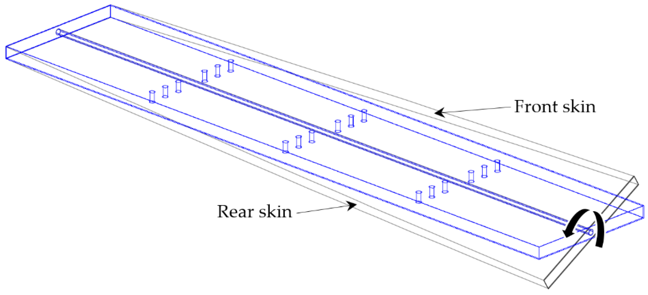
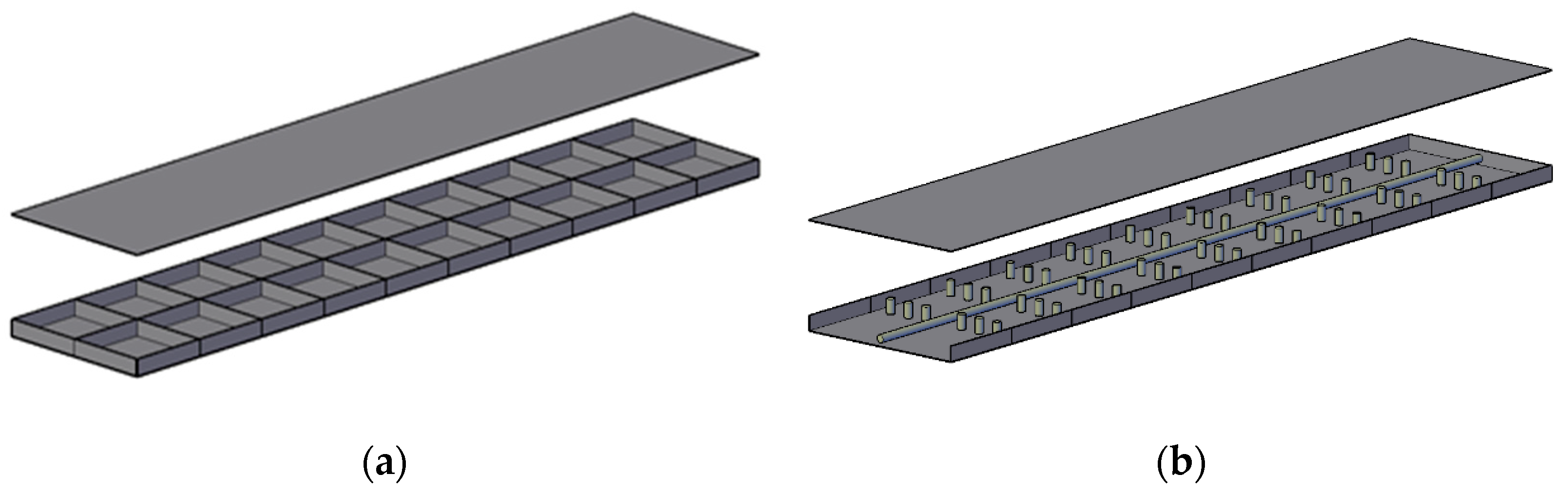
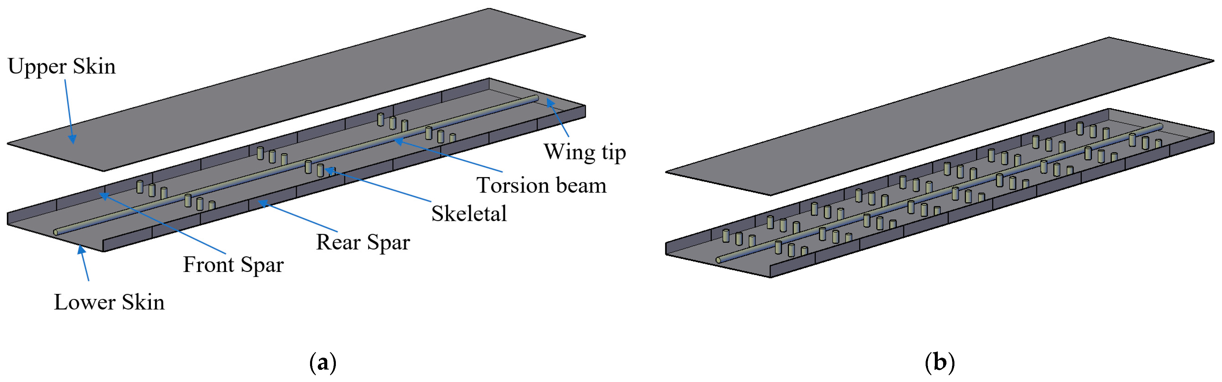
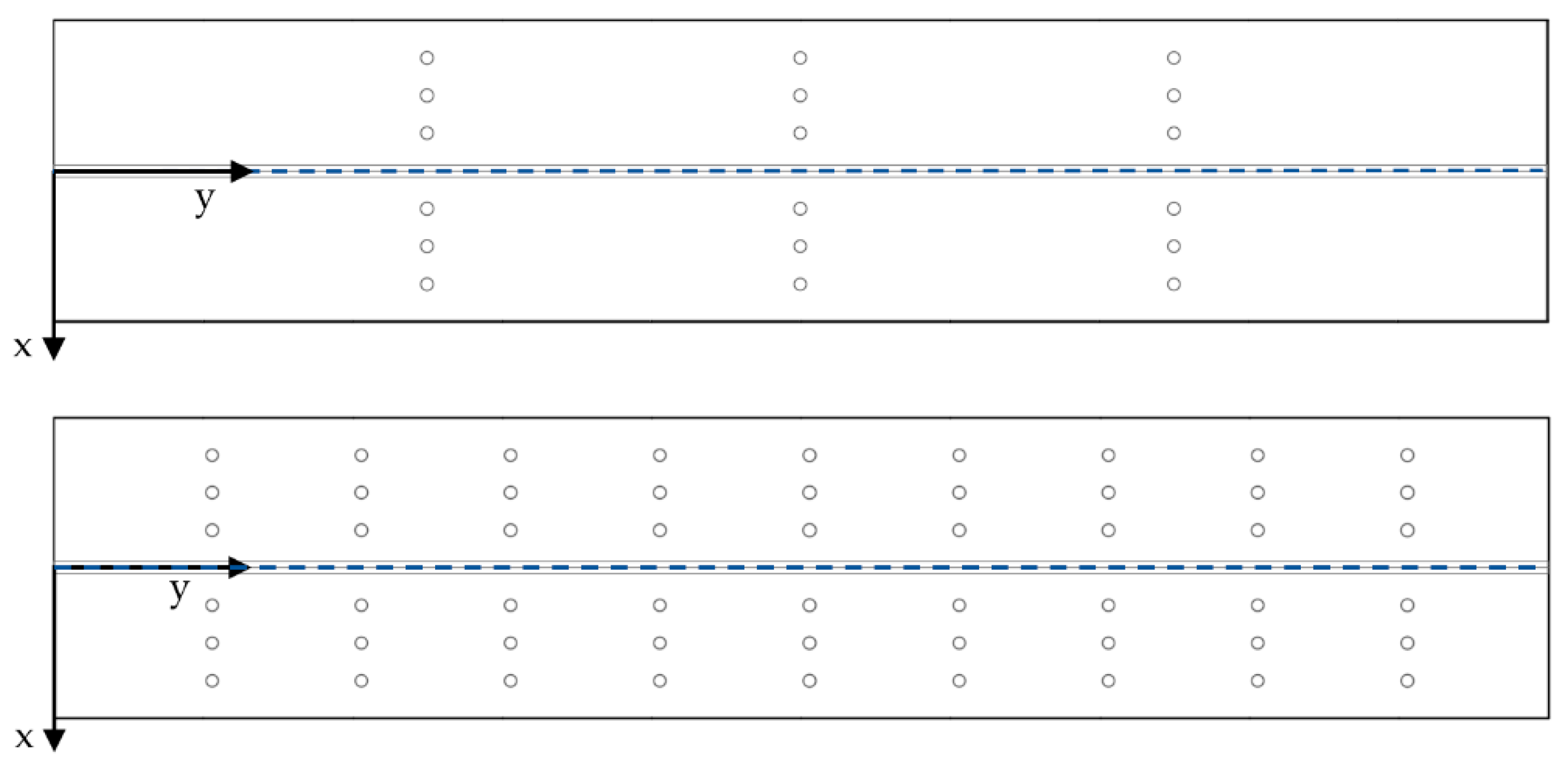
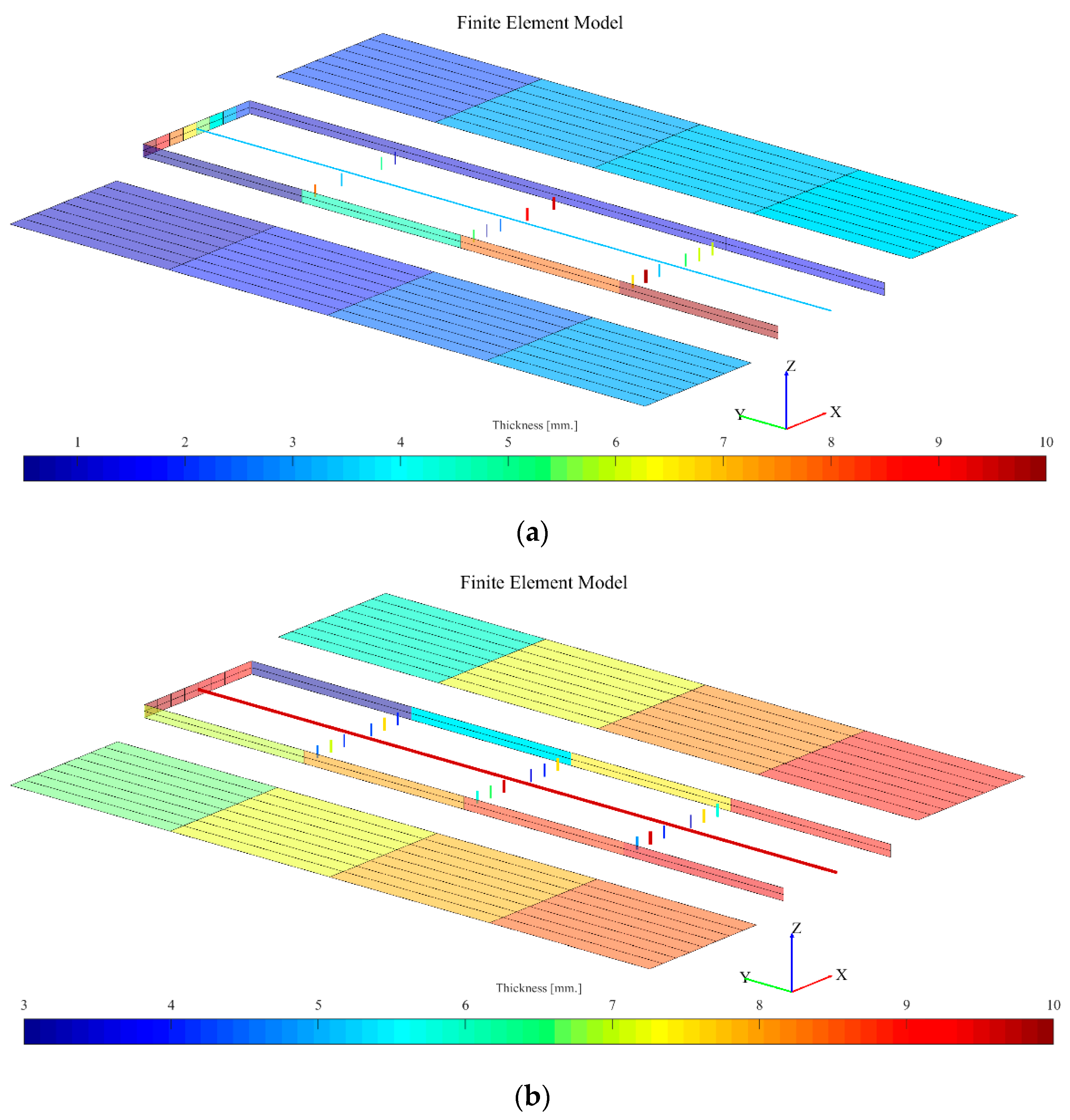
3.2. Numerical Simulation Model
4. Result and Discussion
5. Conclusions
Author Contributions
Funding
Institutional Review Board Statement
Informed Consent Statement
Data Availability Statement
Acknowledgments
Conflicts of Interest
References
- Sofla, A.; Meguid, S.; Tan, K.; Yeo, W.K. Design Shape morphing of aircraft wing: Status and challenges. J. Mater. Des. 2010, 31, 1284–1292. [Google Scholar] [CrossRef]
- Ajaj, R.M.; Parancheerivilakkathil, M.S.; Amoozgar, M.; Friswell, M.I.; Cantwell, W.J. Recent developments in the aeroelasticity of morphing aircraft. Prog. Aerosp. Sci. 2021, 120, 100682. [Google Scholar] [CrossRef]
- Barbarino, S.O.; Bilgen, R.M.; Ajaj, M.I.; Friswell, D.J. A review of morphing aircraft. J. Int. Mater. Syst. Struct. 2011, 22, 823–877. [Google Scholar] [CrossRef]
- Love, M.P.; Zink, P.; Wieselmann, P.; Youngren, H. Body freedom flutter of high aspect ratio flying wings. Struct. Struct. Dyn. Mater. Confer. 2005, 1947. [Google Scholar] [CrossRef]
- Ajaj, R.; Friswell, M.; Dettmer, W.; Isikveren, A.; Allegri, G. Conceptual modeling of an adaptive torsion wing structure. Struct. Confer. 2011, 13, 1883. [Google Scholar]
- Ajaj, R.; Friswell, M.; Dettmer, W.; Allegri, G.; Isikveren, A.T. Dynamic modelling and actuation of the adaptive torsion wing. J. Intell. Mater. Syst. Struct. 2013, 24, 2045–2057. [Google Scholar] [CrossRef]
- Wang, L.; Lui, G.; Qiu, Z. Review: Recent Developments in the Uncertainty-Based Aero-Structural Design Optimization for Aerospace Vehicles. J. Harbin Inst. Tech. 2018, 25, 1–15. [Google Scholar]
- Burdette, D.A.; Martins, J.R. Design of a transonic wing with an adaptive morphing trailing edge via aerostructural optimization. Aerosp. Sci. Technol. 2018, 81, 192–203. [Google Scholar] [CrossRef]
- Molinari, G.; Quack, M.; Arrieta, A.F.; Morari, M.; Ermanni, P. Realization and structural testing of a compliant adaptable wing. Smart Mater. Struct. 2015, 24, 105027. [Google Scholar] [CrossRef]
- Henry, C.; Molinari, G.; Rivas-Padilla, J.R.; Arrieta, A.F. Smart morphing wing: Optimization of distributed piezoelectric actuation. AIAA J. 2019, 57, 2384–2393. [Google Scholar] [CrossRef]
- Grihon, S.; Krog, L.; Tucker, A.; Hertel, K. A380 weight savings using numerical structural optimization. In Proceedings of the 20th AAAF Colloquium on Material for Aerospace Applications, Paris, France, 24–26 November 2004; pp. 763–766. [Google Scholar]
- Krog, L.; Tucker, A.; Kemp, M.; Boyd, R. Topology optimization of aircraft wing box ribs. In Proceedings of the 10th AIAA/ISSMO Multidisciplinary Analysis and Optimization Conference, New York, NY, USA, 30 August–1 September 2004. [Google Scholar]
- Saitou, K.; Izui, K.; Nishiwaki, S.; Papalambros, P. A survey of structural optimization in mechanical product development. Trans. ASME 2005, 5, 214–226. [Google Scholar] [CrossRef]
- Rothwell, A. Multi-level optimization of aircraft shell structures. Thin-Walled Struct. 1991, 11, 85–103. [Google Scholar] [CrossRef][Green Version]
- Lencus, A.; Querin, O.M.; Steven, G.P.; Xie, Y.M. Aircraft wing design automation with ESO and GESO. Int. J. Veh. Des. 2001, 28, 98–111. [Google Scholar] [CrossRef]
- Harzen, L.U.; Peter, H. Multilevel optimization in aircraft structural design evaluation. Comput. Struct. 2008, 86, 104–118. [Google Scholar]
- Sleesongsom, S.; Bureerat, S. New conceptual design of aeroelastic wing structures by multiobjective optimization. Eng. Optim. 2013, 45, 107–122. [Google Scholar] [CrossRef]
- Bendsøe, M.; Sigmund, O. Topology Optimization; Springer: Berlin/Heidelberg, Germany, 2003. [Google Scholar]
- Saggere, L.; Kota, S. Static shape control of smart structures using compliant mechanisms. AIAA J. 1999, 37, 572–578. [Google Scholar] [CrossRef]
- Sleesongsom, S.; Bureerat, S. Aircraft morphing wing design by using partial topology optimization. Struct. Multidiscip. Optim. 2013, 48, 1109–1128. [Google Scholar] [CrossRef]
- Sleesongsom, S.; Bureerat, S. Morphing Wing Structural Optimization Using Opposite-Based Population-Based Incremental Learning and Multigrid Ground Elements. Mathemat. Probl. Eng. 2015, 2015, 730626. [Google Scholar] [CrossRef]
- Meng, L.; Zhang, W.; Quan, D.; Shi, G.; Tang, L.; Hou, Y.; Breitkopf, P.; Zhu, J.; Gao, T. From topology optimization design to additive manufacturing: Today’s success and tomorrow’s roadmap. Arch. Comput. Methods Eng. 2020, 27, 805–830. [Google Scholar] [CrossRef]
- Stanford, B.; Dunning, P.D. Optimal Topology of Aircraft Rib and Spar Structures under Aeroelastic Loads. J. Aircr. 2015, 52, 1298–1311. [Google Scholar] [CrossRef]
- Stanford, B. Aeroelastic Wing box stiffener topology optimization. J. Aircr. 2018, 55, 1244–1251. [Google Scholar] [CrossRef]
- Stanford, B.; Beran, B.; Bhatia, M. Aeroelastic Topology Optimization of Blade-Stiffened Panels. J. Aircr. 2014, 51, 938–944. [Google Scholar] [CrossRef]
- Maute, K.; Allen, M. Conceptual design of aeroelastic structures by topology optimization. Struct. Multidiscip. Optim. 2004, 27, 27–42. [Google Scholar] [CrossRef]
- Towsend, S.; Kim, H. A level set topology optimization method for the buckling of shell structures. Struct. Multidiscip. Optim. 2019, 60, 1783–1800. [Google Scholar] [CrossRef]
- Yang, W.; Yue, Z.; Li, L.; Wang, P. Aircraft wing structural design optimization based on automated finite element modelling and ground structure approach. Eng. Optim. 2016, 48, 94–114. [Google Scholar] [CrossRef]
- Fasel, U.; Keidel, D.; Baumann, L.; Cavolina, G.; Eichenhofer, M.; Ermanni, P. Composite additive manufacturing of morphing aerospace structures. Manuf. Lett. 2020, 23, 85–88. [Google Scholar] [CrossRef]
- Song, L.; Gao, T.; Tang, L.; Du, X.; Zhu, J.; Lin, Y.; Shi, G.; Liu, H.; Zhou, G.; Zhang, W. An all-movable rudder designed by thermo-elastic topology optimization and manufactured by additive manufacturing. Comput. Struct. 2021, 243, 106405. [Google Scholar] [CrossRef]
- Sleesongsom, S.; Yooyen, S.; Prapamonthon, P.; Bureerat, S. Reliability-based Design Optimization of Classical Wing Aeroelasticity. IOP Conf. Ser. Mater. Sci. Eng. 2020, 886, 012015. [Google Scholar] [CrossRef]
- Wansaseub, K.; Sleesongsom, S.; Panagant, N.; Pholdee, N.; Bureerat, S. Surrogate-Assisted Reliability Optimisation of an Aircraft Wing with Static and Dynamic Aeroelastic Constraints. Int. J. Aeronaut. Space 2020, 21, 723–732. [Google Scholar] [CrossRef]
- Winyangkul, S.; Sleesongsom, S.; Bureerat, S. Reliability-Based Design of an Aircraft Wing Using a Fuzzy-Based Metaheuristic. Appl. Sci. 2021, 11, 6463. [Google Scholar] [CrossRef]
- Wansasueb, K.; Pholdee, N.; Panagant, N.; Bureerat, S. Multiobjective meta-heuristic with iterative parameter distribution estimation for aeroelastic design of an aircraft wing. J. Eng. Comput. 2020, 45, 1–19. [Google Scholar] [CrossRef]
- Guo, S.; Li, D.; Liu, Y. Multi-objective optimization of a composite wing subject to strength and aeroelastic constraints. Part G J. Aerosp. Eng. 2012, 226, 1095–1106. [Google Scholar] [CrossRef]


| Properties | Value | Unit |
|---|---|---|
| Young’s modulus (E) | 70 × 109 | Pa |
| Poisson’s ratio (ν) | 0.3 | - |
| Density (ρ) | 2700 | kg/m3 |
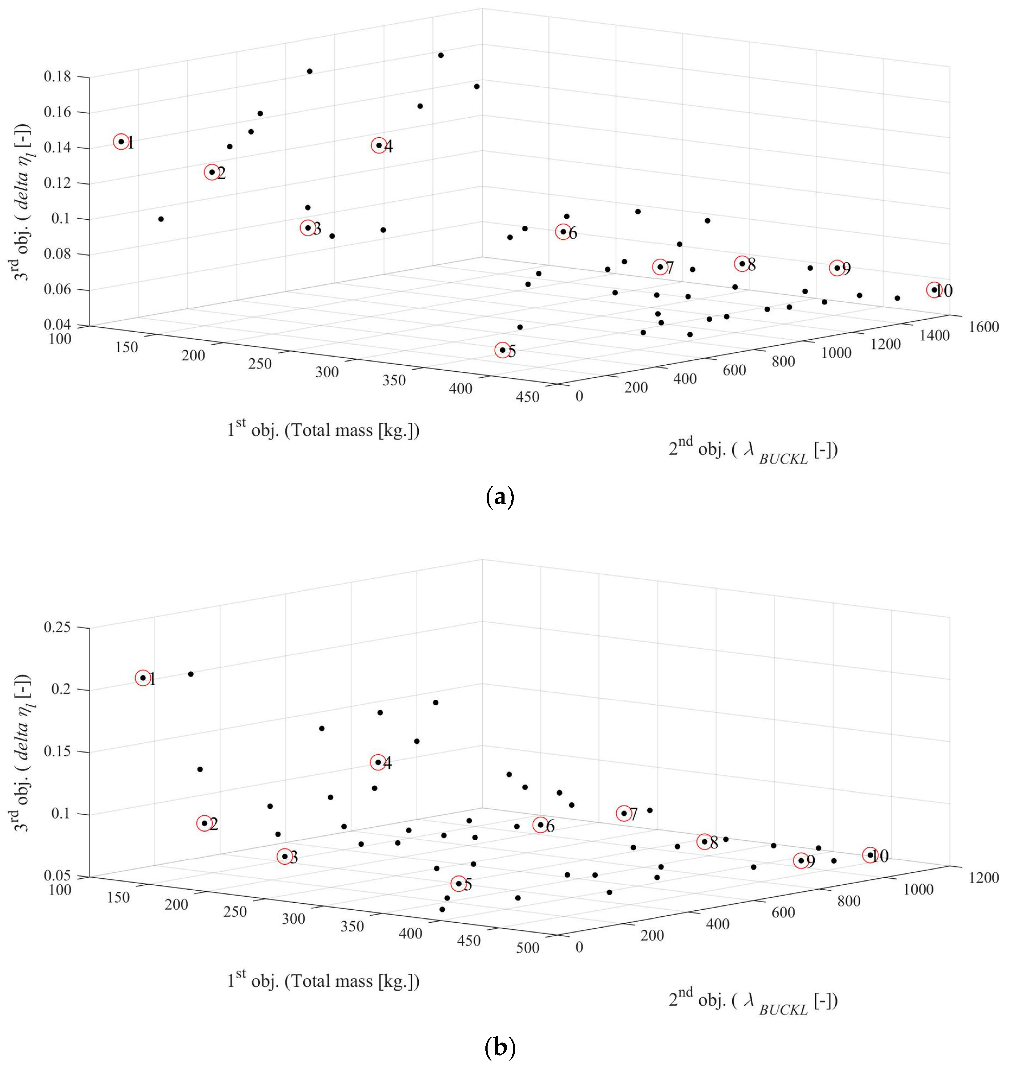
| Pareto Front No. | Total Mass [kg.] | 1st Buckling [Hz] | Critical Speed [m/s] | Lift Effectiveness [-] | Maximum Transverse Displacement [m.] |
|---|---|---|---|---|---|
| 1 | 115.3216 | 38.895 | 132.551 | 1.0514 | 0.014869 |
| 2 | 121.2212 | 153.3221 | 133.3737 | 1.0783 | 0.014738 |
| 3 | 133.7867 | 256.918 | 137.2478 | 1.1049 | 0.012281 |
| 4 | 147.6443 | 447.1008 | 143.5185 | 1.0738 | 0.0098151 |
| 5 | 235.8701 | 708.6025 | 180.0119 | 1.1208 | 0.0069166 |
| 6 | 296.3996 | 923.7469 | 205.794 | 1.1257 | 0.0053827 |
| 7 | 298.355 | 930.8718 | 201.5853 | 1.1323 | 0.0051402 |
| 8 | 368.1159 | 932.1128 | 218.7638 | 1.1359 | 0.0047649 |
| 9 | 397.7724 | 986.4532 | 224.1757 | 1.1448 | 0.0043251 |
| 10 | 411.625 | 1133.1864 | 219.5524 | 1.1451 | 0.0032751 |
| Pareto Front No. | Total Mass [kg.] | 1st Buckling [Hz] | Critical Speed [m/s] | Lift Effectiveness [-] | Maximum Transverse Displacement [m.] |
|---|---|---|---|---|---|
| 1 | 125.0137 | 358.1264 | 51.8779 | 1.0834 | 0.013977 |
| 2 | 182.0729 | 630.0362 | 84.9946 | 1.1027 | 0.0094806 |
| 3 | 186.5354 | 651.6634 | 86.7379 | 1.1084 | 0.0090102 |
| 4 | 243.907 | 866.4353 | 129.7583 | 1.1275 | 0.0068166 |
| 5 | 277.4928 | 1136.3719 | 114.6718 | 1.1289 | 0.0064867 |
| 6 | 288.6587 | 1280.4411 | 119.4554 | 1.1323 | 0.0062072 |
| 7 | 345.9147 | 1376.5109 | 133.3505 | 1.1452 | 0.004934 |
| 8 | 355.1918 | 1421.8814 | 130.8912 | 1.1538 | 0.005063 |
| 9 | 422.4793 | 1725.0638 | 139.6456 | 1.1537 | 0.0044053 |
| 10 | 440.5869 | 1844.4355 | 142.4508 | 1.1639 | 0.0043311 |
Shape Changing | Lift Effectiveness | Torque (N-m) |
|---|---|---|
 | 1.1957 | +1000 |
 | 1.1744 | +800 |
 | 1.1532 | +600 |
 | 1.1319 | +400 |
 | 1.1107 | +200 |
 | 1.0894 | 0 |
 | 1.0682 | −200 |
 | 1.0470 | −400 |
 | 1.0257 | −600 |
 | 1.0045 | −800 |
 | 0.98322 | −1000 |
Publisher’s Note: MDPI stays neutral with regard to jurisdictional claims in published maps and institutional affiliations. |
© 2021 by the authors. Licensee MDPI, Basel, Switzerland. This article is an open access article distributed under the terms and conditions of the Creative Commons Attribution (CC BY) license (https://creativecommons.org/licenses/by/4.0/).
Share and Cite
Winyangkul, S.; Wansaseub, K.; Sleesongsom, S.; Panagant, N.; Kumar, S.; Bureerat, S.; Pholdee, N. Ground Structures-Based Topology Optimization of a Morphing Wing Using a Metaheuristic Algorithm. Metals 2021, 11, 1311. https://doi.org/10.3390/met11081311
Winyangkul S, Wansaseub K, Sleesongsom S, Panagant N, Kumar S, Bureerat S, Pholdee N. Ground Structures-Based Topology Optimization of a Morphing Wing Using a Metaheuristic Algorithm. Metals. 2021; 11(8):1311. https://doi.org/10.3390/met11081311
Chicago/Turabian StyleWinyangkul, Seksan, Kittinan Wansaseub, Suwin Sleesongsom, Natee Panagant, Sumit Kumar, Sujin Bureerat, and Nantiwat Pholdee. 2021. "Ground Structures-Based Topology Optimization of a Morphing Wing Using a Metaheuristic Algorithm" Metals 11, no. 8: 1311. https://doi.org/10.3390/met11081311
APA StyleWinyangkul, S., Wansaseub, K., Sleesongsom, S., Panagant, N., Kumar, S., Bureerat, S., & Pholdee, N. (2021). Ground Structures-Based Topology Optimization of a Morphing Wing Using a Metaheuristic Algorithm. Metals, 11(8), 1311. https://doi.org/10.3390/met11081311