Article

Compressive Properties and Failure Mechanisms of Gradient Aluminum Foams Prepared by a Powder Metallurgy Method

1
School of Material Science and Technology, Taiyuan University of Science and Technology, Taiyuan 030024, China
2
School of Material Science and Technology, North University of China, Taiyuan 030051, China
*
Author to whom correspondence should be addressed.
Metals 2021, 11(9), 1337; https://doi.org/10.3390/met11091337
Submission received: 14 July 2021 / Revised: 16 August 2021 / Accepted: 20 August 2021 / Published: 24 August 2021

Abstract

:
A layered gradient aluminum foam was prepared by powder sintering with sodium thiosulfate (Na2S2O3) particles as the cell-forming agent. By cutting, polishing and observing under a microscope, it was found that the aluminum powder particles were not completely melted after sintering but were only combined by surface melting. Based on the quasi-static compression test and the macroscopic diagram of the sample during deformation, the mechanical properties of gradient aluminum foam were studied, and their deformation characteristics and mechanism were analyzed and discussed.

1. Introduction

Foamed metallic materials (FMM) are materials that have a foam structure and contain a large of number of cells in the base metal materials. Owing to the abundant cells, foamed metallic materials possess unique functional properties, such as light weight, damping, energy absorption, heat dissipation, colation, etc., therefore drawing significant attention from the industrial field [1,2,3,4,5,6,7,8]. In particular, Al and Al alloys are typically used for foamed metallic materials due to their excellent castability and industrial significance [6]. Extensive studies have been conducted to investigate the mechanical property, energy absorption capability and damping property of uniform Al foams [9,10,11,12,13,14,15,16,17,18]. To optimize the functional properties of foams, functionally graded foams have been widely studied for higher performance and effectiveness [4,6,19,20,21,22,23] instead of uniform foam. The graded foams consist of a gradual change in their property from one location to another.
Introducing a gradient to foam materials may alter deformation modes and result in various mechanical properties. Many methods for preparing uniform metal foams can be used to prepare metal foams with a gradient structure. According to the cell structure, gradient metal foams can be divided into open-cell structure metal foams [22,23], metal matrix syntactic foams [6,24,25] and closed-cell structure metal foams [20,21,26,27,28]. At present, a gradient is usually introduced to foam materials by changing the relative density distribution. Therefore, the relative density of the gradient foam is not uniform. Cell size and cell-wall thickness are two important parameters to adjust the relative density of foam materials. Some researchers have changed the cell size distribution and cell-wall thickness gradients to study the gradient effect on the mechanical properties of foams [21,22,23,26,27,28,29]. Changes in cell size and cell-wall thickness are mainly used to study the effect of density gradient of foam materials on performance. Meanwhile, functionally graded Al foams with both open-cell structures and closed-cell structures have also been prepared and researched. However, there have been few studies on size gradient aluminum foams with open-cell structures and uniform relative densities. Al foams with open-cell structures have good filtration characteristics and heat-release properties. Therefore, cell-size gradient Al foams with open-cell structures and uniform relative densities are worth to study.
In this study, two-layered cell-size gradient Al foams (SGAF) with open-cell structures and uniform porosity were prepared by the sintering dissolution method. Urea [30,31] and salt (NaCl) [32] have often been selected as a spacer to prepare Al foam for a space holder. However, these spacers have weak corrosion, which will corrode the Al base and reduce the mechanical properties of Al foam. Moreover, the residual urea in the sintering process will decompose to produce ammonia gas, which pollutes the environment. Sodium thiosulfate (Na2S2O3) was selected as the spacer in this study. Its solution is non-toxic, soluble in water and easily removed from aluminum foam. Meanwhile its solution is neutral, which produces no corrosion on aluminum metal and little environmental pollution. In this paper, the porosity of SGAF was fixed at 70%. The Al foams with cell-size gradients were produced. In this paper, the cell sizes of gradient Al foams include 4 mm, 3 mm, 2 mm, (i.e., 4-3, 4-2 and 3-2). 4-3, 4-2 and 3-2 refer to two-layered gradient Al foams with cell sizes of 4 mm and 3 mm, 4 mm and 2 mm, 3 mm and 2 mm, respectively. The effects of cell size on the quasi-static compressive behavior of SGAF have been investigated. After evaluation of the compressive properties, deformation and failure mechanisms were also discussed.

2. Experimental Procedure

2.1. Fabrication of Two-Layered Cell Size Gradient Al Foams (SGAF)

SGAF were prepared by the sintering dissolution process. Aluminum powders (technically pure 99.98%, 300 meshes) were used as base materials. Sodium thiosulfate (Na2S2O3) was chosen as the space support; the sizes included 4 mm, 3 mm and 2 mm. The cell size and porosity of SGAF were precisely controlled by adjusting the mass and size of sodium thiosulfate (Na2S2O3) and aluminum powders. The two powders needed to be mixed evenly. Before stirring, a small amount of alcohol was added. This operation was conducive to the better adhesion of aluminum powder to the surface of the space support to improve the uniformity of cell distribution. The mixture was poured into a cold press mold for 10 min under a pressure of 370 MPa. Then, a cold press block with a diameter of 40 mm and a height of 30 mm was obtained. Meanwhile, the cold press block was polished to remove the edges and burrs. The specimens were immersed in a constant temperature water bath at 60 °C for over 5 h to ensure that the space bracket was completely dissolved. After drying at 100 °C for 30 min, the foamed aluminum samples were sintered in a furnace at 620 °C for 5 h and then cooled to room temperature in the furnace. The size of the prepared aluminum foam sample was a cylinder with a diameter of 40 mm and a height of 30 mm, and the porosity was 70%. The diameter of the cells was the same as that of sodium thiosulfate, i.e., 4 mm, 3 mm and 2 mm.

2.2. Structure Characterization

The specimens were cut into a semicircle with a diameter of 40 mm by using an electric discharge machine (Longkai Technology Co., Ltd., Suzhou city, China). The specimen’s density was determined by its weight and physical dimensions, in which the porosity of the foam is defined as
P = 1     ρ   ρ s
where P is the porosity; ρ and ρs are the densities of the aluminum foam samples and the cell wall material, respectively.
For observing the microstructural features, the samples were polished with sandpaper and corroded with a 15% sodium hydroxide solution. Micrographs were taken under an optical microscope (Keyence (China) Co., Ltd., Shanghai, China), and then the samples were scanned under the printer LaserJet M1136 MFP (China Hewlett-Packard Co., Ltd., Beijing, China) with the resolution set at 1200 dpi to observe the macroscopic cells and microstructure.

2.3. Quasi-Static Compressive Test

Quasi-static compressive tests of the specimens were conducted at room temperature with a crosshead speed of 3 mm/min by an Electron Universal Material Testing Machine (UTM 5305 × 300 kN) (Suns Technology Co., Ltd., Shenzhen, China). Platform stress is the average pressure within the range of 10–45% strain. Stress drop, a parameter to describe cell-wall collapse when stress exceeds the yield stress and stress redistributes during compressive process, is defined as:
S = (Su − Sl)/Su
where S is stress drop rate, and Su is the high yield point stress. Sl the low yield point stress.

3. Results and Discussion

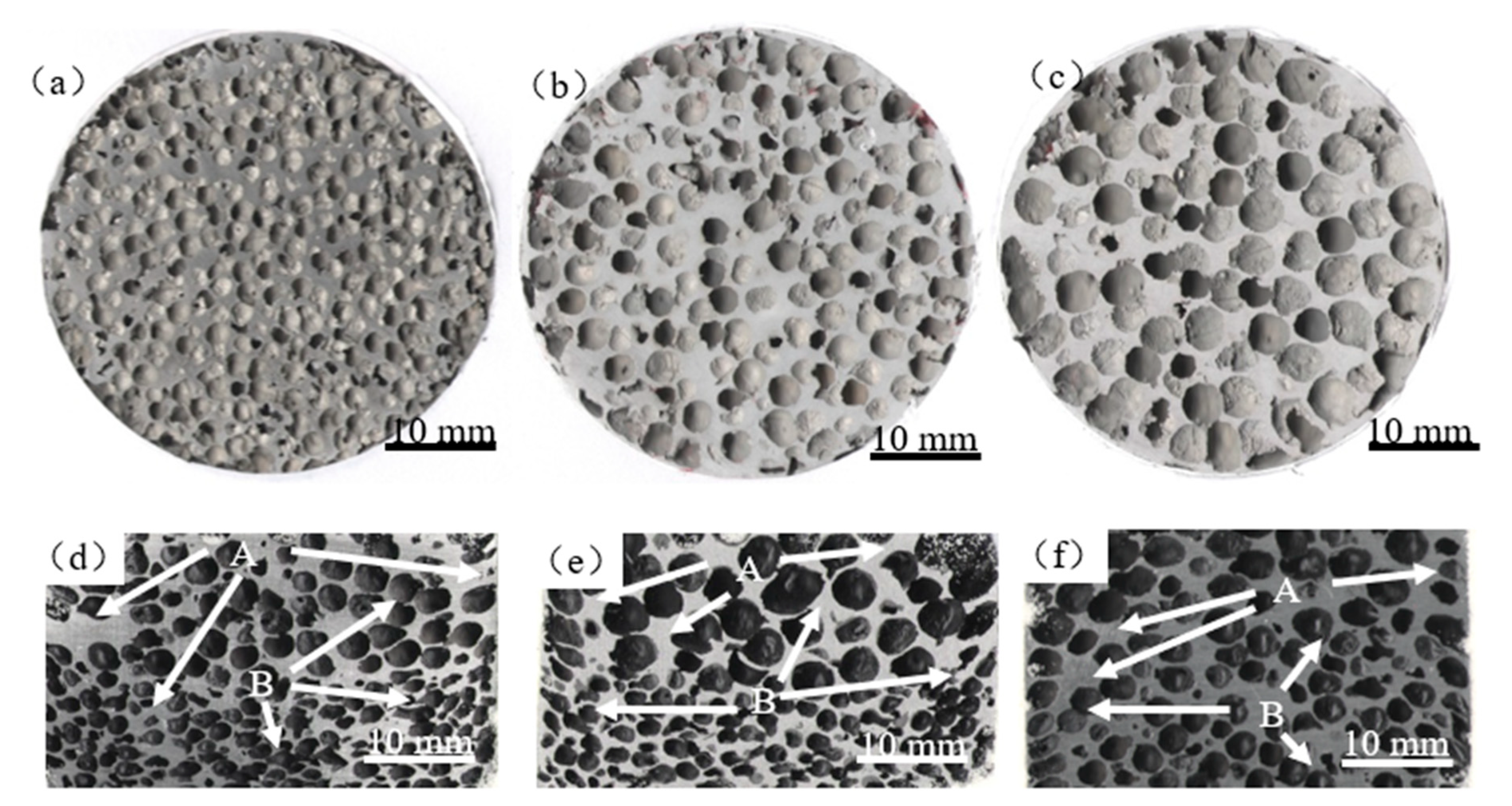
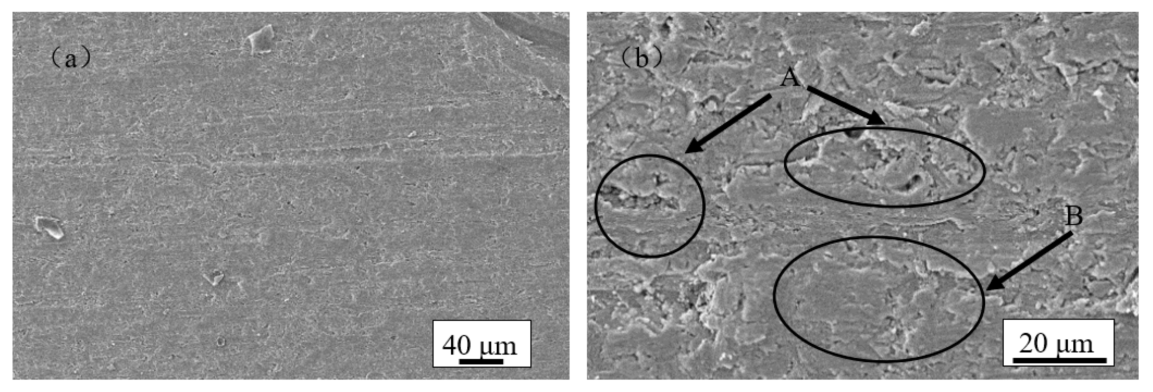
3.1. Morphology Observation

The cell structure of SGAF is shown in Figure 1. Figure 1a–c shows the transverse direction sectional views of the aluminum foam samples with cell size of 4 mm, 3 mm and 2 mm. The whole cell shape was round, similar to the shape of sodium thiosulfate particles. At the same time, with the increase of cell diameter, the thickness of the cell wall increased, which will have a certain impact on the mechanical properties of the material. Figure 1e–f showed the longitudinal direction sectional views of gradient aluminum foams with different cell size gradients (4-3, 4-2, 3-2). It can be seen that all the cells were deformed to some extent in the pressure direction, forming an elliptical shape and that the degree of deformation decreased with the increase of the cell size. The ellipse degree of the hole also had a certain influence on its mechanical properties. At the same time, it can be observed that the distribution of the aluminum matrix was not uniform, with obvious aggregation at A and weakness at B. This may have some influence on the deformation process. In addition, there was obvious connectivity between some cells. This was due to the deformation and friction of sodium thiosulfate particles during the compression process, which leads to the aggregation of aluminum powder. Meanwhile, it can be observed that the larger the cell size of the sample, the thicker the cell wall. The thickness of the cell wall has a great influence on the mechanical properties of the samples—thicker walls are stronger. With the same porosity, the thicker the cell wall, the higher the mechanical properties.
Figure 2 shows the microstructure of the cell wall of SGAF after polishing and corrosion under metallographic microscope. In Figure 2a,b, the boundary line between aluminum powder particles can be clearly observed at different scales. This proved that the aluminum powder particles were not completely melted during the preparation process. In Figure 2c,d, the boundary line between aluminum powder particles can be clearly observed at A. It indicated that the bond between aluminum powder particles was not very tight. When subjected to pressure, cracks are prone to occur at this place, leading to the fracture of the cell wall, and then the strength of aluminum foam decreases. However, the combination of particles at B was relatively good. This was caused by the fusion of the surface of some aluminum powder particles during sintering and adhesion to each other.
Figure 3 shows the microstructure of an aluminum foamed cell wall under a scanning electron microscope. In Figure 3a, it can be clearly observed that aluminum powder particles deformed significantly after being compacted and formed. Therefore, there were no obvious gaps between particles, making it easier for particles to combine in the sintering process. It can be observed from Figure 3b that there was an obvious gap between aluminum powder particles at A. This indicated that it was not sufficient to combine the melted aluminum powder particles in the sintering process. This may be due to the insufficient deformation of some aluminum powder particles in the deformation process, which does not fill up the gap. Thus, the result was insufficient melting and bonding between aluminum powder particles. The boundary at B was relatively good, and the boundary was bent and interlocked, which is beneficial to improving the bond strength.

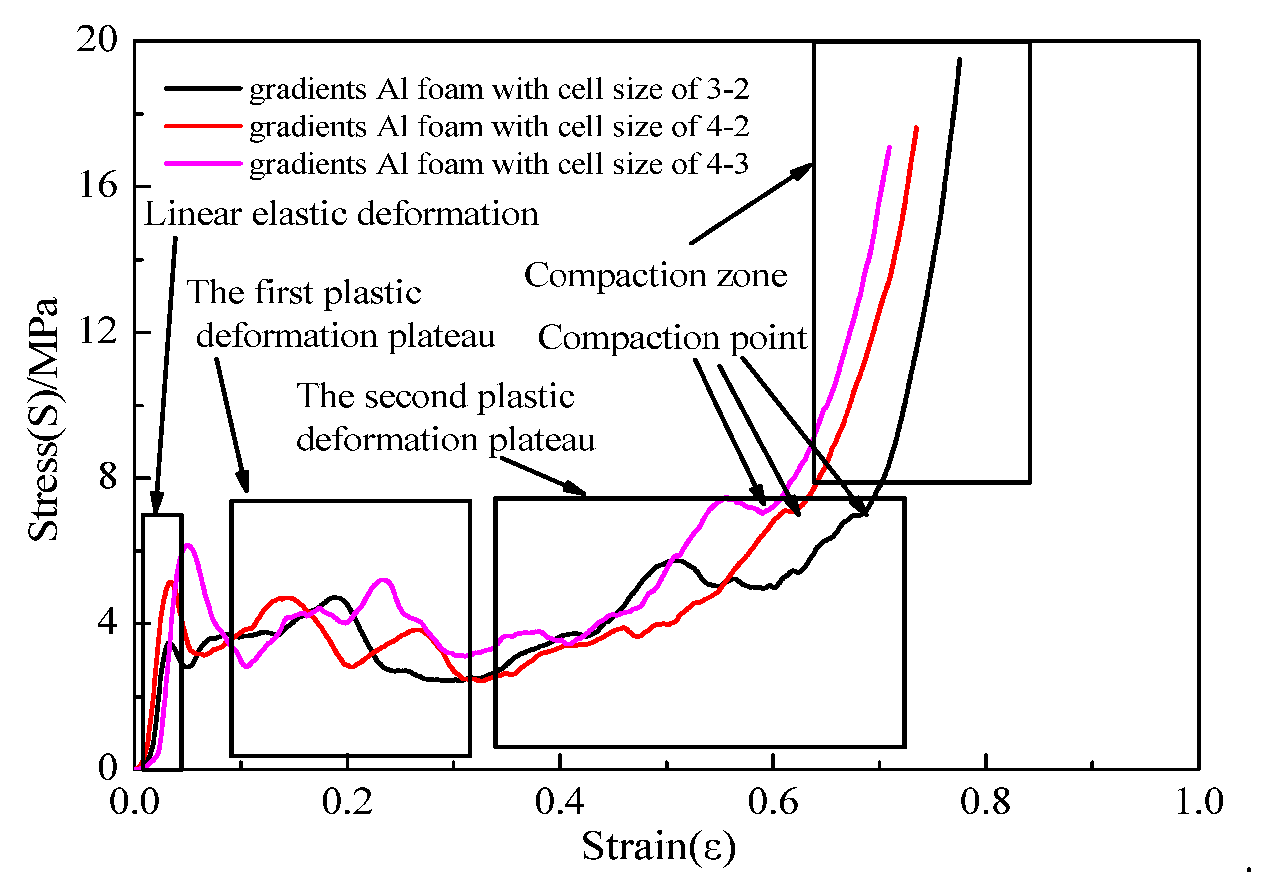
3.2. Effects of Two-Layered Structure of Samples on Mechanical Properties

Figure 4 shows the compressive curves of two-layered structure Al foams with different cell size gradients (4-3, 4-2, 3-2). It shows three obvious stages, namely, the linear elastic deformation zone, a long plateau of plastic deformation and the compaction zone. Two obvious deformation zones can be seen in the plateau area. These two deformation zones are closely related to the deformation of two layers of gradient Al foams with different cell sizes. In Figure 4, it can be observed that there was a large fluctuation in the plateau area. This was due to the partial melting and bonding between the aluminum powder particles, which is obviously different from the aluminum foam prepared by the melt foaming method. When the size of the sample was 4-3, 4-2, 3-2, the compaction strain increased gradually. This is because, with the same porosity, the smaller the cell diameter, the thinner the cell wall, and the cracked cell wall was easier to be compacted and deformed after the collapse, and there was more compaction space.
Table 1 shows the peak stress, plateau stress and stress drop ratio of the samples with different cell sizes during compression. It can be seen from Table 1 that, when the sample sizes were 4-3, 4-2, 3-2, the peak stress was 6.2 MPa, 5.2 MPa and 3.5 MPa respectively. The peak stress decreased by nearly 43.5% when the cell sizes of the samples changed from 4-3 to 3-2. This is because the larger the cell size was, the thicker the cell wall; thus, the harder it was to be damaged. Moreover, the corresponding plateau stresses were 3.9 MPa, 3.5 MPa and 3.5 MPa, respectively. It can be seen that the stress was relatively close in the process of collapse. The corresponding stress drop ratio was 55.2%, 40.4% and 20.3%, and the stress drop ratio decreased gradually. The stress drop ratio decreased by nearly 63.2% when the cell sizes of the samples changed from 4-3 to 3-2. This is because, with the decrease of the cell size in the samples, the collapse space of each layer of cells is relatively small in the failure process, and then the stress fluctuation caused by the collapse process is relatively small. Therefore, the yield stress and the stress fluctuation increase with the increase of the cell diameter of the sample.

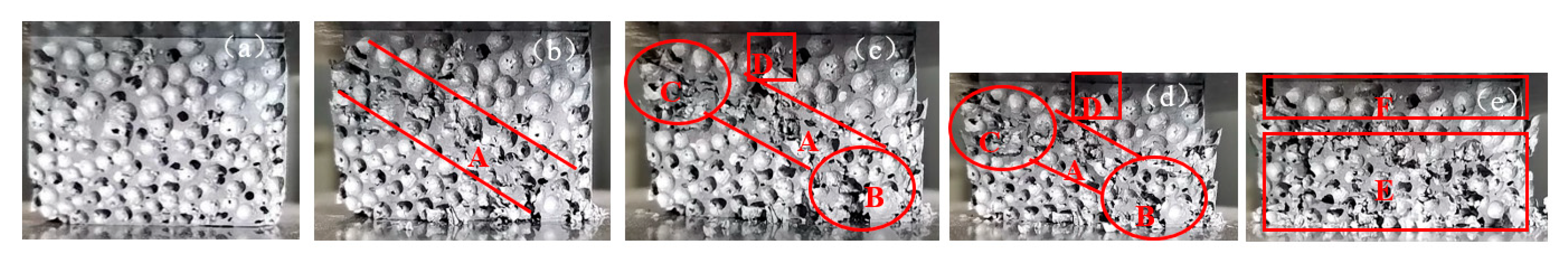
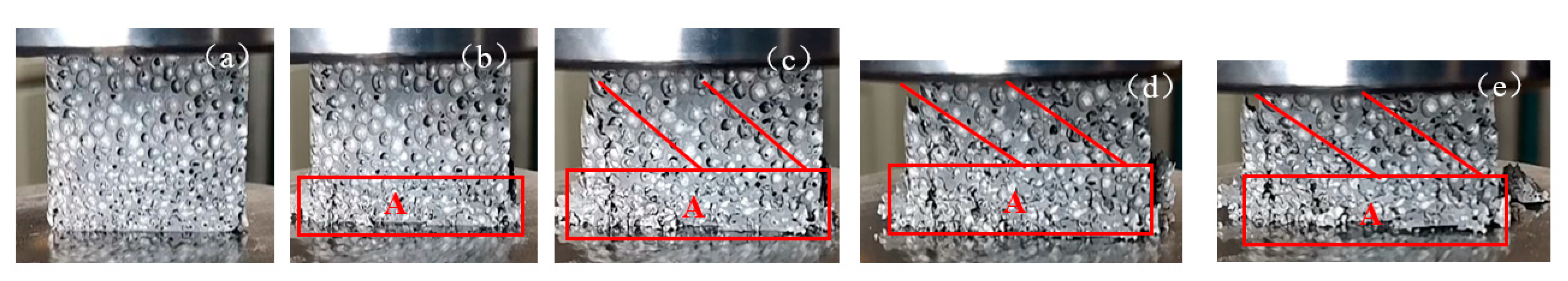
3.3. Analysis of Deformation Process of Two-Layered Sample

Figure 5 shows the macroscopic diagram of the deformation process of two-layered gradient Al foams with a cell size of 4-3. Figure 5a shows the deformation of two-layered gradient Al foams with a cell size of 4-3 in the elastic stage of the deformation process. It can be observed that the cell diameter of the upper part is 4 mm, and the cell diameter of the lower part is 3 mm, and there is no damage as a whole. From the deformation in Figure 5b–d, it can be observed that shear deformation occurred at the initial stage of collapse, as shown in A. In addition, an obvious brittle fracture can be observed in the cells, which is different from the ductile fracture of aluminum foam prepared by the melt foaming method. Therefore, the compression curves had obvious fluctuation. As the progress of compression continued, obvious local regional collapse deformation appeared at both ends of area A, as shown in areas B and C in Figure 5c,d. Moreover, the damage in this area gradually extended to other weak areas, as shown in area D in Figure 5c,d. Figure 5e shows the macroscopic deformation diagram of the cell structure in the later period of compression. It can be seen that the cell structures with a diameter of 3 mm in Zone E and some adjacent cell structures with a diameter of 4 mm have both obviously collapsed. In the area where the cell diameter is 4 mm in the F region, the overall cell shape was still intact. By comparing E and F, it can be found that the structure with cell diameter of 4 mm had higher strength than that with cell diameter of 3 mm.
Figure 6 shows a macroscopic view of the deformation process of two-layered gradient Al foams with cell diameter of 4-2. Figure 6a shows the deformation of two-layered gradient Al foams with a cell diameter of 4-2 in the elastic stage during the deformation process. In Figure 6a, the cell diameter of the upper part was 4 mm, and the cell diameter of the lower part was 2 mm. It can be observed that the cell wall in area A was thinner than that in area B, which belonged to the weak zone. From the deformation in Figure 6b–d, it can be observed that compression collapse deformation occurred in region C, which was consistent with the weak area in Figure 6a. Figure 6e shows a macroscopic view of cell structure deformation at the late compression stage. As can be seen from the figure, the shear deformation occurred in the area with a cell size of 4 mm. In the D area, the cell structure with a cell diameter of 2 mm and the adjacent part with a cell diameter of 4 mm have obviously collapsed. In the E area, the cell structure with a cell diameter of 4 mm remained intact as a whole. By comparing the D and E regions, the structure with a cell diameter of 4 mm had higher strength than the structure with a cell diameter of 2 mm. It can be seen that the deformation and collapse process occurred first in the weak link area with a small cell diameter.
Figure 7 shows a macroscopic view of the deformation process of two-layered gradient Al foams with a cell diameter of 3-2. Figure 7a shows the deformation of two-layered gradient Al foams with a cell diameter of 3-2 in the elastic stage during the deformation process. It can be observed that the upper part of the cell diameter was 3 mm, and the lower part was 2 mm. From the deformation in Figure 6b–d, the compression collapse deformation first appeared in area A, i.e., the area with a cell diameter of 2 mm, and then extended to the area with a cell diameter of 4 mm in the form of shear deformation. Figure 6e shows a macroscopic diagram of cell structure deformation at the later stage of compression. In zone A, the cell structure with a cell diameter of 2 mm and some adjacent cell structures with a cell diameter of 4 mm have undergone obvious collapse. In the area with a cell diameter of 4 mm, the cell was still intact as a whole.
Combined with the analysis in Figure 5, Figure 6 and Figure 7, the layered gradient aluminum foams prepared by a powder sintering method had obvious brittle deformation. When the cell diameter was 4-2 and 3-2, obvious deformation first appeared in the weak area with a cell diameter 2 mm, and then it extended into the area with a cell diameter of 4 mm and 3 mm in the form of shearing. When the cell diameter was 4-3, the shear deformation occurred first, and then the local collapse began at both ends of the shear deformation. When entering the later stage of deformation, the gradient Al foams collapsed obviously in the relatively small cell-size area, while the relatively large cell size area still kept the complete structure. Therefore, it can be concluded that the collapse deformation process of two-layered gradient Al foams firstly occurs in the relatively weak area of small cell size. Then this induces the deformation of the relatively weak area of large cell size to extend to the large cell-size area. In addition, the strength of the large cell-size area is generally greater than that of the small cell size area. The results show that the aluminum powder particles in the layered gradient Al foams prepared by powder metallurgy are easier to aggregate in the large cell-diameter area. This makes the cell wall thicker in the large cell-diameter area, and the cell wall in the area with a cell diameter of 2 mm is too thin.

4. Conclusions

The effects of cell size on the quasi-static compressive behavior of SGAF have been investigated. Meanwhile, deformation and failure mechanisms for the compressive test were also discussed. The conclusions were drawn as follows.
  • Gradient Al foams (i.e., the cell size of 4-3, 4-2, 3-2) were successfully prepared by the powder metallurgy method using environmentally friendly, non-toxic and harmless sodium thiosulfate particles.
  • In the layered gradient Al foams prepared by the powder metallurgy method, aluminum powder particles are easier to aggregate in the large cell-diameter area. This makes the cell wall with the large cell-diameter thicker, while the cell wall with the small cell-diameter is relatively thinner. This makes for better mechanical properties of the layered gradient Al foams with a large cell diameter. When the cell sizes of the samples were 4 mm-3 mm, 4 mm-2 mm, 3 mm-2 mm, the peak stress was 6.2 MPa, 5.2 MPa and 3.5 MPa respectively.
  • Gradient Al foams prepared by powder metallurgy show obvious brittle deformation. This is caused by the melting and bonding characteristics of aluminum powder particles during sintering. When the cell sizes of the samples were 4 mm-3 mm, 4 mm-2 mm, 3 mm-2 mm, the corresponding stress drop ratio was 55.2%, 40.4%, 20.3%.
  • In the process of deformation, the weak area with a relatively smaller cell diameter is more likely to collapse and deform. Then, this leads to the deformation of the weak area with a relatively thin cell wall in the large cell-diameter area. At the later stage of deformation, when the area with a smaller cell diameter collapsed completely, the area with larger cell diameter still kept a relatively complete cell structure.

Author Contributions

W.H. and Y.W. are in charge of data curation. G.L. is in charge of funding acquisition. W.H. wrote the original draft. H.L. and F.W. reviewed and edited the manuscript. All authors have read and agreed to the published version of the manuscript.

Funding

This work was financially supported by Science and Technology Innovation Fund of Higher Education in Shanxi Province, China (No. 2020L0342), Doctoral Foundation of Taiyuan University of Science and Technology (No. 20192066), Research Funding for Doctors in Shanxi Province (No. 20202021), Natural Science Foundation of Shanxi Province (No. 201901D111241, 201901D111270), Open project of EPM Laboratory, Northeastern University (No. NEU-EPM-014).

Data Availability Statement

Not applicable.

Conflicts of Interest

The authors declare no conflict of interest.

References

  1. Ashby, M.F.; Evans, A.G.; Fleck, N.A.; Gibson, L.J.; Hutchinson, J.W.; Wadley, H.N.G. Metal Foams: A Design Guide; Elsevier Science: Amsterdam, The Netherlands, 2000. [Google Scholar]
  2. Gibson, L.J. Mechanical behavior of metallic foams. Ann. Rev. Mater. Res. 2000, 30, 191–227. [Google Scholar] [CrossRef]
  3. Atwater, M.A.; Guevara, L.N.; Darling, K.A.; Tschopp, M.A. Solid State Porous Metal Production: A Review of the Capabilities, Characteristics, and Challenges. Adv. Eng. Mater. 2018, 20, 1700766. [Google Scholar] [CrossRef] [Green Version]
  4. Duan, Y.; Ding, Y.; Liu, Z.Y.; Hou, N.; Zhao, X.H. Effects of cell size vs. cell-wall thickness gradients on compressive behavior of additively manufactured foams. Compos. Sci. Technol. 2020, 99, 1–11. [Google Scholar] [CrossRef]
  5. Sun, Y.; Li, Q.M. Dynamic compressive behaviour of cellular materials: A review of phenomenon, mechanism and modelling. Int. J. Impact Eng. 2018, 112, 74–115. [Google Scholar] [CrossRef] [Green Version]
  6. Kincses, D.B.; Károly, D.; Bukor, C. Production and testing of syntactic metal foams with graded fillervolume. Mater. Today Proc. 2021, 45, 4225–4228. [Google Scholar] [CrossRef]
  7. Linul, E.; Lell, D.; Movahedi, N.; Codrean, C.; Fiedler, T. Compressive properties of zinc syntactic foams at elevated temperatures. Compos. Part B Eng. 2019, 167, 122–134. [Google Scholar] [CrossRef]
  8. Fiedler, T.; Al-Sahlani, K.; Linul, P.A.; Linul, E. Mechanical properties of A356 and ZA27 metallic syntactic foams at cryogenic temperature. J. Alloys Compd. 2020, 813, 152181. [Google Scholar] [CrossRef]
  9. Bastawros, A. Experimental analysis of deformation mechanisms in a closed-cell aluminum alloy foam. J. Mech. Phys. Solids 2000, 48, 301–322. [Google Scholar] [CrossRef]
  10. Deshpande, V.S.; Fleck, N.A. Isotropic constitutive models for metallic foams. J. Mech. Phys. Solids 2000, 48, 1253–1283. [Google Scholar] [CrossRef] [Green Version]
  11. Ouellet, S.; Cronin, D.; Worswick, M. Compressive response of polymeric foams under quasi-static, medium and high strain rate conditions. Polym. Test. 2006, 25, 731–743. [Google Scholar] [CrossRef]
  12. Huang, W.Z.; Luo, H.J.; Mu, Y.L.; Xu, J.R.; Zhao, A.C. Dynamic Compressive Property of Closed-Cell Mg Alloy Composite Foams Reinforced with SiC Particles. Acta Metall. Sin. 2019, 32, 1320–1328. [Google Scholar] [CrossRef] [Green Version]
  13. Kennedy, A.R.; Asavavisitchai, S. Effects of TiB2 particle addition on the expansion, structure and mechanical properties of PM Al foams. Scr. Mater. 2004, 50, 115–119. [Google Scholar] [CrossRef]
  14. Guden, M.; Yukse, I.S. SiC-particulate aluminum composite foams produced from powder compacts: Foaming and compression behavior. J. Mater. Res. 2006, 41, 4075–4084. [Google Scholar] [CrossRef] [Green Version]
  15. Mu, Y.L.; Yao, G.C.; Zu, G.Y.; Cao, Z.K. Influence of strain amplitude on damping property of aluminum foams reinforced with copper-coated carbon fibers. Mater. Des. 2010, 31, 4423–4426. [Google Scholar] [CrossRef]
  16. Liu, C.S.; Zhu, Z.G.; Han, F.S.; Banhart, J. Internal friction of foamed aluminium in the range of acoustic frequencies. J. Mater. Sci. 1998, 33, 1769–1775. [Google Scholar] [CrossRef]
  17. Han, F.S.; Zhu, Z.G.; Shi, C.Y.; Wang, Y. Study on the damping characteristics of foamed aluminum. Acta Phys. Sin. 1998, 47, 1161–1170. [Google Scholar]
  18. Mu, Y.L.; Yao, G.C.; Luo, H.J. The dependence of damping property of fly ash reinforced closed-cell aluminum alloy foams on strain amplitude. Mater. Des. 2010, 31, 1007–1009. [Google Scholar] [CrossRef]
  19. Hangaia, Y.; Andoa, M.; Ohashia, M.; Amagaia, K.; Suzukia, R.; Matsubaraa, M.; Yoshikawa, N. Compressive properties of two-layered aluminum foams with closed-cell and open-cell structures. Mater. Today Commun. 2020, 24, 101249. [Google Scholar] [CrossRef]
  20. He, S.Y.; Lv, Y.N.; Chen, S.T.; Dai, G.; Liu, J.G.; Huo, M.K. Gradient regulation and compressive properties of density-graded aluminum foam. Mater. Sci. Eng. A 2020, 772, 138658. [Google Scholar] [CrossRef]
  21. Yu, X.; Qin, Q.; Zhang, J.; He, S.; Xiang, C.; Wang, M.; Wang, T.J. Crushing and energy absorption of density-graded foam-filled square columns: Experimental and theoretical investigations. Compos. Struct. 2018, 201, 423–433. [Google Scholar] [CrossRef]
  22. Pollien, A.; Conde, Y.; Pambaguian, L.; Mortensen, A. Graded open-cell aluminium foam core sandwich beams. Mater. Sci. Eng. A 2005, 404, 9–18. [Google Scholar] [CrossRef] [Green Version]
  23. Hassani, A.; Habibolahzadeh, A.; Bafti, H. Production of graded aluminum foams via powder space holder technique. Mater. Des. 2012, 40, 510–515. [Google Scholar] [CrossRef]
  24. Movahedi, N.; Orbulov, I.N.; Kemény, A.; Belova, I.V.; Murch, G.E.; Fiedler, T. Fatigue characterization of functionally graded ZA27 alloy syntactic foams. Mater. Sci. Eng. A 2020, 798, 140255. [Google Scholar] [CrossRef]
  25. Movahedi, N.; Vesenjak, M.; Krstulović-Opara, L.; Belova, I.V.; Murch, G.E.; Fiedler, T. Dynamic compression of functionally-graded metal syntactic foams. Compos. Struct. 2021, 261, 113308. [Google Scholar] [CrossRef]
  26. Yang, J.; Wang, S.; Ding, Y.; Zheng, Z.; Yu, J. Crashworthiness of graded cellular materials: A design strategy based on a nonlinear plastic shock model. Mater. Sci. Eng. A 2017, 680, 411–420. [Google Scholar] [CrossRef]
  27. Li, L.; Han, B.; He, S.-Y.; Zhao, Z.-Y.; Zhang, R.; Zhang, Q.-C.; Lu, T.J. Shock loading simulation using density-graded metallic foam projectiles. Mater. Des. 2019, 164, 107546. [Google Scholar] [CrossRef]
  28. Chang, B.; Zheng, Z.; Zhang, Y.; Zhao, K.; He, S.; Yu, J. Crashworthiness design of graded cellular materials: An asymptotic solution considering loading rate sensitivity. Int. J. Impact Eng. 2020, 143, 103611. [Google Scholar] [CrossRef]
  29. Zhang, J.; Wang, Z.; Zhao, L. Dynamic response of functionally graded cellular materials based on the Voronoi model. Compos. Part B Eng. 2016, 85, 176–187. [Google Scholar] [CrossRef]
  30. Jain, H.; Gupta, G.; Kumar, R.; Mondal, D.P. Microstructure and compressive deformation behavior of SS foam made through evaporation of urea as space holder. Mater. Chem. Phys. 2019, 223, 737–744. [Google Scholar] [CrossRef]
  31. Sazegaran, H.; Hojati, M. Effects of copper content on microstructure and mechanical properties of open-cell steel foams. Int. J. Miner. Metall. Mater. 2019, 26, 588–596. [Google Scholar] [CrossRef]
  32. Hangai, Y.; Minh, N.N.; Morita, T.; Suzuki, R.; Matsubara, M.; Koyama, S. Cutting process for aluminum foam fabricated by sintering and dissolution process. Adv. Powder Technol. 2017, 28, 1426–1429. [Google Scholar] [CrossRef]
Figure 1. Macrostructure of two-layered cell-size gradient Al foams in both orthogonal direction; transverse direction: Al foams with cell of (a) 2 mm, (b) 3 mm, (c) 4 mm, longitudinal direction: Al foams with cell of (d) 3 mm-2 mm, (e) 4 mm-2 mm, (f) 4 mm-3 mm, A—aggregation of aluminum powders, B—weak connection of cells.
Metals 11 01337 g001
Figure 2. The microstructure of a two-layered gradient aluminum foamed cell wall under a metallographic microscope at different scales with of (a) 100 μm, (b) 40 μm, (c) and (d) 20 μm: A—clear boundary line, B—better boundary combination.
Metals 11 01337 g002
Figure 3. The microstructure of a two-layered gradient aluminum foamed cell wall under a scanning electron microscope at different scales with of (a) 40 μm and (b) 20 μm: A—gaps between particles, B—bent and interlocked boundary.
Metals 11 01337 g003
Figure 4. The compressive curves of two-layered structure Al foams with different cell-size gradients (4-3, 4-2, 3-2).
Metals 11 01337 g004
Figure 5. The macroscopic diagram of the deformation process of two-layered gradient Al foams with a cell size of 4-3. Deformation strain: (a) ε = 0.01, (b) ε = 0.08, (c) ε = 0.21, (d) ε = 0.38, (e) ε = 0.46; A indicates shear deformation, B and C indicate local regional collapse deformation, D indicates the damage extended to other weak areas, E indicates obviously collapsed area, F indicates still intact overall cell shape.
Metals 11 01337 g005
Figure 6. A macroscopic diagram of the deformation process of two-layered gradient Al foams with a cell size of 4-2. Deformation strain: (a) ε = 0.01, (b) ε = 0.08, (c) ε = 0.21, (d) ε = 0.38, (e) ε = 0.46; A indicates the area with thin cell wall, B indicates the area with relatively thick cell wall, C indicates local regional collapse deformation, D indicates obviously collapsed area, E indicates still intact overall cell shape.
Metals 11 01337 g006
Figure 7. A macroscopic diagram of the deformation process of two-layered gradient Al foams with a cell size of 3-2. Deformation strain: (a) ε = 0.01, (b) ε = 0.08, (c) ε = 0.21, (d) ε = 0.38, (e) ε = 0.46; A indicates the obvious collapse area.
Metals 11 01337 g007
Table 1. The mechanical properties of the samples with different cell sizes.
Performance Peak Stress/MPaPlateau Stress/MPaStress Drop Rate/%
Samples
4-36.23.955.2
4-25.23.540.4
3-23.53.520.3
Publisher’s Note: MDPI stays neutral with regard to jurisdictional claims in published maps and institutional affiliations.

