Abstract
In molten carbonate fuel cell (MCFC) systems, it is known that the shape of corrugated plates has a significant influence on performance, durability, and cost. A corrugated plate with a repeating open trapezoidal-shaped slot supports membrane electrode assembly and provides a gas flow channel. To increase the efficiency of the MCFC, the slot between the corrugated and center plates has a relatively large contact length. However, increasing the contact length of the slot increases the risk of necking or fracture generation at the corner of the slot. Therefore, we focus on the development of forming technology of corrugated plate which has large contact length of slots without any necking or fracture. To this end, numerical simulation was conducted to determine the appropriate process and tool design. In the simulation, to capture shear fracture during the forming process of slots, the normalized Cockroft–Latham ductile fracture model was used. The critical value for slitting and fracture was evaluated by comparing the deformed shapes in the slitting plane obtained from experimental and simulation results. Based on simulation results, a reasonable design concept of the two-stage forming process was suggested to increase the contact length of the slot without necking or fracture. In addition, the experiment results confirmed the validity of the proposed forming process and tool design.
1. Introduction
Molten carbonate fuel cells (MCFCs) are in the spotlight as a new energy source to replace fossil fuels because they are thermally and electrically efficient and environmentally friendly. Unlike low temperature fuel cells, which can use platinum electrodes, MCFCs can use non-precious metals such as nickel as electrode catalysts since they operate at high temperatures of 650 °C and above. However, there is a limitation in finding materials for the corrugated plate of MCFCs which needs both high corrosion resistance and mechanical strength for use at high temperatures [1,2]. For this reason, stainless steel is usually used as a material for the corrugated plate of MCFCs.
MCFC stack is composed of hundreds of cell packages consisting of bipolar plates and membrane electrode assemblies, as shown in Figure 1. The anode and cathode corrugated plates form a bipolar plate with a center plate. To increase the power density of such a cell, the thickness of the bipolar plate should be minimized. Therefore, thin plates with micrometer thickness are used as bipolar plates.
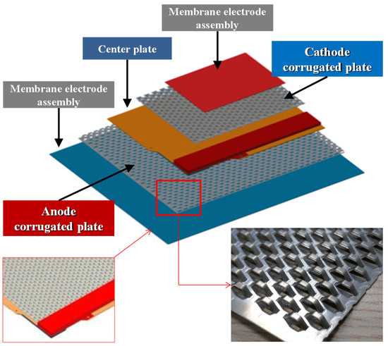
Figure 1.
Illustration of a unit cell package consisting of membrane electrode assemblies, corrugated plates, and a center plate.
The corrugated plates that support membrane electrode assemblies have a repeating open trapezoidal pattern to provide channels for gas and water flow, as well as a path for electrolyte flow between the cathode and anode [1,2,3,4]. Enhanced fuel cell efficiency can be achieved by enlarging the area of the flow channel of a unit slot for a substantially high gas flow rate and by increasing the contact length between the electrode components and the slot [4,5]. However, the forming process of metallic bipolar plates limits the depth of the flow channel because bipolar plates can be damaged during the forming process if the conditions are excessively extreme [6]. Such damage is especially acute for corrugated plates with micrometer thickness because slitting and forming must be simultaneously performed to produce the open trapezoidal pattern, and the corner of the slot would be vulnerable to fracture owing to concentrated deformation during the forming process.
Therefore, the prediction of deformations in the slitting process, which entails shear deformations, is essential for designing the forming process of the MCFC corrugated plates. Among the earlier studies on shear deformation, Li et al. [7,8] performed an experimental study on the formation of burrs and fractures during the shearing of aluminum sheets. Theoretical and experimental studies on the blanking processes of aluminum, copper, and bronze were carried out by Ghosh et al. [9]. Further, there have been several efforts to clarify the phenomena related to the shear deformation by combining finite element (FE) analysis and ductile fracture criteria. The first FE analysis of shear deformation was performed by Taupin et al. [10], who conducted an FE analysis of the blanking process using the fracture model and element deletion method suggested by McClintock [11]. In addition, Fang et al. [12] simulated the blanking process of aluminum based on the Cockroft-Latham ductile fracture model [13]. Klingenberg and Singh [14] performed an FE analysis of punching/blanking processes by applying the Tvergaard–Gurson model [15,16,17] and predicted ductile fractures caused by the formation and growth of voids. Ghosh et al. [18] applied the Tvergaard–Gurson model, the Cockroft–Latham model, and a shear failure model to the analysis of the slitting process of an aluminum alloy and compared the simulation results with experimental ones. Recently, Meng et al. [19] compared the accuracy of different models [13,20,21,22] of shearing and blanking in the micro-forming of a plunged part using pure copper sheets. Research on the forming process of an MCFC corrugated plate was conducted by Lee et al. [4] and Yang et al. [5]. They adopted a three-stage forming process to avoid the local concentration of deformations and to prevent fracture. Although many studies have focused on process design based on FE analysis and experimental results, there are only a few reports on increasing the contact length of the slot of the corrugated plates to enhance the electrical efficiency.
Thus, in this study, a three-dimensional FE analysis of one-stage and two-stage forming processes was conducted based on a ductile fracture model to increase the contact length of the slot for the corrugated plate. The Cockroft–Latham model, which is known to be appropriate for shear and tensile deformation analysis among ductile fracture criteria, was employed in the FE analysis. To obtain the critical damage value used in the FE analysis, slitting experiments were performed to form an open trapezoidal-shaped slot. The slitting experiment was performed at different forming heights. The slitting plane of the slot at each forming height was analyzed using optical microscopy. The critical damage value was determined by comparing the deformed shapes of the slitting plane obtained from experimental and simulation studies. Based on the critical damage value, FE investigations of various parameters such as punch and die corner radii, forming height, and slot angle were performed to determine the appropriate process and tool design for enlarging the contact length of the slot without any necking and fracture. Finally, a corrugated plate was formed using the suggested forming process and tool design. The experimental observations were compared with the simulation results to confirm the validity of the proposed forming process and tool design.
2. Determination of Critical Damage Value
Experimental and FE analyses of the slitting process using different forming heights were performed to determine the critical damage value. To this end, the slitting plane of the slot obtained from the simulation using different critical damage values was compared with the experimental one.
2.1. Experimental
AISI 310S stainless steel with a thickness of 300 μm was used in this study. The experiments were carried out in a mechanical servo press (H1F80, Komatsu, Tokyo, Japan) with a capacity of 80 tons, and stroke was controlled in the micrometer range. The punch moved with a sinusoidal motion owing to the crank motion. During the forming process, the press was operated from 15.7 mm/s in the vertical direction at the onset of forming to 0.0 mm/s at the bottom dead point, and the average speed of the punch was 7.9 mm/s. During the experiment, a 30-μm-thick Teflon film was used to minimize the friction effect between the punch and sheet metal. Initial designs of the punch and die and die-set in servo-press used in the experiments were shown in Figure 2. The die-set composed a punch assembly at the top and a die assembly at the bottom. The sheet metal is inserted on the left side of the setup as shown in the figure. A progressive process consisting of punching to creates a hole for the guide pin at each side of the sheet, subsequent two-stage forming of the slot, and final cutting, was employed.
Figure 2.
(a) Initial design of punch and die and (b) experimental setup for progressive two-stage forming.
The slitting experiments were conducted with various forming heights to analyze the slitting plane and deformation pattern. Figure 3 shows the cross-sectional shapes of the slots according to the forming height. Note that the cross-sections are perpendicular to the longitudinal direction (y-direction) of the slots. The forming height of the slot is shown in the figure. Notably, a rounded plane, a subsequent straight plane, and a tilted plane were formed during slitting. These planes can be classified into three regions, namely, the rollover, burnish, and fracture regions in a slitting process with shear deformation [7]. The detailed deformed shape of the slot and the lengths of the rollover, burnish, and fracture regions in the slitting plane are shown in Figure 3e,f, where H and C indicate the forming height and clearance between the punch and die, respectively. A clearance of 19.1 μm was measured, which is lower than the designed clearance of 25.0 μm. The length of rollover region is almost maintained during slitting because rollover generally occurs as a consequence of the elastic and plastic deformations at the beginning of the slitting process [10]. The length of the fracture region was measured to be approximately 85 μm. This means that the fracture occurs at a forming height of approximately 215 μm.
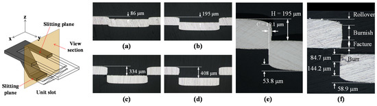
Figure 3.
Cross-sectional shapes of slots according to forming height: (a) 86 μm, (b) 195 μm, (c) 334 μm, and (d) 408 μm; (e) magnified view of (b), and (f) magnified view of (d).
Figure 4 shows the cross-sectional shapes of the slots at forming heights of 1.63 and 1.97 mm. The deformations of the upper and lower parts of slots were almost symmetric. The forming height has no direct effect on the deformed shape and length in the slitting plane. In Figure 5, lengths of the rollover, burnish, and fracture regions are shown. The lengths in the figure were measured at five points in the lower part of the slots along the longitudinal direction. The hatch represents the lower and upper bounds of the lengths in the slitting plane.
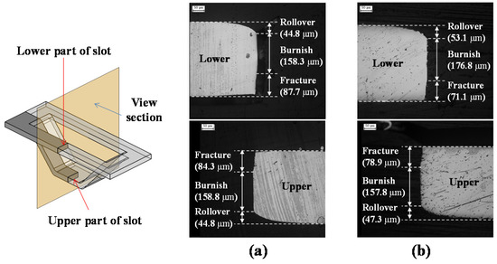
Figure 4.
Cross-section shapes of slots and lengths in slitting plane with different forming heights: (a) 1.63 and (b) 1.97 mm.
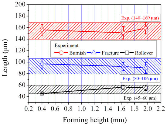
Figure 5.
Variation of lengths in slitting plane according to forming height.
2.2. FE Analysis
In the slitting process, a shear band is generally formed in the clearance between the punch and the die. When a sufficient external force is applied to the sheet material, the shear stress in the material exceeds the ultimate shear strength, resulting in the fracture of the sheet material. In the FE analysis of the shear process, such as the slitting of materials with good ductility, material fracture occurs in the center of the shear band because the element is distorted and excessive shearing force is applied on the element. This phenomenon does not correspond to the onset of fracture that occurs at the edge point of the punch and die [23,24]. To avoid the aforementioned problem, the commercial finite element analysis software FORGE (2011, Transvalor, Paris, France), which is capable of remeshing element and element deletion, was used in this study. In the forming simulation, the normalized Cockroft–Latham ductile fracture model [21,25,26], which is expressed in Equation (1), was adopted to determine the criterion for fracture during the slitting process. During the simulation, the element was deleted in the FE model when the damage accumulated in the material exceeded the critical damage value D:
where is fracture strain, is maximum principal stress, is equivalent stress and is equivalent strain.
As shown in Figure 6, a quarter model was used in the simulation to minimize computation time. Symmetric boundary conditions were applied to the boundaries of the quarter model. The tetrahedral element was utilized in the FE analysis, in which the average element size was approximately 50 μm. To appropriately capture the fracture initiation and propagation, an element of size 10~20 μm was used in the slitting region. A Coulomb friction model with a coefficient of 0.02 was assumed. The punch and die were considered as rigid bodies. The FE analysis was conducted with an average punch speed of 7.9 mm/s due to no significant effect of strain rate sensitivity on the deformation behavior as indicated in [27].
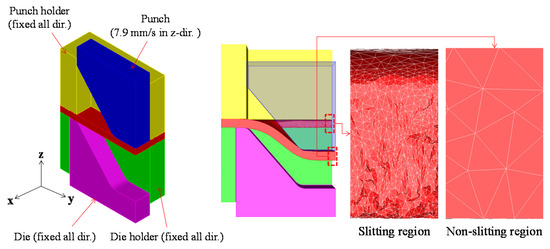
Figure 6.
Quarter model and boundary condition for FE analysis.
The flow stress for the numerical simulation was acquired from a tensile test based on the ASTM standard. For the tensile test, specimens with a gauge length of 50.0 mm, width of 12.5 mm, and thickness of 0.3 mm were prepared by cutting. The tensile direction of the specimen was parallel to the rolling direction of the sheet material. The tensile test was conducted using Universal Tensile Machine (R&B, Daejeon, Korea) with a capacity of 10 ton with a testing speed of 0.05 mm/s at the room temperature. The displacement was measured using a laser extensometer and converted into strain. In the simulation, the stress-strain curve fitted by the Swift equation as expressed in Equation (2) was used. Owing to the difficulties of the shearing test for sheet metal with submillimeter thickness, the isotropy of a material was assumed and the von Mises isotropic yield function was used in the simulation:
Typically, a tensile test is used to determine the damage value [12,18,19,21]. However, estimating the damage value from tensile tests is not reliable if the shear deformation is dominant because the stress state of the shear deformation is different from the tensile test. In other words, most of the deformed region of the shearing process is in a state of shearing and compression, whereas those of the tensile test are in a state of tension [28]. Thus, the critical damage value for the slitting process must be evaluated by comparing the slitting planes obtained from the simulations and experiments [4].
The lengths in the slitting plane obtained from the FE results according to the critical damage value are summarized and compared with the experimental results in Figure 7. With an increase in the critical damage value, the length of the burnish region increased, while the length of the fracture region decreased. Notably, the length of the rollover region barely changes according to the critical damage value. A comparison of simulation and experimental results revealed that the critical damage value of 3.6, which is significantly reasonable because the lengths in the slitting plane obtained from the simulation were in good agreement with the experimental results.
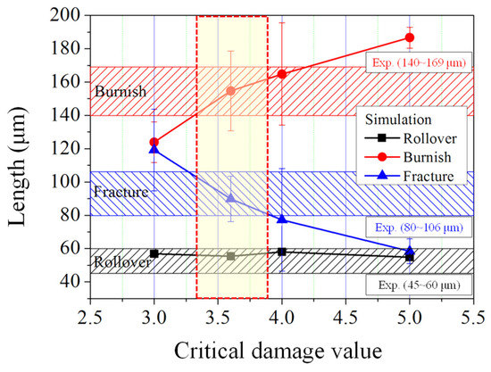
Figure 7.
Comparisons of lengths in slitting plane obtained from FE analysis and experiment according to the critical damage value.
To verify the predicted critical damage value, the cross sections of the slot, which are perpendicular and parallel to the longitudinal direction of the slot, obtained from the FE analysis and experiments, are compared in Figure 8. The predicted lengths were in good agreement with the experimental values, except for the length of the rollover region for the upper slot. In Figure 8c,d, the deformed shape and thickness distribution of the slot at a forming height of 1.63 mm were compared. The predicted thickness, particularly in the inclined part of slot (266 μm), is good agreement with experimental results. Thus, it was assumed that the extrapolated stress-strain curve by Swift equation well simulated material behavior in the large strain range. The predicted thickness at the corner of the slot was only 4% lower than the experimental value. It can be observed in Figure 8d that necking occurred at the corner of the slot when the thickness reached 205 μm. For the conservative design, a thickness of 200 μm at the corner of the slot was regarded as fracture or necking in the simulation because of insufficient plate strength and numerical error.
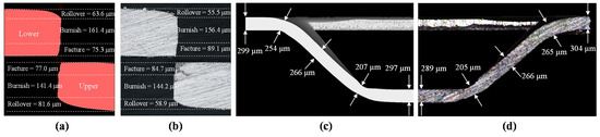
Figure 8.
Comparison of deformed shapes in cross section view via (a) FE analysis with critical damage value of 3.6 and (b) experiment at forming height of 408 μm; (c) FE analysis with a critical damage value of 3.6 and (d) experiment at forming height of 1.63 mm.
3. Tool Design for Increasing Contact Length of the Slot
Herein, FE analyses with a critical damage value of 3.6 were conducted to suggest an appropriate forming process and tool design for increasing the contact length between the corrugated plates and electrodes. It is crucial to increase the contact length because it has a considerable effect on the efficiency of the current collection. Therefore, first, in the one-stage forming process, the effect of design parameters on the formability and contact length was investigated. Then, the two-stage forming process of a corrugated plate with maximum contact length was designed based on the numerical results of the one-stage forming process. Finally, the numerically obtained design for the maximum contact length was experimentally verified.
3.1. One-Stage Forming Process
Although the most effective way to increase the contact length is to make a steep slope of the slot, it causes necking or fracture at the corner of the slot. This can be avoided by increasing the corner radius of the slot. However, this increased corner radius reduces the contact length in other ways. Therefore, the effect of slope angle and corner radius on the contact length and formability was investigated in a one-stage forming process. The slope angles (A1) of 50°, 60°, and 70° and corner radii (R1p) of 0.6, 0.9, and 1.2 mm were selected as design parameters. It can be seen that these values are higher than those in the initial design (Figure 2a).
Figure 9 shows the deformed shape of the slot according to the slope angle and corner radius. It was assumed that necking and fracture simultaneously occurred when the thickness of the slot is smaller than 200 μm, which is two-thirds of the initial thickness (300 μm); This is because the fracture occurred rapidly right after necking in the tensile tests of AISI 310S used in this study. Necking and fracture occurred in the case of a higher slope angle and smaller corner radius.
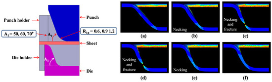
Figure 9.
Design parameters used in FE analysis of one-stage forming and simulation results according to the design parameters: slope angle of (a) 50°, (b) 60°, and (c) 70° and corner radius of (d) 0.6 mm, (e) 0.9 mm, and (f) 1.2 mm.
Figure 10 shows the effect of slope angle and corner radius of punch on the minimum thickness and contact length of the slot in one-stage forming, where the definition of contact length was given in the figure. The thickness of the slot increases with increasing corner radius. In a case, when the slope angle is 50° and the corner radius is 1.2 mm, the maximum thickness at the corner of the slot was predicted to be 250 μm which is 21% higher than that of the initial design at a forming height of 1.63 mm. In contrast, the contact length slightly decreased with the increasing corner radius. The effect of the slope angle of the slot on the contact length was more dominant than that of the corner radius. The contact length is rapidly increased with increasing slope angle of the slot. For example, when the corner radius and slope angle are 1.2 mm and 70° respectively, the slot exhibited maximum contact length, except in the case with fracture and necking generation. However, this case is vulnerable to necking and fracture generation because the minimum thickness of the slot was adjacent to the critical value.
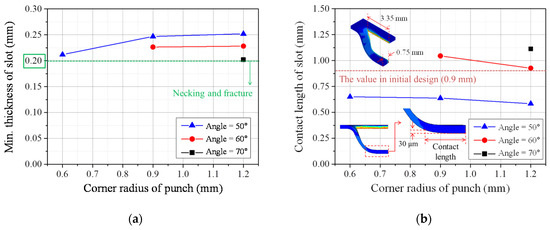
Figure 10.
Effect of slope angle and corner radius of punch on (a) minimum thickness and (b) contact length of the slot in one-stage forming.
3.2. Two-Stage Forming Process
The two-stage forming process is comprised of slitting-preforming and final forming. Figure 11 shows the design parameters used in the simulation of the two-stage forming. Based on the FE simulation results of one-stage forming, a slope angle of 70° for final forming was selected to increase the contact length of the slot, even though this higher angle might accelerate the necking or fracture regardless of the corner radius of the punch. To prevent necking or fracture at the corner of the slot caused by the high slope angle at the final forming, a lower slope angle and forming height were selected for slitting-preforming compared to the final forming. Here, the corner radius of slot was fixed at 1.2 mm.
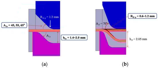
Figure 11.
Design parameters of two-stage forming process: (a) slitting-preforming and (b) final forming.
In Figure 12, the deformed shapes of the slot in the slitting-preforming simulation are compared according to the design parameter. In this figure, the columns with gray color indicate the simulation results with tearing at the side of the slope. From the simulation, it was found that the tearing of the slot is easily generated in cases with a small slope angle and low forming height in the slitting-preforming stage. In other words, the tearing can be expected when the slitting does not occur smoothly owing to the high material flow resistance during slitting-preforming.
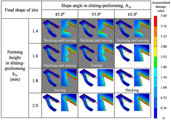
Figure 12.
Deformed shapes in the slitting-preforming simulation according to the slope angle and forming height.
The effects of the slope angle and forming height in the slitting-preforming on the minimum thickness and contact length of the slot after the final forming are summarized in Figure 13. The minimum thickness of the slot increases with the forming height in the slitting-preforming stage. An increase in the minimum thickness of the slot prevents potential fracture or necking at the corner of the slot. On the other hand, the effect of the slope angle is negligible. As shown in Figure 13b, the contact length increased when the slope angle increased in the slitting-preforming stage. In contrast, it decreased slightly with the increasing the forming height. It can be seen that the contact length increased by 15–20% compared to the initial design.
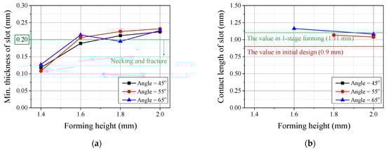
Figure 13.
Changes in (a) minimum thickness and (b) contact length of the slot in the slitting-preforming process according to slope angle and forming height.
Figure 14 shows the changes in the minimum thickness and contact length of the slot according to the corner radius of the punch in the final forming process. In the final forming simulation, a forming height of 2.0 mm and a slope angle of 65° were selected in the slitting-preforming process because the preform after the first stage using these parameters exhibits a relatively high value of minimum thickness and contact length of the slot. It can be observed that the minimum thickness slightly increases with the increasing corner radius of the punch, whereas the contact length decreases. Necking or fracture occurred in a case with a corner radius of 0.6 mm. In other cases, no necking or fracture was predicted. As shown in Figure 14, the risk for necking or fracture generation might be increased when the corner radius of the punch is small due to the decreased minimum thickness of the slot. For this reason, a 0.9 mm corner radius of punch was employed in final forming experiments to improve the contact length of the slot without any necking or fracture from a conservative view of design.
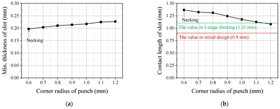
Figure 14.
Variations of (a) minimum thickness and (b) contact length of the slot in the final forming stage process with respect to the corner radius of the punch.
3.3. Experimental Validation of Two-Stage Forming Process and Tool Design
The experimental work was conducted to validate the two-stage forming process and tool design. The main parameters obtained from the simulation are as follows: R2s-p = 1.2 mm, h2s = 2.0 mm, and A2s = 65° in slitting-preforming, R2f-p = 0.9 mm, h2f = 2.05 mm and A2f = 70° in final forming. It can be confirmed from Figure 15 that a slot without any necking or fracture was successfully produced in the two-stage forming process, including slitting-preforming and final forming.
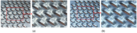
Figure 15.
Experimental results of the two-stage forming process: (a) slitting-preforming and (b) final forming.
The predicted and measured slot thicknesses after two-stage forming are compared in Figure 16. The minimum thickness at the corner of the slot was experimentally observed to be 222 μm, which is 74% of the initial thickness (300 μm). The maximum error between the predicted and measured values was less than 5.2%. The predicted contact length (1.24 mm) was overestimated by approximately 7.8% compared with the experimental value (1.15 mm). The contact lengths (1.24 and 1.15 mm) obtained from the simulation and experiment for two-stage forming were 38 and 28% longer than that (0.9 mm) of the initial design, respectively. The variation in the contact length and thickness at the corner of the slot in the experiments were ±57 and ±8 μm, respectively. Compared to other studies on the formation of corrugated plates [4,5,29], the slot fabricated by two-stage forming has a steep slot angle and a relatively large contact length at the same forming height.
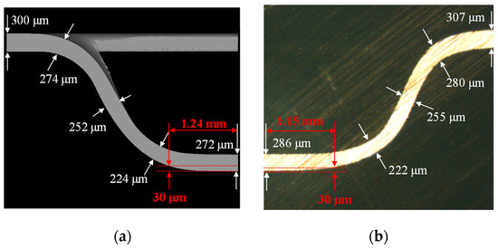
Figure 16.
Comparison of contact length and thickness distribution of slot for two-stage forming: (a) FE analysis and (b) experiment.
4. Conclusions
In this study, three-dimensional FE analyses with a ductile fracture model were conducted to determine the appropriate forming process and tool design related to the increasing slot contact length of the corrugated plate for MCFCs. Based on the FE simulation with the determined critical damage value, the two-stage forming and tool design were suggested to increase the contact length of the slot. Further, it was experimentally verified that the deformed shape was in good agreement with that obtained from the simulation. The detailed conclusions are summarized as follows.
- The ductile fracture criterion was obtained by comparing the deformed shapes in the slitting plane obtained from the simulation and experimental results.
- In the one-stage forming process, the contact length rapidly increased with the increasing slope angle and decreasing corner radius of the slot, while the minimum thickness decreased. Necking or fracture occurred when the thickness of the slot was less than two-thirds of the initial thickness.
- In the slitting-preforming stage of the two-stage forming process, the minimum thickness and contact length of the slot were increased by increasing the forming height and slope angle, respectively. In contrast, when both the slope angle and forming height were decreased, the tearing of the slot was observed.
- In the final forming stage of the two-stage forming process, decreasing the corner radius of the final punch reduced the thickness and increased the contact length of the slot. Necking or fracture occurred when the corner radius was minimal.
Author Contributions
Conceptualization, Y.-S.O. and S.-H.K.; Methodology, H.W.L. and S.-J.K.; Software, I.Y.M. and J.J.; Validation, I.Y.M., H.W.L. and S.-J.K.; Writing—original draft preparation, Y.-S.O.; Writing—review and editing, Y.-S.O. and J.J.; Visualization, I.Y.M.; Supervision, S.-H.K. All authors have read and agreed to the published version of the manuscript.
Funding
This work was supported by the Technology development Program(S2147982) funded by the Ministry of SMEs and Startups (MSS, Daejeon, Korea) and the fundamental research program of Korea Institute of Materials Science (PNK7760).
Institutional Review Board Statement
Not applicable.
Informed Consent Statement
Not applicable.
Data Availability Statement
The data presented in this study are available on request from the corresponding author. The data are not publicly available due to the Korea Institute of Materials Science (KIMS) software management regulations.
Conflicts of Interest
The authors declare no conflict of interest.
References
- Larminie, J.; Dicks, A. Fuel Cell Systems Explained, 2nd ed.; John Wiley & Sons, Ltd.: West Sussex, UK, 2003. [Google Scholar]
- O’Hayre, R.; Cha, S.W.; Colella, W.; Prinz, F.B. Fuel Cell Fundamentals; John Wiley & Sons: New York, NY, USA, 2016. [Google Scholar]
- Yoshiba, F.; Morita, H.; Yoshikawa, M.; Mugikura, Y.; Izaki, Y.; Watanabe, T.; Komoda, M.; Masuda, Y.; Zaima, N. Improvement of electricity generating performance and life expectancy of MCFC stack by applying Li / Na carbonate electrolyte: Test results and analysis of 0.44 m2/10 kW- and 1.03 m2/10 kW-class stack. J. Power Sources 2004, 128, 152–164. [Google Scholar] [CrossRef]
- Lee, C.H.; Yang, D.Y.; Lee, S.R.; Chang, I.G.; Lee, T.W. Three Dimensional Forming Simulation of the Shielded Slot Plate for the MCFC Using a Ductile Fracture Criterion. AIP Conf. Proc. 2011, 1383, 911–918. [Google Scholar]
- Yang, D.-Y.; Lee, C.-W.; Kang, D.-W.; Chang, I.-G.; Lee, T.-W. Optimization of the preform shape in the three-stage forming process of the shielded slot plate in fuel cell manufacturing. AIP Conf. Proc. 2013, 1532, 446–451. [Google Scholar]
- Davies, D.P.; Adcock, P.L.; Turpin, M.; Rowen, S.J. Stainless steel as a bipolar plate material for solid polymer fuel cells. J. Power Sources 2000, 86, 237–242. [Google Scholar] [CrossRef]
- Li, M. An experimental investigation on cut surface and burr in trimming aluminum autobody sheet. Int. J. Mech. Sci. 2000, 42, 889–906. [Google Scholar] [CrossRef]
- Li, M. Micromechanisms of deformation and fracture in shearing aluminum alloy sheet. Int. J. Mech. Sci. 2000, 42, 907–923. [Google Scholar]
- Ghosh, A.; Ram, V.R.; Popat, P.B. A new approach to the mechanics of the blanking operation: Theoretical model and experimental verification. J. Mech. Work. Technol. 1985, 11, 215–228. [Google Scholar] [CrossRef]
- Taupin, E.; Breitling, J.; Wu, W.; Altan, T. Material fracture and burr formation in blanking results of FEM simulations and comparison with experiments. J. Mater. Process. Technol. 1996, 59, 68–78. [Google Scholar] [CrossRef]
- McClintock, F.A. A Criterion for Ductile Fracture by the Growth of Holes. J. Appl. Mech. 1968, 35, 363–371. [Google Scholar] [CrossRef]
- Fang, G.; Zeng, P.; Lou, L. Finite element simulation of the effect of clearance on the forming quality in the blanking process. J. Mater. Process. Technol. 2002, 122, 249–254. [Google Scholar]
- Cockroft, M.G. Ductility and workability of metals. J. Inst. Met. 1968, 96, 2444. [Google Scholar]
- Klingenberg, W.; Singh, U.P. Finite element simulation of the punching / blanking process using in-process characterisation of mild steel. J. Mater. Process. Technol. 2003, 134, 296–302. [Google Scholar] [CrossRef]
- Aravas, N. On the numerical integration of a class of pressure-dependent plasticity models. Int. J. Numer. Methods Eng. 1987, 24, 1395–1416. [Google Scholar] [CrossRef]
- Tvergaard, V. Material Failure by Void Growth to Coalescence. Adv. Appl. Mech. 1989, 27, 83–151. [Google Scholar]
- Peng, J.; Wang, Y.; Dai, Q.; Liu, X.; Liu, L.; Zhang, Z. Effect of stress triaxiality on plastic damage evolution and failure mode for 316L notched specimen. Metals 2020, 9, 1067. [Google Scholar]
- Ghosh, S.; Li, M.; Khadke, A. 3D modeling of shear-slitting process for aluminum alloys. J. Mater. Process. Technol. 2005, 167, 91–102. [Google Scholar] [CrossRef]
- Meng, B.; Fu, M.W.; Fu, C.M.; Chen, K.S. Materials & Design Ductile fracture and deformation behavior in progressive microforming. Mater. Des. 2015, 83, 14–25. [Google Scholar]
- Rice, J.R.; Tracey, D.M. On the ductile enlargement of voids in triaxial stress fields. J. Mech. Phys. Solids. 1969, 17, 201–217. [Google Scholar]
- Oh, S.I.; Chen, C.C.; Kobayashi, S. Ductile Fracture in Axisymmetric Extrusion and Drawing—Part 2: Workability in Extrusion and Drawing. J. Eng. Ind. 1979, 101, 36–44. [Google Scholar]
- Poláková, I.; Zemko, M.; Rund, M.; Džugan, J. Using DEFORM Software for Determination of Parameters for Two Fracture Criteria on DIN 34CrNiMo6. Metals 2020, 10, 445. [Google Scholar] [CrossRef] [Green Version]
- Friderikos, O.; Sagris, D.; David, C.N.; Korlos, A. Simulation of adiabatic shear bands in orthogonal machining of Ti6Al4V using a rigid-viscoplastic finite element analysis. Metals 2020, 10, 338. [Google Scholar] [CrossRef] [Green Version]
- Ayada, M.; Higashino, T.; Mori, K. Central bursting in extrusion of inhomogeneous materials. Proc. Int. Conf. Technol. Plast. 1987, 1, 553–558. [Google Scholar]
- Wang, J.; Kim, N.; Lee, H. Ductile fracture model in the shearing process of zircaloy sheet for nuclear fuel spacer grids. Met. Mater. Int. 2012, 18, 303–316. [Google Scholar] [CrossRef]
- Achouri, M.; Germain, G.; Dal, P.; Saidane, D. Experimental and numerical analysis of micromechanical damage in the punching process for High-Strength Low-Alloy steels. Mater. Des. 2014, 56, 657–670. [Google Scholar] [CrossRef] [Green Version]
- Shi, L.; Northwood, D.O. The mechanical behavior of an AISI type 310 stainless steel. Acta Metall. Mater. 1995, 43, 453–460. [Google Scholar] [CrossRef]
- Wu, Z.; Li, S.; Zhang, W.; Wang, W. Ductile fracture simulation of hydropiercing process based on various criteria in 3D modeling. Mater. Des. 2010, 31, 3661–3671. [Google Scholar] [CrossRef]
- Lee, C.-W.; Yang, D. Effect of the size of the sheet with sheared protrusions on the deformed shape after springback. Mater. Des. 2016, 95, 348–357. [Google Scholar] [CrossRef]
Publisher’s Note: MDPI stays neutral with regard to jurisdictional claims in published maps and institutional affiliations. |
© 2021 by the authors. Licensee MDPI, Basel, Switzerland. This article is an open access article distributed under the terms and conditions of the Creative Commons Attribution (CC BY) license (https://creativecommons.org/licenses/by/4.0/).