Article

Novel Tensile Test Jig and Mechanical Properties of WC-Co Synthesized by SHIP and HIP Process

1
Mechanical Components and Materials R&D Group, Korea Institute of Industrial Technology, Daegu 42994, Korea
2
Department of Mechanical Engineering, Pusan National University, Busan 46241, Korea
*
Author to whom correspondence should be addressed.
Metals 2021, 11(6), 884; https://doi.org/10.3390/met11060884
Submission received: 30 April 2021 / Revised: 21 May 2021 / Accepted: 25 May 2021 / Published: 28 May 2021
(This article belongs to the Special Issue Computational Advanced Metallic Materials Processing)

Abstract

:
Tungsten carbide-cobalt (WC-Co) alloys have various mechanical properties according to their Co content and manufacturing method. High-strength materials such as WC-Co alloys are usually manufactured using various sintering methods. In this study, WC-Co was compared according to the Co content and manufacturing method using the sinter-hot isostatic pressing process. Furthermore, an additional test was performed to investigate the effect of post-hot isostatic pressing (HIP) treatment on the mechanical properties. To compare tensile strength, threaded end and shoulder end specimens are generally applied in axial tensile testing with hard metals. However, it is extremely difficult to shape WC-Co by machining. A tensile testing jig for a shoulder end specimen is, therefore, proposed. Tensile tests were conducted using the proposed jig, and microstructure, hardness, and impact tests were carried out to compare the mechanical properties. The microstructure evolution was obtained by decreasing the Co content and applying the HIP treatment, resulting in changes in Young’s modulus and strength. The results indicated that the proposed jig of the axial tensile test could be applied to the extremely hard WC-Co, and the mechanical properties of WC-Co could be modified by the Co content and HIP treatment control.

1. Introduction

Cemented carbide is a sintered alloy using a metal carbide and an iron group metal such as Co, Ni, Fe, etc., as a binder. Various cemented carbides can be developed by adjusting the content of cobalt or adding additives [1,2,3]. Tungsten carbide-cobalt (WC-Co), a cemented carbide, is mainly used as cold-forging die material. WC-Co is usually manufactured by sintering process at high temperatures and is combined with tungsten carbide and cobalt. Many studies have been conducted on the properties of WC-Co, and it has been shown that the properties change depending on the manufacturing method, particle size, microstructure, and composition. Liu et al. [4] described the changes in the microstructure and mechanical properties of WC-Co manufactured by spark plasma sintering with 4 wt.% Co to 14 wt.% Co. It was found that as the Co content increased, the density, fracture toughness, and flexural strength increased, but the hardness decreased, which was inversely proportional. Among these wt.% of Co, the wt.%Co with the most appropriate strength and hardness, was proposed, and WC-Co with a superior hardness, fracture toughness, and flexural strength compared to conventional cemented carbide was produced. He et al. [5] manufactured a 3 wt.% Co to 13 wt.% Co WC-Co by a coating method, wrapping cobalt on the surface of WC particles. Based on the experimental results, the relationship among the WC particle size, fracture toughness, and transverse rupture strength was determined according to the Co content.
In sintering, pressure is applied to a fine powder in a vacuum furnace to shape it as desired. Subsequently, the particles are attached to each other at high temperatures below the melting point of the powder [6,7]. This process is mainly used when manufacturing high-strength products that are difficult to manufacture. Complex-shaped products can be produced close to the final shape, and material loss can be reduced. However, when sintering is performed, anisotropy and defects may occur depending on the pressing direction. A post-hot isostatic pressing (HIP) process is sometimes additionally performed after sintering to relieve anisotropy and remove defects [8,9]. HIP is performed at high temperatures and isostatic pressures in a furnace. Many researchers have used this sintering and subsequent HIP to manufacture products [10,11]. However, this method has disadvantages with respect to process time, costs, and an increased number of processes. Hence, sinter-HIP (SHIP), which is a new sintering method, combines sintering and HIP into a single process [12,13,14]. SHIP is performed at high temperatures and low pressures, and the products have few pores, a high density, and superior quality. For example, Ustundag et al. [12] were able to fabricate an alloy with few or no pores and the desired density by applying the new SHIP method. Via a combination of two processes into one, SHIP can save time and costs.
Cold forging, which is a forging method below the recrystallization temperature, has a high material recovery rate, dimensional accuracy, and results in an excellent surface quality. Automobile parts have mainly been manufactured by the cold-forging process. However, there is a concern about the die life of cold forging owing to the high load of the process. It is known that the die life of cold forging is generally reduced by wear, plastic deformation, and fatigue strength. In the case of hot forging with a heating process, fracture of the die is caused by abrasion and plastic deformation. In the case of cold forging, fracture is usually caused by fatigue and tensile strength [15,16,17,18]. Therefore, it is important to determine the tensile strength to predict the fracture of the die.
For the prediction of cold-forging die fracture and the evaluation of fatigue, uniaxial tensile test results are required. Fracture of cold-forging die is frequently caused by repeated concentrations of the maximum principal stress. However, WC-Co is a high-strength brittle material, and it is difficult to obtain properties using general tensile tests. The properties of the alloys are commonly obtained by reviewing the literature on WC-Co, and the values of hardness, fracture toughness, flexural strength, and transverse rupture strength are compared. From this result, an equation is used to obtain the tensile strength [19,20]. Alternatively, 3- and 4-point bending tests are derived by viewing or converting tables [21,22]. This method is inconvenient because it requires obtaining test equipment or executing an incomplete calculation equation to obtain a high tensile strength. Therefore, in this study, a uniaxial tensile test jig for high-strength specimens is proposed. In the case of a high-hardness material, a tensile test is sometimes performed with the specimen tread end or shoulder end [23]. However, in the case of WC-Co, it is difficult to make a tread because it is difficult to process the specimen, and the respective shape has a high probability of fracture owing to the notch in the screw valley. In the case of the shoulder end specimen, the damage to the grip section or the gripping device is predicted. However, this value is difficult to measure using a general tensile test method. Kwon et al. [24] proposed a jig to prevent such damage and obtain tensile strength. In the case of the proposed jig for the high-hardness tensile test, a jig machined with a T-shaped insert part and a shoulder end specimen was designed and tested. By increasing the diameter of the end section of the specimen, the contact area with the jig was widened, and it was manufactured to allow symmetrical deformation. A high-strength tensile test was conducted. As a result, a specimen and a jig for the high-strength test were successfully designed without damage to the end section and jig. However, in this study, it was not possible to increase the size of the end section diameter, as in Kwon et al.’s studies. It was difficult to produce large-volume specimens because of the high expense and low quantity. Therefore, it is necessary to design a specimen with a minimum volume that does not exceed the range of the tensile test standard. In addition, the specimen is sensitive to alignment errors owing to the characteristics of the uniaxial tensile test.
In this study, WC-Co was produced by SHIP to compare WC-Co according to the Co content. A HIP-treated specimen after SHIP was also manufactured and compared with the SHIP process alone with respect to mechanical properties. A uniaxial tensile test method was proposed to compare the tensile strength of the developed high-strength material. A jig and specimen were designed that did not exceed the range of the tensile test standard. After ensuring validity through a finite element analysis (FEA) simulation, the jig and specimen were manufactured. Tensile tests were then conducted with the proposed jig and specimen to compare the mechanical properties of WC-Co-produced SHIP and HIP after SHIP according to the Co content. The fracture surface of the tensile and impact specimens and the microstructure evolution were observed using scanning electron microscopy (SEM). In addition, hardness and impact tests were conducted to compare the mechanical properties of the developed materials. In the case of the hardness test, it was compared with other conventionally prepared WC-Co. After applying the obtained results to an arbitrary cold-forging process, a die stress analysis was conducted, and the changes for each material were observed.

2. Materials and Methods

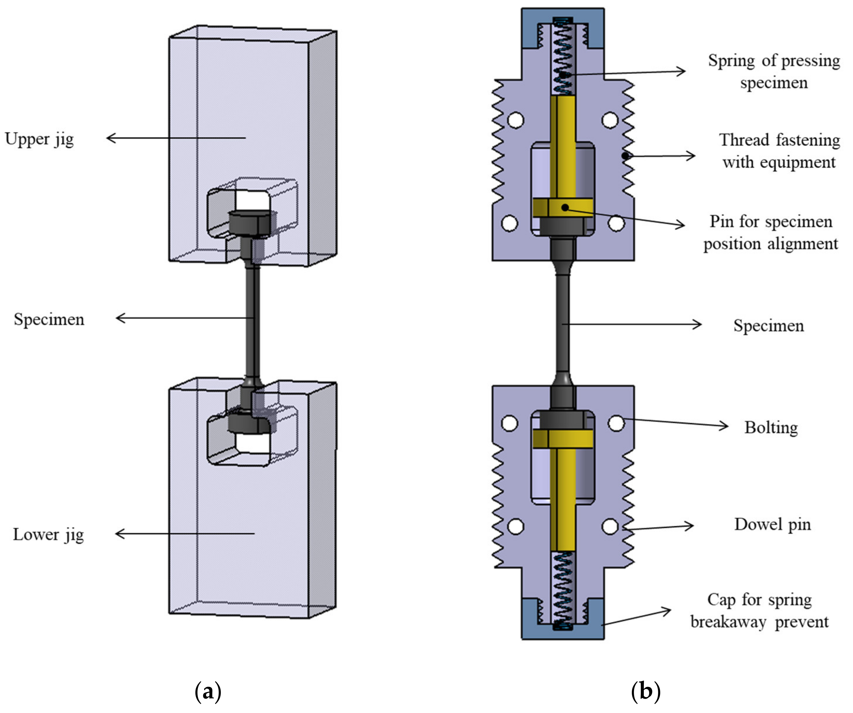
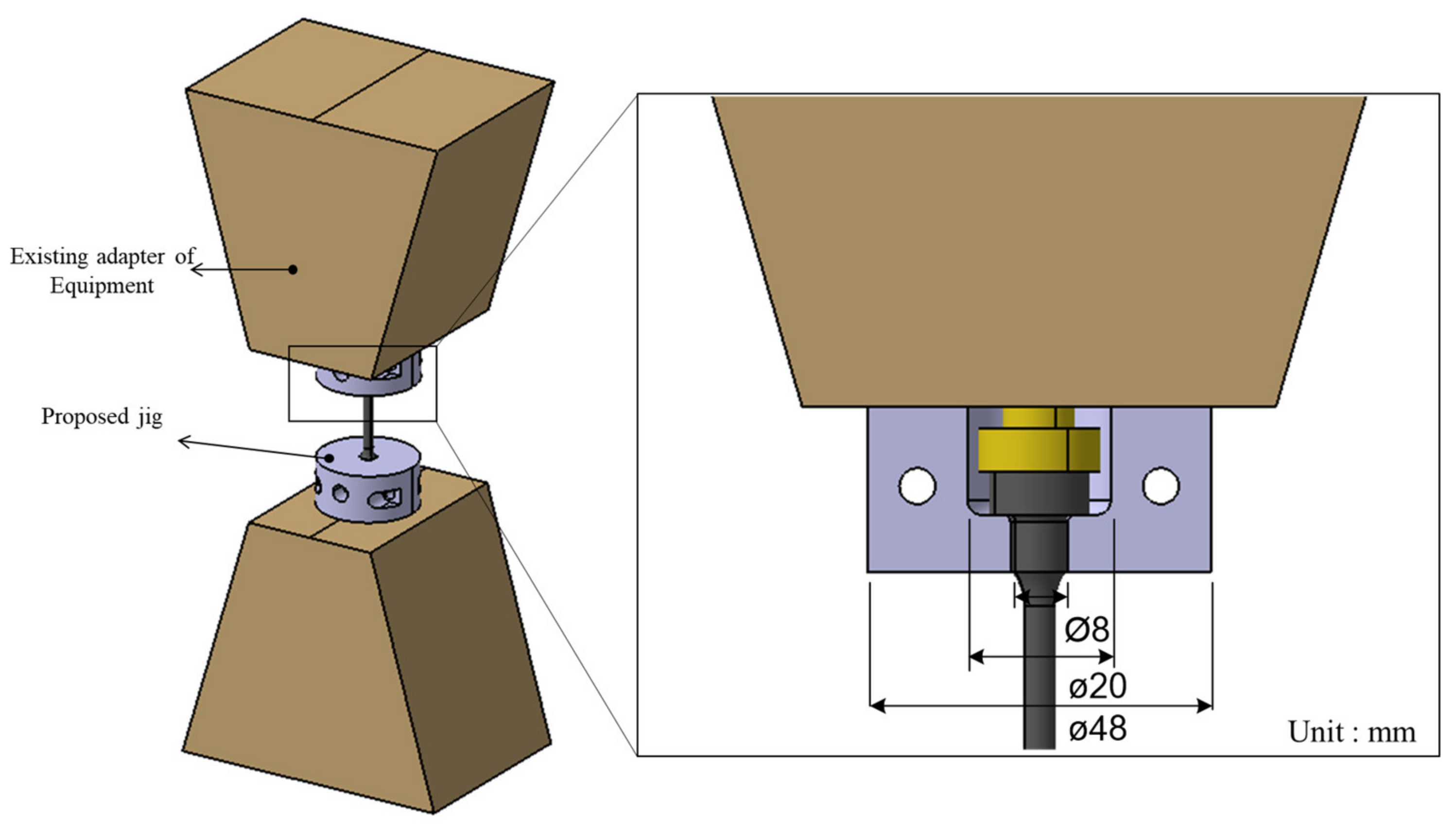
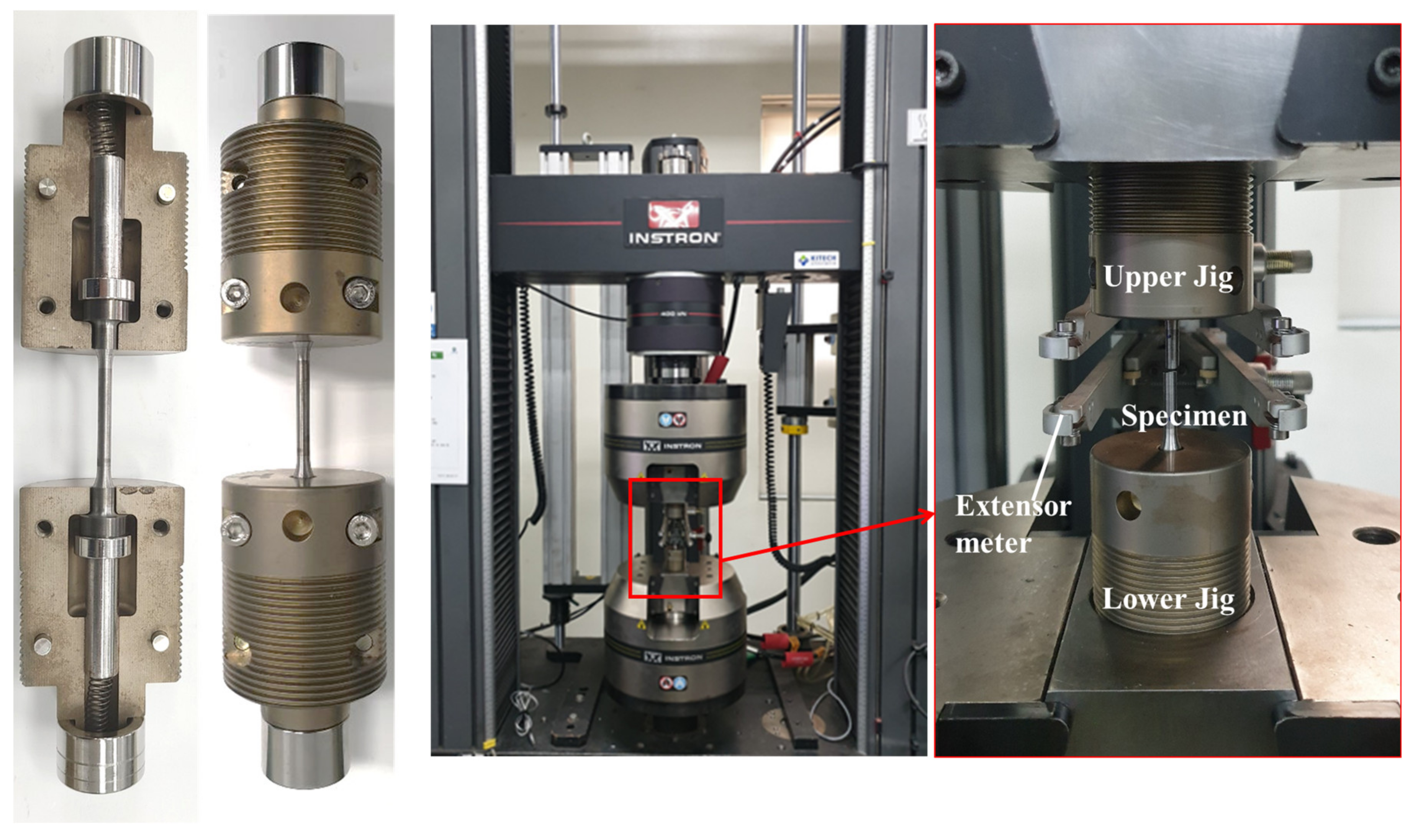
2.1. Design of the High-Strength Tensile Jig

The specimen was designed with a minimal volume, and, then, the tensile jig was designed based on the ASTM standard [23]. The gauge length of the specimen was set to 20 mm. To use a gauge length of 20 mm, it was designed as shown in Figure 1. Isostatic pressure was applied to the specimen during the sintering process. The specimen was to be made in a dumbbell shape, i.e., as close as possible to the final shape. Subsequently, the specimen was manufactured into the final shape by machining.
In general, it is important to fix the x-, y-, and z-axes so that the specimen can receive force along the uniaxial axis during a tensile test. First, the jig was designed using the conventional method, as shown in Figure 2a. This jig had symmetrical deformation, increased the contact area, and minimized size alignment errors.
The proposed jig was designed in a shape surrounding the specimen, as shown in Figure 2b, to further increase the contact area. The proposed jig consists of a body part, a pin for specimen position alignment, and a cap for spring breakaway prevention. The body part was designed in the shape of the body divided in half to facilitate the combination of the specimen, jig, and test equipment. The dowel pin and bolting were designed for accurate coupling and fastening of the separated jig. In addition, the internal space was designed in the body for the movement of the pin for specimen position alignment. A tolerance was given for the exact position between the pin for the specimen position alignment and the body part. The pin for the specimen position alignment was placed on both sides of the specimen to receive uniaxial force. To naturally align the position of the specimen, a spring for pressing the specimen was added. The cap for spring breakaway prevention was designed to press the specimen with constant pressure and to combine the jig. A detailed and combined design with the existing adapter is shown in Figure 3.

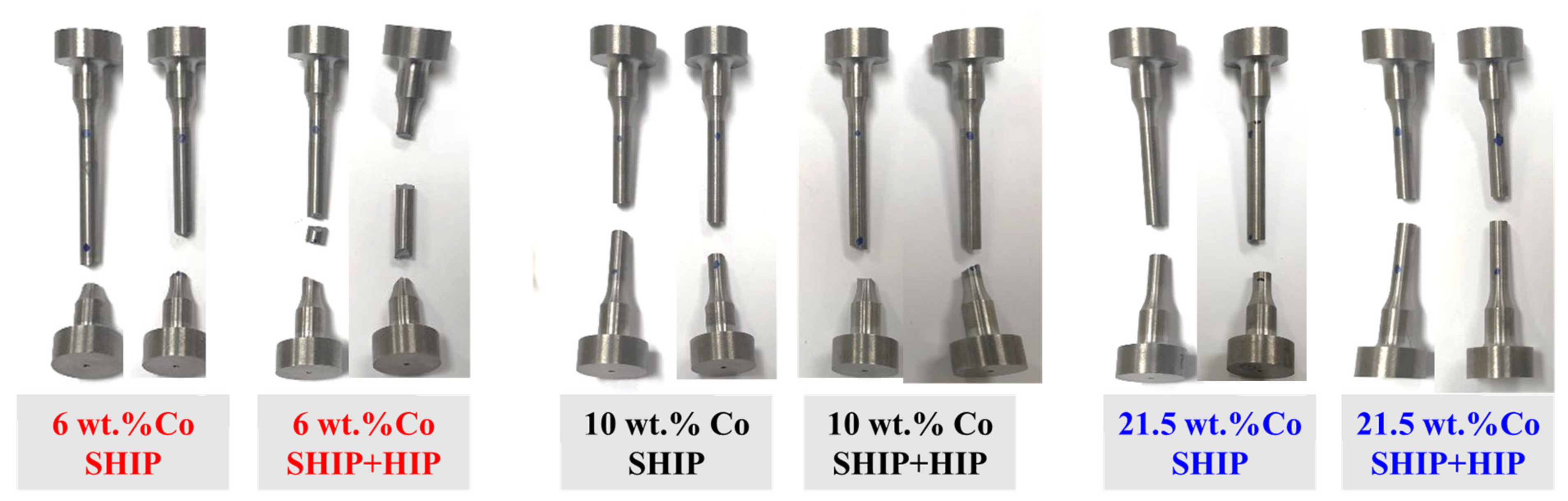
2.2. Experiment and Materials

The chemical composition of WC-Co is shown in Table 1. WC-Co cemented carbides with various Co contents were compared. Although the grain sizes of the three specimens were different, we only focused on the Co content, regardless of the grain size. The Co content was 6 wt.% Co, 10 wt.% Co, and 21.5 wt.% Co. The process conditions for SHIP and HIP are shown in Table 2. The specimens of 6 wt.% Co and 10 wt.% Co were produced at 1410 °C and 6 MPa in the SHIP process and 1310 °C and 98 MPa in the HIP process. The specimen with 21.5 wt.% Co was produced at 1420 °C and 0.9 MPa in the SHIP process and 1310 °C and 98 MPa in the HIP process.
To compare the mechanical properties of WC-Co according to the Co content and processing method, a tensile test was conducted using the proposed jig. The tensile tests were conducted using a universal testing machine (INSTRON, 5988, Norwood, MA, USA), and the preload and test speeds were 5 MPa and 0.01 mm/s, respectively. Three tests were performed to obtain accurate data. To analyze the fracture surface and microstructure evolution of the specimen, field emission scanning electron microscopy (FE-SEM, JEOL, JSM-7900F, Tokyo, Japan) was used. The FE-SEM parameters were as follows: a working distance of 15 mm, an accelerated voltage of 15 kV, a probe current of 10 nA, and a magnification of ×4000. Additionally, to compare the hardness and impact load of the specimen, a hardness tester (Zwick/Roell, ZHU250, Ulm, Germany) and an impact testing machine (INSTRON, MPX-700, Norwood, MA, USA) were used. The impact test was conducted at room temperature, and an instrumentation system was applied [25].

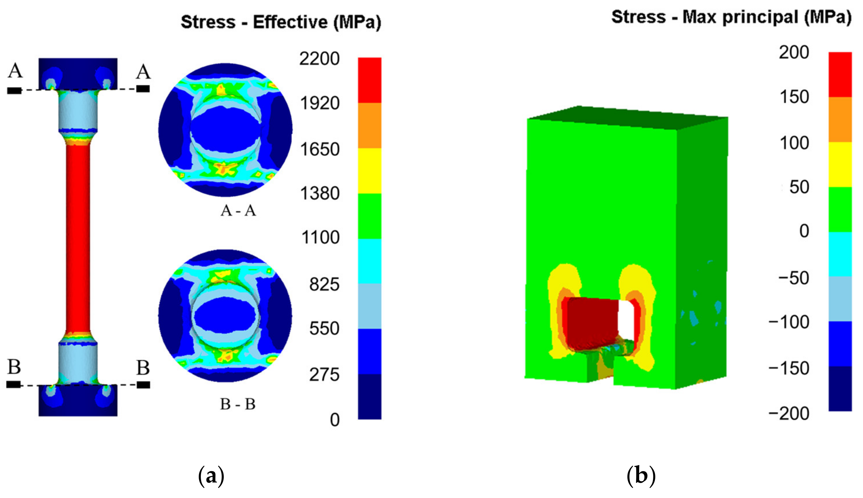
2.3. Finite Element Analysis (FEA)

Deform-3D, a commercial FEA program, was used for the tensile analysis and verification of the proposed jig. The specimen and die properties were WC-15 wt.% Co and AISI D2, which were the basic properties of Deform-3D. As the analysis conditions, the tensile speed was set to 0.01 mm/s, and the shear friction between the specimen and the die was set to the default value of 0.12. Additionally, the results obtained through the tensile test were applied to the die stress analysis, and the results were compared. The applied process is an arbitrary process, as shown in Figure 4. An arbitrary process simulates cold forging with backward extrusion. This process was used to compare the die stress analysis results by applying the material properties with the effect of SHIP and HIP according to the Co content.

3. Results and Discussion

The analysis was carried out under the same conditions with two types of jigs. As a result of the analysis of the previous method, fracture in the gage length section was predicted, and fracture in the neck of the grip section was also predicted, as shown in Figure 5a. It seemed that the stress was concentrated because the contact area between the grip section and the specimen was insufficient. Figure 5b shows the result of the die stress analysis, where the maximum stress was 772 MPa. There was no fracture in the jig, but fatigue fracture may have appeared from repeated use. These results indicate that the probability of fracture decreased due to the dispersion of the stress and the increase in the contact area between the specimen and the jig. The die stress analysis results show a low maximum stress of 167 MPa, as shown in Figure 6b. It was expected that no fractures would appear in the jig. From this result, the proposed jig did not show breakage or fatigue fracture with 0.21 times the stress of the conventional method.
As shown in Figure 7, the proposed jig was manufactured based on the designed dimensions and attached to a universal testing machine. The tensile test confirmed that fracture occurred only in the gage length section, and no fracture occurred in the grip section and jig, as shown in Figure 8. The results obtained from the experiments are shown in Figure 9. In the case of SHIP, the higher the Co content, the lower the tensile strength and Young’s modulus and the higher the strain rate. However, different aspects were revealed depending on the results of HIP after SHIP. Regardless of the Co content, the tensile strength increased in the order 10 wt.% Co, 6 wt.% Co, and 21.5 wt.% Co, and the elongation increased in the order 21.5 wt.% Co, 10 wt.% Co, and 6 wt.% Co. In the case of 10 wt.% Co, the HIP after SHIP process showed improved properties in terms of tensile strength and elongation. WC-Co is very brittle, and necking did not appear in repeated experiments. In the case of 6 wt.% Co, the maximum tensile strength was expected based on the slope value of the elastic section, but elongation was too short to result in a higher value owing to the characteristics of the brittle materials. Therefore, the tensile strength of 10 wt.% Co was higher than that of 6 wt.% Co, which had a relatively high elongation. The detailed results in Table 3 show that HIP after SHIP improves Young’s modulus. The results of the tensile test confirmed that various results were related to the Co content and HIP treatment.
The results of the hardness and impact tests had an inverse relationship, as shown in Figure 10. The hardness test results were similar to the tensile test results, and there was a proportional relationship with Young’s modulus. When compared with the hardness value of conventionally prepared WC-Co, it was confirmed that the hardness value was high in the case of 6 wt.% Co and 10 wt.% Co [5,26]. The 21.5 wt.% Co appears to have a low value due to the difference in Co content, but exhibits almost similar hardness values. In the impact test, the higher the Co content, the higher is the impact energy. The energy of the 6 wt.% Co and 21.5 wt.% Co was increased by HIP after SHIP, but that of the 10 wt.% Co was decreased. From these results, it is clear that when the Co content is high, the hardness decreases and the impact energy increases. HIP after SHIP improved the mechanical properties, but there was no significant change.
Figure 11 shows the fracture surfaces of each tensile specimen. All specimens showed typical brittle fractures, such as river patterns. As the Co content increased, Co was attached to the surface of the WC, and the edges of WC were smooth. This is because of the growth of grains and coalescence [3]. Compared to the SHIP specimens, the HIP-treated specimens had coarse grains, and Co was stuck to the surface of the WC. From this phenomenon, the strength was higher in the impact test results.
Figure 12 shows the fracture surface of each impact test specimen. All specimens exhibited typical brittle fractures. The SHIP and HIP-treated specimens showed similar results to the tensile fracture surfaces. The 6 wt.% Co showed intergranular fracture as a whole, and there was no difference between the beginning and the end of the fracture. For the 10 wt.% Co, a slight transgranular cleavage fracture in the surface appeared, while most of the intergranular fracture was observed in the overall specimen. The impact energy of HIP after SHIP decreased in the impact tests due to the pores appearing in area A in the surface (Figure 12). There was no difference between the beginning and the end. In the 21.5 wt.% Co, a cleavage fracture surface was mainly visible, and there were many transgranular fractures. Furthermore, secondary cracking was clearly observed in the circled part. Usually, an intergranular fracture breaks through the grain boundary, so that it absorbs less energy than a transgranular fracture under yield stress [27,28]. In the impact test results, it was judged that the high impact energy of 21.5 wt.% Co caused a substantial transgranular fracture.
Figure 13 shows the microstructure of the polished WC-Co cemented carbide with the distribution of WC grains. The WC grains appeared to be homogeneously distributed. The higher the Co content, the coarser the WC of the grains and gaps. In general, the hardness increased as the grains became finer. However, in the case of coarse grains, the crack required more energy to bypass or pass through [29]. Therefore, the formation of small cracks that may exist at the WC-Co interface could be effectively prevented. From these results, it can be concluded that the higher the Co content, the higher the elongation and impact energy.
As a result of applying the die stress analysis based on the results obtained from the tensile test, the stress values applied to the die were all the same, so there was a difference in the displacement value of the die according to the stress. The smaller the displacement value, the less the deformation of the die; therefore, this method is considered to be the most suitable for a cold-forging die. Figure 14 shows the results of the die stress analysis and compares Young’s modulus and displacement. As a result of the analysis, the specimen with a lower Co content and HIP exhibited a low deformation. In the case of 6 wt.% Co, the displacement of the punch and die was reduced from 0.143 mm and 0.047 mm to 0.142 mm and 0.048 mm, respectively, by the HIP treatment. The 10 wt.% Co showed little change: the displacement of the punch and die were changed from 0.16 mm and 0.055 mm to 0.16 mm and 0.052 mm, respectively, by the HIP treatment. Both 6 wt.% Co and 10 wt.% Co had no significant change regardless of HIP. In the case of 21.5 wt.% Co, the displacement of the punch and die was reduced from 0.202 mm and 0.067 mm to 0.176 mm and 0.058 mm, respectively, by the HIP treatment. It was confirmed that the displacement increased when Young’s modulus was lowered, and the displacement was decreased by the HIP treatment. It seems that the density and bonding strength increased owing to the HIP treatment. From this result, 6 wt.% Co might be the most suitable material for a cold-forging die, regardless of HIP treatment. The life of the cold die might vary depending on the stress ring and the design method. For improving the quality and expendability, further studies may use other parameters, such as pressure variations, with diffusion bonding during sintering [30].

4. Conclusions

In this study, a jig was proposed to obtain the tensile strength of WC-Co, a high-hardness material, and the results of the Co content, SHIP, and HIP treatment were compared and analyzed. The results of this study are as follows:
  • A jig for high-strength materials was proposed. The jig can be easily attached and detached to a universal testing machine that is widely used and does not exceed the standard range. Through the FEA results, the validity of the proposed jig could be obtained, and a jig with a stress 0.21 times lower than that in a previous study could be designed;
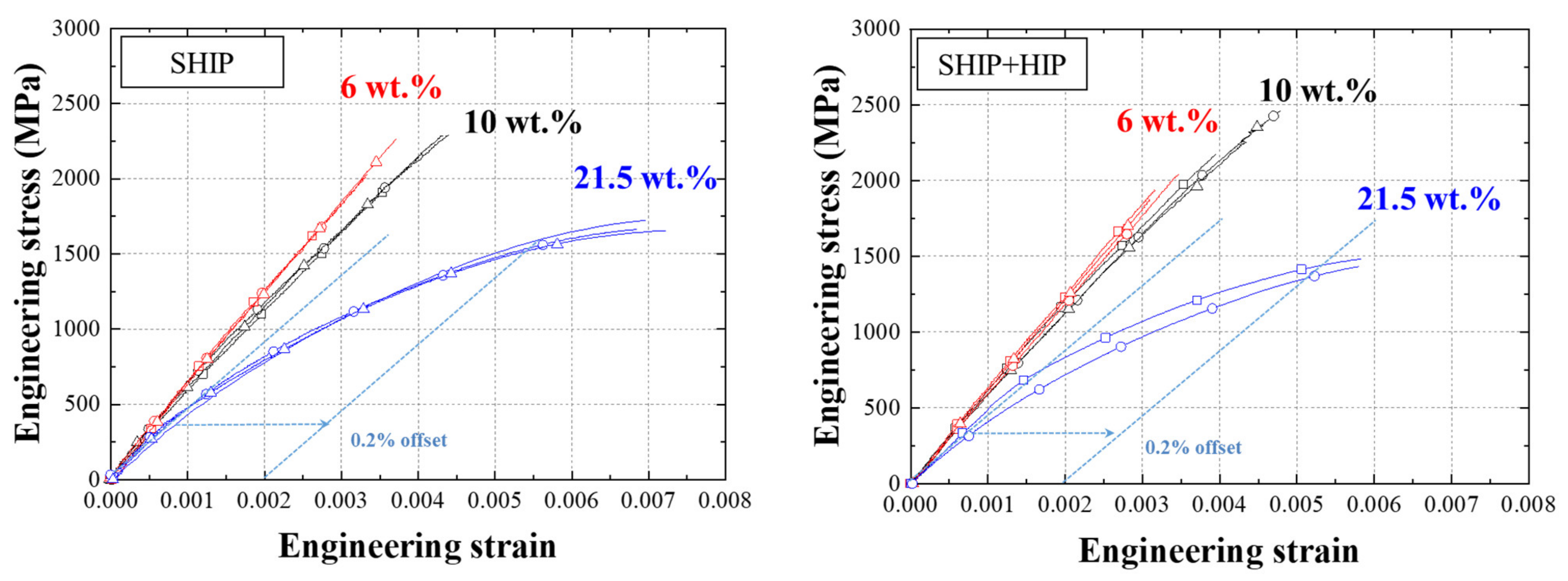
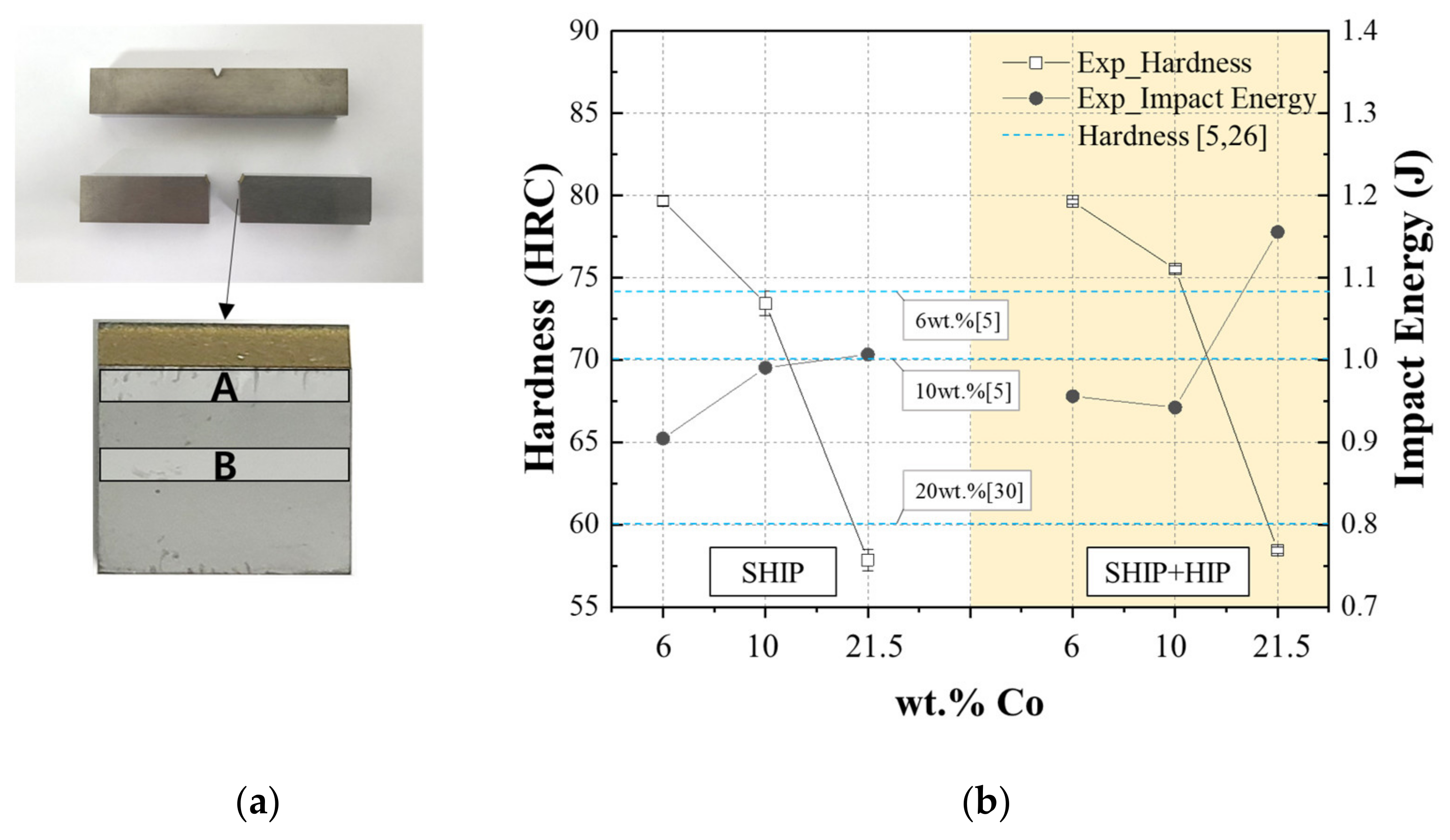
  • As a result of the tensile test with the proposed jig and specimen, the lower the Co content, the higher the modulus and tensile strength and the lower the elongation. It was confirmed that Young’s modulus was improved by HIP treatment. Similar to the tensile test results, the additional hardness test results showed an increasing tensile strength in the order 6 wt.% Co, 10 wt.% Co, and 21.5 wt.% Co. However, as a result of the impact test, 21.5 wt.% Co, which had a low tensile strength but a high strain, had the highest impact energy, and 6 wt.% Co and 10 wt.% Co showed similar results;
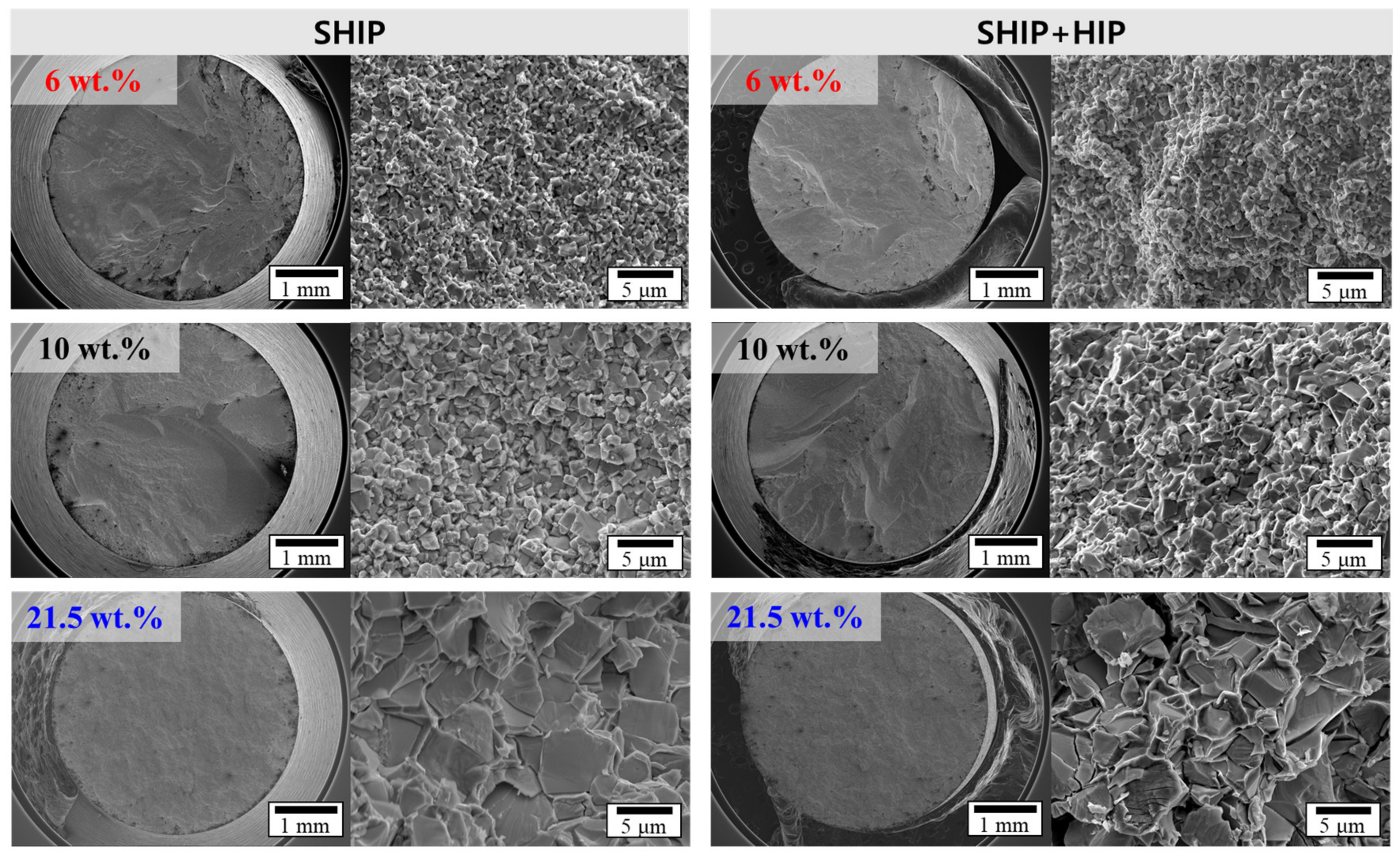
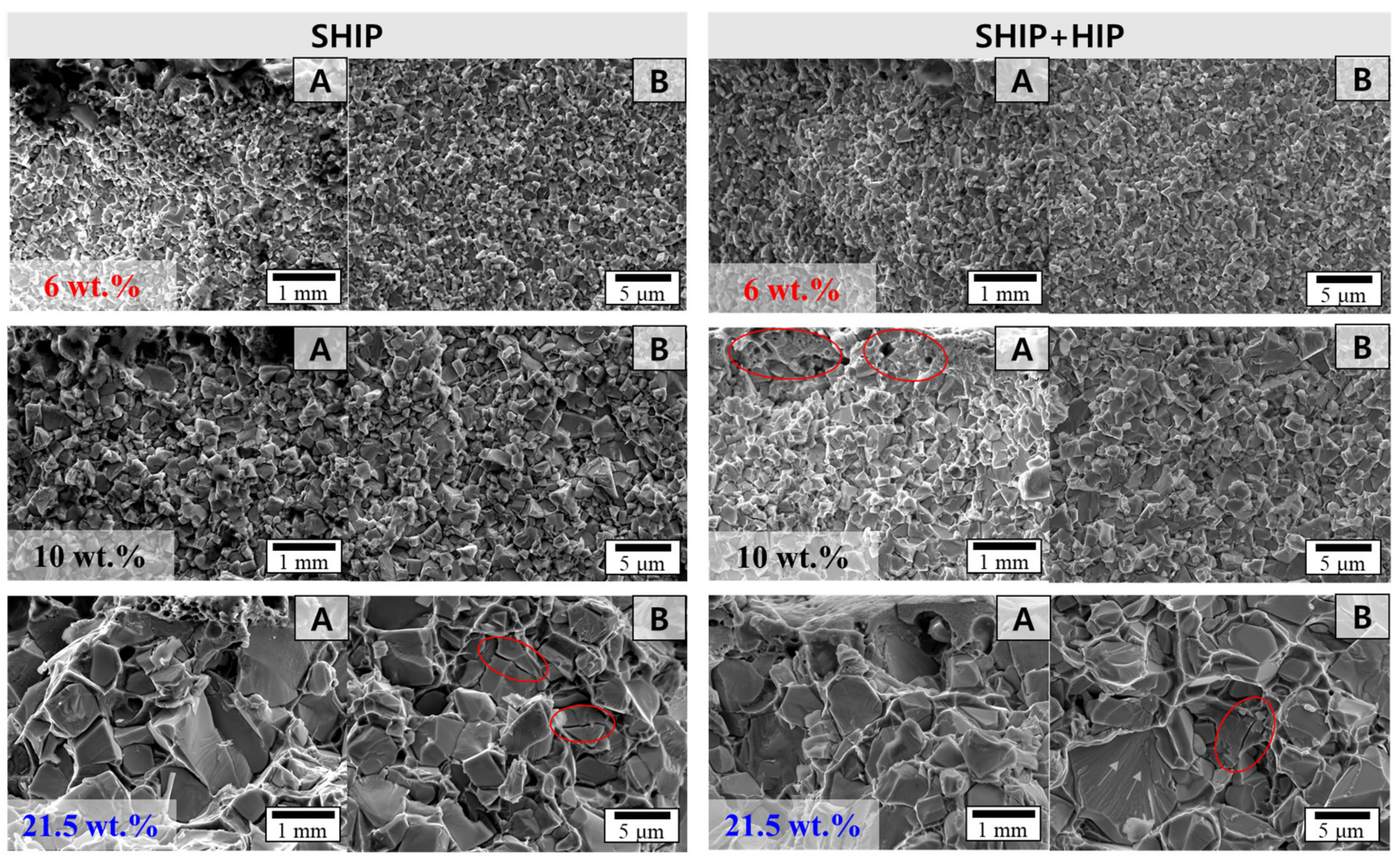
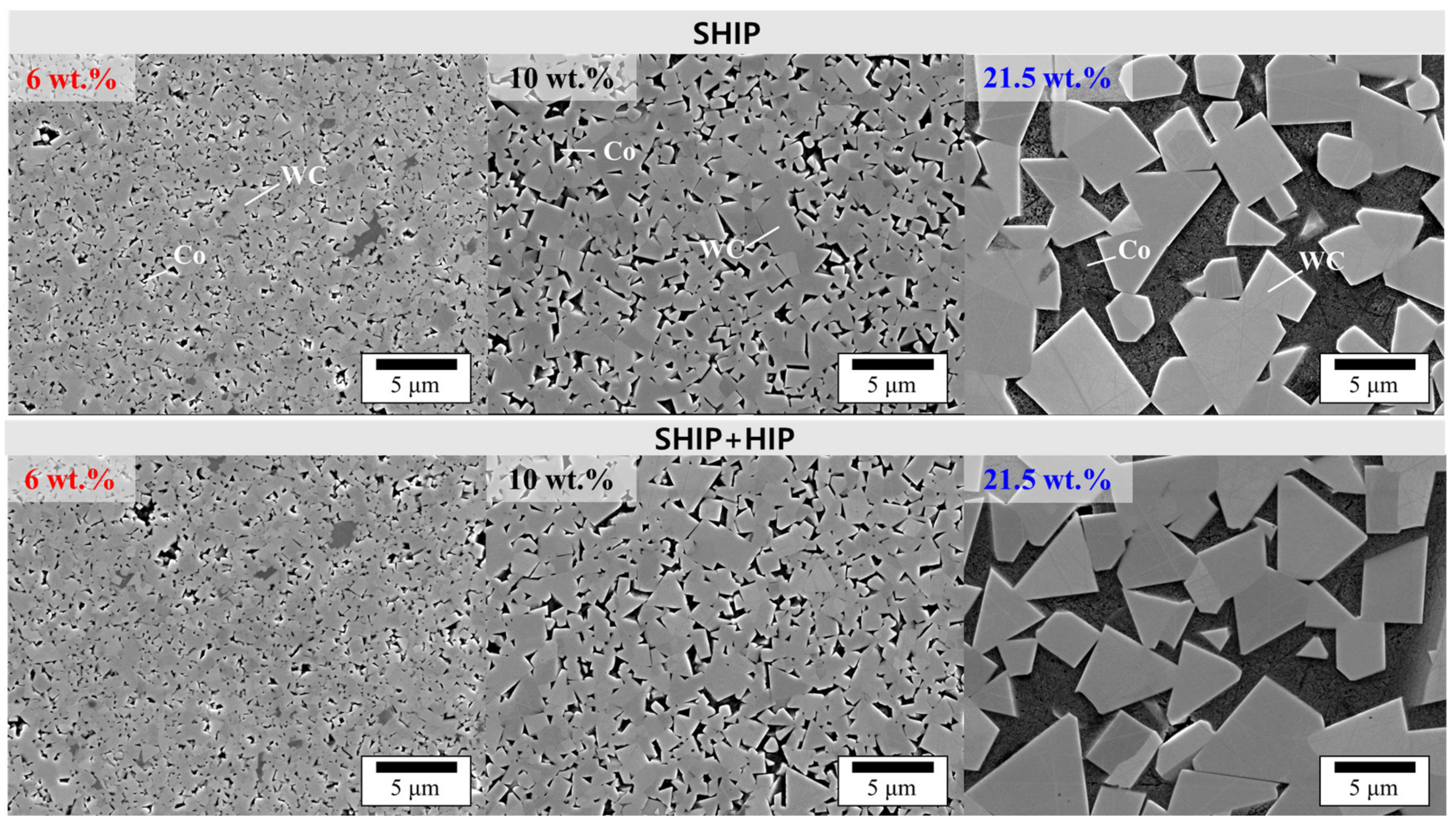
  • As a result of the microstructure, brittle fracture appeared in all specimens, and the grains were homogeneously distributed. As the Co content increased, Co was attached to the surface of WC, and the WC grains and gaps became coarse and wide;
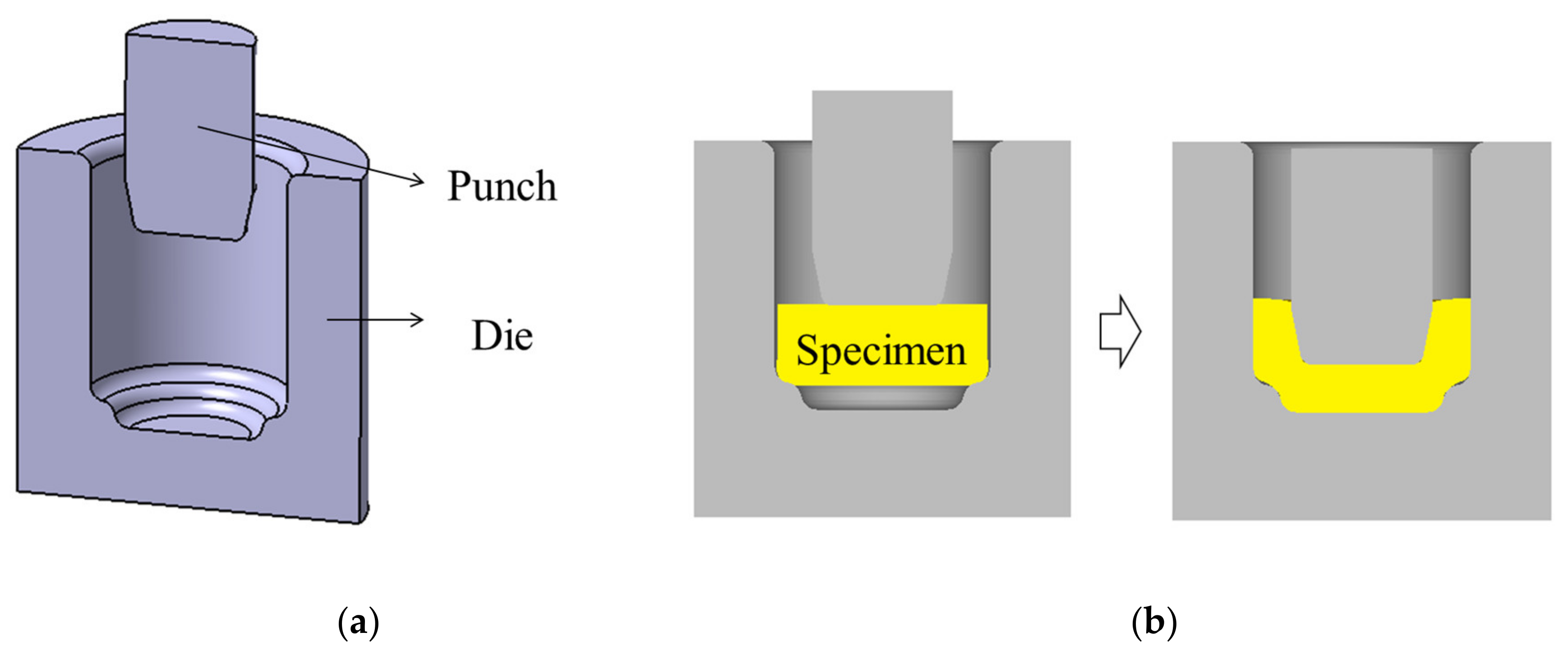
  • Die stress analysis was performed using 6 wt.% Co, which had the highest tensile strength, and the results showed a low displacement, regardless of HIP treatment, which might be suitable for this process.

5. Patents

The application number is 10-2019-0161505 in Korea.

Author Contributions

Conceptualization, A.-R.J. and S.-K.H.; methodology, A.-R.J. and S.-K.H.; software, A.-R.J., J.-S.A., and M.-S.J.; data curation, A.-R.J. and S.-H.K.; writing—original draft preparation, A.-R.J. and S.-K.H.; writing—review and editing, S.-K.H.; validation and investigation, Y.-H.M. All authors have read and agreed to the published version of the manuscript.

Funding

This research was funded by Korea Institute of Industrial Technology as “Process Data Visualization of Ppuri Industry Supporting Project” grant number KITECH EM-21-0013.

Institutional Review Board Statement

Not applicable.

Informed Consent Statement

Not applicable.

Data Availability Statement

No new data were created or analyzed in this study. Data sharing is not applicable to this article.

Acknowledgments

This work was supported by Sinseng Industrial Co., Ltd., Korea.

Conflicts of Interest

The authors declare no conflict of interest.

References

  1. García, J.; Ciprés, V.C.; Blomqvist, A.; Kaplan, B. Cemented carbide microstructures: A review. Int. J. Refract. Met. Hard. Mater. 2019, 80, 40–68. [Google Scholar] [CrossRef]
  2. Ghasali, E.; Ebadzadeh, T.; Alizadeh, M.; Razavi, M. Spark plasma sintering of WC-based cermets/titanium and vanadium added composites: A comparative study on the microstructure and mechanical properties. Ceram. Int. 2018, 44, 10646–10656. [Google Scholar] [CrossRef]
  3. Musa, M.Š.; Sakoman, M.; Ćorić, D.; Aleksandrov Fabijanić, T. Exploitation and wear properties of nanostructured WC-Co tool modified with plasma-assisted chemical vapor deposition TiBN Coating. Metals 2021, 11, 333. [Google Scholar] [CrossRef]
  4. Liu, K.; Wang, Z.; Yin, Z.; Cao, L.; Yuan, J. Effect of Co content on microstructure and mechanical properties of ultrafine grained WC-Co cemented carbide sintered by spark plasma sintering. Ceram. Int. 2018, 44, 18711–18718. [Google Scholar] [CrossRef]
  5. He, M.; Wang, J.; He, R.; Yang, H.; Rua, J. Effect of cobalt content on the microstructure and mechanical properties of coarse-grained WC-Co cemented carbides fabricated from chemically coated composite powder. J. Alloy. Compd. 2018, 766, 556–563. [Google Scholar] [CrossRef]
  6. Breval, E.; Cheng, J.P.; Agrawal, D.K.; Agrawal, P.; Dennis, M.; Roy, R.; Papworth, A.J. Comparison between microwave and conventional sintering of WC/Co composites. Mater. Sci. Eng. A 2005, 391, 285–295. [Google Scholar] [CrossRef]
  7. Gurland, J.; Bardzil, P. Relation of Strength, Composition, and Grain Size of Sintered WC-Co Alloys. J. Miner. Met. Mater. Soc. 1955, 7, 311–315. [Google Scholar] [CrossRef]
  8. Atkinson, H.V.; Davies, S. Fundamental aspects of hot isostatic pressing: An overview. Metall. Mater. Trans. A 2000, 31A, 2981–3000. [Google Scholar] [CrossRef]
  9. Swinkels, F.B.; Wilkinson, D.S.; Arzt, E.; Ashby, M.F. Mechanisms of hot-isostatic pressing. Acta Metall. 1983, 31, 1829–1840. [Google Scholar] [CrossRef] [Green Version]
  10. Tian, F.; Chen, C.; Liu, Y.; Liu, Q.; Ivanov, M.; Wang, Q.; Jiang, N.; Chen, H.; Yang, Z.; Xie, T.; et al. Fabrication of Nd:YAG transparent ceramics from co-precipitated powders by vacuum pre-sintering and HIP post-treatment. Opt. Mater. 2020, 101, 109728. [Google Scholar] [CrossRef]
  11. Soria, T.; Lopez, B.; Lozada, L.; Moseley, S.; Alveen, P.; Elsen, M.; Müller-Grunz, A.; Magin, M.; Useldinger, R.; Sánchez, J.M. An investigation into the effects of HIP after sintering of WC-ZrC-Co-Cr3C2 cemented carbides. Int. J. Refract. Met. Hard. Mater. 2020, 87, 105164. [Google Scholar] [CrossRef]
  12. Ustundag, M.; Varol, R. Comparison of a commercial powder and a powder produced from Ti–6Al–4V chips and their effects on compacts sintered by the sinter-HIP method. Int. J. Miner. Metall. Mater. 2019, 26, 878–888. [Google Scholar] [CrossRef]
  13. Xiong, Z.; Shao, G.; Shi, X.; Duan, X.; Yan, L. Ultrafine hard metals prepared by WC–10 wt.%Co composite powder. Int. J. Refract. Met. Hard. Mater. 2008, 26, 242–250. [Google Scholar] [CrossRef]
  14. Wei, C.; Song, X.; Zhao, S.; Zhang, L.; Liu, W. In-situ synthesis of WC–Co composite powder and densification by sinter-HIP. Int. J. Refract. Met. Hard. Mater. 2010, 28, 567–571. [Google Scholar] [CrossRef]
  15. Ko, D.C.; Kim, B.M. The prediction of central burst defects in extrusion and wire drawing. J. Mater. Process. Technol. 2000, 102, 19–24. [Google Scholar] [CrossRef]
  16. Lee, K.S.; Kim, G.Y.; Ahn, Y.S. Study on the Optimum Design of the Insert Ring and Shrunk Ring of the Cold Forging Die for an Automotive Wheel Nut. Trans. Mater. Process 2018, 27, 165–170. [Google Scholar]
  17. Yang, T.S.; Hwang, N.C.; Chang, S.Y. The prediction of maximum forging load and effective stress for different material of bevel gear forging. J. Mech. Sci. Technol. 2007, 21, 1566–1572. [Google Scholar] [CrossRef]
  18. Choi, J.S.; Lee, H.C.; Im, Y.T. A study on chevron crack formation and evolution in a cold extrusion. J. Mech. Sci. Technol. 2010, 24, 1885–1890. [Google Scholar] [CrossRef]
  19. Weibull, W. A Statistical Theory of the Strength of Materials; Generalstabens litografiska anstalts förlag: Stockholm, Sweden, 1939. [Google Scholar]
  20. General Carbide Corporation. Designer’s Guide to Tungsten Carbide. 2010. Available online: http://www.generalcarbide.com (accessed on 24 April 2021).
  21. ISO 3327:2009. Hardmetals–Determination of Transverse Rupture Strength; International Organization for Standardization: Vernier, Switzerland, 2009. [Google Scholar]
  22. ASTM B406-96. Standard Test Method for Transverse Rupture Strength of Cemented Carbides; ASTM International: West Conshohocken, PA, USA, 2015. [Google Scholar]
  23. ASTM E8/E8M. Standard Test Methods for Tension Testing of Metallic Materials; ASTM International: West Conshohocken, PA, USA, 2013. [Google Scholar]
  24. Kwon, I.W.; Seo, Y.H.; Jung, K.H. Development of Uniaxial Tensile Test Method to Evaluate Material Property of Tungsten Carbide-Cobalt Alloys for Cold Forging Dies. Trans. Mater. Process. 2018, 27, 370–378. [Google Scholar]
  25. ASTM E23-18. Standard Test Methods for Notched Bar Impact Testing of Metallic Materials; ASTM International: West Conshohocken, PA, USA, 2018. [Google Scholar]
  26. Kress, T.; Meinhard, D.; Bernthaler, T.; Schneider, G. Hardness of WC-Co hard metals: Preparation, quantitative microstructure analysis, structure-property relationship and modelling. Int. J. Refract. Met. Hard. Mater. 2018, 75, 278–293. [Google Scholar] [CrossRef]
  27. William, C.; David, R. Solution Manual for Materials Science and Engineering, 9th ed.; Wiley: Hoboken, NJ, USA, 2017. [Google Scholar]
  28. Chao, Y.; Jianming, R.; Yong, D.; Jianzhan, L.; Yingbiao, P.; Kai, L. Effects of Cr3C2, VC, and TaC on Microstructure, WC Morphology and Mechanical Properties of Ultrafine WC–10 wt. % Co Cemented Carbides. Metals 2020, 10, 1211. [Google Scholar]
  29. De Macedo, H.R.; da Silva, A.G.P.; de Melo, D.M.A. The spreading of cobalt, nickel and iron on tungsten carbide and the first stage of hard metal sintering. Mater. Lett. 2003, 57, 3924–3932. [Google Scholar] [CrossRef]
  30. AlHazaa, A.; Haneklaus, N.; Almutairi, Z. Impulse Pressure-Assisted Diffusion Bonding (IPADB): Review and Outlook. Metals 2021, 11, 323. [Google Scholar] [CrossRef]
Figure 1. Dimensions of specimen for high-strength tensile tests.
Metals 11 00884 g001
Figure 2. Schematic of a jig for high-strength tensile tests: (a) conventional jig and (b) proposed jig.
Metals 11 00884 g002
Figure 3. Dimensions of the proposed jig for high-strength tensile tests combined with the existing adapter of the equipment.
Metals 11 00884 g003
Figure 4. (a) Schematic of die and punch, and (b) arbitrary process for die stress analysis.
Metals 11 00884 g004
Figure 5. Result of jig analysis of conventional method: (a) effective stress of specimen and (b) maximum principal stress of die.
Metals 11 00884 g005
Figure 6. Result of the jig analysis of the proposed method: (a) effective stress of specimen and (b) maximum principal stress of die.
Metals 11 00884 g006
Figure 7. Manufactured jig and experimental setup for high-strength tensile tests.
Metals 11 00884 g007
Figure 8. View of the tensile specimen using the proposed jig.
Metals 11 00884 g008
Figure 9. Comparison of the tensile test result of WC-Co according to the Co content and HIP treatment.
Metals 11 00884 g009
Figure 10. (a) Shape of the impact test specimen and (b) result of Rockwell hardness test and impact test.
Metals 11 00884 g010
Figure 11. Comparison of SEM micrograph maps of WC-Co according to the Co content and HIP treatment.
Metals 11 00884 g011
Figure 12. Comparison of SEM micrograph maps of impact specimens.
Metals 11 00884 g012
Figure 13. Comparison of SEM micrograph maps of WC-Co according to the Co content and HIP treatment.
Metals 11 00884 g013
Figure 14. (a) Results of die stress analysis distribution and (b) comparison of young’s modulus and displacement according to Co content and Hip treatment.
Metals 11 00884 g014
Table 1. Chemical composition of WC-Co according to the Co content.
Chemical Composition (wt.%)
CoWCFeTaNb
686.835.810.000.700.66
1084.485.520.000.000.00
21.572.754.751.000.000.00
Table 2. Process conditions of SHIP and HIP.
wt.% CoPowder Size (μm)SHIPHIP
Maximum Temperature (°C)Maximum Pressure (MPa)Maximum Temperature (°C)Maximum Pressure (MPa)
60.6–0.914106131098
101.4–2.014106131098
21.55.0–7.914200.9131098
Table 3. Material properties of WC-Co according to the Co content.
Processwt.% CoYoung’s Modulus (GPa)Ultimate Tensile Strength (MPa)
SHIP66152102
105322243
21.54341680
SHIP + HIP66181952
105532335
21.54971456
Publisher’s Note: MDPI stays neutral with regard to jurisdictional claims in published maps and institutional affiliations.

