
Application of Viscous Damper and Laminated Rubber Bearing Pads for Bridges in Seismic Regions


Abstract
:1. Introduction
2. Application of VD-LRBP System for Highway Bridges
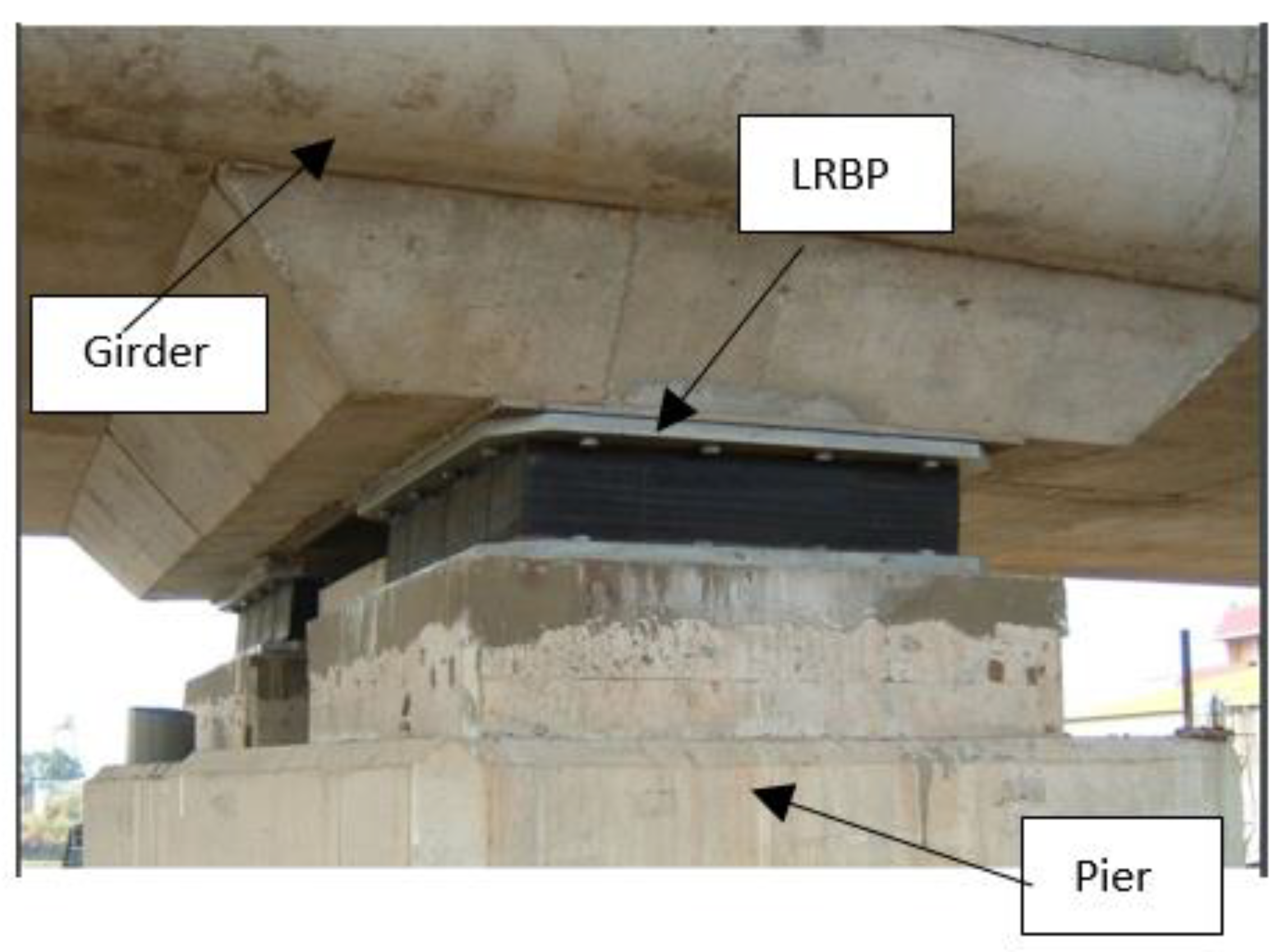
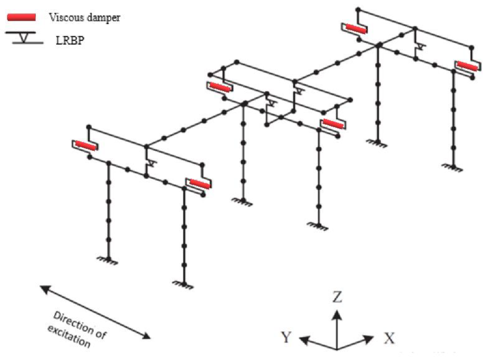
- LRBPs are placed between the girders and piers with no restraint of horizontal motion other than friction. Therefore, they only carry out the gravity load and transmit it to the substructures. On the other hand, dampers are not participating in transferring the gravity loads. They dissipate earthquake energy and provide the bridge with lateral stiffness. Accordingly, the increased lateral stiffness of the bridge reduces the relative displacement between piers and girders;
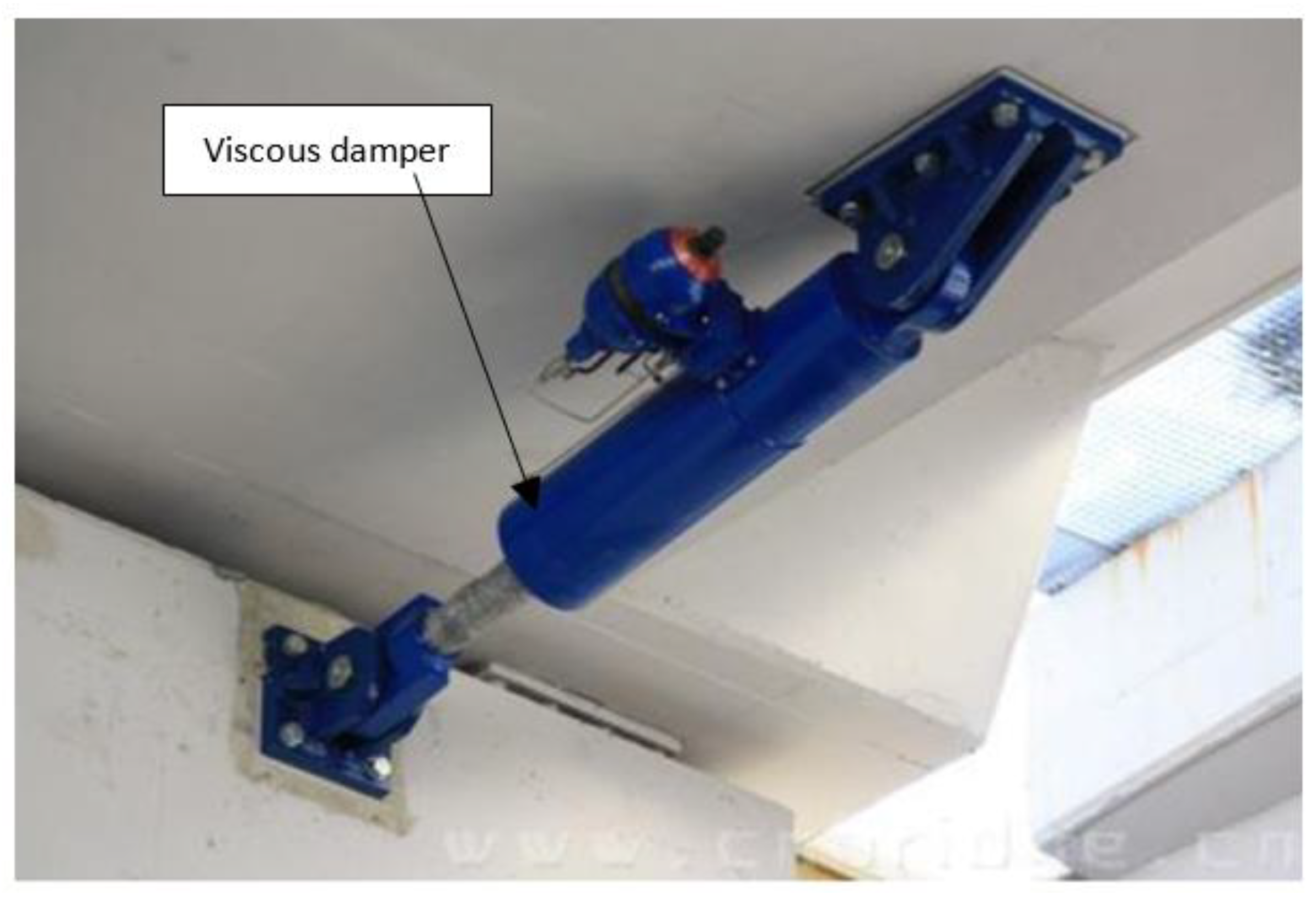
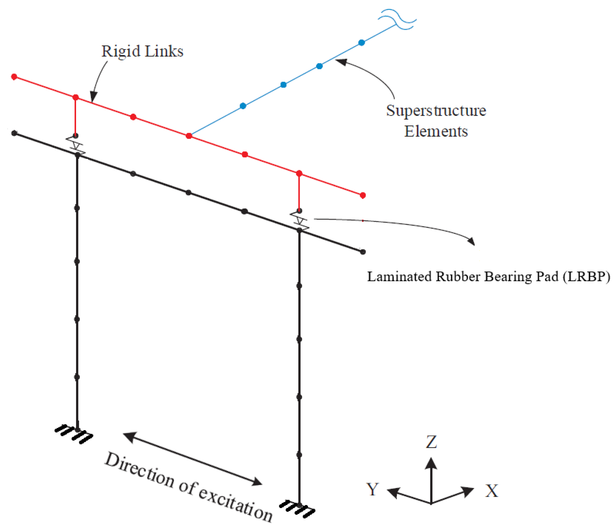
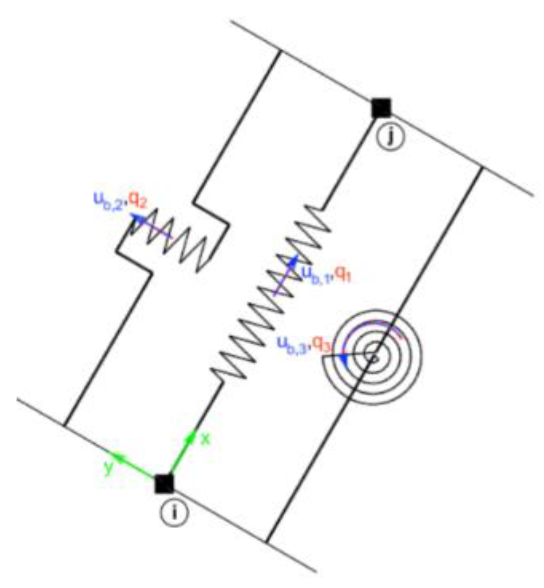
- In the proposed configuration, the dampers are connecting the side of the girder to the top of the pier cap. As such, dampers and LRBPs perform as a parallel system, and their displacements are equal. The system acts in series with the piers. This distinction is required for accurate modeling in finite element analysis.
Viscous Damper
3. Finite Element Analysis
3.1. Validation of the Finite Element Model
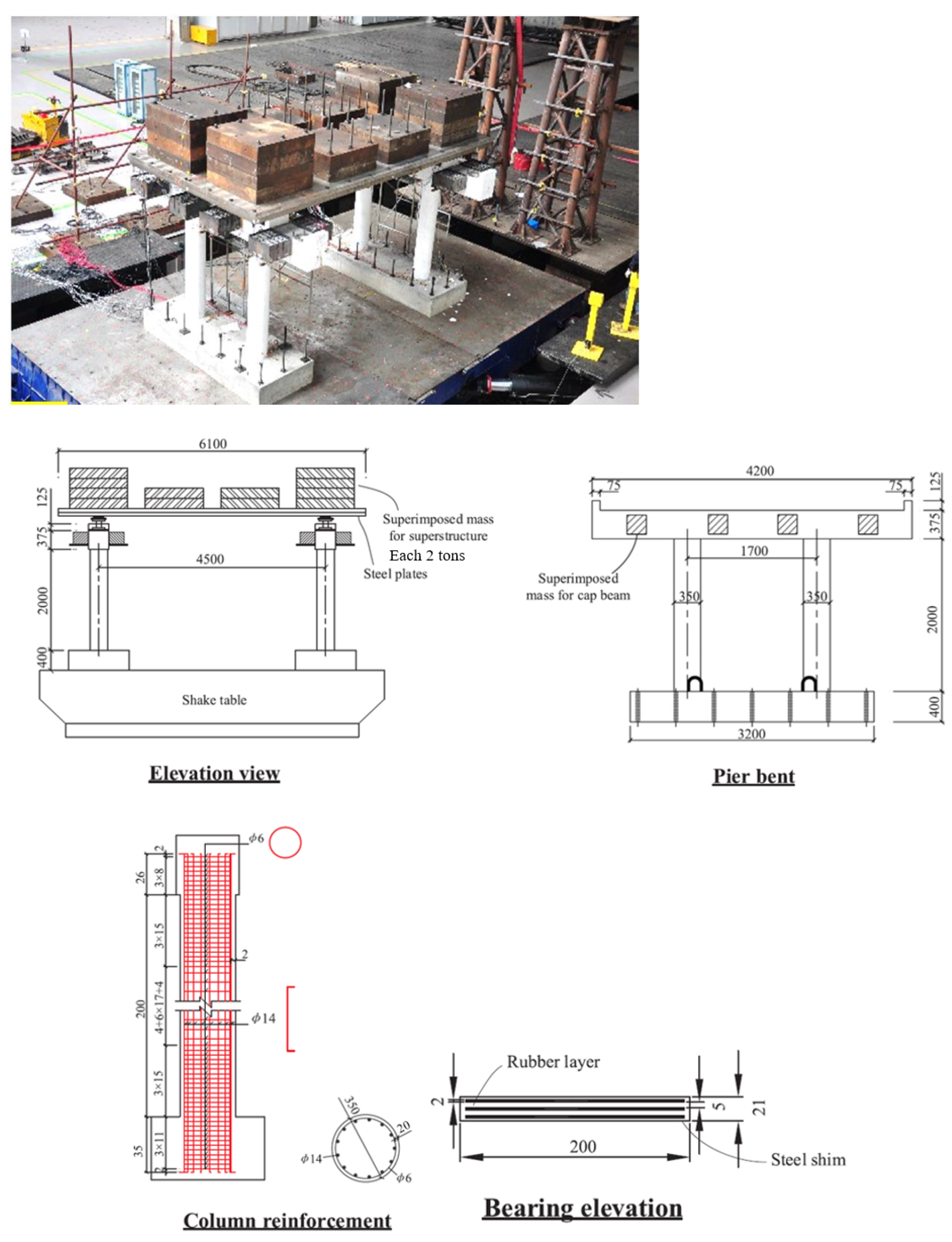
3.1.1. Bridge Model
3.1.2. Beam
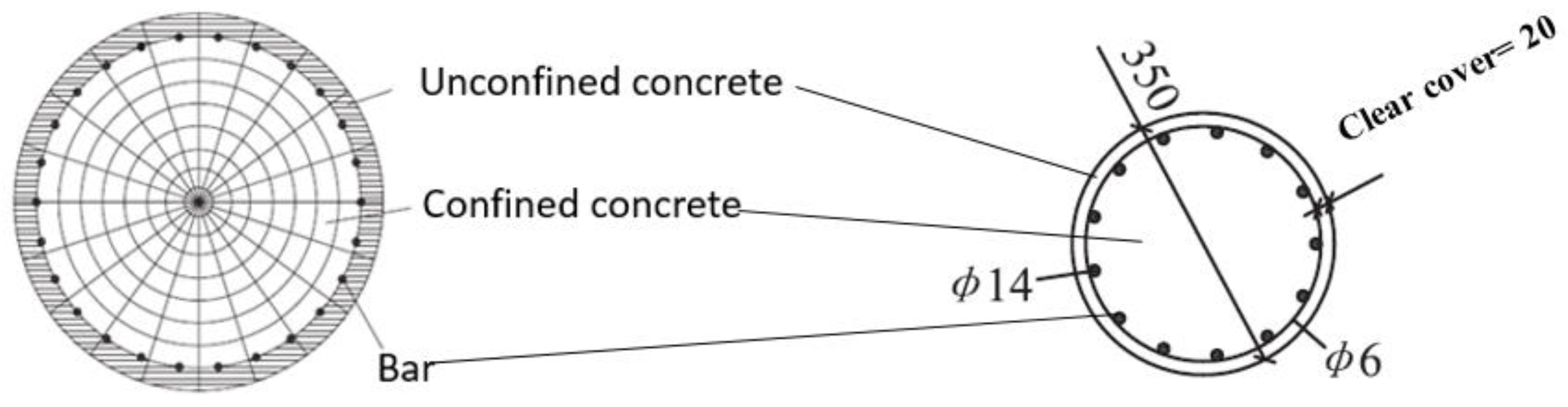
3.1.3. Columns
3.1.4. Laminated Rubber Bearing Pad (LRBP)
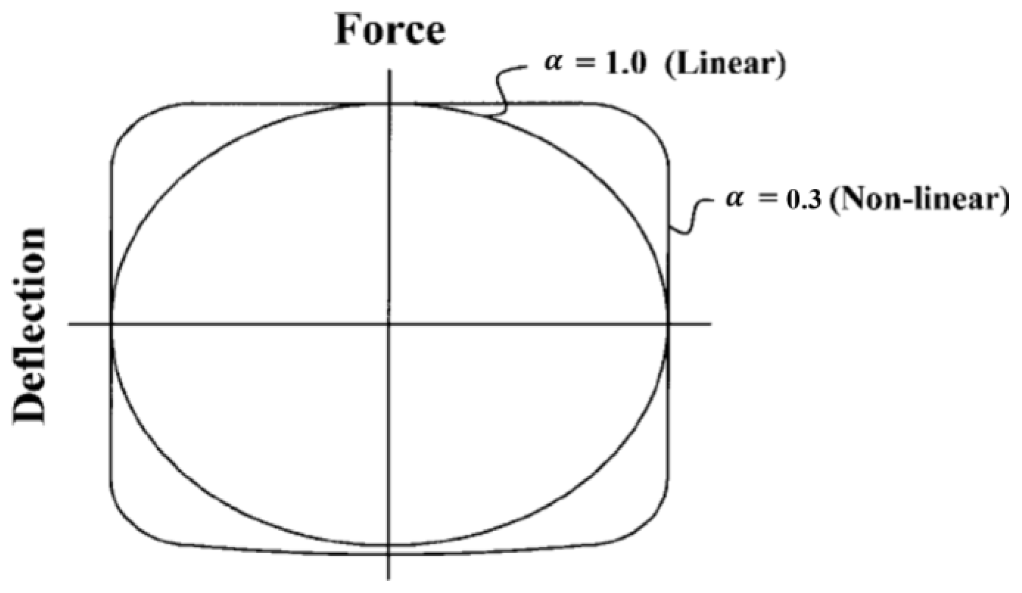
3.1.5. Viscous Damper
3.1.6. Verification of Finite Element Model
3.2. Analysis for VD-LRBP System Performance
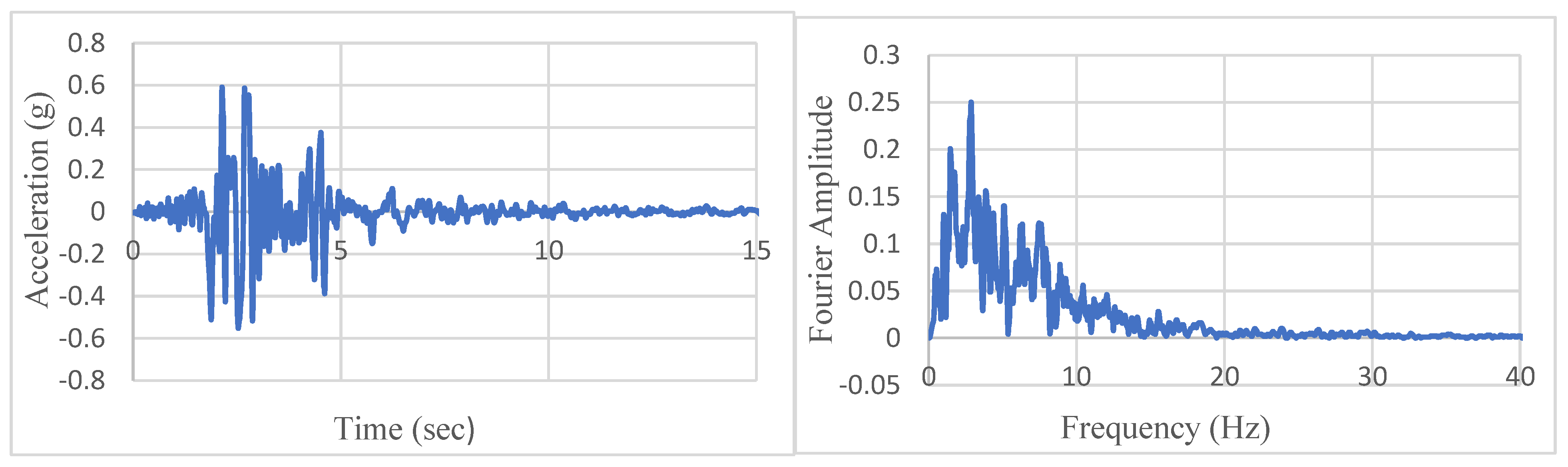
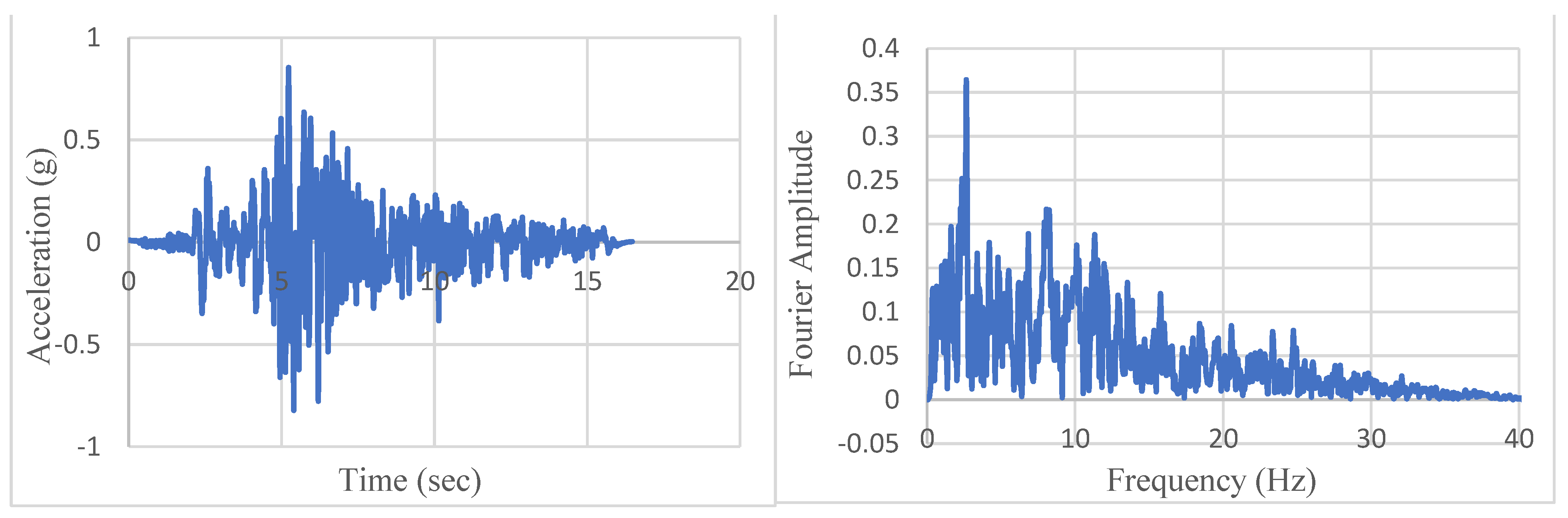
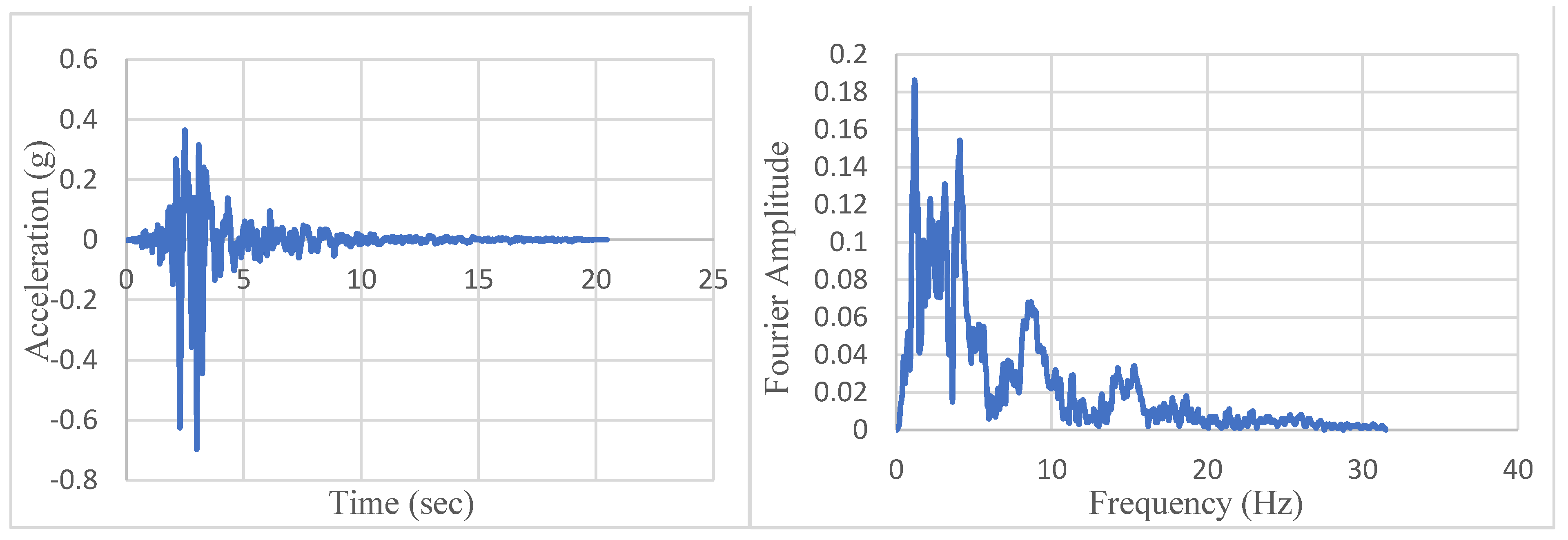
Selected Ground Motions
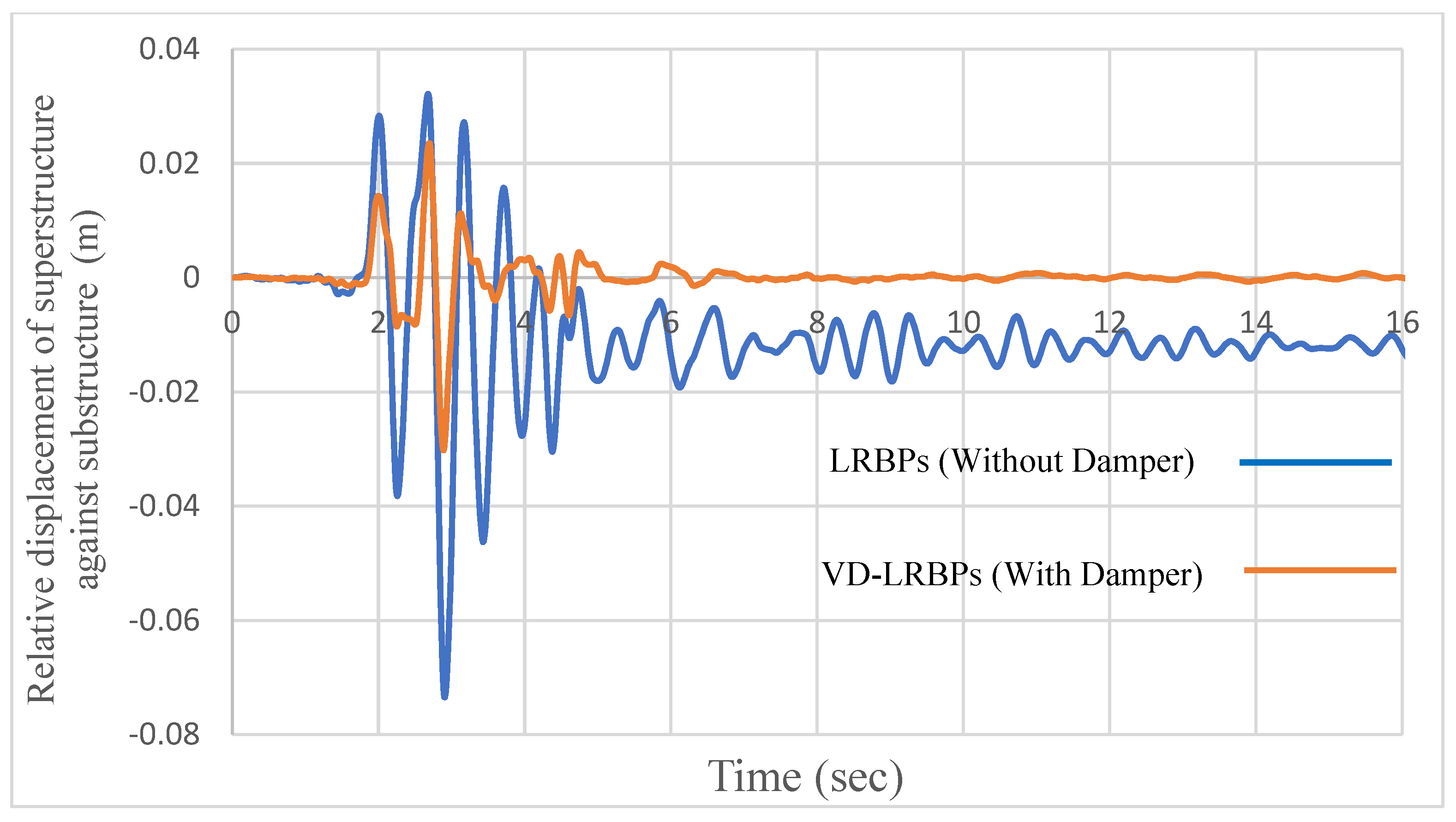
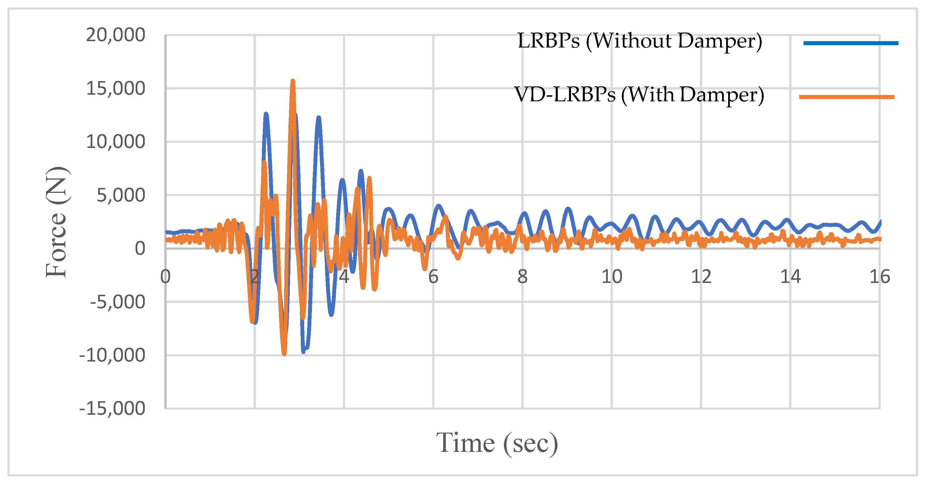
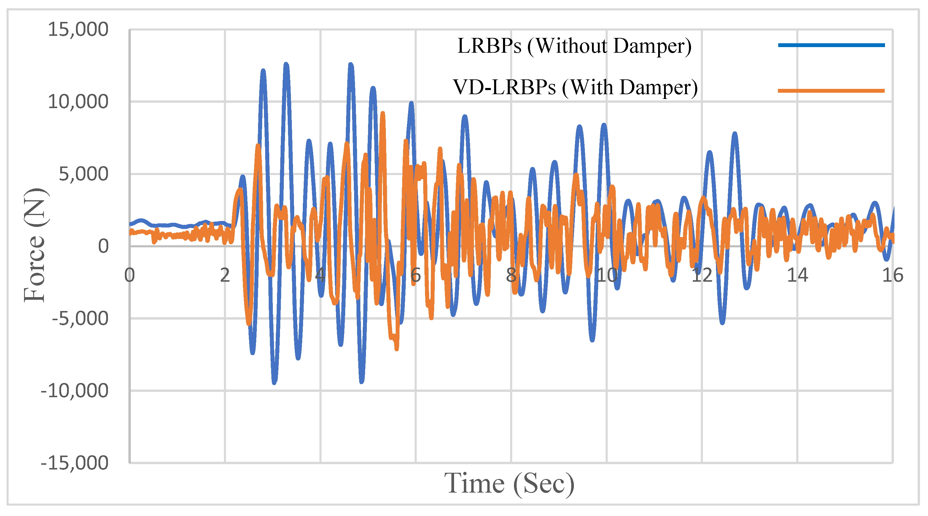
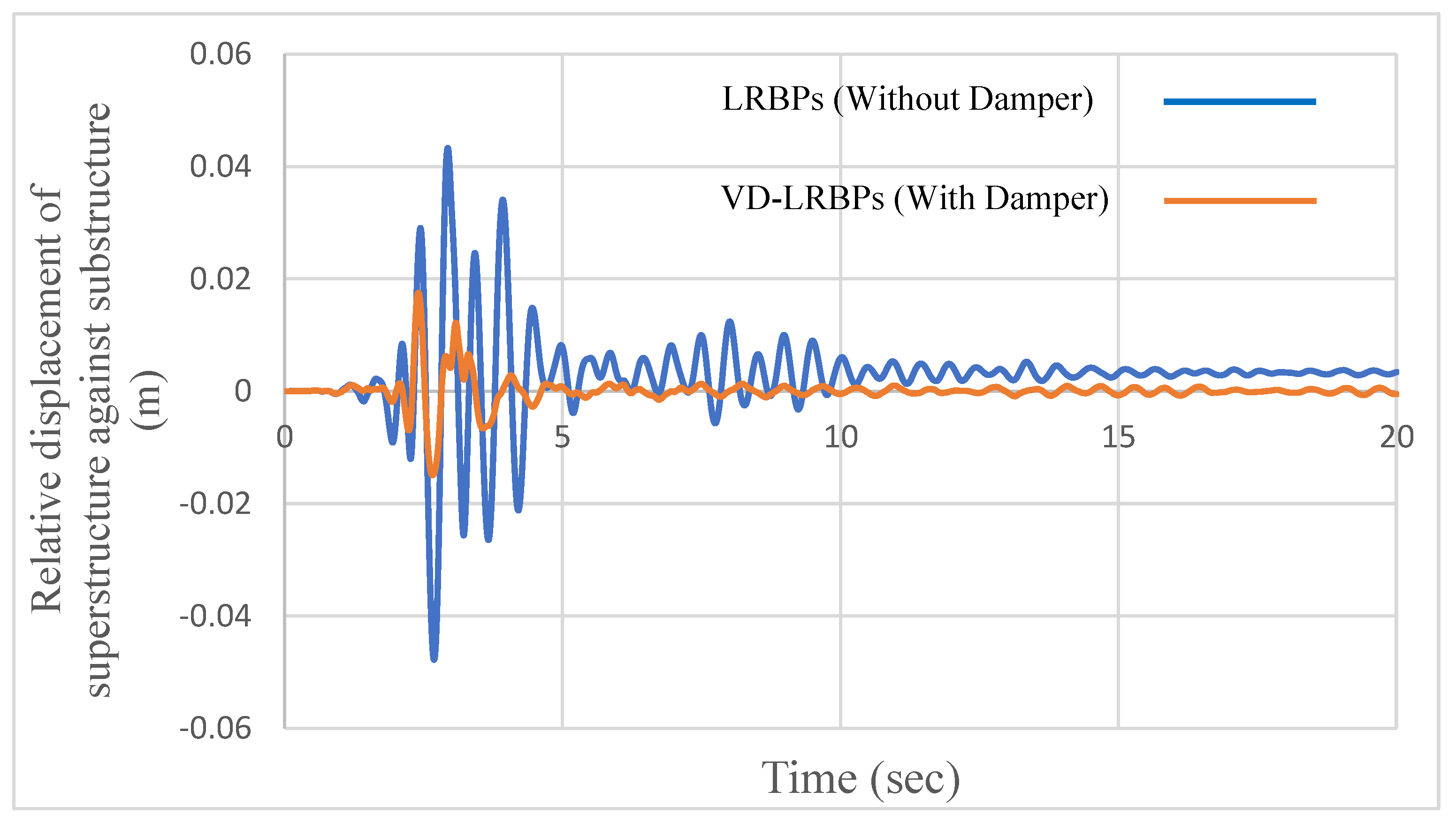
4. Performance of VD-LRBP under Northridge Ground Motion
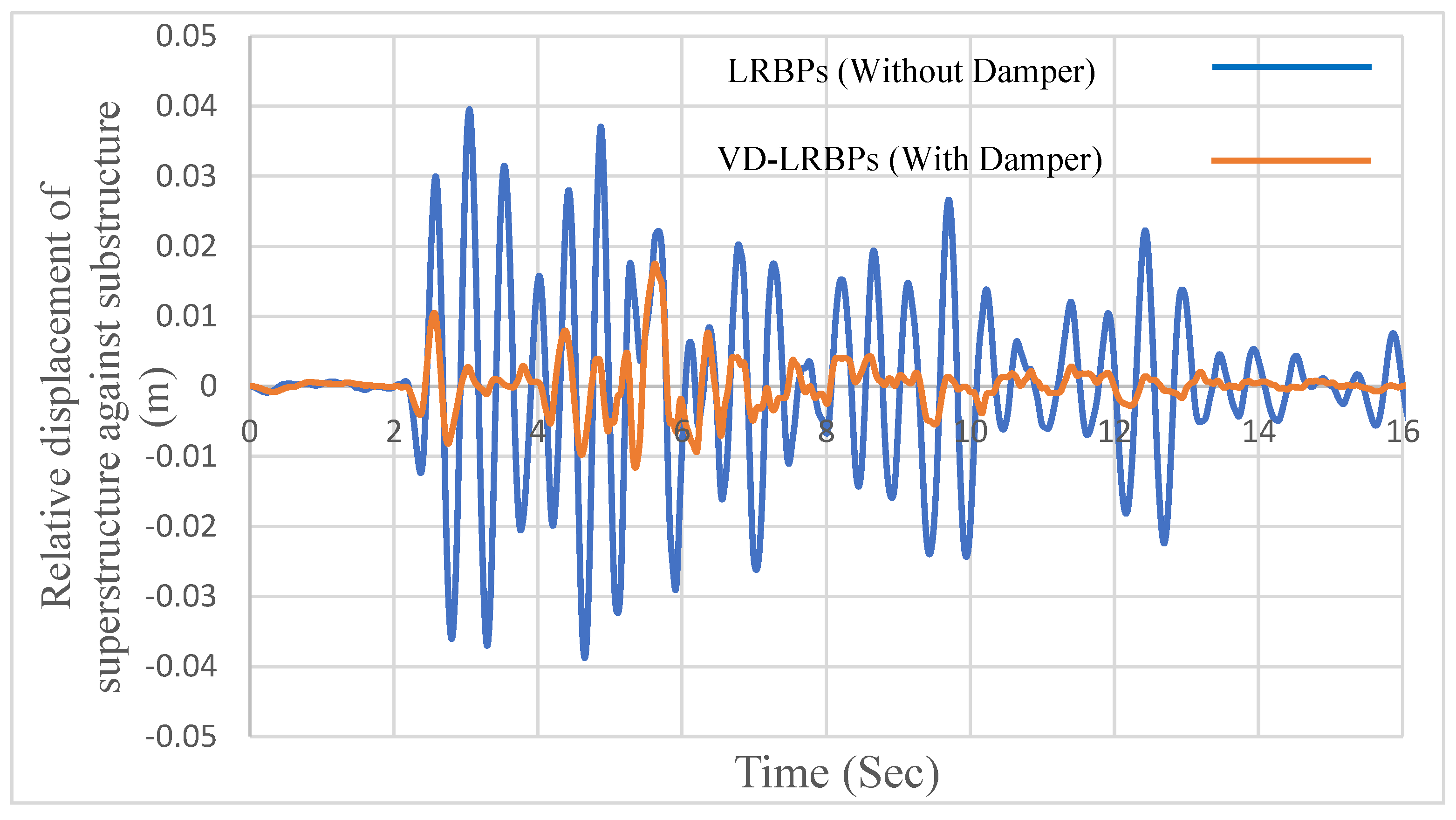
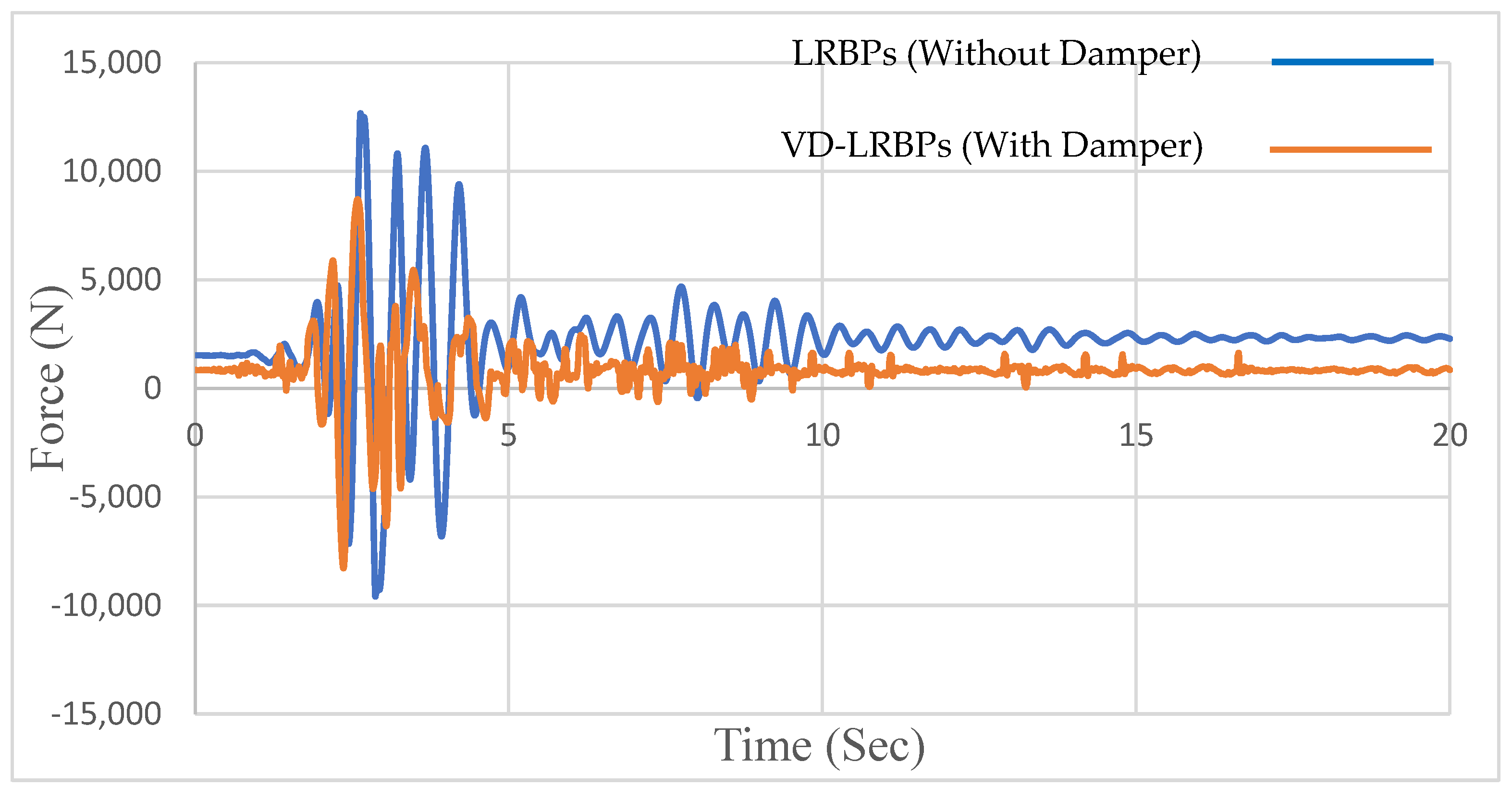
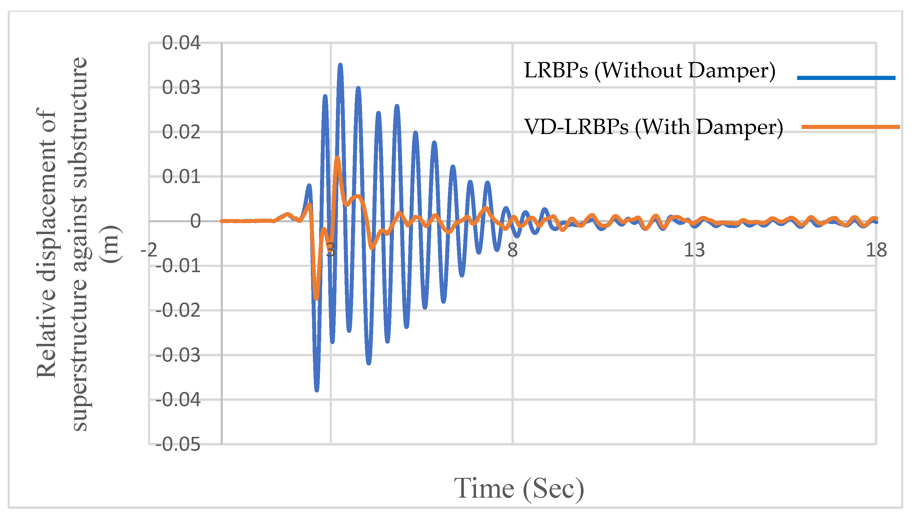
5. Reproducibility and Repeatability of the System Effectiveness
5.1. Tabas Ground Motion Record
5.2. Kobe Ground Motion Record
5.3. El Centro Ground Motion Record
6. Summary and Conclusions
Author Contributions
Funding
Data Availability Statement
Acknowledgments
Conflicts of Interest
References
- Kawashima, K.; Takahashi, Y.; Ge, H.; Wu, Z.; Zhang, J. Reconnaissance report on damage of bridges in 2008 Wenchuan, China, earthquake. J. Earthq. Eng. 2009, 13, 965–996. [Google Scholar] [CrossRef]
- Xiang, N.; Goto, Y.; Obata, M.; Alam, M.S. Passive seismic unseating prevention strategies implemented in highway bridges: A state-of-the-art review. Eng. Struct. 2019, 194, 77–93. [Google Scholar] [CrossRef]
- Kawashima, K.; Unjoh, S.; Hoshikuma, J.-I.; Kosa, K. Damage of bridges due to the 2010 Maule, Chile, earthquake. J. Earthq. Eng. 2011, 15, 1036–1068. [Google Scholar] [CrossRef]
- Schanack, F.; Valdebenito, G.; Alvial, J. Seismic damage to bridges during the 27 February 2010 magnitude 8.8 Chile earthquake. Earthq. Spectra 2012, 28, 301–315. [Google Scholar] [CrossRef]
- Buckle, I. The Northridge, California Earthquake of January 11, 1994: Performance of Highway Bridges; Tech. Rep; NCEER: New York, NY, USA, 1994. [Google Scholar]
- Xiang, N.; Li, J. Seismic Performance of Highway Bridges with Different Transverse Unseating-Prevention Devices. J. Bridg. Eng. 2016, 21, 4016045. [Google Scholar] [CrossRef]
- Li, J.; Xiang, N.; Tang, H.; Guan, Z. Shake-table tests and numerical simulation of an innovative isolation system for highway bridges. Soil Dyn. Earthq. Eng. 2016, 86, 55–70. [Google Scholar] [CrossRef]
- Xiang, N.; Li, J. Experimental and numerical study on seismic sliding mechanism of laminated-rubber bearings. Eng. Struct. 2017, 141, 159–174. [Google Scholar] [CrossRef]
- Maghsoudi-Barmi, A.; Khaloo, A. Experimental investigation of life-time performance of unbounded natural rubber bearings as an isolation system in bridges. Struct. Infrastruct. Eng. 2021, 17, 1096–1109. [Google Scholar] [CrossRef]
- Xiang, N.; Goto, Y.; Alam, M.S.; Li, J. Effect of bonding or unbonding on seismic behavior of bridge elastomeric bearings: Lessons learned from past earthquakes in China and Japan and inspirations for future design. Adv. Bridg. Eng. 2021, 2, 14. [Google Scholar] [CrossRef]
- Zhang, B.; Wang, K.; Lu, G.; Guo, W. Seismic Response Analysis and Evaluation of Laminated Rubber Bearing Supported Bridge Based on the Artificial Neural Network. Shock Vib. 2021, 2021, 5566874. [Google Scholar]
- Han, Q.; Du, X.; Liu, J.; Li, Z.; Li, L.; Zhao, J. Seismic damage of highway bridges during the 2008 Wenchuan earthquake. Earthq. Eng. Eng. Vib. 2009, 8, 263–273. [Google Scholar] [CrossRef]
- Li, J.; Peng, T.; Xu, Y. Damage investigation of girder bridges under the Wenchuan earthquake and corresponding seismic design recommendations. Earthq. Eng. Eng. Vib. 2008, 7, 337–344. [Google Scholar] [CrossRef]
- Chang, K.C.; Kuo, K.Y.; Liu, K.Y.; Lu, C.H. On seismic retrofit strategies of highway bridges-experiences learned from Chi-Chi earthquake. In Proceedings of the 13th World Conference on Earthquake Engineering, Vancouver, BC, Canada, 1–6 August 2004. [Google Scholar]
- Lu, C.-H.; Liu, K.-Y.; Chang, K.-C. Seismic performance of bridges with rubber bearings: Lessons learnt from the 1999 Chi-Chi Taiwan earthquake. J. Chin. Inst. Eng. 2011, 34, 889–904. [Google Scholar] [CrossRef]
- Kuang-Yen, L.; Kuo-Chun, C. Parametric study on performance of bridge retrofitted by unseating prevention devices. Earthq. Eng. Eng. Vib. 2006, 5, 111–118. [Google Scholar] [CrossRef]
- Filipov, E.T.; Revell, J.R.; Fahnestock, L.A.; LaFave, J.M.; Hajjar, J.F.; Foutch, D.A.; Steelman, J.S. Seismic performance of highway bridges with fusing bearing components for quasi-isolation. Earthq. Eng. Struct. Dyn. 2013, 42, 1375–1394. [Google Scholar] [CrossRef]
- Filipov, E.T.; Fahnestock, L.A.; Steelman, J.S.; Hajjar, J.F.; LaFave, J.M.; Foutch, D.A. Evaluation of quasi-isolated seismic bridge behavior using nonlinear bearing models. Eng. Struct. 2013, 49, 168–181. [Google Scholar] [CrossRef]
- Steelman, J.S. Sacrificial Bearing Components for Quasi-Isolated Response of Bridges Subject to High-Magnitude, Low-Probability Seismic Hazard; University of Illinois at Urbana-Champaign: Champaign, IL, USA, 2013; ISBN 1303803127. [Google Scholar]
- Moslehi Tabar, A.; De Domenico, D.; Dindari, H. Seismic Rehabilitation of Steel Arch Bridges Using Nonlinear Viscous Dampers: Application to a Case Study. Pract. Period. Struct. Des. Constr. 2021, 26, 4021012. [Google Scholar] [CrossRef]
- Mavrakis, G. Greece’s new high-speed railway line: Detailed design and construction engineering of bridge SG26. Ce/Papers 2021, 4, 249–254. [Google Scholar] [CrossRef]
- Liu, Q.; Zhu, S.; Yu, W.; Wu, X.; Song, F.; Ren, X. Ground Motion Frequency Insensitivity of Bearing-Supported Pedestrian Bridge with Viscous Dampers. KSCE J. Civ. Eng. 2021, 25, 2662–2673. [Google Scholar] [CrossRef]
- Hu, X.; Zhang, R.; Ren, X.; Pan, C.; Zhang, X.; Li, H. Simplified design method for structure with viscous damper based on the specified damping distribution pattern. J. Earthq. Eng. 2020, 2020, 1–21. [Google Scholar] [CrossRef]
- Zhou, L.; Wang, X.; Ye, A. Shake table test on transverse steel damper seismic system for long span cable-stayed bridges. Eng. Struct. 2019, 179, 106–119. [Google Scholar] [CrossRef]
- Xu, Y.; Wang, R.; Li, J. Experimental verification of a cable-stayed bridge model using passive energy dissipation devices. J. Bridg. Eng. 2016, 21, 4016092. [Google Scholar] [CrossRef]
- Dai Nguyen, X.; Guizani, L. Analytical and numerical investigation of natural rubber bearings incorporating U-shaped dampers behaviour for seismic isolation. Eng. Struct. 2021, 243, 112647. [Google Scholar] [CrossRef]
- Tang, H.; Li, J.Z. Displacement control method for continuous bridges on laminated rubber bearings under earthquake excitation. China J. Highw. Transp. 2013, 26, 110–116. [Google Scholar]
- Jiang, J.; Li, J.; Fan, L. Study on Aseismic Performance of Combination of Laminated Rubber Bearing and Viscous Damper for Bridge. J. Highw. Transp. Res. Dev. 2005, 2005, 8. [Google Scholar]
- Xiang, N.; Alam, M.S.; Li, J. Yielding steel dampers as restraining devices to control seismic sliding of laminated rubber bearings for highway bridges: Analytical and experimental study. J. Bridg. Eng. 2019, 24, 4019103. [Google Scholar] [CrossRef]
- AASHTO. AASHTO LRFD Bridge Design Specifications, 8th ed.; American Association of State Highway and Transportation Officials: Washington, DC, USA, 2017. [Google Scholar]
- Laminated Rubber Bearing Pad. Available online: https://civildigital.com/base-isolation-system-outline-on-principles-types-advantages-applications/ (accessed on 1 October 2021).
- Ghiasian, M.; Fakher, A.; Khanmohammadi, M. Enhancing the Seismic Performance of Batter Piles in Pile-Supported Wharves Using Fluid Viscous Dampers. Available online: https://www.researchgate.net/profile/Mohammad-Ghiasian/publication/344978757_Enhancing_the_seismic_performance_of_batter_piles_in_pile-supported_wharves_using_fluid_viscous_dampers/links/5fa1ec04458515b7cfba41a6/Enhancing-the-seismic-performance-of-batter-piles-in-pile-supported-wharves-using-fluid-viscous-dampers.pdf (accessed on 1 October 2021).
- Soneji, B.B.; Jangid, R.S. Passive hybrid systems for earthquake protection of cable-stayed bridge. Eng. Struct. 2007, 29, 57–70. [Google Scholar] [CrossRef]
- Martínez-Rodrigo, M.D.; Filiatrault, A. A case study on the application of passive control and seismic isolation techniques to cable-stayed bridges: A comparative investigation through non-linear dynamic analyses. Eng. Struct. 2015, 99, 232–252. [Google Scholar] [CrossRef]
- Xu, Y.; Tong, C.; Li, J. Simplified calculation method for supplemental viscous dampers of cable-stayed bridges under near-fault ground motions. J. Earthq. Eng. 2021, 25, 65–81. [Google Scholar] [CrossRef]
- Tabatabai, H.; Mehrabi, A.B. Design of mechanical viscous dampers for stay cables. J. Bridg. Eng. 2000, 5, 114–123. [Google Scholar] [CrossRef]
- Zhu, J.; Zhang, W.; Zheng, K.F.; Li, H.G. Seismic design of a long-span cable-stayed bridge with fluid viscous dampers. Pract. Periodical Struct. Des. Constr. 2016, 21, 04015006. [Google Scholar] [CrossRef]
- Li, J.; Yan, J.; Peng, T.; Han, L. Shake table studies of seismic structural systems of a Taizhou Changjiang highway bridge model. J. Bridg. Eng. 2015, 20, 4014065. [Google Scholar] [CrossRef]
- Guo, T.; Liu, J.; Huang, L. Investigation and control of excessive cumulative girder movements of long-span steel suspension bridges. Eng. Struct. 2016, 125, 217–226. [Google Scholar] [CrossRef]
- Kiran, J.; Krishnakumar, S.; Alex, F.; Mohanan, N. Seismic Performance of a Pre stressed Tied Arch bridge Fitted With Dampers. Int. Res. J. Eng. Technol. 2016, 3, 1454–1460. [Google Scholar]
- Agrawal, A.K.; Amjadian, M. Seismic component devices. In Innovative Bridge Design Handbook; Elsevier: Amsterdam, The Netherlands, 2016; pp. 531–553. [Google Scholar]
- Lee, D.; Taylor, D.P. Viscous damper development and future trends. Struct. Des. Tall Build. 2001, 10, 311–320. [Google Scholar] [CrossRef]
- Xiang, N.; Alam, M.S.; Li, J. Shake table studies of a highway bridge model by allowing the sliding of laminated-rubber bearings with and without restraining devices. Eng. Struct. 2018, 171, 583–601. [Google Scholar] [CrossRef]
- Yi, J.; Zhou, J.; Ye, X. Seismic Control of Cable-stayed Bridge Using Negative Stiffness Device and Fluid Viscous Damper under Near-field Ground Motions. J. Earthq. Eng. 2020, 2020, 1–18. [Google Scholar] [CrossRef]
- Wen, J.; Han, Q.; Xie, Y.; Du, X.; Zhang, J. Performance-based seismic design and optimization of damper devices for cable-stayed bridge. Eng. Struct. 2021, 237, 112043. [Google Scholar] [CrossRef]


| Beam Elements | ||
|---|---|---|
| Command: | Element elasticBeamColumn | SI Units (m, k, s) |
| A | cross-sectional area of element | |
| E | Young’s Modulus | |
| G | Shear Modulus | |
| J | Torsional moment of inertia of cross section * | |
| Iz | Second moment of area about the local z-axis * | |
| Iy | Second moment of area about the local y-axis * | |
| transfTag | Identifier for previously-defined coordinate-transformation (CrdTransf) object | (0, 0, 1) |
| Material Properties of Confined Concrete (Units: Pascal (N/m2)) | ||
|---|---|---|
| Command | uniaxialMaterial Concrete01 | |
| fpc | concrete compressive strength at 28 days (compression is negative) | |
| epsc0 | concrete strain at maximum strength | |
| fpcu | concrete crushing strength | |
| epsU | concrete strain at crushing strength | |
| Material Properties of Unconfined Concrete (Units: Pascal (N/m2)) | ||
|---|---|---|
| Command | uniaxialMaterial Concrete01 | |
| fpc | concrete compressive strength at 28 days (compression is negative) | |
| epsc0 | concrete strain at maximum strength | |
| fpcu | concrete crushing strength | |
| epsU | concrete strain at crushing strength | |
| Material Properties of Reinforcing Bars (Units: N and Pascal (N/m2)) | ||
|---|---|---|
| Command | uniaxialMaterial Steel02 | |
| Fy | yield strength | |
| E | initial elastic tangent | |
| b | strain-hardening ratio (ratio between post-yield tangent and initial elastic tangent) | |
| Modeling the LRBP (Units: Pascal (N/m2)) | ||
|---|---|---|
| Command | Flat Slider Bearing Element | |
| frnMdlTag | previously-defined FrictionModel | Coulomb Friction |
| kInit | initial elastic stiffness in local shear direction | |
| P matTag | previously-defined UniaxialMaterial in axial direction | Rigid |
| T matTag | previously-defined UniaxialMaterial in torsional direction | |
| My matTag | previously-defined UniaxialMaterial in moment direction around local y-axis | |
| Mz matTag | previously-defined UniaxialMaterial in moment direction around local z-axis | |
| Earthquake Station | RSN (s) | Magnitude |
|---|---|---|
| Northridge Newhall Fire | 1044 | 6.69 |
| TABAS | 143 | 7.35 |
| Kobe (Japan) | 1119 | 6.9 |
| Imperial Valley (El Centro) | 182 | 6.53 |
Publisher’s Note: MDPI stays neutral with regard to jurisdictional claims in published maps and institutional affiliations. |
© 2021 by the authors. Licensee MDPI, Basel, Switzerland. This article is an open access article distributed under the terms and conditions of the Creative Commons Attribution (CC BY) license (https://creativecommons.org/licenses/by/4.0/).
Share and Cite
Khedmatgozar Dolati, S.S.; Mehrabi, A.; Khedmatgozar Dolati, S.S. Application of Viscous Damper and Laminated Rubber Bearing Pads for Bridges in Seismic Regions. Metals 2021, 11, 1666. https://doi.org/10.3390/met11111666
Khedmatgozar Dolati SS, Mehrabi A, Khedmatgozar Dolati SS. Application of Viscous Damper and Laminated Rubber Bearing Pads for Bridges in Seismic Regions. Metals. 2021; 11(11):1666. https://doi.org/10.3390/met11111666
Chicago/Turabian StyleKhedmatgozar Dolati, Seyed Saman, Armin Mehrabi, and Seyed Sasan Khedmatgozar Dolati. 2021. "Application of Viscous Damper and Laminated Rubber Bearing Pads for Bridges in Seismic Regions" Metals 11, no. 11: 1666. https://doi.org/10.3390/met11111666
APA StyleKhedmatgozar Dolati, S. S., Mehrabi, A., & Khedmatgozar Dolati, S. S. (2021). Application of Viscous Damper and Laminated Rubber Bearing Pads for Bridges in Seismic Regions. Metals, 11(11), 1666. https://doi.org/10.3390/met11111666