Article

Numerical and Experimental Evaluation of a CFRP Fatigue Strengthening for Stringer-Floor Beam Connections in a 19th Century Riveted Railway Bridge

by
J. David Jimenez-Vicaria
1,2,*,
M. Dolores Gomez-Pulido
3 and
Daniel Castro-Fresno
2
1
Centro Tecnológico, ACCIONA Construcción, Valportillo Segunda 8, 28108 Alcobendas, Spain
2
GITECO Research Group, Universidad de Cantabria, Avda. de los Castros 44, 39005 Santander, Spain
3
Instituto CC Eduardo Torroja-CSIC, Serrano Galvache 4, 28033 Madrid, Spain
*
Author to whom correspondence should be addressed.
Metals 2021, 11(4), 603; https://doi.org/10.3390/met11040603
Submission received: 6 March 2021 / Revised: 29 March 2021 / Accepted: 31 March 2021 / Published: 7 April 2021

Abstract

:
A local and global finite element analysis of the stringer-floor beam connection of a 19th century riveted railway bridge in Spain made of puddle iron were performed to obtain the maximum principal strains in the riveted connecting angles corresponding to bending moments from train loading on the bridge. Due to the anisotropic nature of puddle iron, the connecting angles were modelled using Hill anisotropic plasticity potential and a parametric study in the local FE model of the connection was performed. A laboratory specimen fabricated with original stringers dismantled from the railway bridge was tested to calibrate the numerical models, so the yield stress ratio that best fitted experimental results was obtained. Based on the method of constant fatigue-life diagram and modified Goodman fatigue failure criterion, it was detected that the connecting angles were prone to fatigue crack initiation, as the combination of mean stress and alternating stress amplitude at the toe of the angle fillet remained outside the infinite fatigue-life region. An innovative strengthening system based on adhesively-bonded carbon-fiber reinforced polymer (CFRP) angles was designed to prevent fatigue crack initiation in the connecting angles of the stringer-floor beam connection. Different CFRP laminate layouts were numerically evaluated and a proper configuration was obtained that reduced both the mean stress and the alternating stress amplitude in the connecting angle to shift from finite fatigue-life region to infinite fatigue-life region in the constant fatigue-life diagram. To validate the effectiveness of the proposed CFRP strengthening method, its application on a second laboratory specimen fabricated with original stringers was evaluated experimentally and compared with numerical results. The research study conducted showed that the use of adhesively-bonded CFRP angles was an effective strengthening system in reducing the stress level in the fillet region of the puddle iron connecting angles (where fatigue cracks are prone to initiate) and consequently could increase fatigue life of the stringer-floor beam connection.

Graphical Abstract

1. Introduction

In Europe, more than 35% of railway bridges are more than 100 years old [1], so they are reaching the end of their expected service life. Many riveted metallic railway bridges constructed from the end of the 19th century to the beginning of the 20th century are still in operation and are often subjected to heavier loads than those for which they were originally designed. In view of the large number of riveted railway bridges in Europe, as well as their considerable age, strengthening of these structures to extend their remaining life is a worldwide priority requiring attention of bridge engineers, which is economically and environmentally preferable to demolishing and replacing them with new bridges.
Old riveted metallic railway bridges have been subjected to a large number of cyclic loads during their service life, so many of them could experience fatigue damage in certain construction details, limiting their residual life. A typical fatigue-prone detail found in these bridges is the stringer-floor beam connection by means of connecting angles riveted to both the stringer and floor-beam webs. A relatively large number of damage cases have been reported for stringer-floor beam connections in riveted metallic bridges [2,3]. These connections have some rotational stiffness, partially restraining the rotation of stringer ends [4]. Consequently, bending moment develops at stringers ends, subjecting the connecting angles to tensile stresses that might be high enough to result in fatigue cracking at the angle fillet [5]. To prevent the fatigue crack initiation of connecting angles and consequently to extend the service life of these connections, the stresses in those fatigue-prone details could be reduced by the application of strengthening strategies.
CFRP plates adhesively-bonded to the connection may result in a promising technique to reduce stress levels in these fatigue-prone areas. The advantages of this technique, compared to the traditional repairing method based on bolted or welded steel plates, are related to the drawbacks inherent to these traditional techniques. Existing riveted bridges are made of metallic materials that are not always weldable and holes drilled for bolted connection of strengthening plates may weaken even more the element and reduce fatigue life. In addition, CFRP plates do not corrode and are lightweight, which is advantageous compared to steel strengthening plates [6].
Many research works have proved the efficiency of adhesively-bonded CFRP plates to increase the fatigue life of metallic structures. Most of them focused on the study of the fatigue resistance of the bond between the CFRP plate and the metal substrate in strengthened tensile members [7,8,9] or flexural members (beams) strengthened at the bottom (tensile) flange [10,11,12,13], both using laboratory-scale specimens. A limited number of field applications of CFRP-strengthening of old metallic bridges or laboratory tests with real-scale specimens dismantled from bridges have been reported in the literature [14,15]. Recently, a 122-year-old roadway metallic bridge in Melbourne (Australia) was strengthened using two different retrofitting techniques using CFRP plates for the reduction of tensile stresses in the bottom flange of the I-section cross-girders of the bridge [16]. On-site short-term strain measurements before and after strengthening demonstrated that the tensile stresses in the bottom flange of the cross-girders were reduced approximately 15% and 44% by the application of the proposed nonprestressed bonded and prestressed unbonded CFRP plates, respectively. Similarly, a roadway steel welded bridge in Madrid (Spain), built around 1965, was retrofitted by the adhesion of CFRP plates placed transversally to butt welds subjected to cyclic tension forces in the bottom flange of the main longitudinal steel girders [17]. From on-site strain measurements, a 20–30% stress reduction in the butt welds was obtained after CFRP strengthening, allowing for an increase in the remaining service life of these fatigue-prone details.
All these studies and interventions focused on the strengthening of metallic elements subjected to tension forces (e.g., bottom flanges of girders in flexure) and not on the connections between different elements in the structure (e.g., stringer-floor beam connections). For stringer-floor beam riveted connections, finding an effective strengthening solution is a considerable challenge owing to the lack of space for the intervention, the presence of rivets and the complexity of the geometry in these details. A recently published research study proposed the application of prestressed CFRP rods for strengthening stringer-floor beam connections in old riveted metallic bridges [18]. This system consisted of a mechanical wedge-barrel anchor to hold the prestressed CFRP rod and a clamping system attached to the parent structure to transmit forces via friction. These prestressed CFRP rods applied a compressive load on both sides of the stringer and consequently, a sagging moment opposing the out-of-plane deformation of the angles, which resulted in a reduction of more than 40% of the tensile stresses at critical locations in the connecting angles. Despite this innovative system developed in [18], authors of the present research work consider that there is a lack of strengthening strategies using adhesively-bonded CFRP for the connections between different members of metallic bridges (such us stringer-floor beam connections), which are often more critical with reference to fatigue [4] than tensile or flexural members.
An innovative strengthening system based on adhesively-bonded CFRP angles was designed and evaluated in this article to extend the fatigue life of stringer-floor beam connections of riveted metallic railway bridges. A method based on the constant fatigue-life diagram [19] was used for the design of a proper CFRP strengthening system required to prevent fatigue crack initiation in connecting angles of stringer-floor beam connections. To confirm the effectiveness of the proposed strengthening method, its application on a laboratory specimen fabricated with original stringers dismantled from a 19th century riveted railway bridge in Spain was evaluated experimentally and compared with numerical results. Static bending loading tests were performed on both non-strengthened and strengthened stringer-floor beam connection specimens to confirm the effects of strengthening method in reducing stress range in the fatigue-prone detail, highlighting the possibility of utilizing such a preventive strategy before fatigue crack initiation to increase the lifetime of these connections.

2. Global FE Model of Redondela Bridge

2.1. Bridge Description

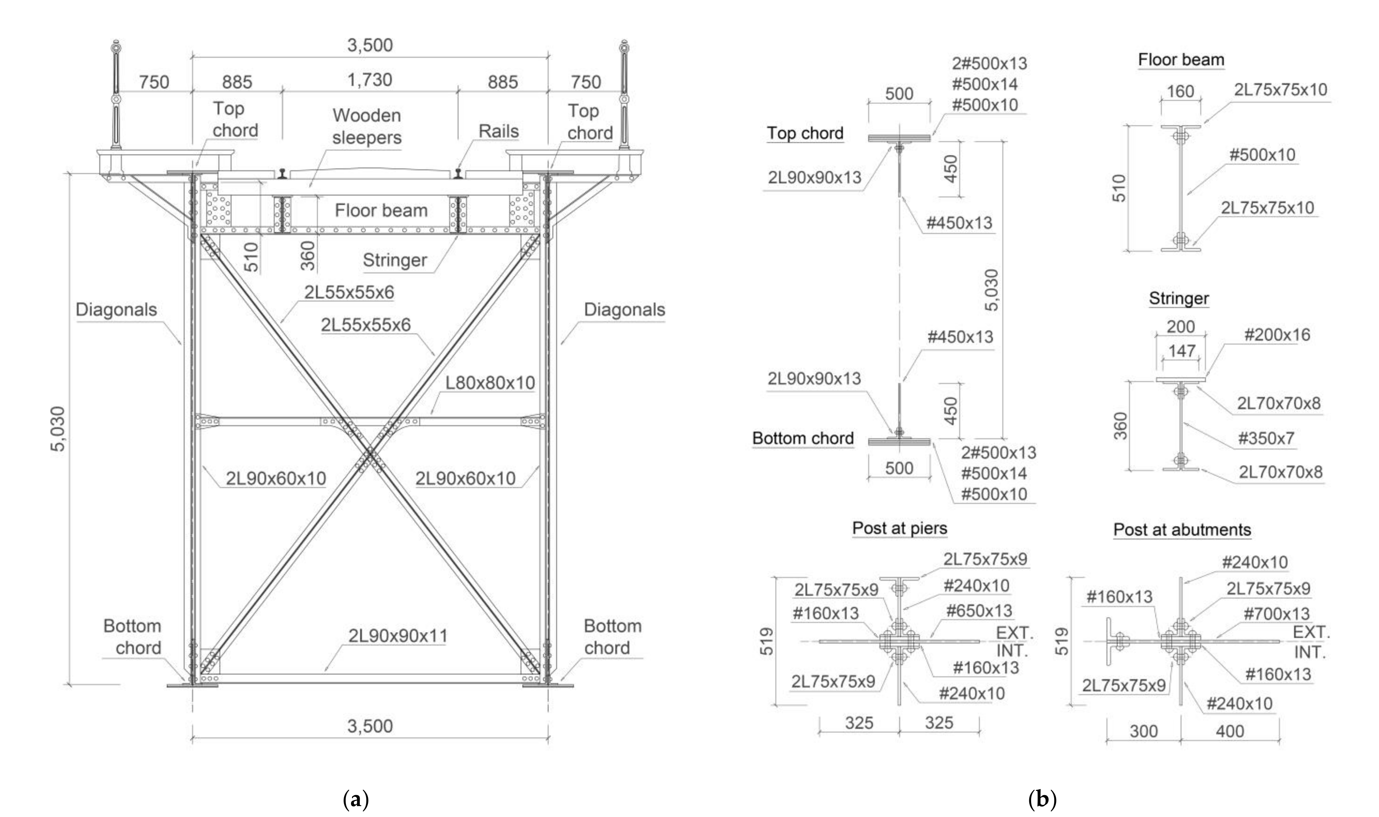
Redondela Bridge was built in 1884 by the Spanish company La Maquinista Terrestre y Marítima using puddle iron as the construction material [9] and it is still in operation. According to the Spanish Railway Infrastructure Administrator (Adif), trains speed on this bridge is limited to 80 km/h. As reported in the original project and drawings [20], it is a three-span symmetric continuous riveted truss bridge over Alvedosa River in Redondela (Pontevedra, Spain), with a total length of 149.5 m (central span 57.5 m and two lateral spans 46.0 m each), supported on two intermediate metallic truss piers (17.3 m high) and masonry abutments. The main longitudinal girders are two riveted parallel trusses 5.2 m high and 3.5 m apart, with 65 panels separated every 2.3 m (Figure 1). As shown in Figure 2, both top and bottom chords of the main girders consist of combined riveted plates (a vertical plate 450 × 13 mm and a horizontal plate 500 × 13 mm) and two L90 × 90 × 13 mm angles, creating a T-shaped cross-section. The bottom chord has the same geometry as the upper chord, but the T-shaped section is reversed upside down. Additional horizontal plates (500 × 13 mm, 500 × 14 mm and 500 × 10 mm) are added to both top and bottom chords cross-sections at different locations along the length of the bridge to resist the corresponding bending moment (Figure 1).
At the top chord, the main girders are connected transversally by double-T riveted floor beams, composed of a 500 × 10 mm vertical plate and four L75 × 75 × 10 mm angles (Figure 2b) and separated every 2.3 m (panel length). These floor beams are connected longitudinally by double-T riveted stringers, which comprise a 350 × 7 mm vertical plate, four L70 × 70 × 8 mm angles and also a 200 × 16 mm steel plate (Figure 2b) welded to its top flange angles during strengthening works in the past (not included in original drawings). The wooden sleepers rely on the stringers and the rails are vertically coincident with the stringers. In addition, the main girders are transversally connected, every 2.3 m, by a vertical cross bracing system with two L55 × 55 × 6 mm angles connecting diagonally top and bottom chords, two L90 × 90 × 11 mm angles connecting the bottom chords and an L80 × 80 × 10 mm angle fixed at middle high of main girders (Figure 2a). Finally, a horizontal cross bracing system connects the bottom chords with L100 × 70 × 10 mm angles (plan view in Figure 1).
Top and bottom chords are connected by vertical web members (posts) formed by two L90 × 60 × 10 mm angles (except at piers and abutments, where these posts have an increased cross-section as shown in Figure 2b, according to reactions at supports). In addition, a double lattice of diagonal web members with an inclination of 48.5° with respect to the horizontal is riveted alternately on either side of the chords. The cross-section of diagonals varies between two L75 × 75 × 7 mm angles (diagonal type D1) and a T-section composed of a 180 × 14 mm plate and two L90 × 90 × 13 mm angles (diagonal type D6), depending on its position along the bridge length (Figure 1) to resist corresponding shear forces. The different elements used to build top and bottom chords cross-sections, as well as diagonal cross-sections, are detailed in Table 1.

2.2. Bridge Numerical Model

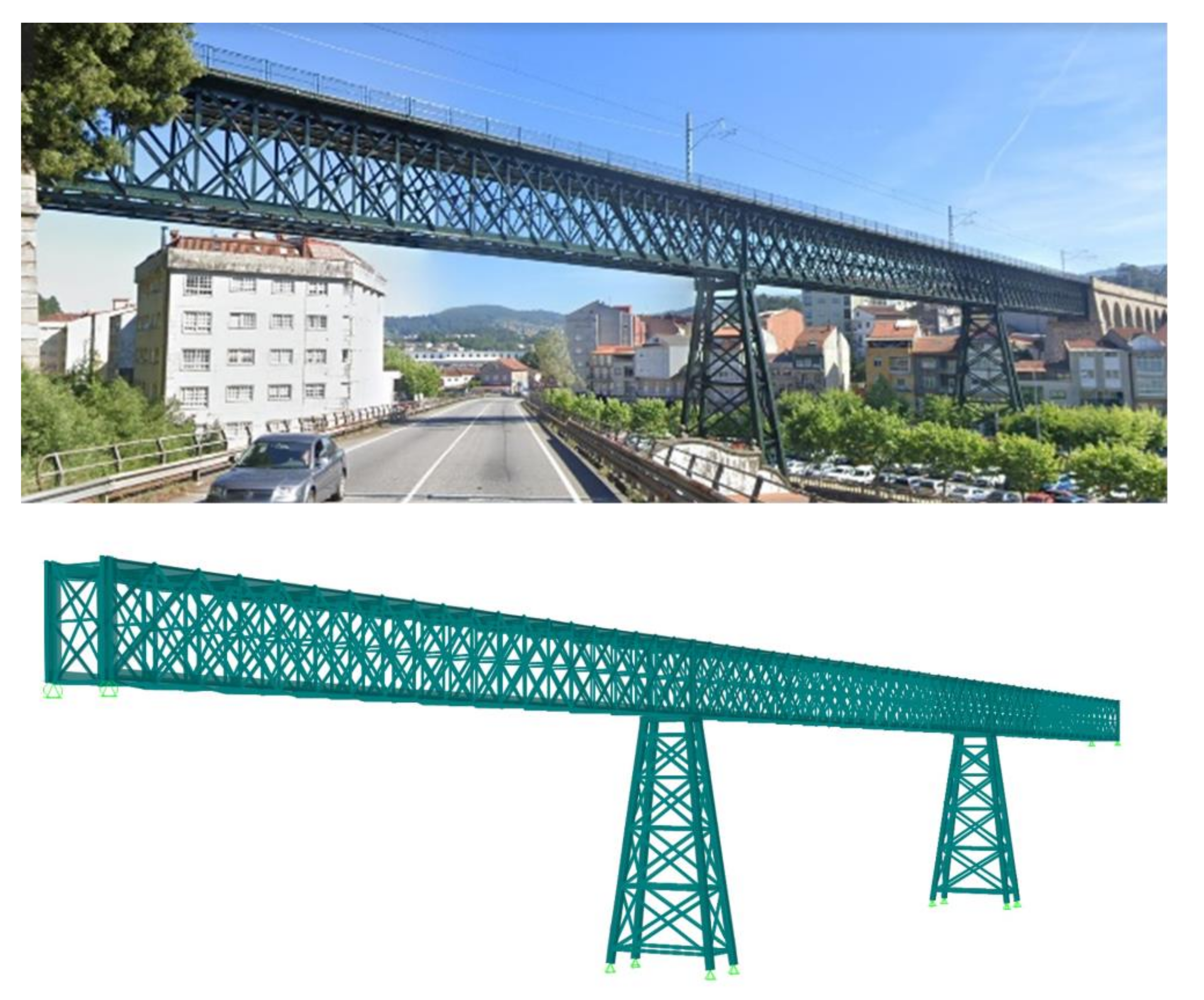
A 3D finite element analysis of Redondela Bridge was performed using software SAP2000® v20 [21] to obtain the maximum bending moment at the stringer-floor beam connections due to train loading. The model geometry was based on the original construction documents of the bridge [20], according to the bridge description in previous section. The model was created using frame elements and rigid connections at joints (moments are transferred through the joints) as suggested in [22,23] for this type of riveted bridges (Figure 3). Only stringer-floor beam connection nodes were modelled with partial fixity springs for moments, which simulates the rotational stiffness of the connection between stringer web and floor beam web by means of riveted connecting angles, which is the fatigue-prone detail of interest in this study. The value of rotational stiffness used in the global FE model of Redondela Bridge was obtained from the moment-rotation curve of the stringer-floor beam connection in the local FE model that is analyzed in the next section.
For this global FE model, nonlinear mechanical properties of the metallic material were not considered, since only service loads were applied in the model and bridge elements are expected to remain below yielding, as also reported in [23,24] for this type of analysis. Only elastic material properties of puddle iron were used, with a modulus of elasticity of 198 GPa and a Poisson coefficient of 0.30, according to a previous characterization of this material [9]. Global boundary conditions of the model simulated the support conditions of the bridge. Original project documents [20] indicated that the bridge was a three-span continuous bridge supported with simple bearing rollers on both abutments and first pier (allowing longitudinal translation), while using pin connections on the second (Pontevedra side) pier (Figure 1).
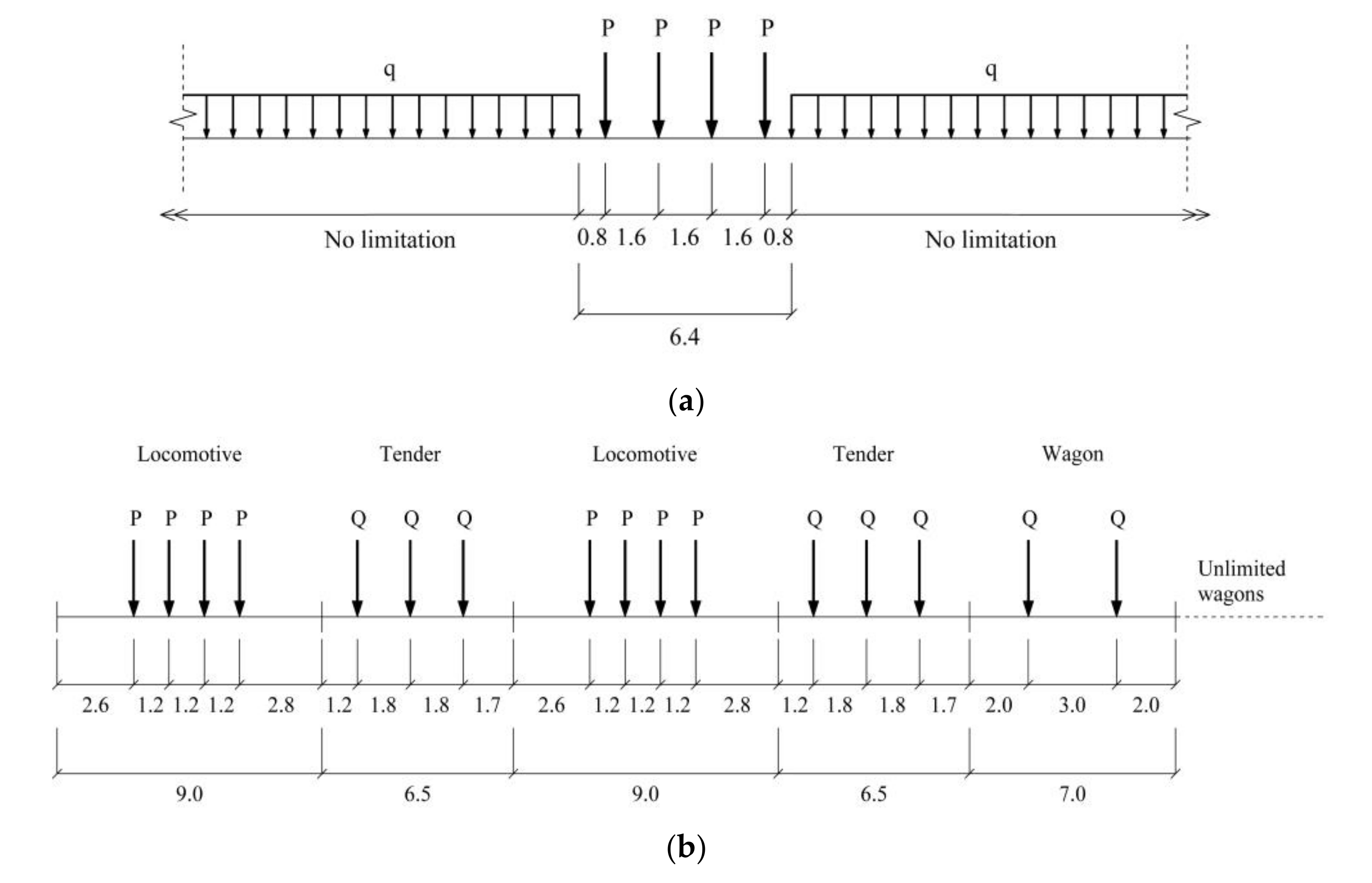
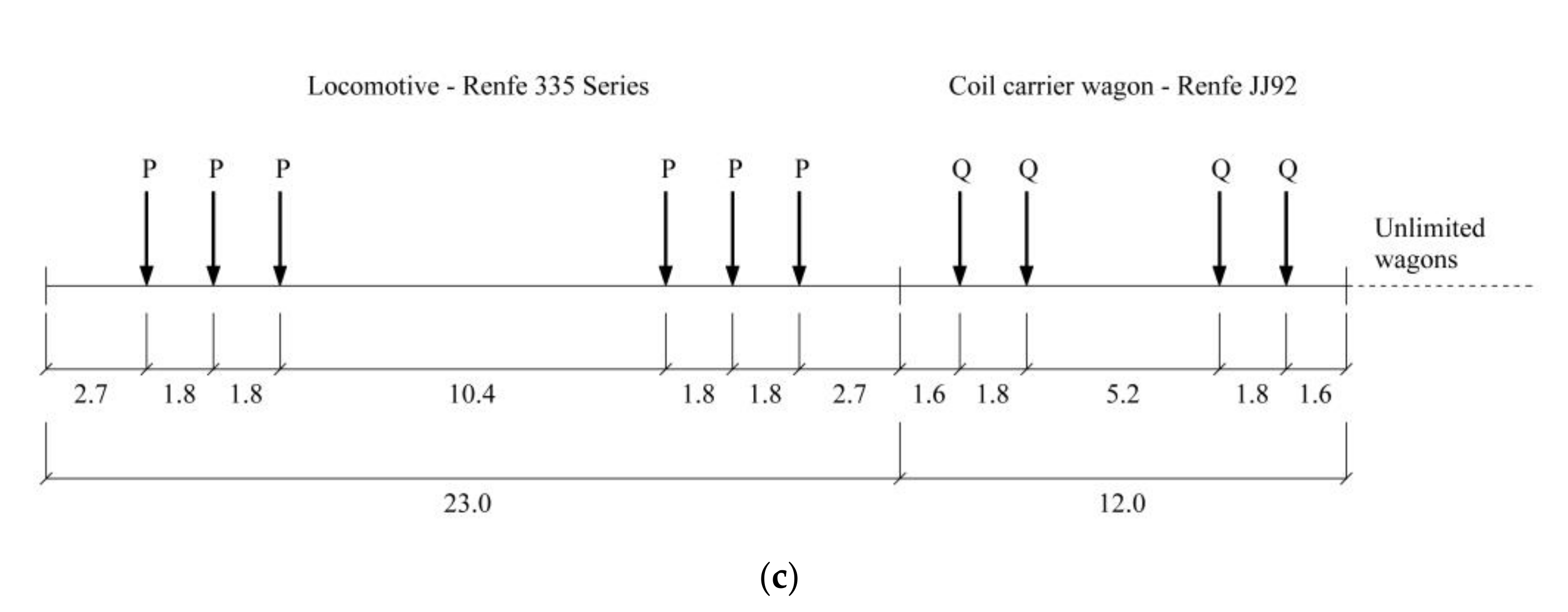
An influence-based moving load analysis with vehicle live load pattern [21] was performed, with axle loads applied directly to the stringer frames, neglecting the beneficial effect of any load spread due to the rails and sleepers. Two paths, one for each rail on the track, were defined in the model and assigned to corresponding stringer frames, where the vehicle load was applied. Since historical traffic loads on the bridge along its service life are not known, the vehicle for fatigue analysis was defined based on the UIC Load Model 71 (Figure 4a), as this is the most common procedure for the determination of maximum stress amplitude in fatigue-prone details of railway bridges, as reported in [25,26,27]. For comparison purposes, two additional vehicle loads based on locomotive-hauled freight trains were defined in the bridge model. The first one is the load model of the Spanish Standard for Railway Bridges published in 1902 (Figure 4b), as this can give an approach of the maximum bending moment at stringer-floor beam connections of the bridge during the first years after the construction of Redondela Bridge. The second one, a common locomotive for freight trains currently used in the Spanish railway network, Renfe 335 Series (Figure 4c), followed by Renfe JJ92 wagons, was also analyzed to consider a more realistic traffic scenario on the bridge. Based on an analysis by the authors of the different wagons offered by Renfe (main railway operator in Spain), Renfe JJ92 wagon is one of their heaviest wagons, so this one was selected from a conservative point of view. The axle loads (P for locomotive and Q for wagons) for each load model considered are shown in Table 2. The self-weight of the bridge metallic members (8 t/m3 to consider elements not modelled [28], such as rivets and other connecting elements) and the superimposed dead load due to the sleepers and rails of the track (adopted as 1 kN/m for each rail) were also taken into account in the global FE model of the bridge.
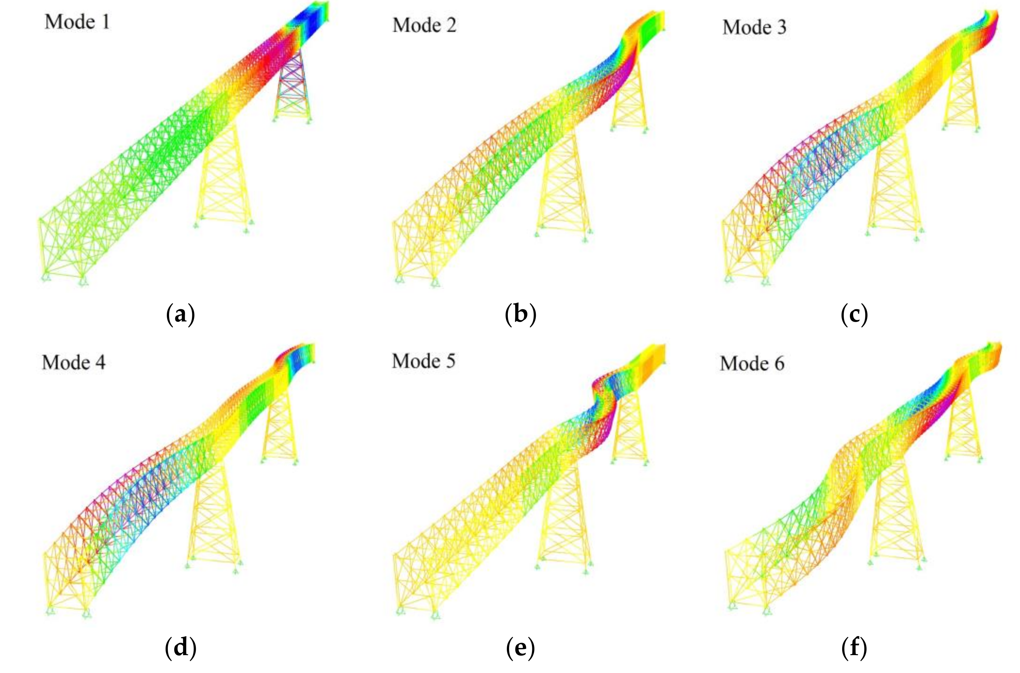
To check if the first natural bending frequency n0 of the bridge is within the limits recommended in [25] to avoid the need of a dynamic analysis (2.00 Hz < n0 < 4.18 Hz for the determinant length of the bridge LФ = 64.8 m), a modal analysis was carried out. The first six mode shapes and their corresponding natural frequencies of the bridge were obtained and the results are presented in Figure 5. Although the first natural bending frequency (n0 = f2 = 1.58 Hz) is slightly below the lower limit (n0, lower = 2.00 Hz), for this particular case (continuous bridge with maximum nominal train speed of 80 km/h), a dynamic analysis is not required according to [25], so train loads were applied quasi-statically.

3. Stringer-Floor Beam Connection Specimens

3.1. Description of Test Specimens

During retrofitting works of Redondela Bridge in 2017, some original stringers were dismantled with their riveted end-connecting angles for laboratory testing of the fatigue-prone detail of stringer-floor beam connection. Two laboratory specimens were fabricated using the original stringers from Redondela bridge: one specimen to replicate the connection in the bridge (non-strengthened) and to calibrate the numerical models; and an identical second specimen, but strengthened with a carbon-fiber reinforced polymer (CFRP) system to evaluate its effects on increasing the fatigue life of the detail.
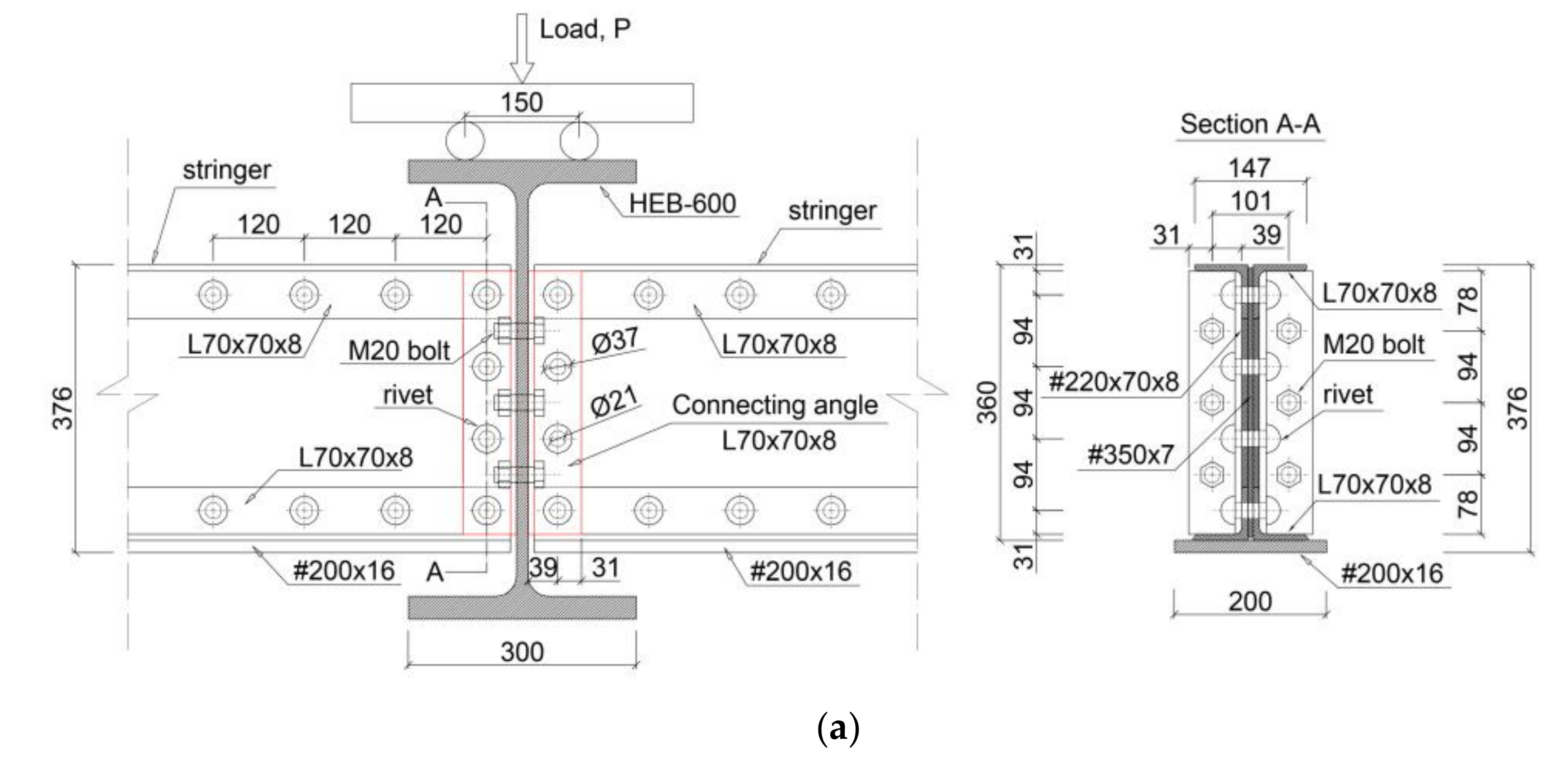
Each test specimen was built-up with two original stringers from Redondela bridge, connected by means of their original connecting angles to the web of an HEB-600 hot-rolled laminated S275 steel profile, that would correspond to the floor beam web in the bridge. The original floor beams could not be used for these tests as these elements remained in the bridge (only stringers with their riveted connecting angles were extracted from the bridge). The original cross-section of the stringer was composed of four flange angles L70 × 70 × 8 (top and bottom flanges) riveted to a web plate with a height of 350 mm and a thickness of 7 mm as shown in Figure 6a. The rivet sank was 21 mm in diameter, the rivet head was 37 mm diameter and the spacing between horizontal rivets (connecting the flange angles to the web plate) was 120 mm. During strengthening works in the past, a 200 mm width and 16 mm thickness steel plate was welded to original top flange angles, although the assembly of the test specimen was placed upside down with respect to the original position in the bridge and this welded plate appears at the bottom in Figure 6a. The connecting angles (to connect the stringer web to the floor beam web), which represent the fatigue-prone detail of interest in this study, were also L70 × 70 × 8 angles with a length of 344 mm, riveted with 21 mm diameter rivets to both stringer web (with 4 rivets) and floor beam web (with three rivets per angle). The vertical spacing between these rivets in the connecting angles was 94 mm and the gauge distance of the angle leg (distance between the center of rivet hole and the external face of angle leg) was 39 mm, as shown in Figure 6a. Because of the difficulty in replicating the riveting technique for these test specimens to obtain rivets with similar mechanical properties as the originals, DIN 933 M20 grade 6.8 carbon steel bolts were used for the connection of the angles to the HEB-600 profile web. These low-grade steel bolts were used to better approximate the strength of puddle iron rivets, compared to commonly used high-strength grade 8.8 bolts.

3.2. Materials Properties

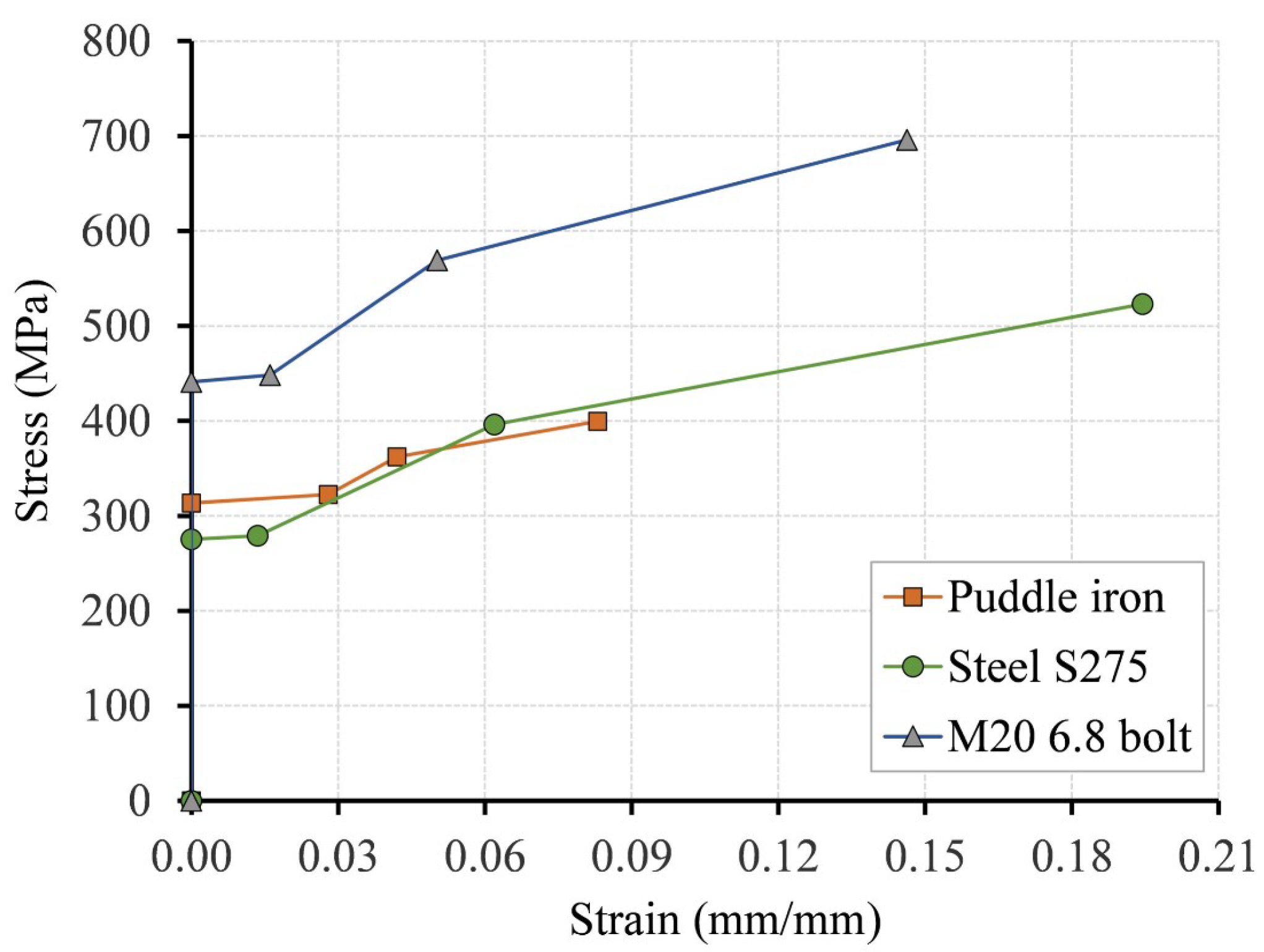
From tensile tests on puddle iron coupons tested according to UNE-EN 6892-1 [30], an average tensile modulus of elasticity, yield stress and tensile strength of 198 GPa, 313 MPa and 367 MPa were obtained, respectively [9]. Due to the difficulties in testing rivet specimens for their mechanical characterization, mechanical properties of rivets were assumed the same as used for puddle iron plates. Mechanical properties of S275 steel (for HEB-600 profile) and M20 grade 6.8 carbon steel bolts were assumed according to reference values in standards UNE-EN 10025-2 [31] and ISO 898-1:2013 [32], respectively. The mechanical properties of these metallic materials are listed in Table 3.

3.3. Test Set-Up and Instrumentation

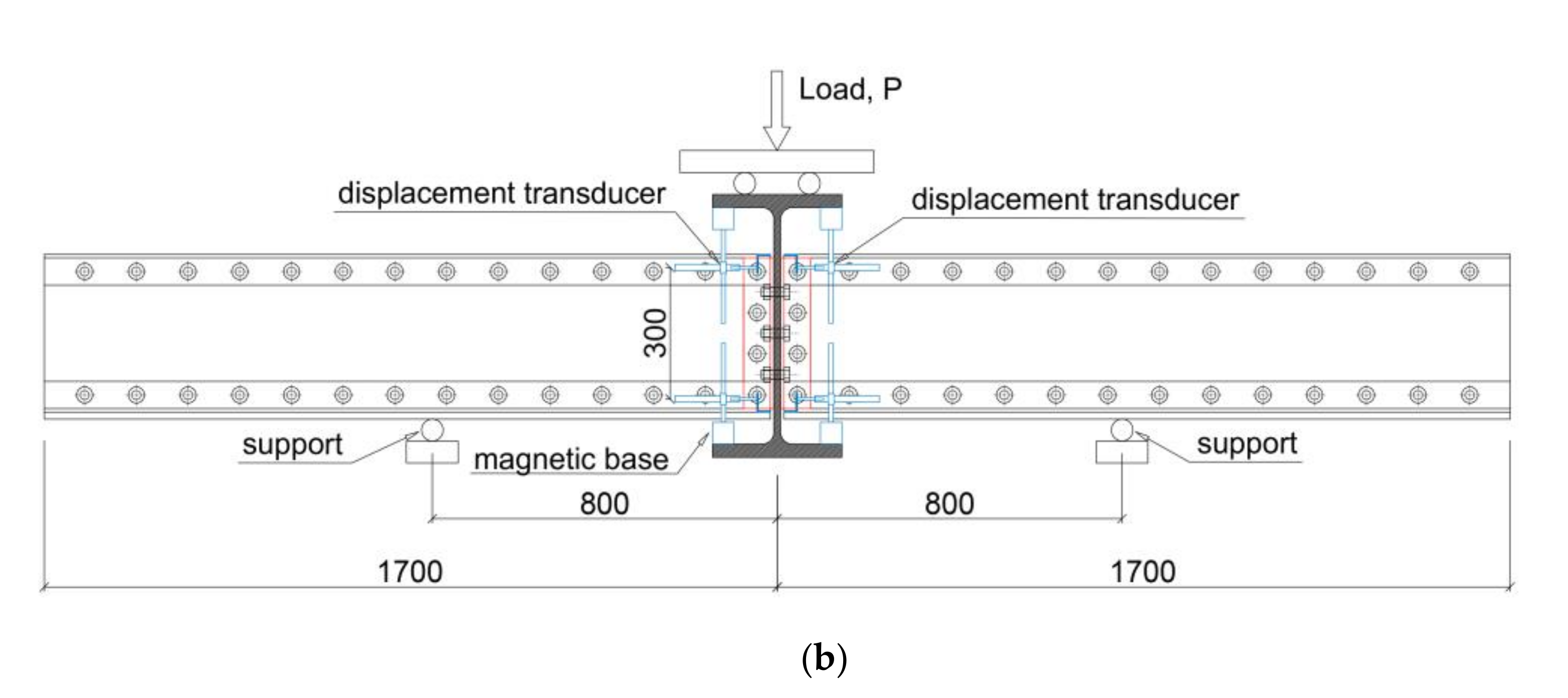
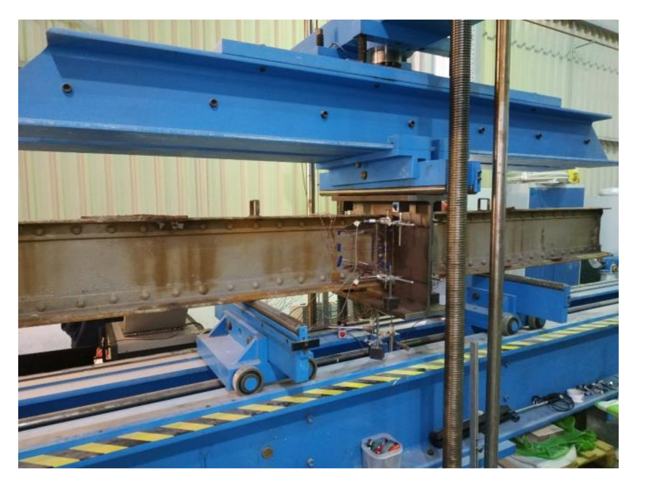
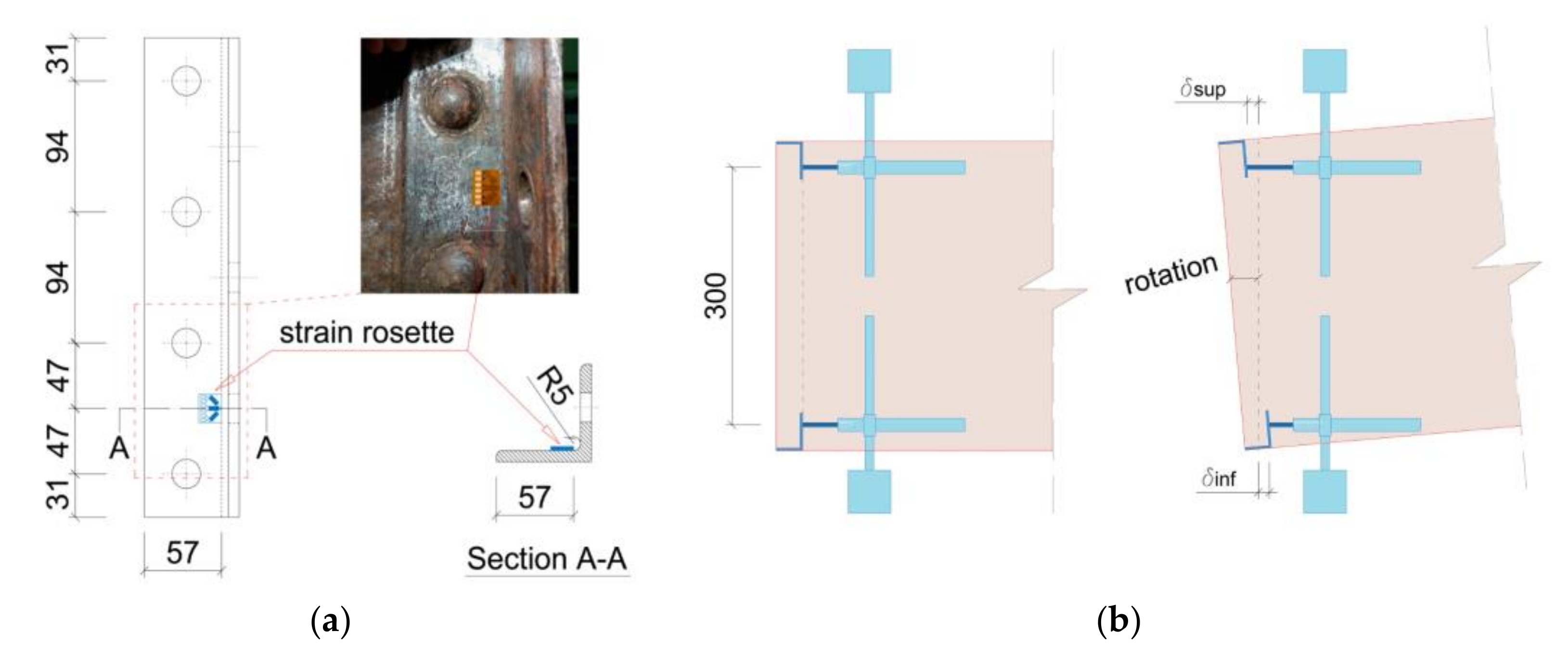
Each of the specimens was 3.4 m in length (double the length of cut stringers from the bridge, 1.70 m) and was simply supported on the rollers of the bending press machine at a span length of 1.60 m (to represent the distance between two consecutive point loads on UIC Load Model 71, Figure 4a). Vertical load was applied to the top flange of the HEB-600 profile from a Proeti bending press machine with a 500 kN load cell (Figure 7), with a loading rate of 150 N/s (load-controlled). To apply the same bending moment at the connection as in the bridge, the assembly of the test specimen was placed upside down with respect to the original position in the bridge (plate #200 × 16 was placed at the bottom, Figure 6a). In this way, the distortion-induced strains in the connecting angles due to bending moment would develop at the same location as they had in the bridge. To monitor these strains, a foil strain gauge rosette (3-axis strain gauge) was mounted on each connecting angle (fatigue-prone detail) of the stringer-floor beam connection specimen. Based on previous research works [4,33] strain rosettes were placed coincident with the bottom connecting bolt and immediately after the toe of the angle fillet (Figure 8a), close to the position where maximum principal (tensile) strain, which typically produces fatigue cracking in this detail, was expected to develop during testing.
To measure the rotation of the connection during test, displacements transducers were placed horizontally both at bottom and top of the connection (Figure 6b). These transducers were fixed by means of magnetic bases to the flanges of the HEB-600 profile, while the transducers ends were in contact with small angles welded to the bottom and top flanges of the stringer. To compute the rotation of the connection, the arc tangent of the quotient between the measured horizontal displacement increment (summation of bottom and top displacements in Figure 8b, δinf + δsup) and the vertical distance between the bottom and top measure points (300 mm) was obtained during testing.

4. Local FE Model of Stringer-Floor Beam Connection

4.1. Model Description

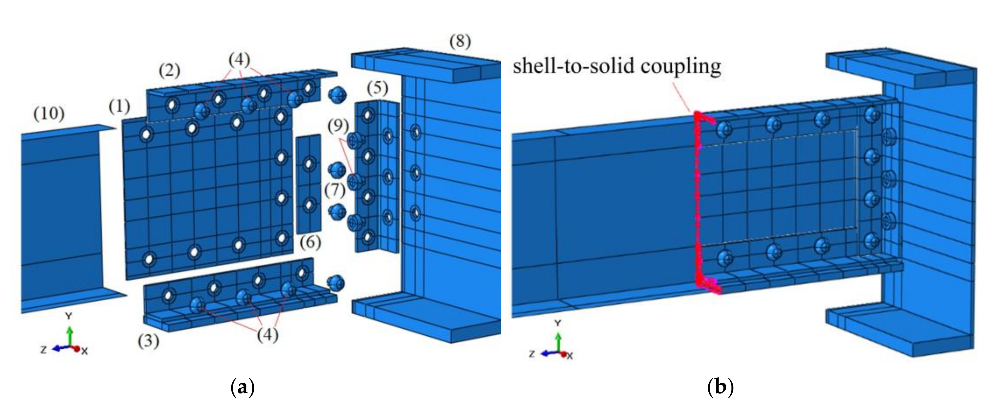
A 3D finite element analysis was performed using commercial FE-code Abaqus© v6.13 to obtain the moment-rotation curve for the stringer-floor beam connection. This numerical model was calibrated based on the laboratory test described in previous section. The 3D model was created by the assembly of nine solid parts (Figure 9a): stringer web (1), top flange (2), bottom flange (3) and rivets (4) to connect stringer flanges to web; connecting angle (5), mounting plate (6) and rivets (7) to connect angle to stringer; floor beam profile (8) and bolts (9) to connect angle to floor beam. All these parts were modelled as 3D deformable solids, meshed with eight-node first-order brick (hexahedral) elements enhanced with incompatible modes (C3D8I). The use of this element formulation is recommended for bending-dominated problems [34], because these elements are fully integrated (hourglass effect related to reduced integration elements C3D8R is avoided) with added internal degrees of freedom (incompatible deformation modes) eliminating the shear locking phenomena (presented with full integration elements C3D8). To reduce computation effort, a shell part modelled using first order (four-node) shell elements with reduced integration formulation (S4R) and enhanced hourglass control was used for the stringer (10) sufficiently far away from the riveted connecting angle, where high stress concentrations are not expected. A surface-based shell-to-solid coupling was used for the transition from the shell elements to the brick elements (Figure 9b), coupling the motion of the nodes along the edge of the shell elements to the motion of the nodes on the solid surface at the transition [35]. Mesh density was established by default mesh seed sizing controls, with a nominal element size of 10 mm for all solid parts, except for the connecting angle, where a higher density (element size of 3 mm) was considered. As recommended in [33,36], this finer mesh in the connecting angle was used to better capture the strain gradients close to the connecting angle fillet, where foil strain gauge rosettes were placed in testing specimens to measure strain during loading. This also results in 32 elements around the perimeter of rivets and bolts holes in the connecting angle, following the recommendations made in [5].
To prevent one model surface from penetrating another, contact interaction was explicitly defined for all potential contact surfaces. General contact, surface-to-surface formulation [35] was used to define contact for all allowable element faces and model entities, created in the initial analysis step and propagated to the rest of steps. Contact was defined by both normal and tangential interaction properties. Normal contact property was defined as “hard contact” that allowed surface separation after contact and tangential contact property was defined as friction “penalty” with an assumed coefficient of friction defined as 0.15 between the surfaces that are in contact.
To reduce the model computation effort, two boundary conditions were defined at surfaces of both symmetry planes of the laboratory specimen to reduce the model to a quarter. An anti-symmetry boundary condition about planes parallel to XZ plane (U1 = U3 = UR2 = 0) was assigned to mid-plane of floor beam HEB-600 profile web and a symmetry boundary condition about a plane parallel to YZ plane (U1 = UR2 = UR3 = 0) was defined for mid-plane of stringer web (Figure 10a). A displacement/rotation boundary condition was defined corresponding to the stringer support on the testing machine, to constrain all the movements and rotations at the support, except free movement along Z-axis and free rotation on X-axis (Figure 10b). To maintain all components assembled, an equivalent clamping stress was applied to all rivets and bolts to simulate pretension, assumed to be equal in all of them. All these boundary conditions were created in the second analysis step and were propagated to subsequent analysis steps. Based on a parametric study by the authors with different pretension values, it was obtained that pretension has marginal effect on rotational stiffness of the connection and strains in the connecting angle, as also previously reported [34,37], so a fixed value of σpret = 100 MPa is adopted in this work. This pretension is within the range values (between 50–200 MPa) of rivet pretension in field observations [5] and was also adopted by other authors for similar analysis [24]. This pretension was induced with a specified equivalent displacement applied to the face of the rivet/bolt shank at the cut coincident with symmetry planes (Figure 10b), being 0.0058 mm, 0.0099 mm and 0.0075 mm for stringer flanges rivets (4), connecting angle rivets (7) and bolts (9), respectively. These values were obtained according to Hooke’s Law using the following equation:
Δ L   =   L 0   σ p r e t E
where L0 is the initial length of rivet/bolt shank (in mm) that is prestressed; σpret is the rivet/bolt pretension (in MPa); and E is the modulus of elasticity of the rivet/bolt material (in MPa), being 198 GPa for the rivets and 210 GPa for the bolts. The initial length of rivet/bolt shank in the FE model (only half the length of bolt/rivet shank was modelled) was 11.50 mm, 19.60 mm and 15.75 mm for stringer flanges rivets (4), connecting angle rivets (7) and bolts (9), respectively. Finally, to simulate displacement-controlled loading of the specimen, a displacement boundary condition in negative Y direction (Figure 10b) with a maximum value of 12 mm was defined in the third, non-linear analysis step, which accounted for geometric nonlinearities associated with the displacements of the model. Compared to load-controlled, displacement-controlled loading improves numerical convergence, especially when large deformations are expected, as this was the case and is preferable to establish the initial contact of potential contact surfaces between the different parts of the model. The direct linear equation solver with full Newton solution technique was used, with automatic control of the increments size. A maximum number of increments allowed during the step was set equal to 100, an initial time increment of 10% of the total step time was provided and the minimum allowable time increment was adjusted to 10−9 (lower than default value 10−5 because plastic deformations were expected).
Metallic materials of the connection (puddle iron, steel S275 and M20 6.8 carbon steel bolts) were modelled using the quad-linear stress-strain (σ-ε) model in Equation (2) proposed by [38], which represents an elasto-plastic behavior with yield plateau and isotropic strain hardening. This model used only three basic mechanical parameters, modulus of elasticity E, yield stress fy and tensile strength fu of the material (Table 3), while the additional mechanical parameters to completely define the stress-strain curve were calculated by the following expressions, calibrated based on extensive tensile tests database [38]:
σ   =   { E ε f o r   ε     ε y f y f o r   ε y   <   ε     ε s h f y   +   E s h ε ε s h f o r   ε s h <   ε     C 1 ε u f C 1 ε u   +   f u f C 1 ε u ε u C 1 ε u   ε C 1 ε u f o r   C 1 ε u <   ε     ε u
where
ε u   =   0.6 1 f y f u     0.06
ε s h   =   0.1 f y f u 0.055 ,   0.015   ε s h     0.030
C 1   =   ε s h   +   0.25 ε u ε s h ε u
E s h   =   f u f y 0.4 ε u ε s h
As recommended in [39,40,41] for the definition of plastic behavior of metallic materials in finite element analysis when large deformations are expected, true stress-strain curves (based on the instantaneous cross-section area and gauge length) were used. For this purpose, engineering stress-strain curves (based on the original cross-section area and gauge length) obtained from Equation (2) were converted to true stresses and strains (Figure 11) according to the following expressions, the latter being used for the material definition in the local FE model:
σ t r u e   =   σ n o m   1   +   ε n o m
ε t r u e   =   l n   1   +   ε n o m

4.2. Calibration of Local FE Model

Due to the presence of large slag inclusions parallel to rolling direction that were generated during fabrication of puddle iron plates, yield stress fy is typically lower in the transversal direction [42,43]. Based on a previous study by the authors [9], a significant amount of longitudinal non-metallic inclusions was observed on micrographs of puddle iron plates from Redondela bridge. For this reason, anisotropic plasticity was assumed for the material modeling of the connecting angle, which is subjected to transverse tensile stresses especially at the angle fillet due to bending at the stringer-floor beam connection. For simplicity, only the connecting angle was modelled with anisotropic plasticity, as this was the region of interest in this analysis, where maximum strains were measured and where fatigue cracks were prone to appear. For this purpose, Hill anisotropic plasticity potential [35] was used for the connecting angle material, defining yield stress ratios Rij with respect to the reference yield stress fy in the longitudinal tensile direction (local material direction 1 corresponding to rolling direction during puddle iron plate fabrication). In this case, all yield stress ratios Rij, except R11 = 1.0 (local material direction 1 of connecting angle), were defined with a constant value Rij < 1.0 (reduction of yield stress in other directions than longitudinal). Since the quality of puddle iron produced during 19th century was not regulated and was difficult to control, it possibly contributed to the variability of its mechanical properties, not just between different bridges and manufacturers, but also even within the structural components of a single bridge produced by the same manufacturer [44]. For this reason, a parametric study was performed with different yield stress ratios Rij to obtain the value that best fitted experimental results.
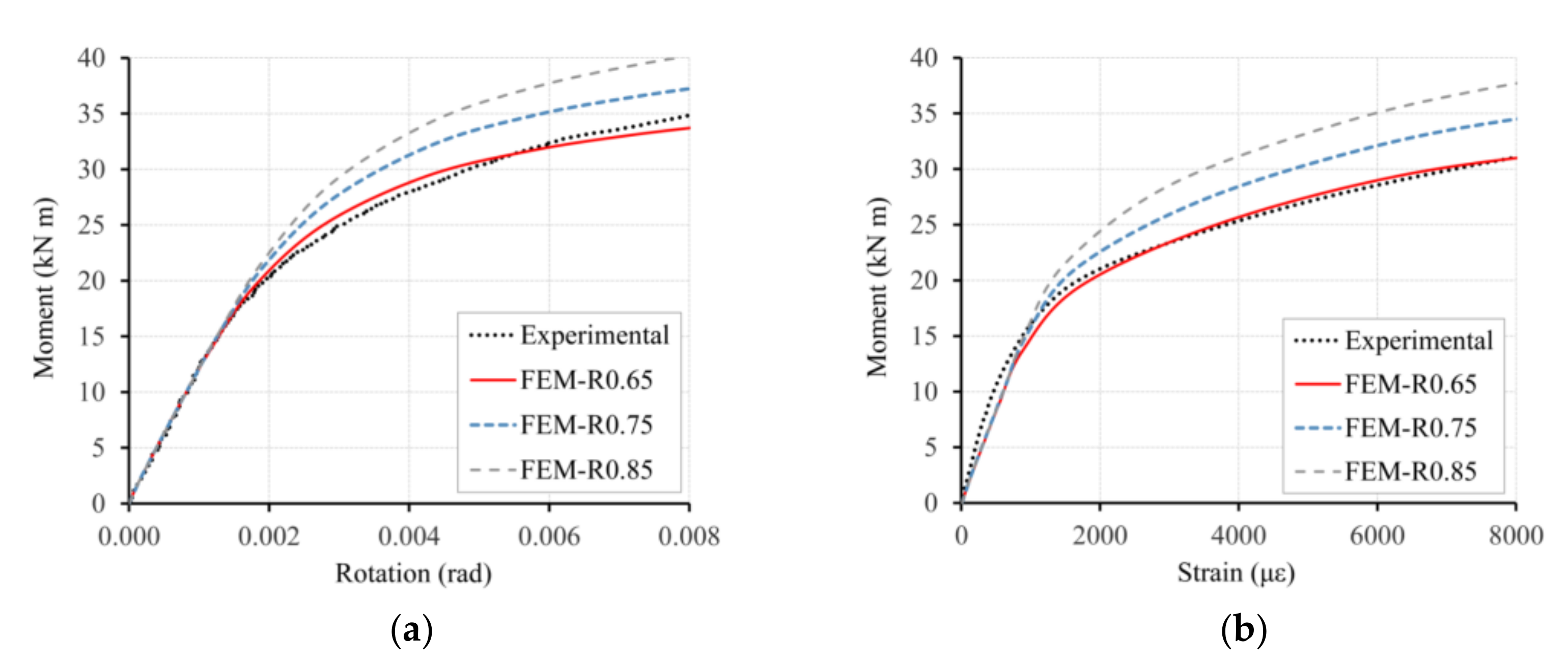
The moment-rotation behavior of the connection in the local numerical model is shown in Figure 12a, for different values of the yield stress ratio Rij (0.65, 0.75 and 0.85) labelled as FEM-R0.65, FEM-R0.75 and FEM-R0.85 in the legend, respectively. These curves were compared with the moment-rotation behavior in the non-strengthened tested specimen (obtained from average measured rotations from both sides of the connection) and it was observed that the curve FEM-R0.65 best fitted the experimental results, so the yield stress ratio Rij = 0.65 was used for the analysis.
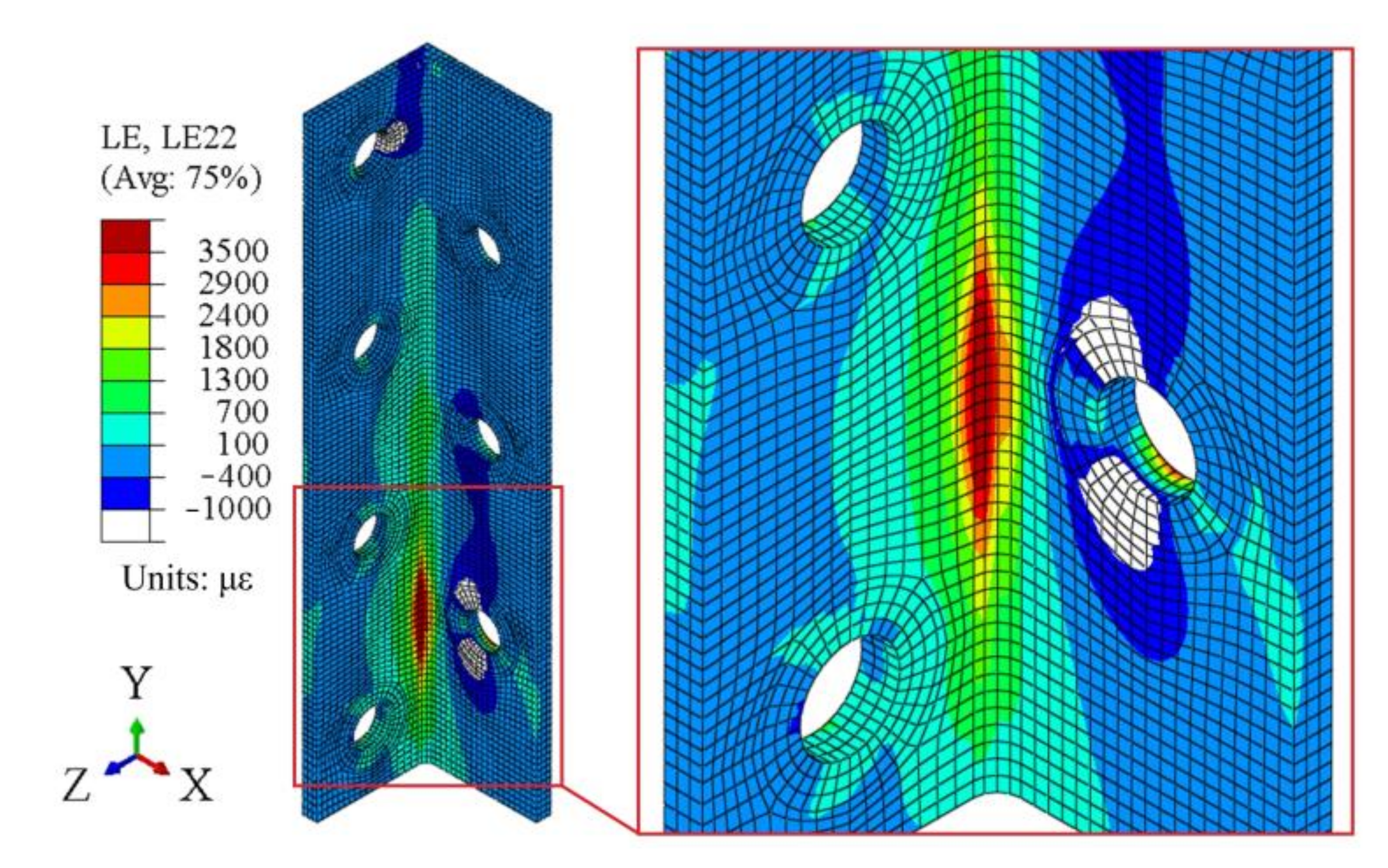
Due to the high strain gradient close to the angle fillet obtained from the local FE analysis (Figure 13), strain measurements were presumed to be very sensitive to strain gauge location, even if special care was taken during strain rosettes installation. For this reason, experimental values in Figure 12b were taken as the averaged measured strain values from the four monitored angles in the non-strengthened tested specimen and were compared with the numerical results in the local FE models, showing that the curve FEM-R0.65 best fitted the experimental results. Based on the analysis of strain rosette (3-axis strain gauge) measurements in the tested specimen, it was obtained that maximum (tensile) principal strain direction was oriented transversally (local 2 direction in the local FE model) to angle profile rolling direction (local 1 direction). This is also confirmed in the local FE analysis, as LE22 strains (logarithmic strains in the local 2 direction) were coincident with maximum (tensile) principal strains.
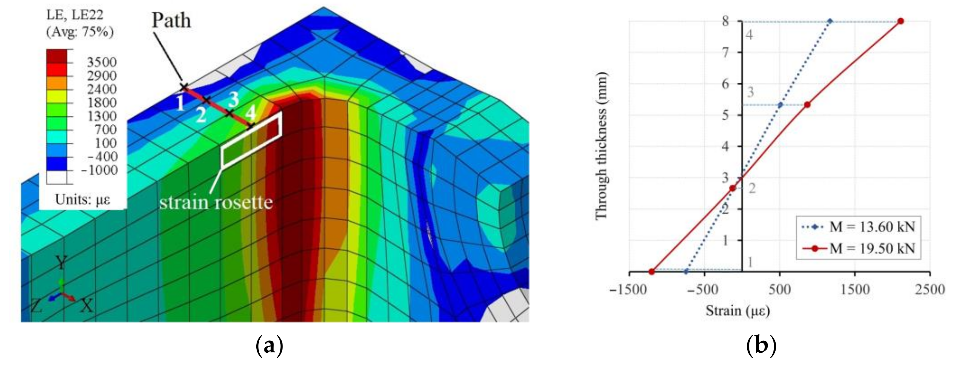
To confirm the out-of-plane bending deformation of the connecting angle, which typically leads to fatigue-crack initiation [5,33], the strains through the thickness of the angle were obtained at two different loading levels to see the evolution with increasing loads. For this purpose, the transversal logarithmic strains (LE22) along a path defined by four points (1, 2, 3 and 4 in Figure 14a) through the 8 mm thickness of the angle are represented in Figure 14b for bending moments 13.60 kNm and 19.50 kNm. From these curves, it was confirmed that the highest tensile strains developed on the outer face of the angle (where strain rosette was attached), while the inner face of the angle (in contact with the stringer web) remained in compression. This out-of-plane bending in this type of connections is found to be the cause of the development of high tensile strains in the outer face of the connecting angle close to the angle fillet, which could lead to the formation of fatigue cracks under cyclic loading, as previously reported in similar research works [5,33].
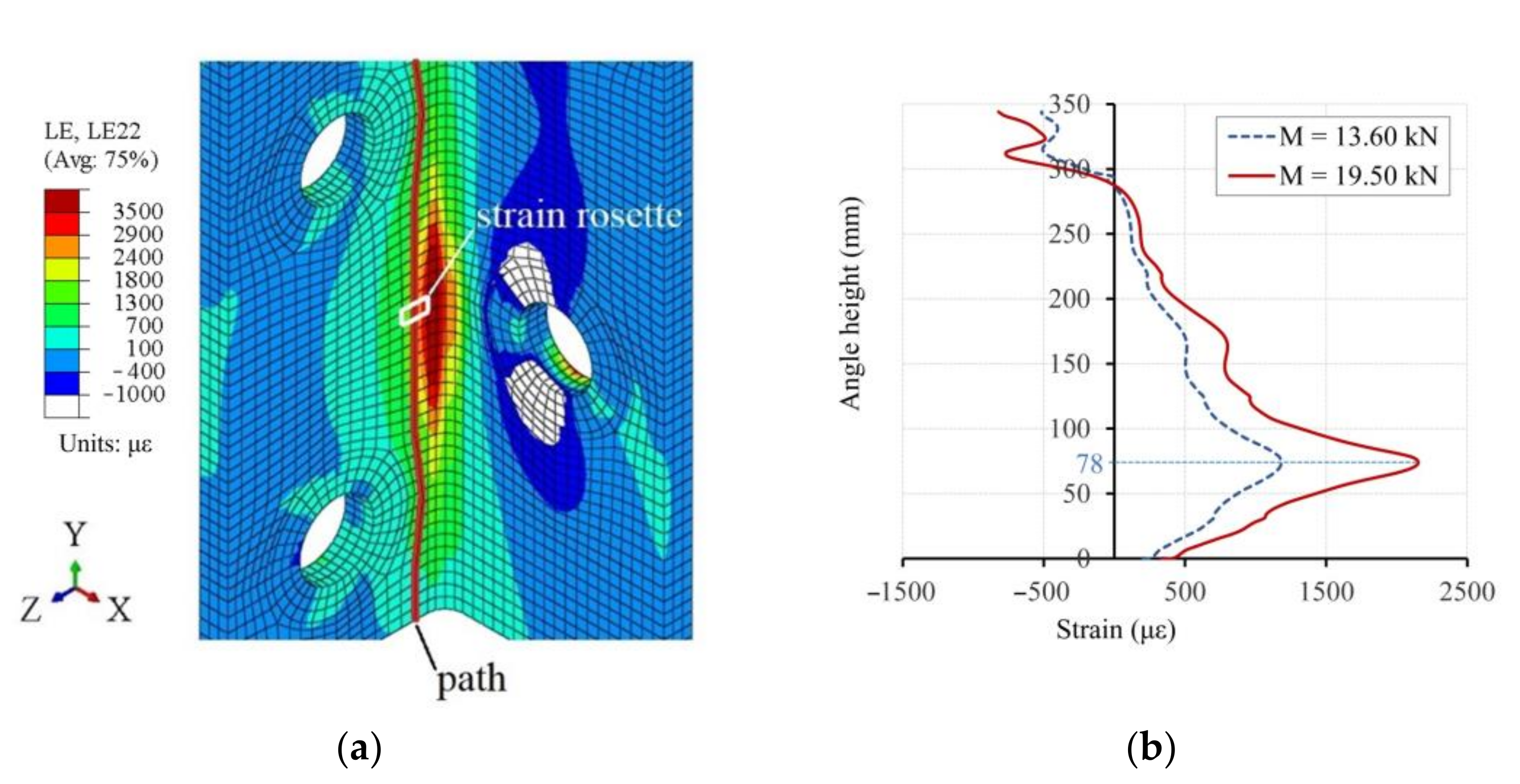
Similarly, a path along the height of the connecting angle, passing through the strain rosette location, was defined in Abaqus© visualization module (Figure 15a) and the results are presented in Figure 15b. In this case, the strains are obtained on the outer face of the connecting angle, where maximum tensile strains were reported in Figure 14. From the curves in Figure 15b, it is shown that the maximum tensile strain along the height of the connecting angle developed coincident with the angle cross-section corresponding to the axis of the bottom connecting bolt (cut in Figure 14a), located at 78 mm from the bottom edge of the angle (Figure 6a).

4.3. Results from Global-Local FE Models

As it can be obtained from Figure 12a, the initial slope of the moment-rotation curves (experimental and numerical FEM-R0.65) is constant up to approximately a bending moment of 15.00 kNm and a rotation of 0.0013 rad, corresponding to a rotational stiffness K = 11,540 kNm/rad. This initial value of rotational stiffness K was introduced in the global FE model of the bridge to obtain the maximum moment at stringer-floor beam connections due to train loading. By an iterative process, convergence was obtained between the introduced rotational stiffness in the global FE model and the corresponding K in the local FE model (FEM-R0.65 moment-rotation curve in Figure 12a) for the resulting moment at the connection in the global model, until an error less than 1% was achieved.
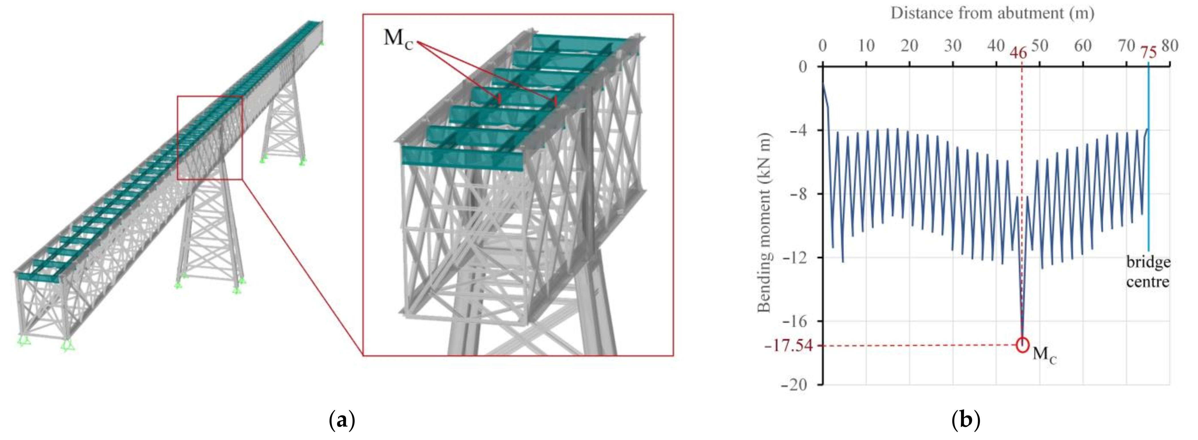
With this procedure, the maximum bending moment MC at stringer-floor beam connections (Figure 16) due to the train loads (Figure 4) applied to the global FE model of the bridge were obtained and shown in Table 4. As an example, the bending moment at the connections along half-length of the bridge is represented in Figure 16b for the case of UIC Load Model 71. It can be clearly observed that the maximum bending moment developed at the stringer-floor beam connection in correspondence with the intermediate bridge piers. For these bending moments, the corresponding maximum (tensile) principal strain at the measuring point in the connecting angle (strain rosette location in Figure 8a) was computed from the local FE model of the connection (FEM-R0.65 curve in Figure 12b) and the results are shown in Table 4 for each train load model.
The bending moment at the connection corresponding to permanent loads (dead load + track) was 1.32 kNm, which corresponds to a maximum (tensile) strain at the measuring point in the connecting angle of 81 μm, equal to a tensile stress of 16.04 MPa. This stress value will be considered as the constant minimum stress σmin in the cyclic loading of the connection for the fatigue analysis in next section.

5. Design of CFRP Strengthening to Prevent Fatigue Crack Initiation

5.1. Fatigue Criteria: CLD Method

Cyclic loading with constant amplitude refers to a sinusoidal loading pattern with a constant stress range defined by the difference between a constant maximum stress σmax and a constant minimum stress σmin, Δσ = σmax − σmin. For this cyclic stress pattern, the constant mean stress σm and the constant alternating stress amplitude σa (half the stress range) are determined by:
σ m   =   σ m a x   +   σ m i n 2
σ a   =   σ m a x     σ m i n 2
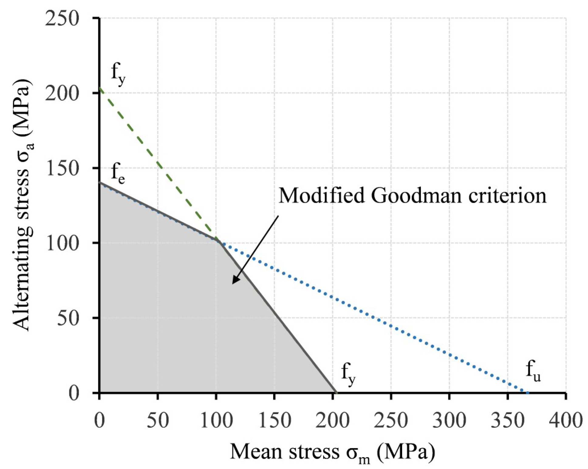
The combined effect of mean stress σm and alternating stress σa on the fatigue life of metallic members can be expressed by a fatigue failure criterion. This failure criterion can be represented in a constant fatigue-life diagram by a curve defined by combinations of mean and alternating stresses σma with the same fatigue live [45]. In the present work, the modified Goodman fatigue failure criterion was used, because several studies have shown it is conservative enough to prevent fatigue failure in ductile metals and can be used for design purposes [19,46]. This failure criterion is defined in the constant fatigue-life diagram with two straight lines. The first line is defined by limiting both the maximum mean stress and the maximum alternating stress with the yield strength of the material, joining points σm = fy in the abscissa axis and σa = fy in the ordinate axis (dashed line in Figure 17). The second line (dotted line in Figure 17) passes through two representative points. The first point is the maximum mean stress (corresponding to zero alternating stress) defined by the material tensile strength, σm = fu. The second point coincides with the alternating stress amplitude corresponding to zero mean stress, prescribed as the fatigue endurance limit, σa = fe, which was obtained from fatigue tests of puddle iron specimens from Redondela bridge, with a value of fe = 140 MPa. The criterion for the first line is expressed in Equation (11), while the criterion for the second line is expressed in Equation (12):
σ m f y +   σ a f y   =   1
σ m f u   +   σ a f E   =   1
If a combination of stresses σm and σa represented in the constant fatigue-life diagram remains outside the region limited by the fatigue failure criterion solid lines (shaded region in Figure 17), the metallic member has finite fatigue life. Otherwise, combinations of stresses σma that fall inside this region are assumed to be safe from fatigue crack initiation and therefore have infinite fatigue life (N = ∞).
For a given applied cyclic loading with a constant stress range Δσ = σmax − σmin in a metallic member, the application of a CFRP strengthening system changes this stress range for the same cyclic loading, which results in variable-amplitude fatigue loading if stress ranges before and after strengthening are considered. To determine the accumulated damage due to variable-amplitude fatigue loading (before and after strengthening), the Palmgren–Miner linear damage accumulation rule in Equation (13) can be used [19]:
D   =     n i N i   =   D bs   +   D as   =     n i bs N i bs   +     n i as N i as   =     =     n i bs N i bs   <   1
where D is the overall accumulated damage, Ni and ni are the number of cycles to failure and the applied number of cycles both at stress level σi, respectively. Superscripts ‘bs’ and ‘as’ refer to ‘before strengthening’ and ‘after strengthening’, respectively. Because the CFRP strengthening is performed prior to crack initiation (visual inspections confirmed that there were no fatigue cracks in the connecting angles of the original stringers), accumulated damage before strengthening can be assumed to be lower than unity (Dbs < 1). Moreover, if the applied CFRP strengthening system is sufficient to shift the stresses combination σma into the infinite fatigue life region in the constant fatigue-life diagram, it can be considered that the number of cycles to fatigue failure after strengthening is infinite, Nias = ∞, so accumulated damage after strengthening can be assumed to remain approximately equal to zero (Das ≈ 0). As a result, based on the Palmgren-Miner rule in Equation (13), accumulated damage will be lower than unity, so fatigue failure will not occur.

5.2. CFRP Design by Local FE Model and CLD Method

By applying the CFRP strengthening to the fatigue-prone detail, both the mean stress and the alternating stress amplitude can be reduced so that these stresses can be shifted below the fatigue failure criterion curve in the constant fatigue-life diagram. This shift from the “at risk” finite life region to the “safe” infinite life region means that fatigue crack initiation would be prevented.
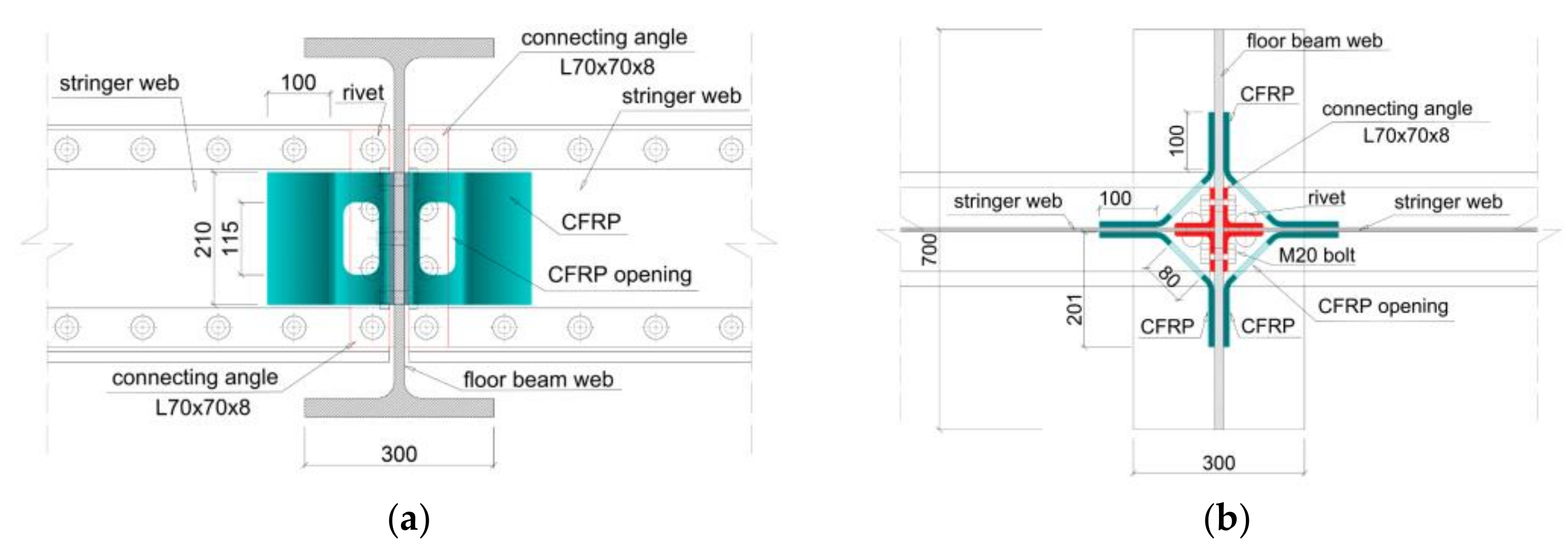
The designed strengthening system consisted of four CFRP angles adhesively-bonded both to the stringers and HEB-600 profile webs. This strengthening aimed to reduce the stress level in the puddle iron connecting angles and consequently to increase fatigue life of this fatigue-prone detail. The CFRP angle was 210 mm high so that it can be bonded to the stringer web area that remained between top and bottom stringer riveted flanges. Based on a previous study by the authors with CFRP-metal double-strap joints bonded with the same epoxy adhesive used in this study [6,9], both flanges of the CFRP angle were designed with a width of 100 mm, as it is considered above the effective bond length for these adhesive joints. The angled geometry of this system was needed to avoid the connecting riveted angles (Figure 18) and an opening cut (80 mm × 115 mm) in the CFRP angles was needed to allow the inspection of the detail after strengthening application, which is usually a requirement from bridge owners.
The CFRP strengthening system was included in the local FE model of the stringer-floor beam connection described in previous sections. This CFRP laminate was modeled in Abaqus© as a conventional shell composite layup with a 3D deformable shell part, using first order (four-node) thick shell elements with reduced integration formulation (S4R) and enhanced hourglass control. The composite layup was defined as a sequence of ordered stacked unidirectional carbon fiber/epoxy plies. For each ply (lamina) in the laminate stacking sequence, the orthotropic elastic properties under plane stress conditions (E1, E2, ν12, G12, G13 and G23 presented in Table 5), the thickness and the fiber orientation (angle relative to the layup reference orientation) were defined. The element orientation was defined using the discrete method [35], defining a normal axis (perpendicular to the shell surface) and a primary axis direction, defined as the bottom contour of the CFRP part, as shown in Figure 19a, with local 1 direction in the elements corresponding to the fiber direction.
In addition, the damage initiation criteria for fiber-reinforced composites based on Hashin’s theory [47] was included in the material definition for the prediction of the onset of degradation at any material point, using the strength properties in Table 6. As the CFRP is used for fatigue strengthening, no damage initiation mechanisms should occur for fatigue limit state (all plies in the CFRP must remain below damage initiation for fatigue loading), as it was confirmed in the numerical model. Accordingly, a perfect bond was assumed between the CFRP and the metallic surfaces (no adhesive failure under service fatigue loads), so a tie constraint (Figure 19b) was defined in the model between bonded surfaces (CFRP-stringer web and CFRP-floor beam web).
For the design of the CFRP laminate, the materials used were Torayca® T700 carbon fiber (CF1), Pyrofil™ HR40 carbon fiber (CF2) and a two-part epoxy resin Araldite® LY 1568/Aradur® 3489. The uniaxial tensile mechanical properties of CFRP unidirectional laminae (CF1 and CF2) were obtained experimentally and were reported in [6,9]. The remaining orthotropic stiffness and strength properties used for the material definition of CFRP laminates in the local FE model were obtained from micromechanics [48] and are listed in Table 5 and Table 6.
In the previous Table 5 and Table 6, E1 is the longitudinal (fiber direction) stiffness of the lamina; E2 is the transversal (direction perpendicular to fibers) stiffness; ν12 is the in-plane Poisson ratio; G12 is the in-plane shear modulus; and G13 and G23 are the interlaminar shear modulus. F1t is the longitudinal tensile strength; F1c is the longitudinal compressive strength; F2t is the transverse tensile strength; F2c is the transverse compressive strength; S1 is the longitudinal shear strength; S2 is the transverse shear strength.
Three different stacking sequences (arrangements of plies with different fiber orientations) for the definition of the CFRP laminate layout (Table 7) were numerically evaluated, so a proper configuration could be obtained to reduce the strain levels in the connecting angle to shift from the unsafe zone to the safe zone in the constant fatigue-life diagram. The selection of the number of plies and fiber orientations was based on two considerations. First, the stacking sequence of the CFRP laminate was defined with unidirectional carbon fiber/epoxy plies oriented in different directions to obtain a multi-axial quasi-isotropic laminate, which is preferable for multi-axial stress states. Second, the commercially available carbon fiber fabrics weights determined each ply thickness, so laminate thickness could be increased by discrete increments. A thickness of 0.35 mm was considered for each ply with fiber orientation +45° or –45°, while a thickness of 0.44 mm was used for each 0° or 90° ply with carbon fiber CF1. For each ply at 0° with CF2, the thickness was 0.32 mm.
For the definition of stacking sequences in Table 7, the number in the subscript corresponds to the number of consecutive plies with the same fiber orientation and same carbon fiber type (CF1 or CF2). The subscript ‘s’ refers to ‘symmetric laminate’ (all plies are repeated symmetrically with respect to the last ply in the brackets to form the full stacking sequence). All plies used carbon fiber CF1, except the plies at the symmetry plane of the laminate (plies in italics in Table 7), which used stiffer carbon fiber CF2 to increase the axial stiffness of the CFRP angles.
Based on the maximum principal strains in the connecting angle obtained from the FE local models, the mean stress σm and alternating stress amplitude σa are computed (Table 8) according to Equations (9) and (10), respectively, adopting a constant minimum stress σmin = 16.04 MPa in the connection corresponding to permanent loads on the bridge. These stresses combinations σma are represented in the constant fatigue life diagrams in Figure 20 for the train load models considered in this study, for the case of non-strengthened specimen. Similarly, σma stresses corresponding to the connection strengthened with the laminates in Table 7 are represented in the constant fatigue-life diagram for both the bending moment at the connection for UIC 71 (Figure 20a) and S335 (Figure 20b) train loads. It was not represented for Spanish Standard 1902 because the non-strengthened case was already in the safe region. Based on the results of this analysis, the stacking sequence corresponding to laminate L3 was the one that shifted the combination of mean stress and alternating stress amplitude inside the infinite fatigue-life region in the constant fatigue-life diagram for the most demanding situation, associated to load model UIC 71 (Figure 20a).
In the local FE model of the connection CFRP-strengthened with Laminate L3, the principal stresses in the different plies were evaluated for a bending moment of 19.50 kNm in the connection, 10% higher than the maximum bending moment corresponding to UIC Load Model 71 (17.54 kNm) to be on the safe side (safety factor of 1.10). It was obtained that the most loaded plies were the ones at the symmetry plane of the laminate (plies in italics in Table 7), which used stiffer carbon fiber CF2. For this ply (number 13 in the stacking sequence), the principal stresses are presented in Figure 21, showing tensile stresses at the bottom part of the CFRP angle while compression stresses at the top part, in agreement with an in-plane bending of the CFRP angle.
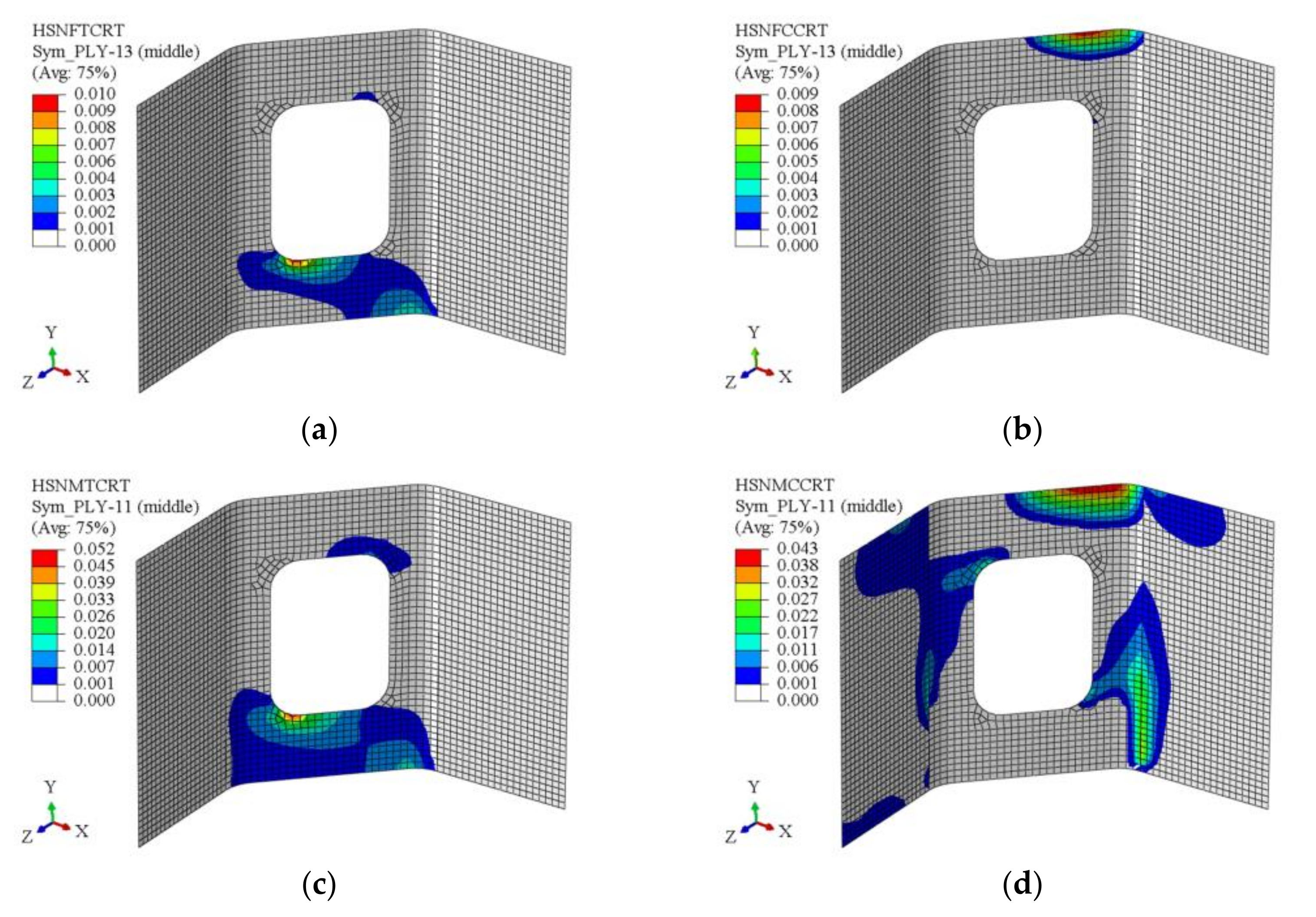
To confirm that no damage initiation occurred at any ply in the CFRP Laminate L3 for this bending moment of 19.50 kNm, the values for output variables related specifically to damage initiation criteria (based on Hashin’s theory [47]) were obtained. These variables take into account four different damage initiation mechanisms [35]: fiber tension (HSNFTCRT), fiber compression (HSNFCCRT), matrix tension (HSNMTCRT) and matrix compression (HSNMCCRT). For the variables above, a value that is less than 1.00 indicates that the criterion has not been satisfied (no damage initiation), while a value of 1.00 or higher indicates that the criterion has been satisfied (damage initiation). Fiber-related damages are more prone to occur at ply 13, while matrix-related damages would develop at ply 11. From the results in Figure 22, it was verified that no damage initiation mechanisms would occur for the maximum bending moment in the connection corresponding to service loading.

5.3. Experimental Validation of CFRP Strengthening

To confirm the effects of the proposed strengthening method (CFRP laminate L3) in reducing stress range in the fatigue-prone detail of stringer-floor beam connection, a specimen with original stringers from Redondela bridge and strengthened with CFRP angles was fabricated and tested under the same loading conditions and with the same test set-up and monitoring as non-strengthened specimen.
The CFRP strengthening angles corresponding to laminate L3 (Table 7) were fabricated by resin infusion, which consisted of placing the dry carbon fiber fabrics on an open metal mold, covering them with a flexible membrane (vacuum bag) that was sealed around the perimeter of the mold. Next, vacuum was applied inside the bag, so the resin flowed into the fabrics, impregnating them. After resin infusion, the piece was cured at 80 °C during 4 h, according to resin manufacturer recommendations. Once the resin cured and the piece solidified, the piece was removed from the mold and then cut to obtain the final dimensions needed for its installation in the connection to be strengthened.
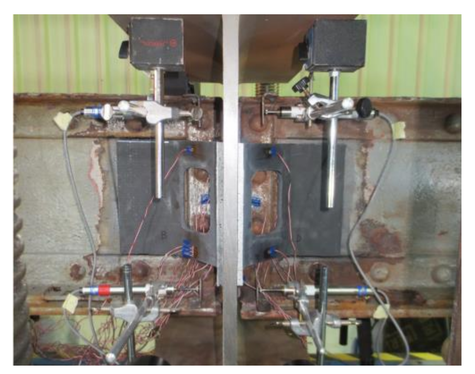
Before the installation of the CFRP strengthening system, the metallic surfaces were sandblasted to obtain a clean and rough surface (Figure 23a) for a proper adhesion, as this is the best surface preparation for these adhesive joints to metals [6,49]. After sandblasting, dust or particles were blown off the surface with clean and dry compressed air. Once metallic surfaces were ready (clean and dry), epoxy adhesive Araldite® 2031 was spread with a gun over the surfaces of the CFRP angles, which were previously cleaned with alcohol to eliminate dust, grease or other contaminants on the CFRP surface. Finally, the four CFRP angles were positioned on the connection and pressure was applied until the excess of adhesive flowed out to assure a proper bonding (Figure 23b). To maintain the CFRP strengthening angles in the right positions, sergeants were used to fix and hold the pieces in a firm and controlled position during adhesive hardening. According to manufacturer recommendations, adhesive was cured at 50 °C during 16 h. The tested specimen with CFRP strengthening angles is presented in Figure 24.
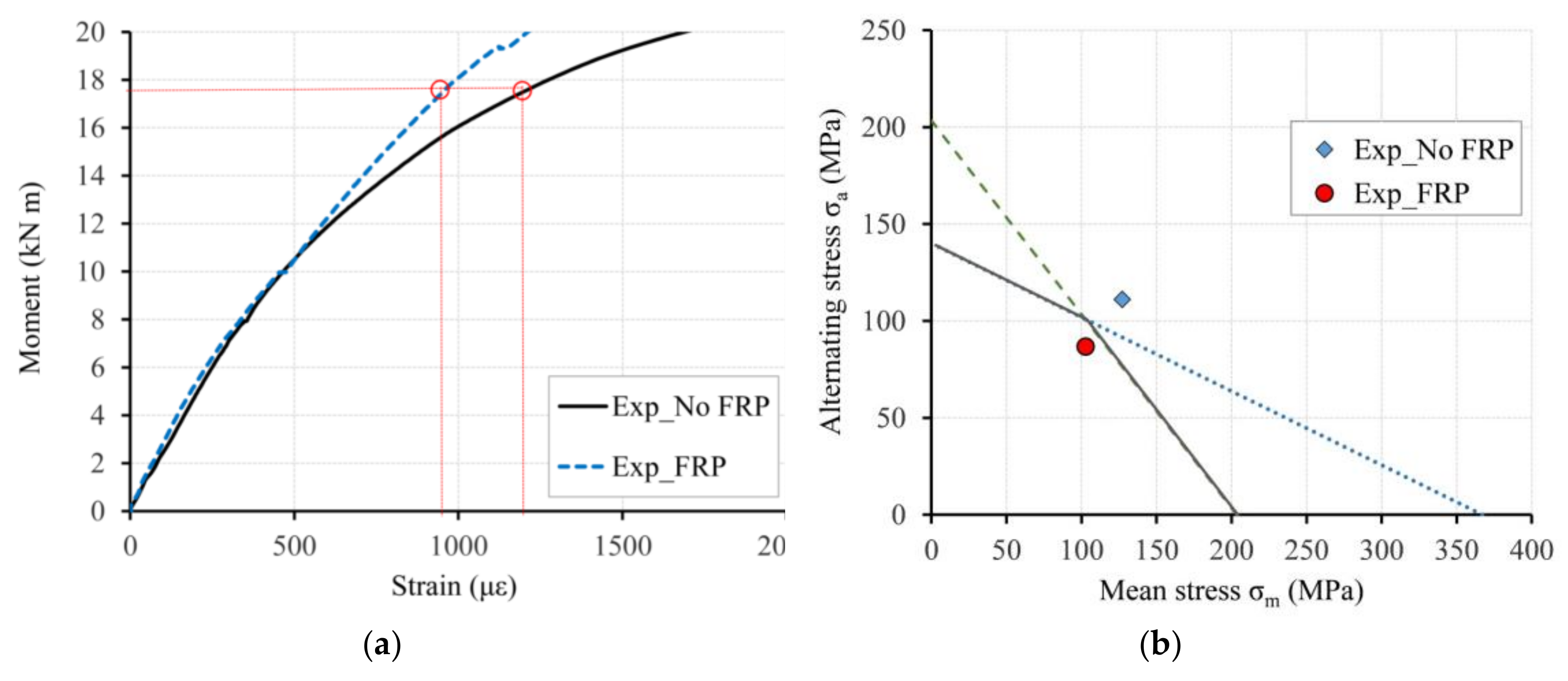
The results of the CFRP-strengthened connection test were compared with those of the non-strengthened one, so that the effects of the CFRP strengthening system can be assessed in terms of the reduction in the strain level (Figure 25a) at the fatigue-prone detail (riveted end-connecting angles) at the toe of the angle fillet. The graphs clearly show how the value of the maximum (tensile) principal strain decreased in the case of using the CFRP strengthening, for the same value of bending moment in the connection, compared to the non-strengthened case. For the value of bending moment 17.54 kN m (corresponding to load model UIC 71), the strain was reduced from 1203 με to 957 με (a reduction of 20.42%), when the CFRP strengthening was applied. Adopting a minimum tensile stress of 16.04 MPa, the corresponding mean stress σm and alternating stress amplitude σa were computed according to Equations (9) and (10), respectively, for both non-strengthened and strengthened specimens and represented in the constant fatigue-life diagram in Figure 25b. These results show that the use of this CFRP strengthening system can reduce the distortion-induced deformation in the connecting puddle iron angles, avoiding fatigue crack initiation in this detail and consequently, increasing its fatigue life.

6. Discussion

The maximum bending moments MC at stringer-floor beam connections, obtained from the global numerical model of the bridge, were 17.54 kNm, 10.64 kNm and 15.19 kNm for UIC 71, Spanish Standard 1902 and Renfe S335 train load models, respectively (Table 4). For these bending moments, the corresponding maximum (tensile) principal strains at the toe of the angle fillet (coincident with strain rosette location in laboratory specimens), computed from the local FE model of the non-strengthened connection, were 1439 με, 669 με and 1103 με, respectively (Table 4). Adopting a tensile modulus of 198 GPa for the puddle iron angles (Table 3), these tensile strains correspond to maximum tensile stresses of 284.92 MPa, 132.46 MPa and 218.39 MPa, respectively. The bending moment at the stringer-floor beam connections attributable to permanent loads on the bridge was 1.32 kNm, which corresponds, in the local FE model of the non-strengthened connection, to a maximum (tensile) principal strain at the measuring point in the connecting angle of 81 με, equal to a tensile stress of 16.04 MPa. Considering this stress value as the minimum stress σmin in the cyclic loading of the connection for the fatigue analysis, the corresponding mean stress σm and alternating stress amplitude σa were computed according to Equations (9) and (10), respectively. From Table 8, for the non-strengthened connection in the local FE model, it was obtained a mean stress of 150.48 MPa, 74.25 MPa and 117.22 MPa for UIC 71, Spanish Standard 1902 and Renfe S335 train load models, respectively. Similarly, an alternating stress amplitude of 134.44 MPa, 58.21 MPa and 101.18 MPa was computed, respectively, for these train loads (Table 8). These combinations of mean stress and alternating stress amplitude were represented in the constant fatigue-life diagrams (CLD) of Figure 20 and it is clearly observed that the connecting angle is prone to fatigue crack initiation for train load models UIC 71 and Renfe S335 (stresses combinations σma remain outside the infinite fatigue-life “safe” region). However, for the train load model Spanish Standard 1902, stresses are in the safe region, so an infinite fatigue life would be expected for this case.
For the design of a proper CFRP strengthening system that could shift these stresses from the finite fatigue-life region to the safe region in the constant fatigue-life diagram, three different CFRP laminates were numerically evaluated in the local FE model of the connection (Table 7). For each CFRP strengthening (L1, L2 and L3), the corresponding maximum (tensile) principal strains at the toe of the puddle iron angle fillet were obtained from the local FE models for bending moments at the connection for both UIC 71 (17.54 kNm) and S335 (15.19 kNm) train loads. For UIC 71 train load, these strains were 1154 με, 1065 με and 999 με for strengthened connection with laminate L1, L2 and L3, respectively, and correspond to maximum tensile stresses of 228.49 MPa, 210.87 MPa and 197.80 MPa, respectively. In case of Renfe S335 train load, strain values were 906 με, 851 με and 789 με for strengthened connection with laminate L1, L2 and L3, respectively, and correspond to maximum tensile stresses of 179.39 MPa, 168.50 MPa and 156.22 MPa, respectively. Based on these maximum tensile stresses and adopting a minimum tensile stress of 16.04 MPa, the corresponding mean stress σm and alternating stress amplitude σa were computed for each strengthening case. From Table 8, it can be obtained that the mean stress for UIC 71 train load decreased from 150.48 MPa (non-strengthened connection) to 122.27 MPa (18.75%), 113.46 MPa (24.60%) and 106.92 MPa (28.95%) when laminates L1, L2 or L3, respectively, were considered in the local FE model (strengthened connection). For the same train load, the alternating stress amplitude was reduced from 134.44 MPa (non-strengthened connection) to 106.23 MPa (20.98%), 97.42 MPa (27.54%) and 90.88 MPa (32.40%) for laminates L1, L2 or L3, respectively. Based on the results of this analysis, laminate L3 was the one that shifted the combination of mean stress and alternating stress amplitude inside the infinite fatigue-life region in the constant fatigue-life diagram for the most demanding situation, associated to load model UIC 71 (Figure 20a).
To confirm the effects of the CFRP strengthening with laminate L3 in reducing stress range in the fatigue-prone detail of stringer-floor beam connection obtained from the FE model, a specimen with original stringers from Redondela bridge and strengthened with this CFRP laminate was tested and results are compared with non-strengthened tested specimen. For a bending moment of 17.54 kNm in the tested specimens (corresponding to the maximum bending moment MC for UIC 71 train load), the maximum (tensile) principal strain at the toe of the angle fillet was reduced from 1203 με to 957 με (a reduction of 20.45%) when the CFRP strengthening was applied to the connection. Based on these strain measurements in the experimental tests and adopting a minimum tensile stress of 16.4 MPa (corresponding to permanent loads on the bridge) the related mean stress σm and alternating stress amplitude σa were computed. From Table 9, it can be obtained that the mean stress decreased from 127.12 MPa to 102.76 MPa (19.16%) and the alternating stress amplitude reduced from 111.08 MPa to 86.72 MPa (21.93%), when the connection is CFRP-strengthened, compared with the non-strengthened tested specimen. As shown in Figure 25b, this reduction in the mean and alternating stresses is enough to shift the stresses combination σma from the unsafe region into the infinite fatigue life region in the constant fatigue-life diagram. These results show that the use of this CFRP strengthening system can reduce the distortion-induced deformation in the connecting puddle iron angles, avoiding fatigue crack initiation in this detail and, consequently, increasing its fatigue life.
Although the stress reduction achieved in this particular case is lower than the 40% obtained with the prestressed CFRP rod system in [18] for the strengthening of stringer-floor beam connections, the CFRP adhesively-bonded system proposed in the present work (easier to be installed) could result in a promising solution for field applications.

7. Conclusions

A global finite element analysis of a 19th century riveted railway bridge made of puddle iron was performed to obtain the minimum and maximum bending moments at stringer-floor beam connections due to train loadings. The maximum (tensile) principal strains in the riveted connecting angles corresponding to these bending moments were obtained from a local FE model of the connection calibrated with the experimental results of a laboratory specimen fabricated with original stringers dismantled from the bridge. Based on this local FE analysis, it was observed that the maximum (tensile) principal strain, which typically produces fatigue crack initiation, was located at the fillet region of the connecting angle and was oriented transversally to rolling direction, which was also confirmed in the tested specimen. From the numerical analysis of the strains through the thickness of the puddle iron angle, it was confirmed that the highest tensile strains developed on the outer face of the angle (where strain rosette was attached in laboratory specimens), while the inner face of the angle (in contact with the stringer web) remained in compression. This out-of-plane bending of the angle leg, typical in this type of connections, was found to be the cause of the development of high tensile strains in the outer face of the connecting angle close to the angle fillet, which could lead to the formation of fatigue cracks under cyclic loading.
To better approximate the expected non-linear moment-rotation behavior of the stringer-floor beam connection in the local FE model, metallic materials were modelled using an elasto-plastic constitutive model with yield plateau and isotropic strain hardening. Due to the anisotropic nature of puddle iron profiles, the connecting angle, which was subjected to transverse tensile stresses especially at the angle fillet due to bending at the stringer-floor beam connection, was modelled using Hill anisotropic plasticity potential. A parametric study was performed in the local FE model with different yield stress ratios Rij (0.65, 0.75 and 0.85), obtaining that the value Rij = 0.65 in the transverse direction was the one that best fitted experimental results.
The analysis of the global-local FE models under the passage of train loadings UIC 71 and Renfe S335 showed that the connecting angles were prone to fatigue crack initiation close to the angle fillet. This was confirmed as the combination of mean stress and alternating stress amplitude in the angle fillet (150.48 MPa and 134.44 MPa, respectively, for UIC71 train load and 117.22 MPa and 101.18 MPa, respectively, for Renfe S335 train load) remained outside the infinite fatigue-life region delimited by the modified Goodman fatigue failure criterion in a constant fatigue-life diagram.
An adhesively-bonded CFRP system was designed for the fatigue strengthening of these stringer-floor beam connections. Three different laminate layouts for the CFRP were numerically evaluated and a proper configuration was obtained to reduce both the mean stress and the alternating stress amplitude in the connecting angle to shift from finite fatigue-life region to infinite fatigue-life region in the constant fatigue-life diagram. The results from the local FE model of the CFRP-strengthened connection confirmed that the solution with Laminate 3 was able to reduce both the mean and alternating stresses in 28.95% and 32.40%, respectively, compared to the non-strengthened connection, which meant that the stress combination σma could be shifted to the infinite fatigue-life region in the constant fatigue-life diagram. Based on Hashin’s damage initiation criteria for fibre-reinforced polymers implemented in the local FE model, it was verified that no damage initiation mechanisms would occur for the maximum bending moment in the connection corresponding to service loading on the bridge. To confirm the effects of the proposed strengthening method in reducing the stresses in the fatigue-prone detail, a specimen with original stringers dismantled from the bridge and strengthened with CFRP angles was fabricated and laboratory tested, obtaining a reduction of 20% in the maximum strain at the angle fillet, which is in agreement with numerical results.
The research study conducted showed that the adhesively-bonded CFRP angles is an effective strengthening system to reduce the stress level in the fillet region of the puddle iron connecting angles (where fatigue cracks are prone to initiate) and consequently could increase fatigue life of the stringer-floor beam connection. However, the number of tests is limited, so more tests should be performed in the future to confirm this. In addition, fatigue tests should be conducted to estimate the fatigue life of these CFRP-metal adhesive joints.

Author Contributions

Conceptualization, J.D.J.-V. and D.C.-F.; methodology, J.D.J.-V. and M.D.G.-P.; validation, J.D.J.-V. and D.C.-F.; formal analysis, J.D.J.-V. and M.D.G.-P.; investigation, J.D.J.-V.; resources, J.D.J.-V.; writing—original draft preparation, J.D.J.-V.; writing—review and editing, J.D.J.-V., M.D.G.-P. and D.C.-F.; visualization, J.D.J.-V.; supervision, M.D.G.-P. and D.C.-F. All authors have read and agreed to the published version of the manuscript.

Funding

The research leading to these results has received partial funding from the Shift2Rail Joint Undertaking under the European Union’s Horizon 2020 research and innovation program under grant agreement No 826255. This document reflects only the author’s view and the JU is not responsible for any use that may be made of the information it contains.

Institutional Review Board Statement

Not applicable.

Informed Consent Statement

Not applicable.

Data Availability Statement

The data presented in this study are available on request from the corresponding author.

Acknowledgments

The authors wish to thank the laboratory technicians of ACCIONA Construction Technological Centre, where tests were carried out, and the Spanish Railway Infrastructure Administrator (Adif) that provided the original stringers from Redondela Bridge.

Conflicts of Interest

The authors declare no conflict of interest.

References

  1. Olofsson, I.; Elfgren, L.; Bell, B.; Paulsson, B.; Niederleithinger, E.; Sandager Jensen, J.; Feltrin, G.; Täljsten, B.; Cremona, C.; Kiviluoma, R.; et al. Assessment of European railway bridges for future traffic demands and longer lives—EC project ‘Sustainable Bridges’. Struct. Infrastruct. Eng. 2005, 1, 93–100. [Google Scholar] [CrossRef] [Green Version]
  2. Fisher, J.W.; Yen, B.T.; Wang, D. Fatigue and Fracture Evaluation for Rating Riveted Bridges; Transportation Research Record 302; Transportation Research Board: Washington, DC, USA, 1987; pp. 25–35. [Google Scholar]
  3. Wang, D. Fatigue Behaviour of Mechanically Fastened Double-Angle Shear Connections in Steel Bridges. Ph.D. Thesis, Lehigh University, Bethlehem, PA, USA, 1990. [Google Scholar]
  4. Al-Emrani, M. Fatigue Performance of Stringer-to-Floor-Beam Connections in Riveted Railway Bridges. J. Bridge Eng. 2005, 10, 179–185. [Google Scholar] [CrossRef]
  5. Imam, B.M.; Righiniotis, T.D.; Chryssanthopoulos, M.K. Numerical modelling of riveted railway bridge connections for fatigue evaluation. Eng. Struct. 2007, 29, 3071–3081. [Google Scholar] [CrossRef] [Green Version]
  6. Jimenez-Vicaria, J.D.G.; Pulido, M.D.; Castro-Fresno, D. Influence of carbon fibre stiffness and adhesive ductility on CFRP-steel adhesive joints with short bond lengths. Constr. Build. Mater. 2020, 260, 119758. [Google Scholar] [CrossRef]
  7. Bocciarelli, M.; Colombi, P.; Fava, G.; Poggi, C. Fatigue performance of tensile steel members strengthened with CFRP plates. Compos. Struct. 2009, 87, 334–343. [Google Scholar] [CrossRef]
  8. Chataigner, S.; Benzarti, K.; Forêt, G.; Caron, J.F.; Gemignani, G.; Brugiolo, M.; Calderon, I.; Pinero, I.; Birtel, V.; Lehman, F. Lehmann. Design and testing of an adhesively bonded CFRP strengthening system for steel structures. Eng. Struct. 2018, 177, 556–565. [Google Scholar] [CrossRef]
  9. Jimenez-Vicaria, J.D.; Castro-Fresno, D.; Pulido, M.D.G. Fatigue behaviour of adhesive bonds in tensile CFRP-metal double-strap joints with puddle iron plates taken from a 19th century bridge. Compos. Struct. 2020, 251, 112600. [Google Scholar] [CrossRef]
  10. Tavakkolizadeh, M.; Saadatmanesh, H. Fatigue strength of steel girders strengthened with carbon fiber reinforced polymer patch. J. Struct. Eng. 2003, 129, 186–196. [Google Scholar] [CrossRef] [Green Version]
  11. Dawood, M.; Rizkalla, S.; Sumner, E. Fatigue and overloading behavior of steel-concrete composite flexural members strengthened with high modulus CFRP materials. J. Compos. Constr. 2007, 11, 659–669. [Google Scholar] [CrossRef] [Green Version]
  12. Kim, Y.J.; Harries, K.A. Fatigue behavior of damaged steel beams repaired with CFRP strips. Eng. Struct. 2011, 33, 1491–1502. [Google Scholar] [CrossRef]
  13. Ghafoori, E.; Motavalli, M.; Botsis, J.; Herwig, A.; Galli, M. Fatigue strengthening of damaged metallic beams using prestressed unbonded and bonded CFRP plates. Int. J. Fatigue 2012, 44, 303–315. [Google Scholar] [CrossRef]
  14. Zhao, X.L. FRP-Strengthened Metallic Structures; Taylor and Francis: Boca Raton, FL, USA, 2013. [Google Scholar]
  15. Karbhari, V.M. Rehabilitation of Metallic Civil Infrastructure Using Fiber Reinforced Polymer (FRP) Composites; Woodhead Publishing: Cambridge, UK, 2014. [Google Scholar]
  16. Hosseini, A.; Ghafoori, E.; Al-Mahaidi, R.; Zhao, X.; Motavalli, M. Strengthening of a 19th-century roadway metallic bridge using nonprestressed bonded and prestressed unbonded CFRP plates. Constr. Build. Mater. 2019, 209, 240–259. [Google Scholar] [CrossRef]
  17. Chataigner, S.; Wahbeh, M.; Garcia-Sanchez, D.; Benzarti, K.; Birtel, V.; Fischer, M.; Sopeña, L.; Boundouki, R.; Lehmann, F.; Martín, E.; et al. Fatigue Strengthening of Steel Bridges with Adhesively Bonded CFRP Laminates: Case Study. J. Compos. Constr. 2020, 24, 05020002. [Google Scholar] [CrossRef]
  18. Heydarinouri, H.; Motavalli, M.; Nussbaumer, A.; Ghafoori, E. Development of Mechanical Strengthening System for Bridge Connections Using Prestressed CFRP Rods. J. Struct. Eng. 2021, 147. [Google Scholar] [CrossRef]
  19. Ghafoori, E.; Motavalli, M.; Zhao, X.L.; Nussbaumer, A.; Fontana, M. Fatigue design criteria for strengthening metallic beams with bonded CFRP plates. Eng. Struct. 2015, 101, 542–557. [Google Scholar] [CrossRef]
  20. Proyecto de la parte metálica del viaducto de Redondela y de aumento en las fábricas en la línea de Monforte a Vigo. Signatura C-1173-002. In Archivo Histórico Ferroviario del Museo del Ferrocarril de Madrid; Compañía de los Ferrocarriles de Medina del Campo a Zamora y de Orense a Vigo: Vigo, Spain, 18 April 1884.
  21. CSI Analysis Reference Manual for SAP2000 Version 20; Computers & Structures Inc.: Berkeley, CA, USA, 2017.
  22. Ermopoulos, J.; Spyrakos, C. Validated analysis and strengthening of a 19th century railway bridge. Eng. Struct. 2006, 28, 783–792. [Google Scholar] [CrossRef]
  23. Brencich, A.; Gambarotta, L. Assessment procedure and rehabilitation of riveted railway girders: The Campasso Bridge. Eng. Struct. 2009, 31, 224–239. [Google Scholar] [CrossRef]
  24. Ghafoori, E.; Prinz, G.; Mayor, E.; Nussbaumer, A.; Motavalli, M.; Herwig, A.; Fontana, M. Finite Element Analysis for Fatigue Damage Reduction in Metallic Riveted Bridges Using Pre-Stressed CFRP Plates. Polymers 2014, 6, 1096–1118. [Google Scholar] [CrossRef] [Green Version]
  25. EN 1991-2. Eurocode 1: Action on Structures—Part 2-Load on Bridges; Comité Européen de Normalisation (CEN): Brussels, Belgium, 2005. [Google Scholar]
  26. Pipinato, A.; Pellegrino, C.; Modena, C. Fatigue Damage Estimation in Existing Railway Steel Bridges by Detailed Loading History Analysis. Isrn Civ. Eng. 2012, 2012, 231674. [Google Scholar] [CrossRef] [Green Version]
  27. Rauert, T.; Hoffmeister, B. Fatigue Verification of a Composite Railway Bridge Detail Based on Testing. Procedia Eng. 2011, 14, 1855–1862. [Google Scholar] [CrossRef] [Green Version]
  28. Bruna, O.A. Puentes Metálicos Ferroviarios de Aragón y su Entorno. Visión Histórica y Structural. Ph.D. Thesis, University of Zaragoza, Zaragoza, Spain, 2016. (In Spanish). [Google Scholar]
  29. Instrucción para la redacción de proyectos de puentes metálicos. Gac. Madr. Num. 1902, 156, 999–1003.
  30. UNE-EN ISO 6892-1:2020. Metallic Materials—Tensile Testing—Part 1: Method of Test at Room Temperature; Asociación Española de Normalización: Madrid, Spain, 2020.
  31. UNE-EN 10025-2:2020. Hot Rolled Products of Structural Steels—Part 2: Technical Delivery Conditions for Non-Alloy Structural Steels; Asociación Española de Normalización: Madrid, Spain, 2020.
  32. ISO 898-1:2013. Mechanical Properties of Fasteners Made of Carbon Steel and Alloy Steel—Part 1: Bolts, Screws and Studs with Specified Property Classes—Coarse Thread and Fine Pitch Thread; ISO-International Organization for Standardization: Geneva, Switzerland, 2013.
  33. Guyer, R.C.; Laman, J.A. Distortion-induced stress investigation of double angle stringer-to-floorbeam connections in railroad bridges. Eng. Struct. 2012, 38, 104–112. [Google Scholar] [CrossRef]
  34. Bursi, O.S.; Jaspart, J.P. Basic issues in the finite element simulation of extended end plate connections. Comput. Struct. 1998, 69, 361–382. [Google Scholar] [CrossRef]
  35. Abaqus Analysis User’s Guide Version 6. 13; Dassault Systèmes Simulia Corp.: Providence, RI, USA, 2013. [Google Scholar]
  36. Guyer, R.C. Distortion-Induced Fatigue Investigation of Double Angle Stringer-To-Floorbeam Connections. Master’s Thesis, The Graduate School College of Engineering, The Pennsylvania State University, University Park, State College, PA, USA, 2010. [Google Scholar]
  37. Al-Emrani, M.; Kliger, R. FE analysis of stringer-to-floor-beam connections in riveted railway bridges. J. Constr. Steel Res. 2003, 59, 803–818. [Google Scholar] [CrossRef] [Green Version]
  38. Yun, X.; Gardner, L. Stress-strain curves for hot-rolled steels. J. Constr. Steel Res. 2017, 133, 36–46. [Google Scholar] [CrossRef]
  39. Hu, Y.; Davison, J.; Burgess, I.; Plank, R. Multi-Scale Modelling of Flexible End Plate Connections under Fire Conditions. Open Constr. Build. Technol. J. 2010, 4, 88–104. [Google Scholar] [CrossRef]
  40. Kamaya, M. Ramberg–Osgood type stress–strain curve estimation using yield and ultimate strengths for failure assessments. Int. J. Press. Vessel. Pip. 2016, 137, 1–12. [Google Scholar] [CrossRef]
  41. Kontolati, K. Numerical investigation of weak axis I profile connections. In Proceedings of the 9th Hellenic National Conference on Steel Structures, Larisa, Greece, 5–7 October 2017; Steel Structures Research Society (SSRS), Institute of Steel Structures, National Technical University of Athens: Athens, Greece, 7 October. [Google Scholar]
  42. O’Sullivan, M.; Swailes, T. A Study of Historical Test Data for Better Informed Assessment of Wrought Iron Structures. Int. J. Archit. Herit. 2009, 3, 260–275. [Google Scholar] [CrossRef]
  43. Moy, S.S.J.; Clarke, H.W.J.; Bright, S.R. The engineering properties of Victorian structural wrought iron. Proc. Inst. Civ. Eng. Constr. Mater. 2009, 162, 1–10. [Google Scholar] [CrossRef]
  44. Kelton, S.L.; Arwade, S.R.; Lutenegger, A.J. Variability of the Mechanical Properties of Wrought Iron from Historic American Truss Bridges. J. Mater. Civ. Eng. 2011, 23, 638–647. [Google Scholar] [CrossRef] [Green Version]
  45. Sendeckyj, G.P. Constant life diagrams—A historical review. Int. J. Fatigue 2001, 23, 347–353. [Google Scholar] [CrossRef] [Green Version]
  46. Ghafoori, E.; Motavalli, M.; Nussbaumer, A.; Herwig, A.; Prinz, G.S.; Fontana, M. Design criterion for fatigue strengthening of riveted beams in a 120-year-old railway metallic bridge using pre-stressed CFRP plates. Compos. Part B 2015, 68, 1–13. [Google Scholar] [CrossRef]
  47. Hashin, Z. Failure Criteria for Unidirectional Fiber Composites. J. Appl. Mech. 1980, 47, 329–334. [Google Scholar] [CrossRef]
  48. Barbero, E.J. Introduction to Composite Materials Design; Taylor and Francis: Philadelphia, PA, USA, 1999. [Google Scholar]
  49. Jimenez-Vicaria, J.; David, G.; Pulido, M.D.; Castro-Fresno, D. Evaluation of the bond behaviour in CFRP-steel double-strap joints. In In Proceedings of the 7th Euro-American Congress on Construction Pathology, Rehabilitation Technology and Heritage Management, Rehabend, Caceres, Spain, 15–18 May 2018; Issue 221479. pp. 2248–2255. [Google Scholar]
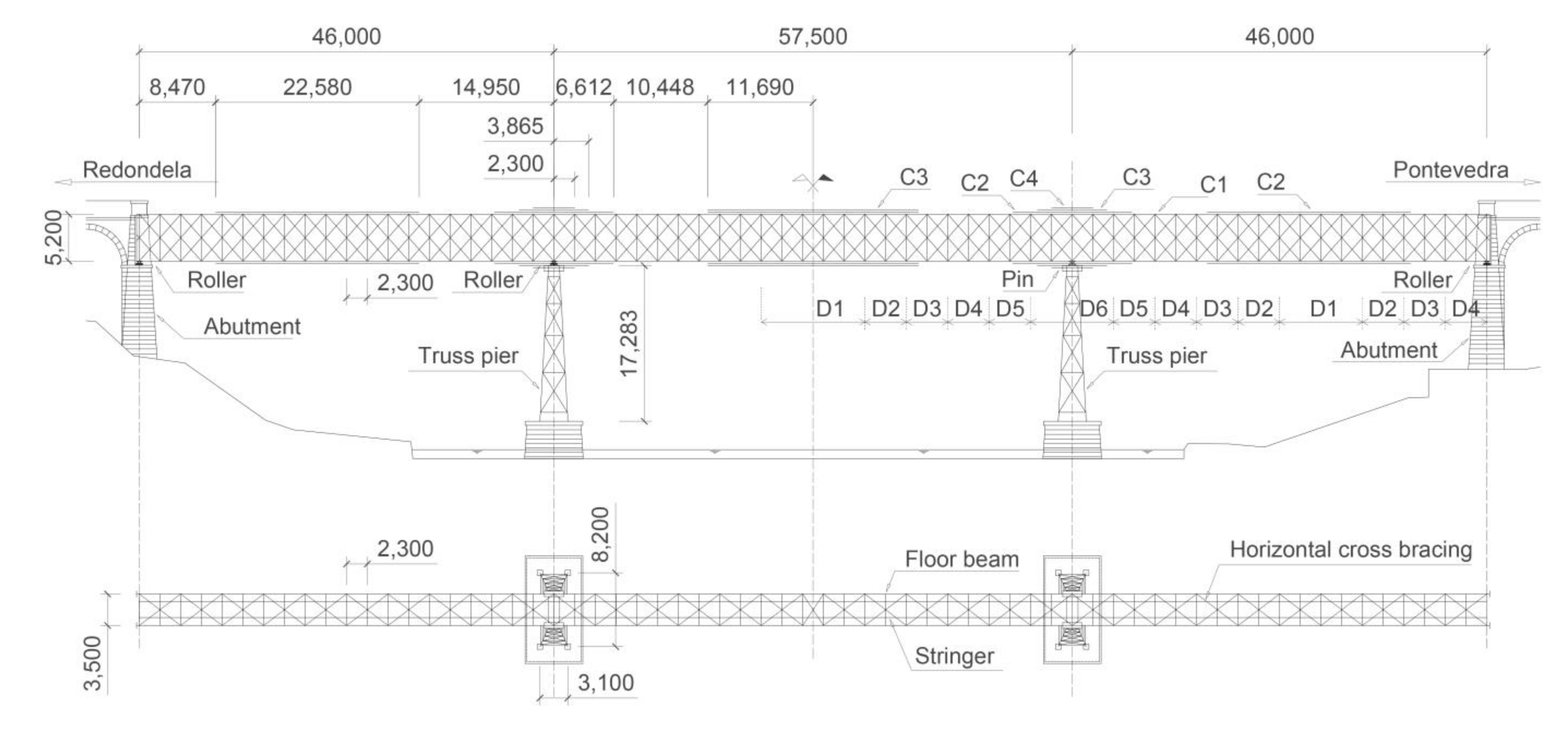
Figure 1. Redondela Bridge drawings: elevation and plan views (all dimensions in mm).
Metals 11 00603 g001
Figure 2. Redondela Bridge drawings: cross-sections (all dimensions in mm). (a) Bridge cross-section. (b) Element cross-sections.
Metals 11 00603 g002
Figure 3. General view of Redondela Bridge and 3D numerical model using SAP2000® software.
Metals 11 00603 g003
Figure 4. Train load models considered for the global FE analysis of the bridge (all dimensions in m). (a) UIC Load Model 71 according to [25]. (b) Load Model of the Spanish Standard for Railway Bridges in 1902 according to [29]. (c) Renfe 335 Series Locomotive + Renfe JJ92 wagons.
Metals 11 00603 g004aMetals 11 00603 g004b
Figure 5. First six mode shapes and their corresponding natural frequencies of the bridge. (a) Mode 1, f1 = 1.53 Hz. (b) Mode 2, f2 = 1.58 Hz. (c) Mode 3, f3 = 2.13 Hz. (d) Mode 4, f4 = 2.25 Hz. (e) Mode 5, f5 = 3.87 Hz. (f) Mode 6, f6 = 4.91 Hz.
Metals 11 00603 g005
Figure 6. Sketches of the tested connections with original stringers from Redondela bridge (all dimensions in mm). (a) Details of the connection. (b) Test set-up.
Metals 11 00603 g006aMetals 11 00603 g006b
Figure 7. Laboratory test of the non-strengthened connection.
Metals 11 00603 g007
Figure 8. Instrumentation of stringer-floor beam connection specimens (all dimensions in mm). (a) Strain rosette. (b) Displacement transducers.
Metals 11 00603 g008
Figure 9. Assembly of the stringer-floor beam connection Finite Element (FE) local model. (a) Exploded view of model parts. (b) Shell-to-solid coupling.
Metals 11 00603 g009
Figure 10. Boundary conditions of the connection model. (a) Anti-symmetry and symmetry boundary conditions. (b) Support, loading and pretension of rivets and bolts.
Metals 11 00603 g010
Figure 11. True stress-strain curves adopted for metallic materials in the local FE model.
Metals 11 00603 g011
Figure 12. Comparison between experimental and numerical results of the non-strengthened connection. (a) Moment-rotation. (b) Moment-strain.
Metals 11 00603 g012
Figure 13. Transversal logarithmic strain (LE22) in the connecting angle (local direction 2), for M = 19.50 kNm at the connection.
Metals 11 00603 g013
Figure 14. (a) Cut view of angle cross-section to define through-thickness path (points 1, 2, 3 and 4); (b) transversal logarithmic strain (LE22) through the thickness of the connecting angle at strain rosette location.
Metals 11 00603 g014
Figure 15. (a) Definition of longitudinal path along the height of connecting angle; (b) transversal logarithmic strain (LE22) along the height of connecting angle.
Metals 11 00603 g015
Figure 16. Maximum bending moment MC at stringer-floor beam connections corresponding with cross-section at intermediate bridge piers (global FE model). (a) Location of connections. (b) Bending moment at connections along the bridge.
Metals 11 00603 g016
Figure 17. Modified Goodman fatigue failure criterion in a constant fatigue-life diagram.
Metals 11 00603 g017
Figure 18. CFRP strengthening system for fatigue-prone detail (all dimensions in mm). (a) Lateral view. (b) Plan view.
Metals 11 00603 g018
Figure 19. Definition of the CFRP in the local FE model. (a) CFRP reference orientation. (b) Tie constraints.
Metals 11 00603 g019
Figure 20. Constant fatigue-life diagrams (CLD) for local FE model results. (a) UIC 71. (b) S335.
Metals 11 00603 g020
Figure 21. Principal stresses in ply 13 ( ply at the symmetry plane) of Laminate L3 for bending moment M = 19.50 kN at the connection.
Metals 11 00603 g021
Figure 22. Values of output variables related to damage initiation criteria, at the most critical ply in Laminate 3 for each damage initiation mechanism, for bending moment M = 19.50 kN at the connection. (a) HSNFTCRT, max = 0.01, (b) HSNFCCRT, max = 0.01, (c) HSNMTCRT, max = 0.05, (d) HSNMCCRT, max = 0.04.
Metals 11 00603 g022
Figure 23. Installation of CFRP angles on the connection. (a) Metal surface preparation. (b) CFRP adhesive bonding.
Metals 11 00603 g023
Figure 24. Test of the CFRP-strengthened connection.
Metals 11 00603 g024
Figure 25. Comparison between CFRP-strengthened and non-strengthened connection (experimental tests). (a) Moment-principal strain curves. (b) Constant fatigue-life diagram.
Metals 11 00603 g025
Table 1. Cross-section of main chords and diagonals.
Top/Bottom ChordsDiagonals
C12L90 × 90 × 13 + #450 × 13 + #500 × 13D12L75 × 75 × 7
C22L90 × 90 × 13 + #450 × 13 + 2#500 × 13D22L80 × 80 × 9
C32L90 × 90 × 13 + #450 × 13 + 2#500 × 13 + #500 × 14D32L80 × 80 × 10
C42L90 × 90 × 13 + #450 × 13 + 2#500 × 13 + #500 × 14 + #500 × 10D42L80 × 80 × 10 + #160 × 10
--D52L80 × 80 × 13 + #160 × 12
--D62L90 × 90 × 13 + #180 × 14
Table 2. Axle loads for each vehicle model analyzed.
Load ModelP (kN)Q (kN)q (kN/m)
UIC Load Model 71250-80
Spanish Standard 1902130105-
335 locomotive + JJ92 wagons205225-
Table 3. Mechanical properties of metallic materials used.
Mechanical PropertyPuddle IronRivetsS275 SteelGrade 6.8 Bolt
Tensile modulus (GPa)198198210210
Yield strength (MPa)313313275440
Tensile strength (MPa)367367430600
Table 4. Results from global and local numerical models (non-strengthened connection).
Train Load ModelKMCεmax, FEM(1)
kNm/radkNmμm
UIC Load Model 7110,65017.541439
Spanish Standard 190211,54010.64669
Renfe 335 Series + JJ92 wagons11,26415.191103
(1) FEM-R0.65 curve in Figure 11b.
Table 5. Orthotropic elastic properties of laminae.
FiberE1E2ν12G12G13G23
CF1117,146 (1)11,8530.322 (1)328532852968
CF2183,605 (1)10,9500.328 (1)303430342749
(1) Experimental values [6].
Table 6. Orthotropic strength properties of laminae.
FiberF1tF1cF2tF2cS1S2
CF11932 (1)48749.649.655.055.0
CF21663 (1)47650.550.555.355.3
(1) Experimental values [6].
Table 7. Plies arrangements for the stacking sequences evaluated in the local FE model.
Lam.Stacking SequenceThickness (mm)
L1[45°/–45°2/45°/0°/90°/0°]s5.20
L2[45°/–45°2/45°2/–45°/0°/90°2/0°]s7.48
L3[45°/–45°2/45°2/–45°2/45°/0°/90°2/0°/2]s10.40
Table 8. Mean stress and alternating stress amplitude obtained from the local FE models.
UIC 71Renfe S335Spanish Standard 1902
Local FE Modelσm (MPa)σa (MPa)σm (MPa)σa (MPa)σm (MPa)σa (MPa)
Non-strengthened150.48134.44117.22101.1874.2558.21
Laminate L1122.27106.2397.7281.68--
Laminate L2113.4697.4292.2776.23--
Laminate L3106.9290.8886.1370.09--
Table 9. Mean stress and alternating stress amplitude obtained from the experimental tests (corresponding to maximum bending moment MC for UIC 71 load model).
Test Specimenσm (MPa)σa (MPa)
Non-strengthened127.12111.08
CFRP-strengthened102.7686.72
Publisher’s Note: MDPI stays neutral with regard to jurisdictional claims in published maps and institutional affiliations.