A Review of Friction Stir Processing of Structural Metallic Materials: Process, Properties, and Methods


Abstract
1. Introduction
- (1)
- FSP is a solid-state, one-stage processing technique that provides grain refinement, strengthening, and structural homogeneity without changing the shape and size of the processed metallic material [33];
- (2)
- (3)
- the method is both environmentally friendly and energy efficient. FSP has greatly evolved over recent decades and have found many practical and scientific applications [33].
2. Friction Stir Processing
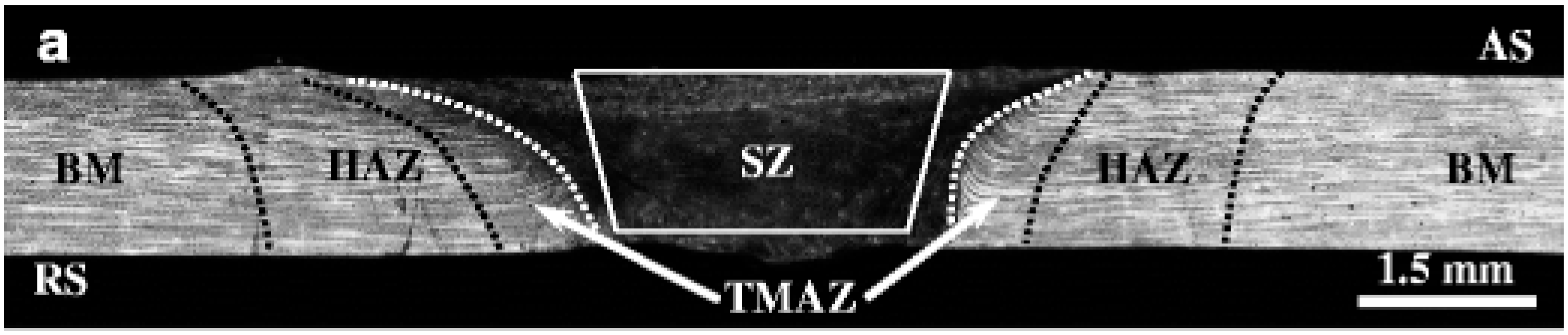
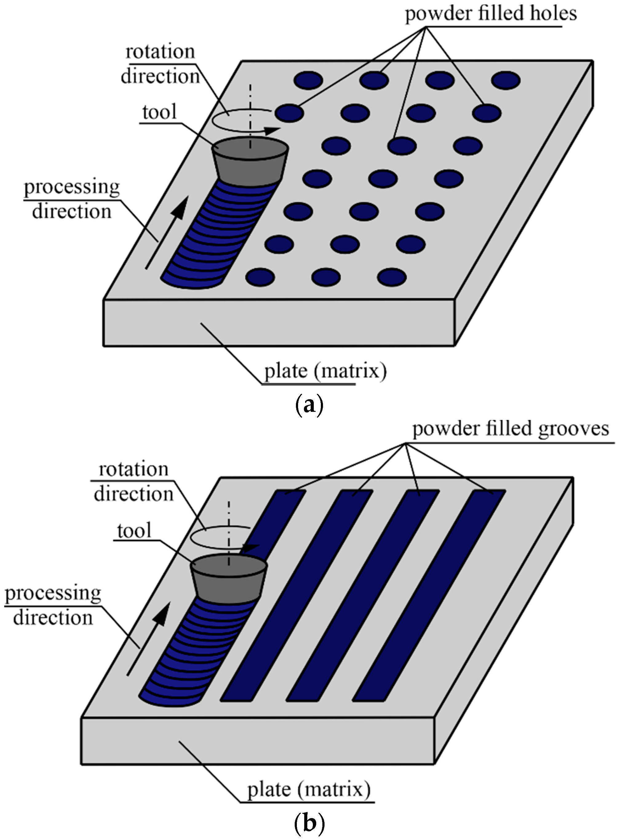
2.1. Principles and Processes
2.2. FSP Process Parameters
2.3. Microstructure in FSP
3. FSP Applications for Different Materials
3.1. FSP of Structural Alloys
3.2. FSP of Aluminum Alloys
3.3. FSP of Copper Alloys
3.4. FSP of Titanium Alloys
3.5. FSP of Magnesium Alloys
4. Friction Stir Processing of Particle-Reinforced Structural Alloys
5. Friction Stir Processing of Structural Alloys for Fabricating In Situ Hybrid Surfaces
6. Conclusions
- (1)
- with a subsurface gradient structure obtained through the formation of equiaxed nanograins and structural homogenization;
- (2)
- with a compositional subsurface gradient structure formed by modifying and hardening the material surface with reinforcing particles;
- (3)
- in situ composites.
Author Contributions
Funding
Conflicts of Interest
Nomenclature
| FSP | friction stir processing |
| FSW | friction stir welding |
| MH | microhardness |
| UTS | ultimate tensile strength |
| Elong | elongation |
| WT | wear testing |
| CR | corrosion resistance |
| IT | impact toughness |
| SWCNTs | single-walled carbon nanotubes |
| MWCNT | multi-walled carbon nanotubes |
| CNTs | carbon nanotubes |
| CS | compressive strength |
| HRTEM | high resolution transmission electron microscopy |
References
- Hekimoğlu, A.P.; Çalış, M.; Ayata, G. Effect of Strontium and Magnesium Additions on the Microstructure and Mechanical Properties of Al–12Si Alloys. Met. Mater. Int. 2019, 25, 1488–1499. [Google Scholar] [CrossRef]
- He, T.; Chen, W.; Wang, W.; Ren, F.; Stock, H.R. Effect of different Cu contents on the microstructure and hydrogen production of Al–Cu-Ga-In-Sn alloys for dissolvable materials. J. Alloys Compd. 2020, 821, 153489. [Google Scholar] [CrossRef]
- Trudonoshyn, O.; Rehm, S.; Randelzhofer, P. Körner Improvement of the high-pressure die casting alloy Al-5.7Mg-2.6Si-0.7Mn with Zn addition. Mater. Charact. 2019, 158, 109959. [Google Scholar] [CrossRef]
- Prach, O.; Trudonoshyn, O.; Randelzhofer, P.; Körner, C.; Durst, K. Effect of Zr, Cr and Sc on the Al–Mg–Si–Mn high-pressure die casting alloys. Mater. Sci. Eng. A 2019, 759, 603–612. [Google Scholar] [CrossRef]
- Fabrizi, A.; Ferraro, S.; Timelli, G. The influence of Sr, Mg and Cu addition on the microstructural properties of a secondary AlSi9Cu3(Fe) die casting alloy. Mater. Charact. 2013, 85, 13–25. [Google Scholar] [CrossRef]
- Seifeddine, S.; Johansson, S.; Svensson, I.L. The influence of cooling rate and manganese content on the β-Al5FeSi phase formation and mechanical properties of Al–Si-based alloys. Mater. Sci. Eng. A 2008, 490, 385–390. [Google Scholar] [CrossRef]
- Rao, Y.; Yan, H.; Hu, Z. Modification of eutectic silicon and β-Al5FeSi phases in as-cast ADC12 alloys by using samarium addition. J. Rare Earths 2013, 31, 916–922. [Google Scholar] [CrossRef]
- Cinkilic, E.; Ridgeway, C.D.; Yan, X.; Luo, A.A. A Formation Map of Iron-Containing Intermetallic Phases in Recycled Cast Aluminum Alloys. Metall. Mater. Trans. A Phys. Metall. Mater. Sci. 2019, 50, 5945–5956. [Google Scholar] [CrossRef]
- Irizalp, S.G.; Saklakoglu, N. Effect of Fe-rich intermetallics on the microstructure and mechanical properties of thixoformed A380 aluminum alloy. Eng. Sci. Technol. Int. J. 2014, 17, 58–62. [Google Scholar] [CrossRef]
- Mohamed, A.M.A.; Samuel, A.M.; Samuel, F.H.; Doty, H.W. Influence of additives on the microstructure and tensile properties of near-eutectic Al–10.8%Si cast alloy. Mater. Des. 2009, 30, 3943–3957. [Google Scholar] [CrossRef]
- Li, Q.; Xia, T.; Lan, Y.; Zhao, W.; Fan, L.; Li, P. Effect of in situ γ-Al2O3 particles on the microstructure of hypereutectic Al–20%Si alloy. J. Alloys Compd. 2013, 577, 232–236. [Google Scholar] [CrossRef]
- Huang, X.; Yan, H. Effect of trace la addition on the microstructure and mechanical property of as-cast ADC12 Al-Alloy. J. Wuhan Univ. Technol. Mater. Sci. Ed. 2013, 28, 202–205. [Google Scholar] [CrossRef]
- Li, J.H.; Wang, X.D.; Ludwig, T.H.; Tsunekawa, Y.; Arnberg, L.; Jiang, J.Z.; Schumacher, P. Modification of eutectic Si in Al–Si alloys with Eu addition. Acta Mater. 2015, 84, 153–163. [Google Scholar] [CrossRef]
- Czerwinski, F. Cerium in aluminum alloys. J. Mater. Sci. 2020, 55, 24–72. [Google Scholar] [CrossRef]
- Niu, G.; Mao, J.; Wang, J. Effect of Ce Addition on Fluidity of Casting Aluminum Alloy A356. Metall. Mater. Trans. A Phys. Metall. Mater. Sci. 2019, 50, 5935–5944. [Google Scholar] [CrossRef]
- Ravi, M.; Pillai, U.T.S.; Pai, B.C.; Damodaran, A.D.; Dwarakadasa, E.S. The effect of mischmetal addition on the structure and mechanical properties of a cast Al-7Si-0.3Mg alloy containing excess iron (up to 0.6 pct). Metall. Mater. Trans. A Phys. Metall. Mater. Sci. 2002, 33, 391–400. [Google Scholar] [CrossRef]
- Bijalwan, P.; Pandey, K.K.; Mukherjee, B.; Islam, A.; Pathak, A.; Dutta, M.; Keshri, A.K. Tailoring the bimodal zone in plasma sprayed CNT reinforced YSZ coating and its impact on mechanical and tribological properties. Surf. Coat. Technol. 2019, 377, 124870. [Google Scholar] [CrossRef]
- Gui, M.; Kang, S.B.; Euh, K. Influence of spraying conditions on microstructures of Al-SiCpcomposites by plasma spraying. Metall. Mater. Trans. A 2005, 36, 2471–2480. [Google Scholar] [CrossRef]
- Maharajan, S.; Ravindran, D.; Rajakarunakaran, S.; Khan, M.A. Analysis of surface properties of tungsten carbide (WC) coating over austenitic stainless steel (SS316) using plasma spray process. Mater. Today Proc. 2019. [Google Scholar] [CrossRef]
- Xi, H.; He, P.; Wang, H.; Liu, M.; Chen, S.; Xing, Z.; Ma, G.; Lv, Z. Microstructure and mechanical properties of Mo coating deposited by supersonic plasma spraying. Int. J. Refract. Met. Hard Mater. 2020, 86, 105095. [Google Scholar] [CrossRef]
- Padmini, B.V.; Mathapati, M.; Niranjan, H.B.; Sampathkumaran, P.; Seetharamu, S.; Ramesh, M.R.; Mohan, N. High temperature tribological studies of cold sprayed nickel based alloy on low carbon steels. Mater. Today Proc. 2019. [Google Scholar] [CrossRef]
- Liu, Z.; Wang, H.; Haché, M.; Irissou, E.; Zou, Y. Formation of refined grains below 10 nm in size and nanoscale interlocking in the particle–particle interfacial regions of cold sprayed pure aluminum. Scr. Mater. 2020, 177, 96–100. [Google Scholar] [CrossRef]
- Dabney, T.; Johnson, G.; Yeom, H.; Maier, B.; Walters, J.; Sridharan, K. Experimental evaluation of cold spray FeCrAl alloys coated zirconium-alloy for potential accident tolerant fuel cladding. Nucl. Mater. Energy 2019, 21, 100715. [Google Scholar] [CrossRef]
- Hu, C.; Baker, T.N. A new aluminium silicon carbide formed in laser processing. J. Mater. Sci. 1997, 32, 5047–5051. [Google Scholar] [CrossRef]
- Pantelis, D.; Tissandier, A.; Manolatos, P.; Ponthiaux, P. Formation of wear resistant Al–SiC surface composite by laser melt–particle injection process. Mater. Sci. Technol. 1995, 11, 299–303. [Google Scholar] [CrossRef]
- Katipelli, L.R.; Dahotre, N.B. Mechanism of high temperature oxidation of laser surface engineered TiC/Al alloy ‘composite’ coating on 6061 aluminium alloy. Mater. Sci. Technol. 2001, 17, 1061–1068. [Google Scholar] [CrossRef]
- Dong, M.; Cui, X.; Lu, B.; Jin, G.; Cai, Z.; Feng, X.; Liu, Z.; Wang, H. Effect of Ti+N and Zr+N ions implantation on mechanical and corrosion performance of carburized layer. Thin Solid Films 2019, 692, 137597. [Google Scholar] [CrossRef]
- Chen, T.; Castanon, E.; Gigax, J.G.; Kim, H.; Balerio, R.; Fan, J.; Garner, F.A.; Shao, L. Nitrogen ion implantation into pure iron for formation of surface nitride layer. Nucl. Instruments Methods Phys. Res. Sect. B Beam Interact. Mater. Atoms 2019, 451, 10–13. [Google Scholar] [CrossRef]
- Acciari, H.A.; Palma, D.P.S.; Codaro, E.N.; Zhou, Q.; Wang, J.; Ling, Y.; Zhang, J.; Zhang, Z. Surface modifications by both anodic oxidation and ion beam implantation on electropolished titanium substrates. Appl. Surf. Sci. 2019, 487, 1111–1120. [Google Scholar] [CrossRef]
- Titov, A.I.; Karaseov, P.A.; Karabeshkin, K.V.; Ermolaeva, G.M.; Shilov, V.B. Effect of monatomic and molecular ion irradiation on time resolved photoluminescence decay in GaN. Nucl. Instruments Methods Phys. Res. Sect. B Beam Interact. Mater. Atoms 2019, 458, 164–168. [Google Scholar] [CrossRef]
- Stepanov, A.L.; Vorobev, V.V.; Rogov, A.M.; Nuzhdin, V.I.; Valeev, V.F. Sputtering of silicon surface by silver-ion implantation. Nucl. Instruments Methods Phys. Res. Sect. B Beam Interact. Mater. Atoms 2019, 457, 1–3. [Google Scholar] [CrossRef]
- Kalashnikov, M.P.; Fedorischeva, M.V.; Sergeev, V.P.; Neyfeld, V.V.; Popova, N.A. Features of surface layer structure of VT23 titanium alloy under bombardment with copper ions. AIP Conf. Proc. 2015, 1683. [Google Scholar] [CrossRef]
- Ma, Z.Y. Friction Stir Processing Technology: A Review. Metall. Mater. Trans. A 2008, 39, 642–658. [Google Scholar] [CrossRef]
- Kumar, R.A.; Kumar, R.G.A.; Ahamed, K.A.; Alstyn, B.D.; Vignesh, V. Review of Friction Stir Processing of Aluminium Alloys. Mater. Today Proc. 2019, 16, 1048–1054. [Google Scholar] [CrossRef]
- Węglowski, M.S. Friction stir processing – State of the art. Arch. Civ. Mech. Eng. 2018, 18, 114–129. [Google Scholar] [CrossRef]
- Padhy, G.K.; Wu, C.S.; Gao, S. Friction stir based welding and processing technologies - processes, parameters, microstructures and applications: A review. J. Mater. Sci. Technol. 2018, 34, 1–38. [Google Scholar] [CrossRef]
- Rao, A.G.; Ravi, K.R.; Ramakrishnarao, B.; Deshmukh, V.P.; Sharma, A.; Prabhu, N.; Kashyap, B.P. Recrystallization Phenomena During Friction Stir Processing of Hypereutectic Aluminum-Silicon Alloy. Metall. Mater. Trans. A 2013, 44, 1519–1529. [Google Scholar] [CrossRef]
- Sun, H.; Yang, S.; Jin, D. Improvement of Microstructure, Mechanical Properties and Corrosion Resistance of Cast Al--12Si Alloy by Friction Stir Processing. Trans. Indian Inst. Met. 2018, 71, 985–991. [Google Scholar] [CrossRef]
- Zhao, H.; Pan, Q.; Qin, Q.; Wu, Y.; Su, X. Effect of the processing parameters of friction stir processing on the microstructure and mechanical properties of 6063 aluminum alloy. Mater. Sci. Eng. A 2019, 751, 70–79. [Google Scholar] [CrossRef]
- Abrahams, R.; Mikhail, J.; Fasihi, P. Effect of friction stir process parameters on the mechanical properties of 5005-H34 and 7075-T651 aluminium alloys. Mater. Sci. Eng. A 2019, 751, 363–373. [Google Scholar] [CrossRef]
- Kalashnikov, K.N.; Vorontsov, A.V.; Kalashnikova, T.A.; Chumaevskii, A.V. Changes in the structure and properties of aluminum alloys during friction stir processing by different types of tools. AIP Conf. Proc. 2018, 2053, 40038. [Google Scholar] [CrossRef]
- Kalashnikov, K.N.; Tarasov, S.Y.; Chumaevskii, A.V.; Fortuna, S.V.; Eliseev, A.A.; Ivanov, A.N. Towards aging in a multipass friction stir--processed AA2024. Int. J. Adv. Manuf. Technol. 2019, 103, 2121–2132. [Google Scholar] [CrossRef]
- Ramesh, K.N.; Pradeep, S.; Pancholi, V. Multipass Friction-Stir Processing and its Effect on Mechanical Properties of Aluminum Alloy 5086. Metall. Mater. Trans. A 2012, 43, 4311–4319. [Google Scholar] [CrossRef]
- Senthilkumar, R.; Prakash, M.; Arun, N.; Jeyakumar, A.A. The effect of the number of passes in friction stir processing of aluminum alloy (AA6082) and its failure analysis. Appl. Surf. Sci. 2019, 491, 420–431. [Google Scholar] [CrossRef]
- Barmouz, M.; Givi, M.K.B.; Seyfi, J. On the role of processing parameters in producing Cu/SiC metal matrix composites via friction stir processing: Investigating microstructure, microhardness, wear and tensile behavior. Mater. Charact. 2011, 62, 108–117. [Google Scholar] [CrossRef]
- Cartigueyen, S.; Mahadevan, K. Role of Friction Stir Processing on Copper and Copper based Particle Reinforced Composites—A Review. J. Mater. Sci. Surf. Eng. 2015, 2, 133–145. [Google Scholar]
- Surekha, K.; Els-Botes, A. Development of high strength, high conductivity copper by friction stir processing. Mater. Des. 2011, 32, 911–916. [Google Scholar] [CrossRef]
- Wang, Y.; Fu, R.; Jing, L.; Li, Y.; Sang, D. Grain refinement and nanostructure formation in pure copper during cryogenic friction stir processing. Mater. Sci. Eng. A 2017, 703, 470–476. [Google Scholar] [CrossRef]
- Cartigueyen, S.; Mahadevan, K. Influence of rotational speed on the formation of friction stir processed zone in pure copper at low-heat input conditions. J. Manuf. Process. 2015, 18, 124–130. [Google Scholar] [CrossRef]
- Bheekya Naik, R.; Venkateswara Reddy, K.; Madhusudhan Reddy, G.; Arockia Kumar, R. Development of High-Strength and High-Electrical Conductivity Cu--Zr Alloy Through Friction Stir Processing. Trans. Indian Inst. Met. 2019, 72, 1431–1435. [Google Scholar] [CrossRef]
- Jiang, L.; Huang, W.; Liu, C.; Chai, L.; Yang, X.; Xu, Q. Microstructure, texture evolution and mechanical properties of pure Ti by friction stir processing with slow rotation speed. Mater. Charact. 2019, 148, 1–8. [Google Scholar] [CrossRef]
- Mironov, S.; Sato, Y.S.; Kokawa, H. Development of grain structure during friction stir welding of pure titanium. Acta Mater. 2009, 57, 4519–4528. [Google Scholar] [CrossRef]
- Liu, F.C.; Liao, J.; Gao, Y.; Nakata, K. Influence of texture on strain localization in stir zone of friction stir welded titanium. J. Alloys Compd. 2015, 626, 304–308. [Google Scholar] [CrossRef]
- Zhang, W.; Ding, H.; Cai, M.; Yang, W.; Li, J. Ultra-grain refinement and enhanced low-temperature superplasticity in a friction stir-processed Ti-6Al-4V alloy. Mater. Sci. Eng. A 2018, 727, 90–96. [Google Scholar] [CrossRef]
- Vakili-Azghandi, M.; Roknian, M.; Szpunar, J.A.; Mousavizade, S.M. Surface modification of pure titanium via friction stir processing: Microstructure evolution and dry sliding wear performance. J. Alloys Compd. 2020, 816, 152557. [Google Scholar] [CrossRef]
- Kalashnikov, K.N.; Kalashnikova, T.A.; Chumaevskii, A.V.; Tarasov, S.Y.; Rubtsov, V.E.; Ivanov, A.N.; Kolubaev, E.A. High-strength friction stir processed dispersion hardened Al-Cu-Mg alloy. AIP Conf. Proc. 2017, 1909, 1–5. [Google Scholar] [CrossRef]
- Kalashnikov, K.N.; Kalashnikova, T.A.; Chumaevskii, A.V.; Ivanov, A.N.; Tarasov, S.Y.; Rubtsov, V.E.; Kolubaev, E.A. Friction-stir processed ultrafine grain high-strength Al-Mg alloy material. AIP Conf. Proc. 2017, 1909, 1–6. [Google Scholar] [CrossRef]
- Barati, M.; Abbasi, M.; Abedini, M. The effects of friction stir processing and friction stir vibration processing on mechanical, wear and corrosion characteristics of Al6061/SiO2 surface composite. J. Manuf. Process. 2019, 45, 491–497. [Google Scholar] [CrossRef]
- Dolatkhah, A.; Golbabaei, P.; Givi, M.K.B.; Molaiekiya, F. Investigating effects of process parameters on microstructural and mechanical properties of Al5052/SiC metal matrix composite fabricated via friction stir processing. Mater. Des. 2012, 37, 458–464. [Google Scholar] [CrossRef]
- Huang, C.W.; Aoh, J.N. Friction stir processing of copper-coated SiC particulate-reinforced aluminum matrix composite. Materials 2018, 11, 599. [Google Scholar] [CrossRef]
- Manochehrian, A.; Heidarpour, A.; Mazaheri, Y.; Ghasemi, S. On the surface reinforcing of A356 aluminum alloy by nanolayered Ti3AlC2 MAX phase via friction stir processing. Surf. Coat. Technol. 2019, 377, 124884. [Google Scholar] [CrossRef]
- Jain, V.K.S.; Varghese, J.; Muthukumaran, S. Effect of First and Second Passes on Microstructure and Wear Properties of Titanium Dioxide-Reinforced Aluminum Surface Composite via Friction Stir Processing. Arab. J. Sci. Eng. 2019, 44, 949–957. [Google Scholar] [CrossRef]
- Abraham, S.J.; Dinaharan, I.; Selvam, J.D.R.; Akinlabi, E.T. Microstructural characterization of vanadium particles reinforced AA6063 aluminum matrix composites via friction stir processing with improved tensile strength and appreciable ductility. Compos. Commun. 2019, 12, 54–58. [Google Scholar] [CrossRef]
- Bourkhani, R.D.; Eivani, A.R.; Nateghi, H.R. Through-thickness inhomogeneity in microstructure and tensile properties and tribological performance of friction stir processed AA1050-Al2O3 nanocomposite. Compos. Part B Eng. 2019, 174, 107061. [Google Scholar] [CrossRef]
- Zahmatkesh, B.; Enayati, M.H. A novel approach for development of surface nanocomposite by friction stir processing. Mater. Sci. Eng. A 2010, 527, 6734–6740. [Google Scholar] [CrossRef]
- Prabhu, M.S.; Perumal, A.E.; Arulvel, S.; Issac, R.F. Friction and wear measurements of friction stir processed aluminium alloy 6082/CaCO3 composite. Measurement 2019, 142, 10–20. [Google Scholar] [CrossRef]
- Deore, H.A.; Mishra, J.; Rao, A.G.; Mehtani, H.; Hiwarkar, V.D. Effect of filler material and post process ageing treatment on microstructure, mechanical properties and wear behaviour of friction stir processed AA 7075 surface composites. Surf. Coat. Technol. 2019, 374, 52–64. [Google Scholar] [CrossRef]
- Zhang, S.; Chen, G.; Wei, J.; Liu, Y.; Xie, R.; Liu, Q.; Zeng, S.; Zhang, G.; Shi, Q. Effects of energy input during friction stir processing on microstructures and mechanical properties of aluminum/carbon nanotubes nanocomposites. J. Alloys Compd. 2019, 798, 523–530. [Google Scholar] [CrossRef]
- Nazari, M.; Eskandari, H.; Khodabakhshi, F. Production and characterization of an advanced AA6061-Graphene-TiB2 hybrid surface nanocomposite by multi-pass friction stir processing. Surf. Coat. Technol. 2019, 377, 124914. [Google Scholar] [CrossRef]
- Pol, N.; Verma, G.; Pandey, R.P.; Shanmugasundaram, T. Fabrication of AA7005/TiB2-B4C surface composite by friction stir processing: Evaluation of ballistic behaviour. Def. Technol. 2019, 15, 363–368. [Google Scholar] [CrossRef]
- Dinaharan, I.; Sathiskumar, R.; Murugan, N. Effect of ceramic particulate type on microstructure and properties of copper matrix composites synthesized by friction stir processing. J. Mater. Res. Technol. 2016, 5, 302–316. [Google Scholar] [CrossRef]
- Heidarpour, A.; Mazaheri, Y.; Roknian, M.; Ghasemi, S. Development of Cu-TiO2 surface nanocomposite by friction stir processing: Effect of pass number on microstructure, mechanical properties, tribological and corrosion behavior. J. Alloys Compd. 2019, 783, 886–897. [Google Scholar] [CrossRef]
- Thankachan, T.; Prakash, K.S.; Kavimani, V. Investigating the effects of hybrid reinforcement particles on the microstructural, mechanical and tribological properties of friction stir processed copper surface composites. Compos. Part B Eng. 2019, 174, 107057. [Google Scholar] [CrossRef]
- Sharma, S.; Handa, A.; Singh, S.S.; Verma, D. Influence of tool rotation speeds on mechanical and morphological properties of friction stir processed nano hybrid composite of MWCNT-Graphene-AZ31 magnesium. J. Magnes. Alloy. 2019, 7, 487–500. [Google Scholar] [CrossRef]
- Arokiasamy, S.; Ronald, B.A. Enhanced properties of Magnesium based metal matrix composites via Friction Stir Processing. Mater. Today Proc. 2018, 5, 6934–6939. [Google Scholar] [CrossRef]
- Satish Kumar, T.; Suganya Priyadharshini, G.; Shalini, S.; Krishna Kumar, K.; Subramanian, R. Characterization of NbC-Reinforced AA7075 Alloy Composites Produced Using Friction Stir Processing. Trans. Indian Inst. Met. 2019, 72, 1593–1596. [Google Scholar] [CrossRef]
- Gangil, N.; Nagar, H.; Kumar, R.; Singh, D. Shape memory alloy reinforced magnesium matrix composite fabricated via friction stir processing. Mater. Today Proc. 2020. [Google Scholar] [CrossRef]
- Adetunla, A.; Akinlabi, E. Fabrication of Aluminum Matrix Composites for Automotive Industry Via Multipass Friction Stir Processing Technique. Int. J. Automot. Technol. 2019, 20, 1079–1088. [Google Scholar] [CrossRef]
- Fotoohi, H.; Lotfi, B.; Sadeghian, Z.; Byeon, J. Microstructural characterization and properties of in situ Al-Al3Ni/TiC hybrid composite fabricated by friction stir processing using reactive powder. Mater. Charact. 2019, 149, 124–132. [Google Scholar] [CrossRef]
- Alidokht, S.A.; Abdollah-zadeh, A.; Soleymani, S.; Assadi, H. Microstructure and tribological performance of an aluminium alloy based hybrid composite produced by friction stir processing. Mater. Des. 2011, 32, 2727–2733. [Google Scholar] [CrossRef]
- Dinaharan, I.; Akinlabi, E.T. Low cost metal matrix composites based on aluminum, magnesium and copper reinforced with fly ash prepared using friction stir processing. Compos. Commun. 2018, 9, 22–26. [Google Scholar] [CrossRef]
- Azimi-Roeen, G.; Kashani-Bozorg, S.F.; Nosko, M.; Nagy, Š.; Matko, I. Correction to: Formation of Al/(Al13Fe4 + Al2O3) Nano-composites via Mechanical Alloying and Friction Stir Processing. J. Mater. Eng. Perform. 2018, 27, 6800. [Google Scholar] [CrossRef]
- Mahmoud, E.R.I.; Al-qozaim, A.M.A. Fabrication of In-Situ Al--Cu Intermetallics on Aluminum Surface by Friction Stir Processing. Arab. J. Sci. Eng. 2016, 41, 1757–1769. [Google Scholar] [CrossRef]
- Golmohammadi, M.; Atapour, M.; Ashrafi, A. Fabrication and wear characterization of an A413/Ni surface metal matrix composite fabricated via friction stir processing. Mater. Des. 2015, 85, 471–482. [Google Scholar] [CrossRef]
- Qian, J.; Li, J.; Xiong, J.; Zhang, F.; Lin, X. In situ synthesizing Al3Ni for fabrication of intermetallic-reinforced aluminum alloy composites by friction stir processing. Mater. Sci. Eng. A 2012, 550, 279–285. [Google Scholar] [CrossRef]
- Zeidabadi, S.R.H.; Daneshmanesh, H. Fabrication and characterization of in-situ Al/Nb metal/intermetallic surface composite by friction stir processing. Mater. Sci. Eng. A 2017, 702, 189–195. [Google Scholar] [CrossRef]
- Khodabakhshi, F.; Arab, S.M.; Švec, P.; Gerlich, A.P. Fabrication of a new Al-Mg/graphene nanocomposite by multi-pass friction-stir processing: Dispersion, microstructure, stability, and strengthening. Mater. Charact. 2017, 132, 92–107. [Google Scholar] [CrossRef]
- Wang, T.; Gwalani, B.; Shukla, S.; Frank, M.; Mishra, R.S. Development of in situ composites via reactive friction stir processing of Ti–B4C system. Compos. Part B Eng. 2019, 172, 54–60. [Google Scholar] [CrossRef]
- Khodabakhshi, F.; Rahmati, R.; Nosko, M.; Orovčík, L.; Nagy, Š.; Gerlich, A.P. Orientation structural mapping and textural characterization of a CP-Ti/HA surface nanocomposite produced by friction-stir processing. Surf. Coat. Technol. 2019, 374, 460–475. [Google Scholar] [CrossRef]
- Kumar, H.; Prasad, R.; Kumar, P.; Tewari, S.P.; Singh, J.K. Mechanical and tribological characterization of industrial wastes reinforced aluminum alloy composites fabricated via friction stir processing. J. Alloys Compd. 2020, 831, 154832. [Google Scholar] [CrossRef]
- Kumar, K.N.; Aravindkumar, N.; Eswaramoorthi, K. Fabrication of AA6016/(Al2O3 + AlN) hybrid surface composite using friction stir processing. Mater. Today Proc. 2020. [Google Scholar] [CrossRef]
- Mishra, R.S.; Ma, Z.Y. Friction stir welding and processing. Mater. Sci. Eng. R Reports 2005, 50, 1–78. [Google Scholar] [CrossRef]
- Li, K.; Liu, X.; Zhao, Y. Research Status and Prospect of Friction Stir Processing Technology. Coatings 2019, 9, 129. [Google Scholar] [CrossRef]
- Tarasov, S.Y.; Rubtsov, V.E.; Fortuna, S.V.; Eliseev, A.A.; Chumaevsky, A.V.; Kalashnikova, T.A.; Kolubaev, E.A. Ultrasonic-assisted aging in friction stir welding on Al-Cu-Li-Mg aluminum alloy. Weld. World 2017, 61, 679–690. [Google Scholar] [CrossRef]
- Sathiskumar, R.; Murugan, N.; Dinaharan, I.; Vijay, S.J. Role of friction stir processing parameters on microstructure and microhardness of boron carbide particulate reinforced copper surface composites. Sadhana 2013, 38, 1433–1450. [Google Scholar] [CrossRef]
- Chen, C.F.; Kao, P.W.; Chang, L.W.; Ho, N.J. Effect of processing parameters on microstructure and mechanical properties of an Al-Al11Ce3-Al2O3 in-situ composite produced by friction stir processing. Metall. Mater. Trans. A Phys. Metall. Mater. Sci. 2010, 41, 513–522. [Google Scholar] [CrossRef]
- Shahi, A.; Sohi, M.H.; Ahmadkhaniha, D.; Ghambari, M. In situ formation of Al–Al3Ni composites on commercially pure aluminium by friction stir processing. Int. J. Adv. Manuf. Technol. 2014, 75, 1331–1337. [Google Scholar] [CrossRef]
- You, G.L.; Ho, N.J.; Kao, P.W. Aluminum based in situ nanocomposite produced from Al–Mg–CuO powder mixture by using friction stir processing. Mater. Lett. 2013, 100, 219–222. [Google Scholar] [CrossRef]
- Hsu, C.J.; Kao, P.W.; Ho, N.J. Ultrafine-grained Al–Al2Cu composite produced in situ by friction stir processing. Scr. Mater. 2005, 53, 341–345. [Google Scholar] [CrossRef]
- Fattah-alhosseini, A.; Vakili-Azghandi, M.; Sheikhi, M.; Keshavarz, M.K. Passive and electrochemical response of friction stir processed pure Titanium. J. Alloys Compd. 2017, 704, 499–508. [Google Scholar] [CrossRef]
- Al-Fadhalah, K.J.; Almazrouee, A.I.; Aloraier, A.S. Microstructure and mechanical properties of multi-pass friction stir processed aluminum alloy 6063. Mater. Des. 2014, 53, 550–560. [Google Scholar] [CrossRef]
- Nakata, K.; Kim, Y.G.; Fujii, H.; Tsumura, T.; Komazaki, T. Improvement of mechanical properties of aluminum die casting alloy by multi-pass friction stir processing. Mater. Sci. Eng. A 2006, 437, 274–280. [Google Scholar] [CrossRef]
- El-Rayes, M.M.; El-Danaf, E.A. The influence of multi-pass friction stir processing on the microstructural and mechanical properties of Aluminum Alloy 6082. J. Mater. Process. Technol. 2012, 212, 1157–1168. [Google Scholar] [CrossRef]
- Girish, G.; Anandakrishnan, V. Determination of friction stir processing window for AA7075. Mater. Today Proc. 2020, 21, 557–562. [Google Scholar] [CrossRef]
- Yang, R.; Zhang, Z.; Zhao, Y.; Chen, G.; Guo, Y.; Liu, M.; Zhang, J. Effect of multi-pass friction stir processing on microstructure and mechanical properties of Al3Ti/A356 composites. Mater. Charact. 2015, 106, 62–69. [Google Scholar] [CrossRef]
- John, J.; Shanmughanatan, S.P.; Kiran, M.B. Effect of tool geometry on microstructure and mechanical Properties of friction stir processed AA2024-T351 aluminium alloy. Mater. Today Proc. 2018, 5, 2965–2979. [Google Scholar] [CrossRef]
- Cartigueyen, S.; Mahadevan, K. Study of friction stir processed zone under different tool pin profiles in pure copper. IOSR J. Mech. Civ. Eng. 2014, 11, 6–12. [Google Scholar] [CrossRef]
- Vijayavel, P.; Balasubramanian, V. Effect of pin profile volume ratio on microstructure and tensile properties of friction stir processed aluminum based metal matrix composites. J. Alloys Compd. 2017, 729, 828–842. [Google Scholar] [CrossRef]
- Surekha, K.; Murty, B.S.; Rao, K.P. Microstructural characterization and corrosion behavior of multipass friction stir processed AA2219 aluminium alloy. Surf. Coat. Technol. 2008, 202, 4057–4068. [Google Scholar] [CrossRef]
- Barmouz, M.; Besharati Givi, M.K.; Jafari, J. Evaluation of Tensile Deformation Properties of Friction Stir Processed Pure Copper: Effect of Processing Parameters and Pass Number. J. Mater. Eng. Perform. 2014, 23, 101–107. [Google Scholar] [CrossRef]
- Luo, P.; McDonald, D.T.; Xu, W.; Palanisamy, S.; Dargusch, M.S.; Xia, K. A modified Hall–Petch relationship in ultrafine-grained titanium recycled from chips by equal channel angular pressing. Scr. Mater. 2012, 66, 785–788. [Google Scholar] [CrossRef]
- Besharati Givi, M.K.; Asadi, P.; Bag, S.; Yaduwanshi, D.; Pal, S.; Heidarzadeh, A.; Mudani, S.; Kazemi-Choobi, K.; Hanifian, H.; Braga, D.; et al. Advances in Friction-Stir Welding and Processing; Elsevier: Amsterdam, The Netherlands, 2014; ISBN 9780857094544. [Google Scholar]
- Babu, J.; Anjaiah, M.; Mathew, A. Experimental studies on Friction stir processing of AZ31 Magnesium alloy. Mater. Today Proc. 2018, 5, 4515–4522. [Google Scholar] [CrossRef]
- Pan, L.; Kwok, C.T.; Lo, K.H. Friction-stir processing of AISI 440C high-carbon martensitic stainless steel for improving hardness and corrosion resistance. J. Mater. Process. Technol. 2020, 277, 116448. [Google Scholar] [CrossRef]
- Lashgari, H.R.; Kong, C.; Asnavandi, M.; Zangeneh, S. The effect of friction stir processing (FSP) on the microstructure, nanomechanical and corrosion properties of low carbon CoCr28Mo5 alloy. Surf. Coat. Technol. 2018, 354, 390–404. [Google Scholar] [CrossRef]
- Jiang, X.; Overman, N.; Canfield, N.; Ross, K. Friction stir processing of dual certified 304/304L austenitic stainless steel for improved cavitation erosion resistance. Appl. Surf. Sci. 2019, 471, 387–393. [Google Scholar] [CrossRef]
- Grewal, H.S.; Arora, H.S.; Singh, H.; Agrawal, A. Surface modification of hydroturbine steel using friction stir processing. Appl. Surf. Sci. 2013, 268, 547–555. [Google Scholar] [CrossRef]
- Yasavol, N.; Jafari, H. Microstructure, Mechanical and Corrosion Properties of Friction Stir-Processed AISI D2 Tool Steel. J. Mater. Eng. Perform. 2015, 24, 2151–2157. [Google Scholar] [CrossRef]
- Singh, S.; Kaur, M.; Saravanan, I. Enhanced microstructure and mechanical properties of boiler steel via Friction Stir Processing. Mater. Today Proc. 2020, 22, 482–486. [Google Scholar] [CrossRef]
- Wang, T.; Shukla, S.; Komarasamy, M.; Liu, K.; Mishra, R.S. Towards heterogeneous AlxCoCrFeNi high entropy alloy via friction stir processing. Mater. Lett. 2019, 236, 472–475. [Google Scholar] [CrossRef]
- Yang, X.; Yan, Z.; Dong, P.; Cheng, B.; Zhang, J.; Zhang, T.; Zhang, H.; Wang, W. Surface modification of aluminum alloy by incorporation of AlCoCrFeNi high entropy alloy particles via underwater friction stir processing. Surf. Coat. Technol. 2020, 385, 125438. [Google Scholar] [CrossRef]
- Wang, T.; Komarasamy, M.; Shukla, S.; Mishra, R.S. Simultaneous enhancement of strength and ductility in an AlCoCrFeNi2.1 eutectic high-entropy alloy via friction stir processing. J. Alloys Compd. 2018, 766, 312–317. [Google Scholar] [CrossRef]
- Yang, X.; Dong, P.; Yan, Z.; Cheng, B.; Zhai, X.; Chen, H.; Zhang, H.; Wang, W. AlCoCrFeNi high-entropy alloy particle reinforced 5083Al matrix composites with fine grain structure fabricated by submerged friction stir processing. J. Alloys Compd. 2020, 836, 155411. [Google Scholar] [CrossRef]
- Sinha, S.; Nene, S.S.; Frank, M.; Liu, K.; Lebensohn, R.A.; Mishra, R.S. Deformation mechanisms and ductile fracture characteristics of a friction stir processed transformative high entropy alloy. Acta Mater. 2020, 184, 164–178. [Google Scholar] [CrossRef]
- Shukla, S.; Wang, T.; Frank, M.; Agrawal, P.; Sinha, S.; Mirshams, R.A.; Mishra, R.S. Friction stir gradient alloying: A novel solid-state high throughput screening technique for high entropy alloys. Mater. Today Commun. 2020, 23, 100869. [Google Scholar] [CrossRef]
- Leal, R.M.; Galvão, I.; Loureiro, A.; Rodrigues, D.M. Effect of friction stir processing parameters on the microstructural and electrical properties of copper. Int. J. Adv. Manuf. Technol. 2015, 80, 1655–1663. [Google Scholar] [CrossRef]
- Peng, J.; Zhang, Z.; Huang, J.; Guo, P.; Li, Y.; Zhou, W.; Wu, Y. The effect of the inhomogeneous microstructure and texture on the mechanical properties of AZ31 Mg alloys processed by friction stir processing. J. Alloys Compd. 2019, 792, 16–24. [Google Scholar] [CrossRef]
- Wang, Y.; Huang, Y.; Meng, X.; Wan, L.; Feng, J. Microstructural evolution and mechanical properties of MgZnYZr alloy during friction stir processing. J. Alloys Compd. 2017, 696, 875–883. [Google Scholar] [CrossRef]
- Shang, Q.; Ni, D.R.; Xue, P.; Xiao, B.L.; Wang, K.S.; Ma, Z.Y. An approach to enhancement of Mg alloy joint performance by additional pass of friction stir processing. J. Mater. Process. Technol. 2019, 264, 336–345. [Google Scholar] [CrossRef]
- Du, X.; Wu, B. Using two-pass friction stir processing to produce nanocrystalline microstructure in AZ61 magnesium alloy. Sci. China Ser. E Technol. Sci. 2009, 52, 1751–1755. [Google Scholar] [CrossRef]
- Huang, L.; Wang, K.; Wang, W.; Yuan, J.; Qiao, K.; Yang, T.; Peng, P.; Li, T. Effects of grain size and texture on stress corrosion cracking of friction stir processed AZ80 magnesium alloy. Eng. Fail. Anal. 2018, 92, 392–404. [Google Scholar] [CrossRef]
- Jin, Y.; Wang, K.; Wang, W.; Peng, P.; Zhou, S.; Huang, L.; Yang, T.; Qiao, K.; Zhang, B.; Cai, J.; et al. Microstructure and mechanical properties of AE42 rare earth-containing magnesium alloy prepared by friction stir processing. Mater. Charact. 2019, 150, 52–61. [Google Scholar] [CrossRef]
- MD, F.K.; Karthik, G.M.; Panigrahi, S.K.; Ram, G.D.J. Friction stir processing of QE22 magnesium alloy to achieve ultrafine-grained microstructure with enhanced room temperature ductility and texture weakening. Mater. Charact. 2019, 147, 365–378. [Google Scholar] [CrossRef]
- Johannes, L.B.; Yowell, L.L.; Sosa, E.; Arepalli, S.; Mishra, R.S. Survivability of single-walled carbon nanotubes during friction stir processing. Nanotechnology 2006, 17, 3081–3084. [Google Scholar] [CrossRef]
- Reddy, K.V.; Naik, R.B.; Rao, G.R.; Reddy, G.M.; Kumar, R.A. Microstructure and damping capacity of AA6061/graphite surface composites produced through friction stir processing. Compos. Commun. 2020, 20, 100352. [Google Scholar] [CrossRef]
- Kumar, P.A.; Madhu, H.C.; Pariyar, A.; Perugu, C.S.; Kailas, S.V.; Garg, U.; Rohatgi, P. Friction stir processing of squeeze cast A356 with surface compacted graphene nanoplatelets (GNPs) for the synthesis of metal matrix composites. Mater. Sci. Eng. A 2020, 769, 138517. [Google Scholar] [CrossRef]
- Mishra, R.S.; Ma, Z.Y.; Charit, I. Friction stir processing: A novel technique for fabrication of surface composite. Mater. Sci. Eng. A 2003, 341, 307–310. [Google Scholar] [CrossRef]
- Khorrami, M.S.; Saito, N.; Miyashita, Y.; Kondo, M. Texture variations and mechanical properties of aluminum during severe plastic deformation and friction stir processing with SiC nanoparticles. Mater. Sci. Eng. A 2019, 744, 349–364. [Google Scholar] [CrossRef]
- Sivanesh Prabhu, M.; Elaya Perumal, A.; Arulvel, S. Development of multi-pass processed AA6082/SiCp surface composite using friction stir processing and its mechanical and tribology characterization. Surf. Coat. Technol. 2020, 394, 125900. [Google Scholar] [CrossRef]
- Shamsipur, A.; Kashani-Bozorg, S.F.; Zarei-Hanzaki, A. The effects of friction-stir process parameters on the fabrication of Ti/SiC nano-composite surface layer. Surf. Coat. Technol. 2011, 206, 1372–1381. [Google Scholar] [CrossRef]
- Shafiei-Zarghani, A.; Kashani-Bozorg, S.F.; Gerlich, A.P. Texture Analyses of Ti/Al2O3 Nanocomposite Produced Using Friction Stir Processing. Metall. Mater. Trans. A Phys. Metall. Mater. Sci. 2016, 47, 5618–5629. [Google Scholar] [CrossRef]
- Shang, J.; Ke, L.; Liu, F.; Lv, F.; Xing, L. Aging behavior of nano SiC particles reinforced AZ91D composite fabricated via friction stir processing. J. Alloys Compd. 2019, 797, 1240–1248. [Google Scholar] [CrossRef]
- Zhang, Q.; Xiao, B.L.; Wang, Q.Z.; Ma, Z.Y. In situ Al3Ti and Al2O3 nanoparticles reinforced Al composites produced by friction stir processing in an Al-TiO2 system. Mater. Lett. 2011, 65, 2070–2072. [Google Scholar] [CrossRef]
- Dixit, S.; Mahata, A.; Mahapatra, D.R.; Kailas, S.V.; Chattopadhyay, K. Multi-layer graphene reinforced aluminum – Manufacturing of high strength composite by friction stir alloying. Compos. Part B Eng. 2018, 136, 63–71. [Google Scholar] [CrossRef]


| Material | Tool Rotation Rate, rpm | Traverse Speed, mm/min | Number of Passes | Average grain size of the Base Alloy/Average Grain Size after FSP, µm | Mechanical Properties | Ref. No. |
|---|---|---|---|---|---|---|
| A356 | 350 | 16 | 1 2 3 6 | -/0.74 -/0.58 -/0.45 -/0.51 | MH: 68 HV MH: 92 HV MH: 113 HV MH: 133 HV | [37] |
| Al-12Si | 1400 | 28 | 1 | 25/- | MH: ↑ 20.9% UTS: ↑ 15.1% Elong.: ↑ 3.7 times | [38] |
| Al5052 | 1120 | 80 | 1 | 243/16.5 | MH: ↑ 13.3% | [59] |
| AA5005-H34 | 490 970 1200 | 127 | 1 | -/10.7 -/18.5 -/20.4 | MH: 42.6 HV UTS: 135.3 MPa Elong.: 34.4% MH: 38.9 HV UTS: 118.7 MPa Elong.: 37.3% MH: 37.9 HV UTS: 119.3 MPa Elong.: 41.4% | [40] |
| 6063 | 300 | 1 2 | 134/5.3 134/8.6 | UTS: ↓ 6% Elong.: ↓ 42% UTS: ↓ 21% Elong.: ↓ 40% | [39] | |
| 500 | 1 2 | 134/5.5 134/9.6 | UTS: no change Elong.: ↓ 28% UTS: ↓ 10% Elong.: ↓ 29% | |||
| 700 | 1 2 | 134/7.5 134/9.7 | UTS: ↑ 15% Elong.: ↓ 36% UTS: ↑ 5% Elong.: ↓ 36% | |||
| 1000 | 1 | 134/8 | - | |||
| 1200 | 1 | 134/7.8 | - | |||
| 5086 | 1025 | 30 80 150 | 1 | 48/7 48/10.5 48/3.8 | MH: ↑ 8.6% UTS: ↑ 3.8% Elong.: ↑ 30.7% MH: ↑ 8.6% UTS: ↑ 9.6% Elong.: ↑ 23% MH: ↑ 10% UTS: ↑ 1.9% Elong.: ↑ 19.2% | [43] |
| 30 80 150 | 12 (intermittent) | 48/8 48/13.5 48/4 | MH: ↑ 6.9% UTS: ↑ 5.7% Elong.: ↑ 40.3% MH: ↑ 5.7% UTS: ↓ 19.2% Elong.: ↑ 19.2% MH: ↑ 5.6% UTS: ↓ 3.8% Elong.: ↑ 15.3% | |||
| 30 80 150 | 12 (continuous) | 48/10.5 48/15 48/6 | MH: ↓ 4.3% UTS: ↑ 1.9% Elong.: ↑ 32.7% MH: ↑ 1.4% UTS: ↓ 30.8% Elong.: ↑ 3.8% MH: ↑ 4.3% UTS: no change Elong.: ↑ 7.6% | |||
| AA1050 | 1600 | 20 | 1 | 42.85/10.58 | MH: ↑ 47.6% CF: ↓ 13.8% | [62] |
| Material | Tool Rotation Rate, rpm | Traverse Speed, mm/min | Number of Passes | Average Grain Size of the Base Alloy/Average Grain Size after FSP, µm | Mechanical Properties | Ref. No. |
|---|---|---|---|---|---|---|
| Cu (99.86%) | 300 | 50 | 1 | 19/9.3 | MH: ↑ 20% UTS: ↑ 18.1% Elong.: ↑ 9% | [47] |
| 100 | 1 | 19/6.1 | MH: ↑ 21% UTS: ↑ 19.2% Elong.: ↑ 4.5% | |||
| 150 | 1 | 19/5.9 | MH: ↑ 32% UTS: ↑ 19.6% Elong.: ↑ 4.5% | |||
| 200 | 1 | 19/3.6 | MH: ↑ 33% UTS: ↑ 19.6% Elong.: ↑ 4.5% | |||
| 250 | 1 | 19/3.0 | MH: ↑ 34% UTS: ↑ 21.4% Elong.: ↑ 4.5% | |||
| Cu (99.99%) | 630 | 40 | 1 4 | 50–60/7.5 50–60/0.7–0.8 | UTS: ↑ 30% Elong.: ↑ 2.9 times UTS: ↑ 43.3% Elong.: ↑ 1.8 times | [110] |
| 630 | 315 | 1 4 | 50–60/2.5 50–60/4–5 | UTS: ↑ 43.3% Elong.: ↑ 2.4 times UTS: ↑ 43.3% Elong.: ↑ 2.4 times | ||
| 1600 | 40 | 1 4 | 50–60/6 50–60/2 | UTS: ↑ 46.7% Elong.: ↑ 3.9 times UTS: ↑ 33.3% Elong.: ↑ 4.2 times | ||
| Cu (99.95%) | 400 600 800 1200 | 20 | 1 | 15/0.156 15/0.265 15/0.126 15/0.109 | - | [48] |
| Cu (99.98%) | 250 350 500 | 50 | 1 | 35/5-20 | MH: ↑ 18.2% UTS: - Elong.: - MH: ↑ 13.4% UTS: ↓ 18.2% Elong.: ↓ 1.7 times MH: ↑ 7.3% UTS: ↓ 17.9% Elong.: ↑ 1.4 times | [49] |
| Cu-0.18wt%Zr | 600 | 50 100 150 200 | 1 | 40.5/9.7 40.5/6.6 40.5/4.9 40.5/4.6 | - | [50] |
| Material | Tool Rotation Rate, rpm | Traverse Speed, mm/min | Number of Passes | Average Grain Size of the Base Alloy/Average Grain Size after FSP, µm | Mechanical Properties | Ref. No. |
|---|---|---|---|---|---|---|
| α-Ti (99.6%) | 180 | 25 | 1 | 33.1/5.8 | MH: ↑ 27% YS: ↑ 71.7% UTS: ↑ 35.1% | [51] |
| α-Ti (99.85%) | 250 300 350 | 75 | 1 | 42/7 | MH: ↑ 18.4% UTS: 382–384 MPa | [53] |
| Ti-6Al-4V | 120 | 30 | 1 | -/0.51 | - | [54] |
| Ti grade 2 | 1400 | 14 | 1 2 3 | - | MH: ↑ 15% FC: ↓ 31% MH: ↑ 34.6% FC: ↓ 66% MH: ↑ 55.4% FC: ↓ 88.8% | [55] |
| Material | Tool Rotation Rate, rpm | Traverse Speed, mm/min | Number of Passes | Average Grain Size of the Base Alloy/Average Grain Size after FSP, µm | Mechanical Properties | Ref. No. |
|---|---|---|---|---|---|---|
| Al-Cu-Mg | 450 | - | 1 | 137 × 22.2/9.1 × 6.4 | MH: ↑ 15% UTS: ↑ 9% | [56] |
| AZ31 | 200 | 50 | 1 | -/- | UTS: ↑ 4% Elong.: ↑ 9.5% | [129] |
| Mg-6Zn-1Y-0.5Zr | 800 | 20 | 1 | -/3.20 | UTS: ↑ 32.6% Elong.: ↑ 146.7% | [128] |
| 80 | 1 | -/2.37 | UTS: ↑ 37.7% Elong.: ↑ 183.4% | |||
| 200 | 1 | -/1.65 | UTS: ↑ 53% Elong.: ↑ 151.4% | |||
| AZ31 | 400 | 50 | 1 | 16–300/6.6–3.5 | MH: ↑ 22.2% UTS: ↑ 2 times Elong.: ↑ 1.5 times | [127] |
| AZ31 | 600 600 600 800 800 800 | 20 30 40 20 30 40 | 1 | -/- | MH: ↑ 17.8% MH: ↑ 24.3% MH: ↑ 38% MH: ↑ 44.6% MH: ↑ 48.7% MH: ↑ 53.7% | [113] |
| AZ61 | 1000 | 37 | 2 | 75/0.04–0.2 | MH: ↑ 3 times | [130] |
| AZ80 | 375 | 118 | 1 (in air) | -/7.1 | MH: 69.4 HV | [131] |
| 1 (under water) | -/2.7 | MH: 75.3 HV | ||||
| AE42 | 950 | 75 | 1 | 81/7.4 | MH: ↓ 19.1% UTS: ↑ 22.9% Elong.: ↑ 2.7 times | [132] |
| QE22 | 800 | 100 | 1 | 38/0.88 | UTS: ↓ 13.5% Elong.: ↑ 3 times | [133] |
| 800 600 | 100 100 | 1 2 | 38/0.63 | UTS: ↓ 1.9% Elong.: ↑ 3.4 times | ||
| 800 600 | 100 100 | 1 2 | 38/2.30 | UTS: ↓ 30.7% Elong.: ↑ 1.7 times |
| Material | FSP Parameters | Particle Introduction Method | Reinforcing Particles (size) | Average grain Size of the Base Alloy/Average Grain Size after FSP, µm | Mechanical Properties | Ref. No. |
|---|---|---|---|---|---|---|
| Aluminum alloys | ||||||
| Al6061 | 1150 rpm, 31.5 mm/min 1 pass | V-shaped grooves | SiO2 (dav = 20 nm) | -/15,53 | CR: ↑ 78% ↑ MH, UTS, Elong. | [58] |
| Al5052 | 1120 rpm, 80 mm/min 1 pass | Groove (depth 2 mm, width 1 mm) | SiC (dav = 5 μm) | 243/5.4 | MH: ↑ 29.3% | [59] |
| 1120 rpm, 80 mm/min 4 passes | SiC (dav = 5 μm) | 243/4.2 | MH: ↑ 42.6% | |||
| 1120 rpm, 80 mm/min 4 passes | SiC (dav = 50 nm) | 243/0.9 | MH: ↑ 54.6% | |||
| Al6061-T651 | 1000 rpm 72 mm/min 1 pass | Slot in the butt end of the plate | SiC (dav = 3–6 μm) | -/- | UTS: ↓ 28.8% Elong.: ↓ 8.3% | [60] |
| 1000 rpm 72 mm/min 2 passes | -/- | UTS: ↓ 23% Elong.: ↑ 59.3% | ||||
| A356 | 1000 rpm 112 mm/min 1 pass | Groove | 2.5 vol. % Ti3AlC2 | -/- | MH: ↑ 18.4% UTS: ↑ 9% Elong.: ↑ 1.4 times | [61] |
| 5 vol. % Ti3AlC2 | -/- | MH: ↑ 27.6% UTS: ↑ 14.2% Elong.: ↑ 1.5 times | ||||
| 7 vol. % Ti3AlC2 | -/- | MH: ↑ 33.8% UTS: ↑ 19.4% Elong.: ↑ 1.7 times | ||||
| AA1050 | 1600 rpm 20 mm/min 1 pass | Holes (diameter 2.5 mm, spacing 3 mm) | TiO2 | 42.85/5 | MH: ↑ 61.9% CF: ↓ 19.2% | [62] |
| 1600 rpm 20 mm/min 2 passes | TiO2 | 42.85/5 | MH: ↑ 80.9% CF: ↓ 29.2% | |||
| AA6063 | 1600 rpm 60 mm/min 1 pass | Grooves (1.2 × 5.5 × 100 mm3) | 12 vol. % V (dav = 18 μm) | 72/7.6 | UTS: ↑ 24.6% Elong.: ↑ 1.2 times | [63] |
| AA1050 | 1180 rpm 80 mm/min 1 pass | Groove (width 1 mm, depth 3 mm) | Al2O3 | 128/29 128/23 | - | [64] |
| 1180 rpm 80 mm/min 2 passes | WT: ↑ 1.8 times | |||||
| Al2024 | 800 rpm 25 mm/min 1 pass | Groove | Al–10 vol. % Al2O3 powders (dav = 50–150 μm) | 250 × 8/4 | MH: ↑ 2.5 times WT: ↑ 3 times | [65] |
| AA6082 | 1250 rpm 40 mm/min 1 pass | - | - | 141/15–20 | MH: ↑ 43.5% WT: ↑ 1.2 times | [66] |
| Groove (width 2 mm, depth 2 mm) | CaCO3 (dav = 3–5 μm) | 141/10–12 | MH: ↑ 35.9% WT: ↑ 1.6 times | |||
| AA7075 | 1200 rpm 1 pass | Groove | 5 vol. % NbC (dav = 10–20 μm) | 50/40 | UTS: ↑ 13.6% Elong.: ↓ 20% MH: ↑ 17.3% | [76] |
| 10 vol. % NbC (dav = 10–20 μm) | 50/26 | UTS: ↑ 36.3% Elong.: ↓ 30% MH: ↑ 37.7% | ||||
| 15 vol. % NbC (dav = 10–20 μm) | 50/16 | UTS: ↑ 47.7% Elong.: ↓ 65% MH: ↑ 53% | ||||
| AA7075 | 800 rpm 60 mm/min 1 pass | Hole (diameter 2 mm, depth 3 mm) | - | 82.70/2.98 | MH: ↓ 11.8% IT: ↓ 37.9% | [67] |
| MWCNT (diameter 15–20 nm, length 5 μm) | 82.70/2.88 | MH: ↑ 2.8% IT: ↓ 29.7% | ||||
| Cu (dav = 10–20 μm) | 82.70/2.57 | MH: ↑ 6.9% IT: ↓ 8.8% | ||||
| SiC (dav = 15–20 μm) | 82.70/2.53 | MH: ↑ 2.8% IT: ↓ 6.3% | ||||
| AA1060 | 950 rpm 30 mm/min 3 passes | - | - | -/4.8 | UTS: 90.2 MPa Elong.: 36.8% | [68] |
| 950 rpm 150 mm/min 3 passes | 3 plates, groove in the middle plate (length 150 mm, depth 1.5 mm) | 1.6 vol. % CNT (diameter 12.1 nm, length 1 μm) | -/- | UTS: 102.3 MPa Elong.: 25.3% | ||
| 600 rpm 95 mm/min 3 passes | -/- | UTS: 103.4 MPa Elong.: 33.4% | ||||
| 750 rpm 30 mm/min 3 passes | -/- | UTS: 110.9 MPa Elong.: 32.3% | ||||
| 600 rpm 150 mm/min 3 passes | 3 plates, groove in the middle plate (length 150 mm, depth 2 mm) | 3.2 vol. % CNT (diameter 12.1 nm, length 1 μm) | -/1.9 | UTS: 93.6 MPa Elong.: 32.1% | ||
| 750 rpm 95 mm/min 3 passes | -/2.1 | UTS: 127 MPa Elong.: 23.3% | ||||
| 950 rpm 30 mm/min 3 passes | -/3.3 | UTS: 138.8 MPa Elong.: 31.2% | ||||
| AA6061 | 1000 rpm 340 mm/min 1 pass | - | - | 70/20 | MH: ↑ 15.4% UTS: ↑ 10% Elong.: ↑ 20.8% CF: ↓ 8.7% | [69] |
| 1000 rpm 340 mm/min 4 passes | Groove 2 × 3 mm2 | Micro-sized TiB2 particles and nano-sized graphene platelets: 10 wt. % TiB2–0 wt. % graphene | 70/< 1 μm | MH: ↑ 31.6% UTS: ↑ 18.1% Elong.: ↓ 16.6% CF: ↓ 14% | ||
| 20 wt. % TiB2–0 wt. % graphene | MH: ↑ 48.2% UTS: ↑ 31.3% Elong.: ↓ 25% CF: ↓ 26.3% | |||||
| 30 wt. % TiB2–0 wt. % graphene | MH: ↑ 45% UTS: ↑ 45% Elong.: ↓ 50% CF: ↓ 7% | |||||
| 0 wt. % TiB2–0.5 wt. % graphene | MH: ↑ 22.1% UTS: ↑ 37.5% Elong.: ↑ 4.2% CF: ↓ 12% | |||||
| 0 wt. % TiB2–1 wt. % graphene | MH: ↑ 37.5% UTS: ↑ 54.4% Elong.: ↑ 20.8% CF: ↓ 24.5% | |||||
| 0 wt. % TiB2–2 wt. % graphene | MH: ↑ 38.5% UTS: ↑ 59.4% Elong.: ↓ 16.7% CF: ↓ 3.5% | |||||
| 20 wt. % TiB2–0.5 wt. % graphene | MH: ↑ 54.4% UTS: ↑ 61.9% Elong.: ↓ 8.3% CF: ↓ 29.8% | |||||
| 20 wt. % TiB2–1 wt. % graphene | MH: ↑ 66.5% UTS: ↑ 69.4% Elong.: ↓ 4.2% CF: ↓ 29.6% | |||||
| 20 wt. % TiB2–2 wt. % graphene | MH: ↑ 62.8% UTS: ↑ 75.6% Elong.: ↓ 62.5% CF: ↓ 1.7% | |||||
| Al7005 | 750 rpm 50 mm/min 2 passes | - | - | -/- | MH: ↑ 33.3% | [70] |
| Holes (diameter 1.5 mm, depth 3 mm) | 50% B4C + 50% TiB2 | -/- | MH: ↑ 66.6% | |||
| 75% B4C + 25% TiB2 | -/- | MH: ↑ 64.4% | ||||
| 25% B4C + 75% TiB2 | -/- | MH: ↑ 61.1% | ||||
| Copper alloys | ||||||
| Cu (99.9%) | 1000 rpm 40 mm/min 1 pass | Groove (depth 2.5 mm, width 0.7 mm) | 12 vol. % SiC | 35/6 | MH: ↑ 54.6% | [71] |
| 12 vol. % Al2O3 | 35/3 | MH: ↑ 58.6% | ||||
| 12 vol. % B4C | 35/5 | MH: ↑ 80% | ||||
| 12 vol. % TiC | 35/4 | MH: ↑ 68% | ||||
| Cu (99.9%) | 710 rpm 20 mm/min 1 pass | - | - | 30/21 | MH: ↑ 8% UTS: ↑ 2.5% Elong.: ↓ 1.9 time CF: ↓ 14% | [72] |
| 710 rpm 20 mm/min 1 pass | Holes (depth 3 mm, length 2 mm, spacing 4 mm) | TiO2 (dav = 41 nm) | 30/9.3 | MH: ↑ 28.3% UTS: ↑ 22.6% Elong.: ↓ 2.7 time CF: ↓ 48.4% | ||
| 710 rpm 20 mm/min 2 passes | 30/6.4 | MH: ↑ 50% UTS: ↑ 27.6% Elong.: ↓ 3.5 time CF: ↓ 60.9% | ||||
| 710 rpm 20 mm/min 4 passes | 30/2.4 | MH: ↑ 77% UTS: ↑ 33% Elong.: ↓ 2.4 time CF: ↓ 75% | ||||
| Cu | 1000 rpm 30 mm/min 1 pass | Groove | AlN (dav = 10 μm), BN (dav = 1 μm): 5 vol. % (25 mass. % AlN + 75 mass. % BN) | -/- | MH: ↑ 25% UTS: ↓ 26.6% Elong.: ↓ 1.4 times | [73] |
| AlN (dav = 10 μm), BN (dav = 1 μm): 10 vol. % (25 mass. % AlN + 75 mass. % BN) | -/- | MH: ↑ 28.3% UTS: ↓ 19.7% Elong.: ↓ 1.5 times | ||||
| AlN (dav = 10 μm), BN (dav = 1 μm): 15 vol. % (25 mass. % AlN + 75 mass. % BN) | -/- | MH: ↑ 29.2% UTS: ↓ 19.7% Elong.: ↓ 2.3 time | ||||
| Titanium alloys | ||||||
| CP-Ti | 800 rpm 45 mm/min 3 passes | - | - | 75/4 | MH: ↑ 56.2% | [140] |
| 500 rpm 50 mm/min 4 passes | Grooves (width 2 mm, depth 2 mm) | β-SiC powder (dav = 50 nm) | 75/0.4 | MH: ↑ 228% | ||
| CP-Ti grade 2 | 500 rpm 50 mm/min 1 pass | - | - | 28/4.4 | - | [141] |
| 500 rpm 50 mm/min 4 passes | - | - | 28/2.6 | - | ||
| 500 rpm 50 mm/min 1 pass | Groove (width 1 mm, depth 3 mm) | ~1.8 vol. % Al2O3 (dav = 80 nm) | 28/1.14 | - | ||
| Magnesium alloys | ||||||
| AZ31B | 1000 rpm 40 mm/min 3 passes | Groove 2 × 4 mm2 | 1.6 vol. % MWCNT (dav = 10–30 nm) + 0.3 vol. % graphene (dav = 5–10 nm) | -/- | [74] | |
| 1200 rpm 40 mm/min 3 passes | -/- | |||||
| 1400 rpm 40 mm/min 3 passes | -/- | |||||
| Mg + 5 wt. % (SiC + Al2O3) | SiC and Al2O3 hybrid particles were added to molten metal at 700 °C. The mixture was stirred for 20 min at 400 rpm with a stirrer, followed by pouring into a permanent mould | Casting | 5 wt. % (SiC + Al2O3) | 82 | MH: 59.3 HV | [75] |
| 220 rpm 10 mm/min 1 pass | 82/15 | MH: ↑ 13.9% | ||||
| 340 rpm 20 mm/min 1 pass | 82/11 | MH: ↑ 15.5% | ||||
| 560 rpm 30 mm/min 1 pass | 82/7 | MH: ↑ 17.5% | ||||
| Material | FSP Parameters | Particle Introduction Method | Introduced Particles (Size) | Average Grain Size of the Base Alloy/Average Grain Size after FSP, µm | Formation of Additional/Intermetallic Phases | Mechanical Properties | Ref. No. |
|---|---|---|---|---|---|---|---|
| Aluminum alloys | |||||||
| 7075 | 1200 rpm 30 mm/min 1 pass | Groove (width 3 mm, depth 3 mm) | Ti-6Al-4V (dav = 35 nm) | -/- | Al3Ti AlTi AlTi3 | MH: ↑ 3.3% UTS: ↑ 7.4% Elong.: ↑ 1.2 times FC: 0.7 | [78] |
| 1200 rpm 30 mm/min 2 passes | Ti-6Al-4V (dav = 35 nm) | -/- | Al3Ti AlTi AlTi3 | MH: ↑ 28.3% UTS: ↑ 23.5% Elong.: ↑ 2 times FC: 0.58 | |||
| 1200 rpm 30 mm/min 3 passes | Ti-6Al-4V (dav = 35 nm) | -/- | Al3Ti AlTi AlTi3 | MH: ↑ 60% UTS: ↑ 38.8% Elong.: ↑ 2.1 times FC: 0.32 | |||
| AA1050 | 1400 rpm 40 mm/min 2 passes | Holes (diameter 2 mm, depth 3 mm | Ni (≤ 20 μm), Ti (40-60 μm), C (50 μm). Powder mixture Ni-32 mass. % Ti-8 mass. % C. Preliminary planetary ball milling | -/- | Al3Ni TiC | - | [79] |
| 1400 rpm 40 mm/min 4 passes | -/- | Al3Ni TiC | - | ||||
| 1400 rpm 40 mm/min 6 passes | -/- | Al3Ni TiC | MH: ↑ 214% | ||||
| Al6061-T651 | 1000 rpm 72 mm/min 1 pass | Slot in the butt end of the plate | SiC (dav = 3-6 μm) with 1.3–1.8 µm thick copper coating | -/- | Al2Cu Al4Cu9 | MH: ↓ 11% UTS: ↓ 24.6% Elong.: ↑ 18.7% | [60] |
| 1000 rpm 72 mm/min 2 passes | SiC (dav = 3–6 μm) with 1.3–1.8 µm thick copper coating | -/- | Al2Cu Al4Cu9 | MH: ↑ 16.6% UTS: ↓ 15% Elong.: ↑ 29.6% | |||
| A356 | 1600 rpm 50 mm/min 1 pass | Groove (width 0.6 mm, depth 3.5 mm) | Powder mixture SiCp (dav = 30 μm) ‒ MoS2 (dav = 5 μm) | Destruction of needle-like Si and Al dendrites | SiCp and MoS2 particles (dav ~10 μm) | MH: ↑ 45.4% FC: ↓ 2 times | [80] |
| 1600 rpm 50 mm/min 1 pass | Groove (width 0.6 mm, depth 3.5 mm) | SiCp (dav = 30 μm) | Destruction of needle-like Si and Al dendrites | SiCp particles (dav ~10 μm) | MH: ↑ 54.5% | ||
| A6061 | 1600 rpm 60 mm/min 2 passes | Groove dimensions correspond to 18 vol.% of reinforcing particles | 18 vol. % fly ash (dav = 5 μm) | 76.85/5.61 | Uniform distribution of fly ash particles independently of the metal matrix type | MH: ↑ 2 times | [81] |
| 1050 | 1120 rpm 125 mm/min 4 passes | Groove (depth 3.5 mm, width 1.4 mm) | Powder mixture Fe2O3 (dav = 1 μm) ‒ Al (dav = 100 μm), pre-mixed and pre-ground | -/~2–3 | Al13Fe4 (~100 nm) α-Al2O3, Fe3O4 | MH: ↑ 27.3% | [82] |
| Al-1050-H24 | 750 rpm 99.4 mm/min | Groove (width 3 mm, depth 1.5 mm) | Cu powder (dav = 5 μm) | -/- | CuAl2 Al-Cu Al4Cu9 | MH: ↑ 4 times | [83] |
| 750 rpm 49.7 mm/min | -/- | MH: ↑ 5 times | |||||
| A413 | 2000 rpm 8 mm/min 1 pass | Groove 2 × 3 mm2 | Ni powder (dav = 1–3 μm) | Si: 40.6/4.58 | Al3Ni | MH: ↑ 18.8% CF: ↓ 1.5 times | [84] |
| 2000 rpm 8 mm/min 3 passes | Si: 40.6/2.8 | MH: ↑ 26.5% CF: ↓ 1.5 times | |||||
| Al1100 | 1180 rpm 60 mm/min 2 passes | Groove (width 3 mm, depth 5 mm) | Ni powder (dav = 25–38 μm) | -/- | Nonuniform distribution of a small amount of Al3Ni particles | MH: ↑ 1.8 times UTS: ↑ 1.5 times Elong.: ↓ 1.9 times | [85] |
| 1180 rpm 60 mm/min 4 passes | -/- | More uniform distribution of Al3Ni | MH: ↑ 2.5 times UTS: ↑ 1.8 times Elong.: ↓ 3.5 times | ||||
| 1180 rpm 60 mm/min 6 passes | -/- | Uniform Al3Ni distribution (dav ≤ 1 μm) | MH: ↑ 2.7 times UTS: ↑ 1.9 times Elong.: ↓ 3.9 times | ||||
| Al1050 | 1600 rpm 20 mm/min 2 passes | Groove 1 × 2 × 160 mm3 | Nb powder (d = 1–10 μm) | 60/23 | Al3Nb Al3Nb Al3Nb | MH: ↑ 13.6% UTS: ↑ 13.3% Elong.: ↓ 2.5 times | [86] |
| 1600 rpm 20 mm/min 4 passes | Groove 1 × 2 × 160 mm3 | 60/6.5 | MH: ↑ 54.5% UTS: ↑ 33.3% Elong.: ↓ 1.6 times | ||||
| 1600 rpm 20 mm/min 4 passes | Groove 2 × 2 × 160 mm3 | 60/4 | MH: ↑ 100% UTS: ↑ 33.3% Elong.: ↓ 2 times | ||||
| AA5052 | 1250 rpm 25 mm/min 1 pass | - | - | 10.7/9.7 | - | MH: ↑ 9% UTS: ↑ 14.4% Elong.: ↓ 3.4% | [87] |
| 1200 rpm 100 mm/min 5 passes | Groove (width 1.2 mm, depth 3.5 mm) | Powders of graphene nanoplatelets (diameter 2 μm, thickness 1–20 nm) | 10.7/2.1 | (Fe,Mn,Cr)3SiAl12 particles (dav ≤ 1 μm), Al4C3 particles | MH: ↑ 52.7% UTS: ↑ 35.7% Elong.: ↓ 31.8% | ||
| Copper alloys | |||||||
| Cu plate (99.9% pure) | 1000 rpm 40 mm/min 2 passes | Groove dimensions correspond to 18 vol. % of reinforcing particles | 18 vol. % fly ash (dav = 5 μm) | 35.43/2.79 | Uniform distribution of fly ash particles independently of the metal matrix type | MH: ↑ 2.13 times | [81] |
| Titanium alloys | |||||||
| Ti-6Al-4V | 800 rpm 25 mm/min 1 pass | - | - | -/- | - | MH: ↑ 5.4% CS: ↑ 1.7% | [88] |
| Holes (diameter 1.2 mm, depth 3.8 mm, spacing 2.5 mm) | B4C (dav = 10 μm) | -/- | TiB, TiB2, TiC | MH: ↑ 68% CS: ↑ 47.9% | |||
| Ti | 1200 rpm 50 mm/min 1 pass | - | - | 92.2/~2 | - | MH: ↑ 25.5% UTS: ↑ 28.8% Elong.: ↓ 33.7% | [89] |
| Groove (length 210 mm, width 1.2 mm, depth 3.5 mm) | Hydroxy-apatite powder Ca10(PO4)6(OH)2 (dav = 120 nm) | 92.2/1.4–14.8 | Decomposition products in the form of elemental calcium (Ca) and phosphide (PO3) | MH: ↑ 34.8% UTS: ↓ 41.6% Elong.: ↓ 52.2% | |||
| Magnesium alloys | |||||||
| AZ31 | 1200 rpm 40 mm/min 2 passes | Groove dimensions correspond to 18 vol.% of reinforcing particles | 18 vol.% fly ash (dav = 5 μm) | 66.35/6.09 | Uniform distribution of fly ash particles independently of the metal matrix type | MH: ↑ 1.75 times | [81] |
© 2020 by the authors. Licensee MDPI, Basel, Switzerland. This article is an open access article distributed under the terms and conditions of the Creative Commons Attribution (CC BY) license (http://creativecommons.org/licenses/by/4.0/).
Share and Cite
Zykova, A.P.; Tarasov, S.Y.; Chumaevskiy, A.V.; Kolubaev, E.A. A Review of Friction Stir Processing of Structural Metallic Materials: Process, Properties, and Methods. Metals 2020, 10, 772. https://doi.org/10.3390/met10060772
Zykova AP, Tarasov SY, Chumaevskiy AV, Kolubaev EA. A Review of Friction Stir Processing of Structural Metallic Materials: Process, Properties, and Methods. Metals. 2020; 10(6):772. https://doi.org/10.3390/met10060772
Chicago/Turabian StyleZykova, Anna P., Sergei Yu. Tarasov, Andrey V. Chumaevskiy, and Evgeniy A. Kolubaev. 2020. "A Review of Friction Stir Processing of Structural Metallic Materials: Process, Properties, and Methods" Metals 10, no. 6: 772. https://doi.org/10.3390/met10060772
APA StyleZykova, A. P., Tarasov, S. Y., Chumaevskiy, A. V., & Kolubaev, E. A. (2020). A Review of Friction Stir Processing of Structural Metallic Materials: Process, Properties, and Methods. Metals, 10(6), 772. https://doi.org/10.3390/met10060772