Abstract
The use of electric arc or gas welding in the manufacture of titanium components often results in low quality welded joints due to large residual stresses and strains. A successful solution to this problem can be found in the application of friction stir welding. However, friction stir welding (FSW) of titanium alloys is complicated by rapid tool wear under high loads and temperatures achieved in the process. This paper studies the durability of a tool made of ZhS6U Ni-based superalloy used for friction stir processing of commercially pure titanium and the effect of the tool wear on the weld quality. The total length of the titanium weld formed by the tool without failure comprised 2755 mm. The highest wear of the tool is observed at the base of the pin, which brings about the formation of macrodefects in the processed material. The tool overheating causes an increase in the dendrite element size of ZhS6U alloy. The transfer layer contains chemical elements of this alloy, indicating that the tool wear occurs by diffusion and adhesion. As a result of processing, the tensile strength of commercially pure titanium increased by 25%.
1. Introduction
Titanium alloys have found wide applications in the aerospace, transport, and chemical industries, as well as in medicine due to their high specific strength, heat resistance, and corrosion resistance [1]. These alloys considered to be readily weldable [1], but the use of conventional fusion welding techniques on them may lead to some undesirable effects, e.g., the formation of a coarse cast structure, porosity, strains, and residual stresses. Friction stir welding (FSW), which emerged in the early 1990s, is a solid-state process [2] and is successfully used for joining various types of aluminum [3,4], magnesium [5], and copper alloys [6,7], as it has many advantages including low residual stresses. Therefore, FSW may be more suitable for joining titanium alloys than conventional fusion welding methods. In addition, the FSW is widely used for joining metallic structures including those made of dissimilar metals and are not weldable by means of fusion methods. The use of FSW for joining aluminum and titanium alloys may allow avoiding unreliable riveted joints and applying modern light materials. Furthermore, friction stir processing (FSP) may be used for surface hardening metallic materials as well as for producing bulk processed materials including composites.
A problem of the FSW and FSP techniques is the rapid tool wear under high heat and load conditions [8,9]. In view of this fact, welding tools for FSW of titanium alloys are usually made of refractory materials, including alloys based on tungsten [10,11,12,13,14,15,16,17,18], cobalt [19,20,21,22], and molybdenum [23,24,25], as well as polycrystalline cubic boron nitride [26,27]. As reported [27], the use of a polycrystalline cubic boron nitride tool for FSW of titanium alloys led to the presence of tool wear products in the weld, such as titanium boride, nitrogen, and oxygen. In addition, fabricating the cubic boron FSW tool is both a costly and tedious process. Commercially pure tungsten has good strength characteristics at elevated temperatures, but it has low fracture toughness and therefore is worn out rapidly in FSW of hard materials (steel, titanium alloys) [28]. The heat and wear resistance of a tungsten tool can be improved by alloying it with such a rare earth and scarce metal as rhenium, which makes the tool’s cost even higher.
A very popular tool material for FSW of titanium alloys is cemented tungsten carbide. This material has high 1650 HV and it is slightly sensitive to abrupt temperature changes [28]. There is evidence, however, that an adhesive titanium carbide layer is formed on the surface of the FSW joints due to high affinity of titanium to carbon [29]. In addition, carbon monoxide (CO) can be formed during FSW due to high temperatures and high pressure [28]. Although, this remark is not relevant for FSW performed with argon shielding.
Some FSW tools are made of tungsten with the addition of lanthanum. It was found that the given tool material diffuses to the titanium alloy surface [15]. This fact negatively affects both the weld quality and the tool wear.
Interesting results were obtained for a cobalt-based alloy tool. It was shown that the tool wear during FSW is caused by repeated titanium alloy adhesion to and pulling out the fragments from the tool [29]. However, the durability of cobalt tools was not studied in detail. Other rarer materials were also used for FSW tools, but they have not become widespread, e.g., a molybdenum-based alloy tool [23,24,25]. Unfortunately, the cited authors do not describe the tool wear process and provide no data on how the use of this type of tool affects the weld quality. Another example is a zirconium diboride tool with silicon carbide additives [30], the use of which proved to be undesirable due to rapid adhesive failure. Despite the large number of studies, the available materials for the manufacture of tools are either not durable enough, do not ensure reliable weld quality, or are technologically unfeasible due to complicated processing and high cost.
The use of a polycrystalline nickel-based superalloy as a tool material for FSW of steel [31] allowed yielding positive results with respect to the tool wear despite the presence of defects in the welded joint. An iridium-containing Ni-based superalloy used for stainless steel welding showed slight wear and deformation over the welding the 3 m length seam [32]. In practice, this superalloy has been successfully applied since the 1960s for the manufacture of turbine blades operating under high temperatures and mechanical loads [33]. A recent study [34] has shown the possibility of using the Ni-based superalloy as a material for making a tool for FSW on titanium alloys. However, the tool life has not yet been considered. All the above problems also apply to friction stir processing. FSP is similar to FSW in its effects and working principle, but it is slightly simpler technologically. The objective of this study is to investigate the durability of a ZhS6U Ni-based superalloy tool and the effect of its wear on a friction stir processed commercially pure titanium for the first time.
2. Experimental Procedure
2.1. Materials and Experimental Set-Up
The superalloy tool life was investigated in friction stir processing (FSP) of titanium alloy workpieces under constant conditions. This process is similar to friction stir welding and differs only in the absence of a joint line between two welded parts. For convenience of description, the processed material will be called a weld. In order to avoid oxidation of titanium alloy, the processing was carried out with argon shielding. Argon was fed through a special nozzle into the processing zone. An AISI 304 stainless steel plate was used as the substrate (Figure 1). The processed titanium alloy workpieces were fixed on the welding machine table using the clamps. A rotating tool was plunged into the workpiece with an axial force and then moved forward along a straight line. Friction between the tool and the workpiece resulted in heating, plasticization and stirring of the material. The FSP was carried out at constant axial load, which is a preset parameter to maintain the metal flow both at the tool plunging stage and during processing. The tool travel speed was not a parameter to control. The FSP tool travel started immediately after the shoulder contacted the metal surface. The tool inclination angle is 1.5°.
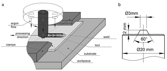
Figure 1.
Scheme of friction stir processing (a) and tool schematic (b).
The superalloy tool had a 2 mm length pin and a 20 mm diameter shoulder (Figure 1b). It was made of as-cast ZhS6U Ni-based superalloy of composition presented in Table 1. This alloy is an analogue of the Mar-M247 alloy. The tool was made using the lathe turning from a cylindrical billet.

Table 1.
Element composition of ZhS6U alloy (wt%).
The workpieces were made of 2.5 mm thick hot-rolled sheets of grade 2 titanium alloy. The initial composition of the alloy is presented in Table 2. The FSP was carried out in the direction parallel to the rolling direction. The processing was conducted using the process parameters at which the highest weld strength was achieved as reported elsewhere [34]. The axial force on the tool during both plunging (Fpl) and processing (Fpr) was maintained at 7848 N, the traverse speed (V) was 180 mm/min, and the tool rotation rate (ω) was 950 rpm. The total weld length was more than 2.5 m. Since the laboratory FSW machine was not attached with a liquid cooling system of, unlike industrial machines, the processing was carried out in successive 100 mm length passes to avoid the tool overheating. The process was stopped after each pass to cool the tool in air. The FSP tool was not cleaned in between the passes not to interfere with the conditions created in the usual FSW process.

Table 2.
Element composition of titanium alloy (wt%).
2.2. Investigative Techniques
Metallographic examinations were performed on both the tool and the weld materials. Samples of the processed metal were cut in a plane perpendicular to the weld. The tool material structure was examined in the cross section views. The views were obtained using polishing on abrasive papers and diamond pastes. Then, the processed titanium samples were etched in a 2% hydrofluoric acid solution for two minutes to reveal the microstructure and then washed in a 40% nitric acid solution. The tool microstructure was revealed with a reagent composed of 8 g CuSO4, 40 mL HCl, and 40 mL H2O.
Qualitative as well as quantitative analysis of the weld and tool microstructure was carried out using an Altami MET-1C metallographic microscope(Altami, St Petersburg, Russia) and a Microtrac SM 3000 scanning electron microscope (Nikkiso Co. Ltd., Tokyo, Japan) attached with an energy-dispersive X-ray microanalyzer (IXRF Systems). The worn surfaces of the tool were examined using an Olympus LEXT OLS4000 confocal microscope (Olympus, Tokyo, Japan). The tool was also photographed in the intervals between the passes to document its shape change.
Quasi-static tensile tests of the weld material were conducted in a UTC 110M-100 testing machine (Testsystems, Ivanovo, Russia) at room temperature. Flat specimens for mechanical tests were cut from stirring zone with their tensile axis coincided with the seam centerline (Figure 2). Such a test scheme was used to study the processed metal strength and thus evaluate the FSP efficiency. The base metal tensile test samples were used as reference ones. The loading rate was 1 mm/s according to the standard [35]. Microhardness numbers were obtained to evaluate the local hardness in the stir zone and in the base metal. Microhardness tester Duramin5 (Struers, Ballerup, Denmark) at 100 g load and dwell time 10 s was used.
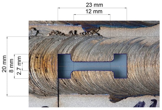
Figure 2.
Scheme of a tensile test specimen cut from the weld zone.
3. Results and Discussion
3.1. Tool Wear
The general views of the tool at different stages of the experiment are shown in optical images in Figure 3. One can see, that the tool worn surfaces are covered with an adherent layer of oxidized titanium. The edges of the pin and the shoulder are the most severely worn places during the processing. After processing the 1105 mm length, the pin shape is still conical and the depression is not observed (Figure 3b). Further processing results in gradual changing the pin shape from conical to nearly cylindrical one. A circular shape depression is gradually formed on the shoulder around the base of the pin in the course of processing.
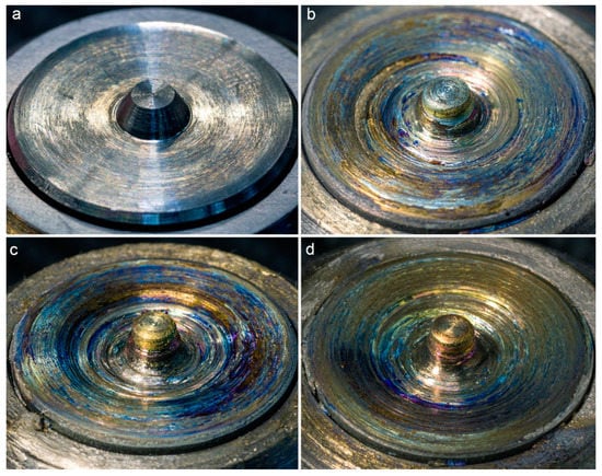
Figure 3.
General view of the tool before friction stir processing (FSP) (a), after traversing 1105 mm (b), 2335 mm (c), and 2755 mm (d).
Figure 4 shows typical 3D images of the tool worn surfaces before processing and after traversing 2755 mm. The surface morphology changed significantly. The adherent layers are represented by ridges generally oriented along the direction of rotation, with sparse pits formed due to adhesion and detachment of the transfer layer during processing. Despite the fact that the maximum wear of the shoulder is observed closer to the pin, there are no regular morphological features other than the fact that the shoulder roughness is higher in this area. In particular, the roughness of the pin tip surface after FSP was Ra = 15.6 μm, the average shoulder roughness was Ra = 13.6 μm, and the shoulder roughness around the pin was Ra = 26.2 μm (the pin and shoulder roughness before processing was Ra = 1.55 and Ra = 1.15 μm, respectively).
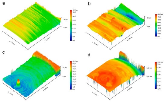
Figure 4.
Typical 3D images of the surface morphology of the tool shoulder (a) and pin (c) before processing and the shoulder (b) and pin (d) after traversing 2755 mm.
Figure 5 shows an SEM backscattered-electron (BSE) image of the tool worn surface after traversing 2755 mm and energy-dispersive X-ray spectroscopy (EDX) maps of Ti and W. Lighter band areas in the SEM BSE image correspond to the metal enriched with the tool material elements. It is suggested that the transfer layer was oxidized, embrittled, and detached from the tool surface when retracted from the titanium and no more protected by the argon. Therefore, this layer’s fragments may be easily detached during the next FSP pass. Tungsten is also observed in deposited titanium layers, indicating the diffusion of the tool elements into the transfer layer.
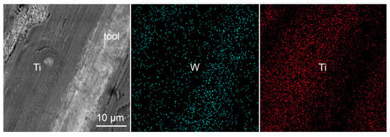
Figure 5.
SEM BSE image of the tool friction surface after traversing 2755 mm and EDX maps of Ti and W.
The axial cross-sectional view of the tool after traversing 2755 mm is shown in Figure 6 with superimposed drawing of the initial tool geometry. The highest wear is observed in the shoulder region at the base of the pin. The initial profile height loss in this zone is as high as 1 mm. The shoulder region closer to the edge is less worn so that its height loss was 0.25 mm. The pin height remained unchanged. In our opinion, such a non-uniform wear type may be of consequences as follows. Firstly, the reduced diameter at the base of the pin can lead to insufficient heat production because of lower friction velocity and hence to poor stirring. Secondly, the pin height does not change with the shoulder wear and therefore the tool may plunge deeper into the material. As a result, the pin can come into contact with the substrate and stick to it, or the substrate material can be introduced into the stirring zone.

Figure 6.
Axial cross-sectional view of the tool after traversing 2755 mm with superimposed drawing of the initial tool geometry.
Costa et al. [31], despite a different pin geometry, observed a similar wear pattern of a tool from a similar Mar-M247 alloy. The authors explained the wear behavior by material overheating that causes recrystallization of the alloy, carbide formation, and oxygen diffusion, which led to cracking of the surface layers and adhesive wear. The tool damage was avoided, as reported, using the argon shielding. However, there is no explanation why the maximum wear occurs closer to the tool axis. Formation of the annular depression around the pin was explained by Liu et al. [36] using the contact melting theory when they observed a similar concavity formed by friction in the center of a coating rod after deposition. Despite the fact that the friction velocity decreases closer to the center, heat transfer is impeded in this region, as the thermal energy mainly flows from the outer radius inwards and outwards. Therefore, the rod center becomes the point where the energy is concentrated and a quasi-liquid layer is formed. That is why the wear in the center is maximum. Such an explanation seems to hold good for the case of tool wear in FSP. However, as shown [31], the formation of a depression was avoided simply by using argon shielding, which could not greatly affect the heat transfer conditions. Nevertheless, contact melting might explain the fact that the surface layer material was recrystallized.
Generally, the heat-resistant superalloy tool wear is very specific in the case of welding on titanium. For instance, in FSW with steel tool on aluminum alloys the most severe wear is experienced by the pin’s end. It was shown [37] even that the pin end experienced plastic deformation. The similar wear pattern was observed on the H13 tool after welding on CuCrZr alloy [38]. FSW on Ti-6Al-4V carried out using similar configuration tools made of other materials also demonstrated different type of wear [16]. In particular, a W-La tool experienced severe plastic deformation while those made of WC-Co demonstrated brittle fracture.
An indication of the adhesive wear mechanism can be the diffusion of the tool elements into the transfer layer that remained on the friction surface after processing. Figure 7 shows an SEM image of the tool axial section and EDX maps of Ti and tool elements. The maps demonstrate that the main elements of the tool diffuse into the adherent titanium layer. The diffusion of Al is especially high. However, there is almost no titanium in the tool material. This is probably due to the fact that titanium rich layers of the tool are immediately removed during processing. Yet, the observed diffusion may be evidence of adhesive wear.
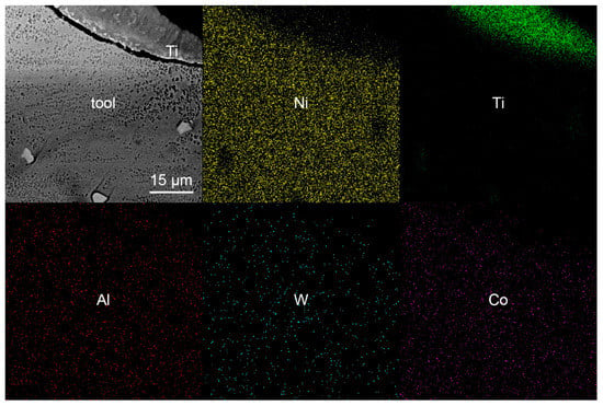
Figure 7.
SEM image of the tool axial section and EDX maps of Ti and tool elements.
3.2. Structure of the Tool
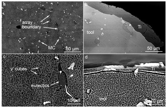
According to metallographic images of the tool and the base ZhS6U alloy (Figure 8), the structure at this scale is represented by arrays of γ-phase dendrites. The high-contrast bright objects at the array boundaries are carbides characteristic of the alloy. The shape of the arrays generally tends to be equiaxed after FSP both in the base material and in the tool. As a result of the thermal effect, the structural elements grew considerably. The size of dendritic arrays, the primary and secondary dendrite arm spacings increased by a factor of 3. The measurement results are given in Table 3. It is characteristic that the structure changed uniformly throughout the tool. The array sizes and the dendrite arm spacings did not change as well as the amount of carbides did not increase in the subsurface region. The thickness of the adherent titanium layer on the tool is in the range of 30–80 μm, which is consistent with the surface morphology measurements. The change in contrast near the worn surface is caused by over-etching due to surface tension at the edge of the specimen when it was removed from the reagent.
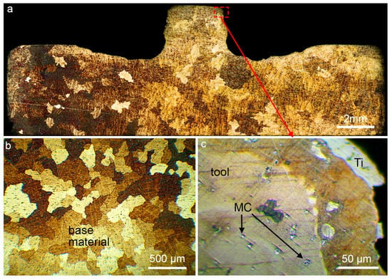
Figure 8.
Metallographic images of the tool axial section after traversing 2755 mm (a,c) and the base ZhS6U alloy (b).

Table 3.
Characteristics of microstructural elements.
Figure 9 shows SEM BSE images of the base ZhS6U alloy structure and the tool structure. The images highlight the dendritic array boundaries decorated with eutectics and carbides of heavy metals, which mainly include Ti, W, Mo, and Nb [39]. In addition, irregular carbides and eutectics are often located in the interdendritic spaces [40]. At a finer level, the alloy structure is represented by γ’-phase cubes [41]. The measurement results for these structural elements show that the carbide volume fraction decreased slightly after FSP (Table 3), while the average carbide size increased by a factor of more than 1.5. The carbide size measurements have low accuracy because of the large size scatter in the range of 0.7–5 µm. The size change of carbides at their almost constant volume fraction is related to the coagulation of particles that occurs as dendrites grow during recrystallization. The size of γ’ cubes remained unchanged as a result of the thermal effect. The material below the tool friction surface as well as below the adherent titanium layer also revealed no specific feature. Figure 9b was obtained in the same region as the optical image of Figure 8c.
3.3. Quality of Friction Stir Processing
The processing quality here refers to the structure of the weld and its mechanical properties. Figure 10 shows the cross-sectional metallographic images of FSPed material in different regions: at distances 5, 560, and 2755 mm from the starting point of the weld. According to metallographic analysis, the general view of the weld and the characteristic view of structural zones in all processing regions are the same for all samples. The weld structure exhibits two typical zones: stir zone (SZ) consisting of small recrystallized grains of titanium alloy, and thermomechanically affected zone (TMAZ). The rest is the base material. The heat affected zone, which is usually located between the base metal and TMAZ, is often absent or not detected in titanium alloys. The TMAZ in FSPed titanium alloy is narrow as compared to that of obtained on materials, with the average thickness of about 0.25 mm. The geometry of the structural zones is generally symmetrical about the weld axis. Their shapes in different processing regions differ slightly. The SZ area gradually decreases with the tool wear: from 11.11 mm2 in the first sample to 8.03 mm2 in the last one. This occurs because the pin diameter is reduced as the tool is worn.
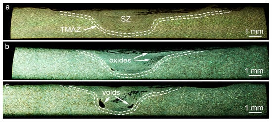
Figure 10.
Cross-sectional metallographic images of FSPed material at 5 mm (a), 560 mm (b), and 2755 mm (c) from the weld start.
Samples for metallographic analysis were cut approximately every 250 mm along the weld length. The sample cut at a distance of 5 mm from the starting point has no discontinuities and appears typical of the FSPed metals. The first discontinuities are observed in the sample cut at 560 mm distance, at the SZ boundary on the retreating side of the weld. These discontinuities grew with the processing time as well as new ones formed, including those on the advancing side. A sharp increase in the number of discontinuities is observed at ≈2300 mm distance. There are also oxides in the SZ, despite the fact that the processing was conducted in argon. As in the case with discontinuities, the first samples exhibit almost no traces of oxides, which become more pronounced with distance. The formation of discontinuities is associated specifically with the tool wear, because the tool geometry change induces a change in the mass transfer trajectory. At constant processing parameters, this leads to a change in heat production and deformation and, as a consequence, to non-optimal stirring conditions. The gradual emergence of oxides in the weld is presumably due to oxide accumulation on the tool surface. When processing is stopped, the tool is retracted from the material and the argon shield is removed. The extracted FSP tool is always covered with a layer of the processed metal. In our case, the adherent transfer layer was actively oxidized at high temperature in air and could be introduced into the material during the next pass. Oxides are gradually stirred into the material during processing together with the already present defects. The oxidized metal is located at the edges of the transfer layers, due to which the cohesive forces between the layers are reduced and delamination occurs. Ultimately, the oxide regions become the sites of discontinuity formation. The total area of all discontinuities in the cross section was 0.07 mm2 at 5 mm distance, 0.15 mm2 at 560 mm, and 0.79 mm2 at 2755 mm.
Friction stir processing resulted in a recrystallized and considerably refined alloy structure, which is typical of FSP [42]. In particular, the SZ exhibits equiaxed solid solution grains of size 8 ± 2 μm (Figure 11a), while the base metal consisted of 54 ± 11 μm grains. The grain size in the SZ did not change with tool wear. The solid solution grains also exhibit banded structures similar to twins. Twinning is not typical of commercially pure titanium under ordinary conditions, but it occurs at low temperatures, e.g., in cold rolling [43], and/or at high strain rates. The twining was earlier observed in FSWed on commercially pure titanium [44] and explained by the lack of slip systems at a high strain rate.
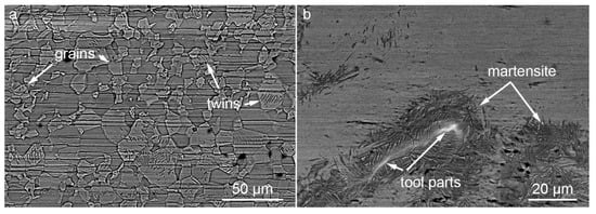
Figure 11.
SEM images of the grain structure in the stir zone (SZ) (a) and oxidized regions (b).
The admixed oxides in the SZ are surrounded by martensite (Figure 11b), which is not characteristic of the studied alloy. Commercially pure titanium belongs to α-phase materials. As shown [45], heating above the phase transition temperature and rapid cooling (>100 °C/s) can cause the formation of α’ martensite from the melt under high thermal stresses. However, such temperatures and cooling rates are not achieved during FSP, while high stresses are present. Therefore, the occurrence of martensite may be explained by alloying with the tool metal. The oxidized martensitic regions contain tool particles stirred during wear together with transfer layers into the processed metal. As a result of diffusion, these particles dope the surrounding material with W, Al, Ni, and other atoms and induce the formation of martensite.
Figure 12 shows the results of quasi-static tensile tests for the SZ of specimens. The ultimate tensile strength of the processed material first increased by ≈25% as compared to the base metal strength of 350 MPa. With tool wear, the tensile strength of the specimens decreased and reached 375 MPa after traversing 2700 mm, which is by ≈7% higher than the base metal strength. A sharp decrease in strength is observed at 500 mm distance corresponding to the formation of first macrodefects. The second sharp drop at 2300 mm is also related to a drastic increase in the number of discontinuities. Therefore, the strength reduction is associated primarily with the growth of defects during tool wear, which leads to insufficient heating and poor stirring of the material. Despite the weld strength exceeds the base alloy strength, this result is not satisfactory, because the presence of macrodefects makes the weld performance unreliable under fatigue loading. The maximum elongation at fracture diminished by a factor of 2. The processed material showed the plasticity level to be independent of the FSW tool wear. The same was true for the stir zone microhardness numbers, which were 1.5 ± 0.1 GPa, 1.4 ± 0.1 GPa, and 1.6 ± 0.1 GPa for 20 mm, 500 mm, and 2700 mm processed length, respectively. The base metal microhardness was 1.3 ± 0.1 GPa. Such a moderate hardening was the result of severe plastic deformation during FSP.
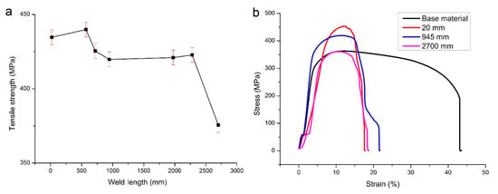
Figure 12.
Dependence of the weld strength on the tool wear (a) and stress–strain curves of friction stir processed welds at different weld lengths (b).
The formation of defects during tool wear can be avoided by changing the processing parameters, e.g., the axial load. An increase in the load will lead to greater heat production, enhanced adhesion, and therefore better stirring. Although this method is complicated, it may be a temporary solution. The tool life can be extended by using liquid cooling on the back side of the tool to minimize the contact melting and recrystallization effects. One more cause of softening is an increase in the amount of oxides introduced into the SZ from the tool. This problem can be solved by blowing the tool with argon after retracting it from titanium. The given solution requires a large consumption of argon, but it can help avoiding the oxidation of titanium transferred on the friction surface of the tool.
4. Conclusions
This study explored the durability of a ZhS6U Ni-based superalloy tool in FSP of commercially pure titanium and the effect of the tool wear on the weld quality. The total length of the weld produced by the tool without failure comprised 2755 mm. The highest wear was observed at the base of the pin which lost its conical shape during processing and a 1 mm deep circular depression formed in the shoulder near the pin. Analysis of the adherent transfer layer on the tool retracted from titanium revealed the presence of ZhS6U alloy constituents, which is indicative of diffusion during FSP. Thus, the wear occurs by an adhesive mechanism. It was also found that the tool overheating during FSP leads to the recrystallization of ZhS6U alloy. In particular, the size of dendritic arrays as well as the primary and secondary dendrite arm spacings increased by a factor of 3. The size of heavy metal carbides increased almost twice, while their volume fraction did not change. The size of γ’ cubes also remained unchanged.
The tool wear resulted in macrostructural changes in the processed material. The SZ area was reduced, while the number and size of macrodefects increased with the tool wear. The defects included discontinuities caused by insufficient heating as well as oxide particles admixed. The oxides formed on the tool after it was retracted from titanium and then were stirred into the workpiece during the next pass. As a result of FSP, commercially pure titanium recrystallized. The solid solution grain size decreased by a factor of ≈6.5, inducing significant hardening. The first FSP samples had tensile strength of ≈435 MPa, which was 25% higher than that of the base metal (350 MPa). After traversing 2700 mm the tensile strength decreased to 375 MPa due to the increased number and size of macrodefects.
In general, ZhS6U alloy proved to be suitable for making the FSP tool for titanium. However, its use requires liquid cooling of the tool during FSP to avoid overheating. Argon shielding is also needed to avoid oxidation of the adherent transfer layer on the extracted tool while it is cooled.
Author Contributions
Conceptualization, A.E. and V.R.; investigation, A.A., A.E., and A.F.; resources, E.K. and V.R.; writing—original draft preparation, A.A. and A.E.; writing—review and editing, E.K. All authors have read and agreed to the published version of the manuscript.
Funding
The reported study was funded by RFBR, Project No. 19-33-90187. SEM investigations was performed under the government statement of work for ISPMS SB RAS Project No. III.23.2.4.
Conflicts of Interest
The authors declare no conflict of interest.
References
- Peters, M.; Hemptenmacher, J.; Kumpfert, J.; Leyens, C. Structure and Properties of Titanium and Titanium Alloys. In Titanium and Titanium Alloys; Leyens, C., Peters, M., Eds.; Wiley-VCH: Weinheim, Germany, 2005. [Google Scholar]
- Sizova, O.; Shlyakhova, G.; Kolubaev, A.; Kolubaev, E.A.; Psakhie, S.G.; Rudenskii, G.; Chernyavsky, A.G.; Lopota, V. Microstructure Features of Aluminum Alloys Welded Joint Obtained by Friction Stir Welding. Adv. Mater. Res. 2013, 872, 174–179. [Google Scholar] [CrossRef]
- Eliseev, A.A.; Fortuna, S.V.; Kalashnikova, T.A.; Chumaevskii, A.V.; Kolubaev, E.A. Structural Phase Evolution in Ultrasonic-Assisted Friction Stir Welded 2195 Aluminum Alloy Joints. Russ. Phys. J. 2017, 60, 1022–1026. [Google Scholar] [CrossRef]
- Tarasov, S.Y.; Rubtsov, V.E.; Kolubaev, E.A. A proposed diffusion-controlled wear mechanism of alloy steel friction stir welding (FSW) tools used on an aluminum alloy. Wear 2014, 318, 130–134. [Google Scholar] [CrossRef]
- Sato, Y.S.; Park, S.H.C.; Matsunaga, A.; Honda, A.; Kokawa, H. Novel production for highly formable Mg alloy plate. J. Mater. Sci. 2005, 3, 637–642. [Google Scholar] [CrossRef]
- Kalashnikova, T.A.; Kalashnikov, K.N.; Shvedov, M.A.; Vasilyev, P.A. Structure and properties of copper compensator joints obtained by hybrid friction stir welding technology. Met. Work. Mater. Sci. 2019, 21, 85–93. [Google Scholar] [CrossRef]
- Kalashnikova, T.A.; Gusarova, A.V.; Chumaevskii, A.V.; Knyazhev, E.O.; Shvedov, M.A.; Vasilyev, P.A. Regularities of composite materials formation using additive electron-beam technology, friction stir welding and friction stir processing. Met. Work. Mater. Sci. 2019, 21, 94–112. [Google Scholar] [CrossRef]
- Mishra, R.S.; Ma, Z.Y. Friction stir welding and processing. Mater. Sci. Eng. R 2005, 50, 1–78. [Google Scholar] [CrossRef]
- Nandan, R.; Debroy, T.; Bhadeshia, H. Recent advances in friction-stir welding—Process, weldment structure and properties. Prog. Mater. Sci. 2008, 53, 980–1023. [Google Scholar] [CrossRef]
- Farias, A.; Batalha, G.F.; Prados, E.F.; Magnabosco, R.; Delijaicov, S. Tool wear evaluations in friction stir processing of commercial titanium Ti–6Al–4V. Wear 2013, 302, 1327–1333. [Google Scholar] [CrossRef]
- Liu, H.J.; Zhou, L.; Liu, Q.W. Microstructural evolution mechanism of hydrogenated Ti–6Al–4V in the friction stir welding and post-weld dehydrogenation process. Scr. Mater. 2009, 61, 1008–1011. [Google Scholar] [CrossRef]
- Zhou, L.; Liu, H.J. Effect of 0.3 wt.% hydrogen addition on microstructural evolution of Ti–6Al–4V alloy in the friction stir welding and post-weld dehydrogenation process. Mater. Charact. 2011, 62, 1036–1041. [Google Scholar] [CrossRef]
- Wu, L.H.; Xue, P.; Xiao, B.L.; Ma, Z.Y. Achieving superior low-temperature superplasticity for lamellar microstructure in nugget of a friction stir welded Ti-6Al-4V joint. Scripta Mater. 2016, 122, 26–30. [Google Scholar] [CrossRef]
- Li, B.; Shen, Y.; Hu, W.; Luo, L. Surface modification of Ti–6Al–4V alloy via friction-stir processing: Microstructure evolution and dry sliding wear performance. Surf. Coat. Technol. 2014, 239, 160–170. [Google Scholar] [CrossRef]
- Pilchak, A.L.; Tang, W.; Sahiner, H.; Reynolds, A.P.; Williams, J.C. Microstructure Evolution during Friction Stir Welding of Mill-Annealed Ti-6Al-4V. Metall. Mater. Trans. A 2010, 42, 745–762. [Google Scholar] [CrossRef]
- Wang, J.; Su, J.; Mishra, R.S.; Xu, R.; Baumann, J.A. A Preliminary Study of Deformation Behavior of Friction Stir Welded Ti-6Al-4V. J. Mater. Eng. Perform. 2014, 23, 3027–3033. [Google Scholar] [CrossRef]
- Lippold, J.C.; Livingston, J.J. Microstructure Evolution During Friction Stir Processing and Hot Torsion Simulation of Ti-6Al-4V. Metall. Mater. Trans. A 2013, 44, 3815–3825. [Google Scholar] [CrossRef]
- Fall, A.; Fesharaki, M.; Khodabandeh, A.; Jahazi, M. Tool Wear Characteristics and Effect on Microstructure in Ti-6Al-4V Friction Stir Welded Joints. Metals 2016, 6, 275. [Google Scholar] [CrossRef]
- Edwards, P.D.; Ramulu, M. Comparative study of fatigue and fracture in friction stir and electron beam welds of 24mm thick titanium alloy Ti-6Al-4V. Fatigue Fract. Eng Mater. Struct. 2016, 39, 1226–1240. [Google Scholar] [CrossRef]
- Muzvidziwa, M.; Okazaki, M.; Suzuki, K.; Hirano, S. Role of microstructure on the fatigue crack propagation behavior of a friction stir welded Ti–6Al–4V. Mater. Sci. Eng. A 2016, 652, 59–68. [Google Scholar] [CrossRef]
- Yoon, S.; Ueji, R.; Fujii, H. Effect of initial microstructure on Ti–6Al–4V joint by friction stir welding. Mater. Des. 2015, 88, 1269–1276. [Google Scholar] [CrossRef]
- Sato, Y.S.; Susukida, S.; Kokawa, H.; Omori, T.; Ishida, K.; Imano, S.; Park, S.H.C.; Sugimoto, I.; Hirano, S. Wear of cobalt-based alloy tool during friction stir welding of Ti-6Al-4V alloy. In Proceedings of the 11th International Symposium on FrictionStir Welding, Cambridge, UK, 17–19 May 2016. [Google Scholar]
- Mironov, S.; Zhang, Y.; Sato, Y.S.; Kokawa, H. Crystallography of transformed b microstructure in friction stir welded Ti–6Al–4V alloy. Scr. Mater. 2008, 59, 511–514. [Google Scholar] [CrossRef]
- Mironov, S.; Zhang, Y.; Sato, Y.S.; Kokawa, H. Development of grain structure in b-phase field during friction stir welding of Ti–6Al–4V alloy. Scr. Mater. 2008, 59, 27–30. [Google Scholar] [CrossRef]
- Zhang, Y.; Sato, Y.S.; Kokawa, H.; Park, S.H.C.; Hirano, S. Microstructural characteristics and mechanical properties of Ti–6Al–4V friction stir welds. Mater. Sci. Eng. A 2008, 485, 448–455. [Google Scholar] [CrossRef]
- Wu, L.H.; Wang, D.; Xiao, B.L.; Ma, Z.Y. Tool wear and its effect on microstructure and properties of friction stir processed Ti–6Al–4V. Mater. Chem. Phys. 2014, 146, 512–522. [Google Scholar] [CrossRef]
- Zhang, Y.; Sato, Y.S.; Kokawa, H.; Park, S.H.C.; Hirano, S. Stir zone microstructure of commercial purity titanium friction stir welded using pcBN tool. Mater. Sci. Eng. A 2008, 488, 25–30. [Google Scholar] [CrossRef]
- Rai, R.; De, A.; Bhadeshia, H.K.D.H.; DebRoy, T. Review: Friction stir welding tools. Sci. Technol. Weld. Join. 2011, 16, 325–342. [Google Scholar] [CrossRef]
- Mironov, S.; Sato, Y.S.; Kokawa, H. Friction-stir welding and processing of Ti-6Al-4V titanium alloy: A review. J. Mater. Sci. Technol. 2018, 34, 58–72. [Google Scholar] [CrossRef]
- Amirov, A.I.; Utyaganova, V.R.; Beloborodov, V.A.; Eliseev, A.A. Formation features of a welding joint of alloy Grade2 by the friction stir welding using temperature resistant tools. Met. Work. Mater. Sci. 2019, 21, 72–82. [Google Scholar] [CrossRef]
- Costa, A.M.S.; Oliveira, J.P.; Pereira, V.F.; Nunes, C.A.; Ramirez, A.J.; Tschiptschin, A.P. Ni-based Mar-M247 superalloy as a friction stir processing tool. J. Mater. Process. Tech. 2018, 262, 605–614. [Google Scholar] [CrossRef]
- Nakazawa, T.; Sato, Y.S.; Kokawa, H.; Ishida, K.; Omori, T.; Tanaka, K.; Sakairi, K. Friction Stir Welding of Steels Using a Tool Made of Iridium-Containing Nickel Base Superalloy. In Friction Stir Welding and Processing VIII; Mishra, R.S., Mahoney, M.W., Sato, Y., Hovanski, Y., Eds.; Springer: Cham, Switzerland, 2015. [Google Scholar]
- Kablov, E.N.; Petrushin, N.V.; Parfenovich, P.I. Design of castable refractory nickel alloys with polycrystalline structure. Met. Sci. Heat Treat. 2018, 60, 106–114. [Google Scholar] [CrossRef]
- Amirov, A.I.; Eliseev, A.A.; Rubtsov, V.E.; Utyaganova, V.R. Butt friction stir welding of commercially pure titanium by the tool from a heat-resistant nickel alloy. AIP Conf. Proc. 2019, 2167, 020016. [Google Scholar]
- ISO 6892-1-2016 Metallic Materials. Tensile Testing. Part 1: Method of Test at Room Temperature; CENELEC: Brussel, Belgium, 2016. [Google Scholar]
- Liu, X.M.; Zou, Z.D.; Zhang, Y.H.; Qu, S.Y.; Wang, X.H. Transferring mechanism of the coating rod in friction surfacing. Surf. Coat. Technol. 2008, 202, 1889–1894. [Google Scholar] [CrossRef]
- Bevilacqua, M.; Ciarapica, F.; Forcellese, A.; Simoncini, M. Comparison among the environmental impact of solid state and fusion welding processes in joining an aluminium alloy. Proc. Inst. Mech. Eng. Part B J. Eng. Manuf. 2020, 234, 140–156. [Google Scholar] [CrossRef]
- Sahlot, P.; Jha, K.; Dey, G.K.; Arora, A. Quantitative wear analysis of H13 steel tool during friction stir welding of Cu-0.8%Cr-0.1%Zr alloy. Wear 2017, 378–379, 82–89. [Google Scholar] [CrossRef]
- Zhou, T.; Ding, H.; Ma, X.; Feng, W.; Zhao, H.; Li, A.; Meng, Y.; Zhang, H. A comparison study of the thermal fatigue properties of three Ni-based cast superalloys cycled from 20 to 1100 °C. Adv. Eng. Mater. 2019, 21, 1900054. [Google Scholar] [CrossRef]
- Wang, L.N.; Sun, X.F.; Guan, H.R. Effect of melt heat treatment on MC carbide formation in nickel-based superalloy K465. Results Phys. 2017, 7, 2111–2117. [Google Scholar] [CrossRef]
- Jonšta, P.; Vlčková, I.; Jonšta, Z.; Podhorná, B. Materialographic Analysis of MAR M-247 Superalloy. Key Eng. Mater. 2015, 647, 66–71. [Google Scholar] [CrossRef]
- Kalashnikov, K.N.; Kalashnikova, T.A.; Chumaevskii, A.V.; Ivanov, A.N. Production of materials with ultrafine-grained structure of aluminum alloy by friction stir processing. J. Phys. Conf. Ser. 2018, 1115, 042048. [Google Scholar] [CrossRef]
- Zherebtsov, S.V.; Dyakonov, G.S.; Salishchev, G.A.; Salem, A.A.; Semiatin, S.L. The influence of grain size on twinning and microstructure refinement during cold rolling of commercial-purity titanium. Metall. Mater. Trans. A 2016, 47, 5101–5113. [Google Scholar] [CrossRef]
- Lee, W.-B.; Lee, C.-Y.; Chang, W.-S.; Yeon, Y.-M.; Jung, S.-B. Microstructural investigation of friction stir welded pure titanium. Mater. Lett. 2005, 59, 3315–3318. [Google Scholar] [CrossRef]
- Zhang, X.D.; Hao, S.Z.; Li, X.N.; Dong, C.; Grosdidier, T. Surface modification of pure titanium by pulsed electron beam. Appl. Surf. Sci. 2011, 257, 5899–5902. [Google Scholar] [CrossRef]
© 2020 by the authors. Licensee MDPI, Basel, Switzerland. This article is an open access article distributed under the terms and conditions of the Creative Commons Attribution (CC BY) license (http://creativecommons.org/licenses/by/4.0/).
