1. Introduction
The hybrid laminate CAPAAL (carbon fibre-reinforced polyamide/aluminium foil laminate) [
1] is a build-up of metals and thermoplastic-based carbon fibre-reinforced plastics (FRPs), which is an attractive alternative to those based on thermosetting matrix systems like CARALL [
2] (carbon-reinforced aluminium laminate), because they can easily be shaped by thermoforming [
3] and consolidated in shorter cycle times. A significant advantage of the layered design is the demonstrably better fatigue behaviour than pure aluminium through the fibre bridging effect [
2] and increased damage resistance compared to FRP. The composition of a hybrid laminate is described by the number of metal (N
Metal) and FRP layers (N
FRP) as “N
Metal/N
FRP”. Typically, hybrid laminates are constructed in a multiple changing arrangement of metal and FRP layers with the layer structure description of 2/1, 3/2, or 4/3, etc.
An essential aspect of CAPAAL and other fibre-metal laminates (FML) is the surface treatment of the metal component since it impacts the interface strength between the metal component and FRP. Regarding the criteria, such as suitability for large series production [
4] and interlaminar shear strength [
5], mechanical blasting has proven to be appropriate in previous work. It has been found that mechanical adhesion is not alone responsible for high shear strength due to increased roughness. In [
5] different strong chemical bonds of the surface states are applied. Narbon et al. show that roughness differences caused by mechanical treatment (grinding) or chemical etching (HCl) do not have a strong influence on the surface energy of AA6082, but they always measured an increase in comparison to the untreated sheet [
6]. The aluminium surface treatment possesses a clear influence on the quasi-static tensile properties of the laminate, but significantly more in fatigue tests where anodization and phosphating of the aluminium surface led to the highest fatigue lifetimes [
7].
Reyes et al. were able to determine a linear increase in strength with increasing glass fibre-reinforced plastic (GFRP) content in tensile tests independent of the layer structure 2/1, 3/2, or 4/3. The Young’s modulus, on the other hand, decreased linearly [
8]. The relationships are following the rule of mixture and their values depend on the properties of the base materials, which was also shown by Sun et al. [
9] for titanium/carbon-fibre epoxy laminates. It can be expected that the bending behaviour of the laminates will behave significantly different since the distance of the FRP from the neutral fibre has an influence. Bellin et al. [
10,
11] showed that for inverted layer structures 1/2 and 2/3 of CARALL the flexural strength, strain, and modulus are decreased for latter, if the fractions of laminate partners and overall thickness of the laminate are held constant. All investigated specimens showed composite tensile failure with delamination occurring in-between the fibre-metal interface in specimens without additional adhesive layers. The changes in mechanical properties were confirmed by Cortés et al. [
12], which investigated a 2/1 layer structure made of magnesium alloy and thermoplastic GFRP in terms of variating FRP content, and also by Wu et al. [
13] in investigations from 2/1 with up to an 8/7 layer structures of laminates containing magnesium alloys and carbon fibre-reinforced plastic (CFRP).
Fatigue bending of CAPAAL with layer structures 2/1 und 3/2 under elastic loading of the laminate, which is below the fatigue limit, withstands one million load cycles without any measurable damage in the individual subcomponents. Higher loads are leading to crack propagation inside the aluminium top sheet, whereas only the highest loads applied induced additional damage occurrence inside the thermoplastic matrix [
14].
To extend previous research on the influence of the layer structure and metal volume content on the mechanical properties of hybrid laminates like CAPAAL more investigations, using expanded metrological instrumentation for a detailed understanding while not relying on just one specific loading case, need to be conducted. Thus, this study provides a comprehensive overview about the impact of the layer structure and metal volume content on the mechanical properties under bending and fatigue tension/tension loading for a hybrid laminate based on aluminium and carbon fibre-reinforced polyamide 6, containing a glass fibre-reinforced graded layer. The aluminium surface treatment and thereby implied interlaminar interface changes between the aluminium surface conditions and the FRP are considered as important factors as well. The aim of this study is gathering a wide impression about the structural differences and its importance regarding load capacity and laminate integrity for high and lasting mechanical performance, to establish fundamental knowledge, which is needed for, e.g., design of components.
Author Contributions
Conceptualization, M.T. and S.M.; Methodology, M.T. and S.M.; Validation, M.T. and S.M.; Investigation, M.T. and S.M.; Resources, M.T. and S.M.; Data Curation, M.T. and S.M.; Writing—Original Draft Preparation, M.T. and S.M.; Writing—Review & Editing, F.W. and G.W.; Visualization, M.T. and S.M.; Supervision, F.W. and G.W.; Project Administration, M.T. and S.M.; Funding Acquisition, F.W. and G.W. All authors have read and agreed to the published version of the manuscript.
Funding
The authors thank the German Research Foundation (Deutsche Forschungsgemeinschaft, DFG) for its financial support within the research project “Mechanism-correlated characterization of the deformation and damage behaviour of thermoplastic-based fibre metal laminates for property-oriented process development” (WA 1665/9-1, WA 1672/56-1).
Acknowledgments
The authors acknowledge Martin Risthaus from Evonic for providing surface treatment, Barbara Meier for supporting the contact angle measurements on treated surfaces as well as Marco Fischer for supporting the experimental tests in Chemnitz. Further on the authors acknowledge financial support by German Research Foundation (Deutsche Forschungsgemeinschaft, DFG).
Conflicts of Interest
The authors declare no conflict of interest.
References
- Wielage, B.; Nestler, D.; Steger, H.; Kroll, L.; Tröltzsch, J.; Nendel, S. CAPAAL and CAPET—New materials of high-strength, high-stiff hybrid laminates. In Integrated Systems, Design and Technology 2010; Springer: Berlin/Heidelberg, Germany, 2011; ISBN 978-3-642-17384-4. [Google Scholar]
- Lin, C.T.; Kao, P.W.; Yang, F.S. Fatigue behaviour of carbon fibre-reinforced aluminium laminates. Composites 1991, 22, 135–141. [Google Scholar] [CrossRef]
- Nestler, D.; Trautmann, M.; Zopp, C.; Tröltzsch, J.; Osiecki, T.; Nendel, S.; Wagner, G.; Kroll, L. Continuous film stacking and thermoforming process for hybrid CFRP/aluminium laminates. Procedia CIRP 2017, 66, 107–112. [Google Scholar] [CrossRef]
- Nestler, D.; Trautmann, M.; Nendel, S.; Wagner, G.; Kroll, L. Innovative hybrid laminates of aluminium alloy foils and fibre-reinforced thermoplastic layers. Mater. Sci. Eng. Technol. 2016, 47, 1121–1131. [Google Scholar] [CrossRef]
- Trautmann, M.; Mrzljak, S.; Walther, F.; Wagner, G. Influence of surface treatment on interfacial strength and tensile properties of thermoplastic based hybrid laminates. In Hybrid—Materials and Structures 2020—Proceedings. 4th International Conference Hybrid 2020 Materials and Structures, Web-Conference, Germany, 28–29 April; Hausmann, J.M., Siebert, M., von Hehl, A., Weidenmann, K.A., Eds.; DGM: Sankt Augustin, Germany, 2020. [Google Scholar]
- Narbon, J.J.; Moreno-Díaz, C.; Arenas, J.M. Influence of surface treatment on the surface energy of an aluminium substrate. Colloids Surf. A Physicochem. Eng. Asp. 2019, 560, 323–329. [Google Scholar] [CrossRef]
- Mrzljak, S.; Trautmann, M.; Wagner, G.; Walther, F. Influence of surface treatment on fatigue properties of thermoplastic-based hybrid laminates. In Hybrid—Materials and Structures 2020—Proceedings. 4th International Conference Hybrid 2020 Materials and Structures, Web-Conference, Germany, 28–29 April; Hausmann, J.M., Siebert, M., von Hehl, A., Weidenmann, K.A., Eds.; DGM: Sankt Augustin, Germany, 2020. [Google Scholar]
- Reyes, V.G.; Cantwell, W.J. The mechanical properties of fibre-metal laminates based on glass fibre reinforced polypropylene. Compos. Sci. Technol. 2000, 60, 1085–1094. [Google Scholar] [CrossRef]
- Sun, J.; Daliri, A.; Lu, G.; Ruan, D.; Lv, Y. Tensile failure of fibre-metal-laminates made of titanium and carbon-fibre/epoxy laminates. Mater. Des. 2019, 183, 108139. [Google Scholar] [CrossRef]
- Bellini, C.; Di Cocco, V.; Iacoviello, F.; Sorrentino, L. Experimental analysis of aluminium/carbon epoxy hybrid laminates under flexural load. Frat. Integrità Strutt. 2019, 13, 739–747. [Google Scholar] [CrossRef]
- Bellini, C.; Di Cocco, V.; Iacoviello, F.; Sorrentino, L. Performance evaluation of CFRP/Al fibre metal laminates with different structural characteristics. Compos. Struct. 2019, 225, 111117. [Google Scholar] [CrossRef]
- Cortés, P.; Cantwell, W.J. The fracture properties of a fibre–metal laminate based on magnesium alloy. Compos. Part B Eng. 2005, 37, 163–170. [Google Scholar] [CrossRef]
- Wu, X.; Pan, Y.; Wu, G.; Huang, Z.; Tian, R.; Sun, S. Flexural behaviour of CFRP/MG hybrid laminates with different layers thickness. Adv. Compos. Lett. 2017, 26, 168–172. [Google Scholar] [CrossRef]
- Zopp, C.; Dittes, A.; Nestler, D.; Scharf, I.; Kroll, L.; Lampke, T. Quasi-static and fatigue bending behaviour of a continuous fibre-reinforced thermoplastic/metal laminate. Compos. Part B Eng. 2019, 174, 107043. [Google Scholar] [CrossRef]
- Mrzljak, S.; Trautmann, M.; Wagner, G.; Walther, F. Influence of aluminium surface treatment on tensile and fatigue behaviour of thermoplastic-based hybrid laminates. Materials 2020, 13, 3080. [Google Scholar] [CrossRef] [PubMed]
- Schürmann, H. Konstruieren Mit Faser-Kunststoff-Verbunden, 2nd ed.; Springer: Berlin/Heidelberg, Germany, 2008; ISBN 978-3-540-72189-5. [Google Scholar]
- Kim, J.; Kim, H.-S.; Park, C.H. Contribution of surface energy and roughness to the wettability of polyamide 6 and polypropylene film in the plasma-induced process. Text. Res. J. 2015, 86, 461–471. [Google Scholar] [CrossRef]
- Park, S.Y.; Choi, W.J.; Choi, H.S.; Kwon, H. Effects of surface pre-treatment and void content on GLARE laminate process characteristics. J. Mater. Process. Technol. 2010, 210, 1008–1016. [Google Scholar] [CrossRef]
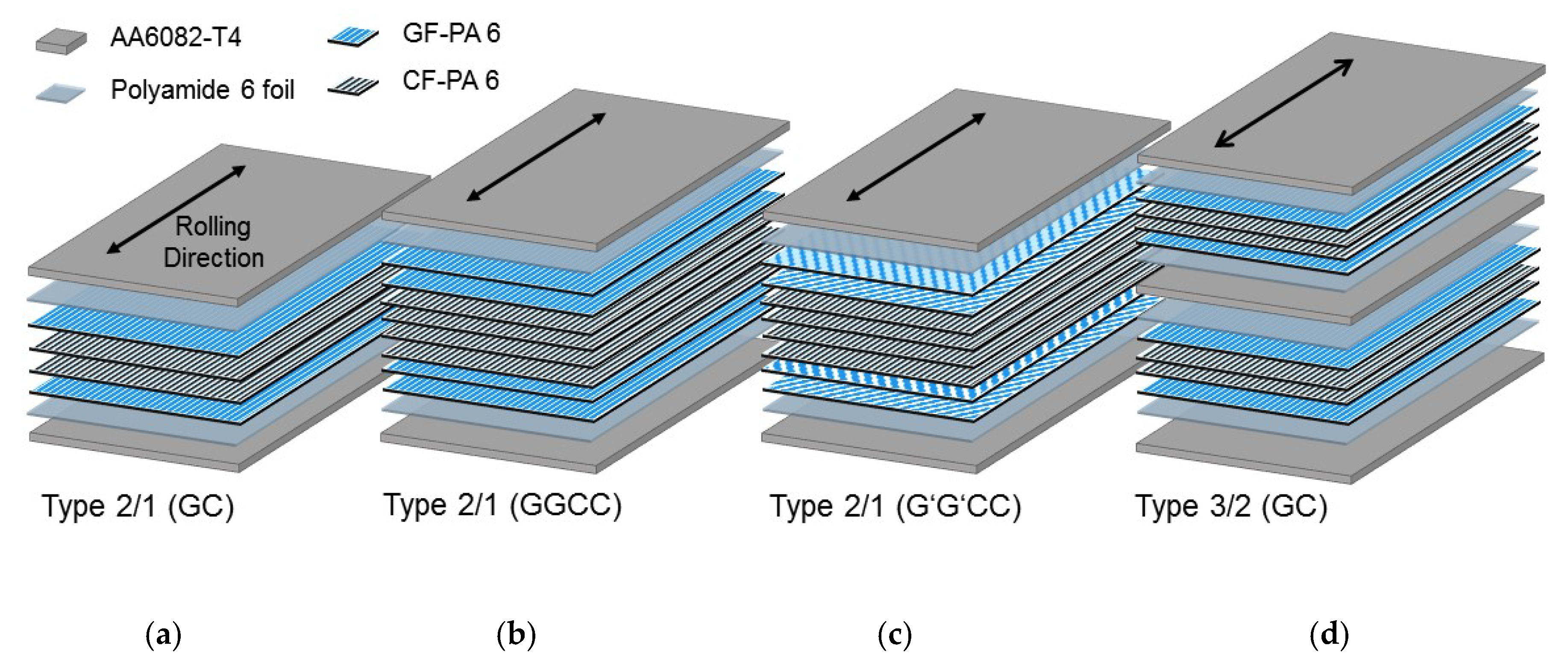
Figure 1.
Material composition of the hybrid laminates: (a) 2/1 (GC) with four fibre-reinforced plastic (FRP) layers, (b,c) 2/1 (GGCC) with eight FRP layers but different glass FRP (GFR-PA6 orientations (±45° for 2/1 (G′G′CC)), and (d) 3/2 with 2× four FRP layers between aluminium sheets.
Figure 2.
Cross section of the semi-finished FRP products: (a) glass and (b) carbon fibre-reinforced polyamide 6.
Figure 3.
(a) Dipping edge tool and (b) cycle of thermal pressing for the hybrid laminates.
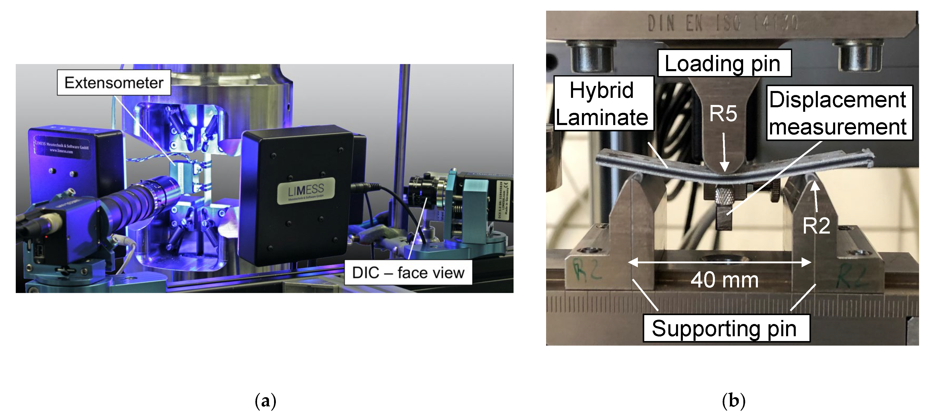
Figure 4.
(a) Instrumented tensile and fatigue testing setup containing the servo-hydraulic testing system, digital image correlation camera perpendicular to the specimen (face view), and tactile extensometer; (b) Three-point bending testing setup according DIN EN ISO 14125.
Figure 5.
Surface energy of treated aluminium alloy AA6082 and PA6 foil with dispersive and polar component. Absolute value of the polar component of surface energy is highlighted through digits.
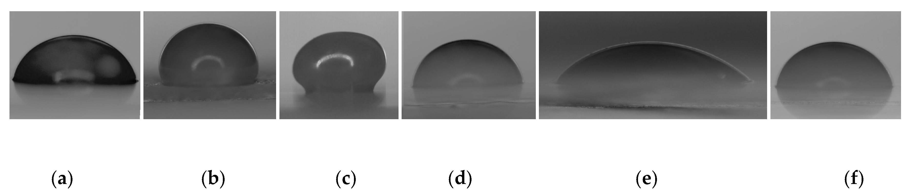
Figure 6.
Wetting behaviour between (a) untreated, (b) mechanical blasted, (c) anodized, (d) phosphated, (e) adhesion promoted, and (f) etched AA6082 and melted PA6.
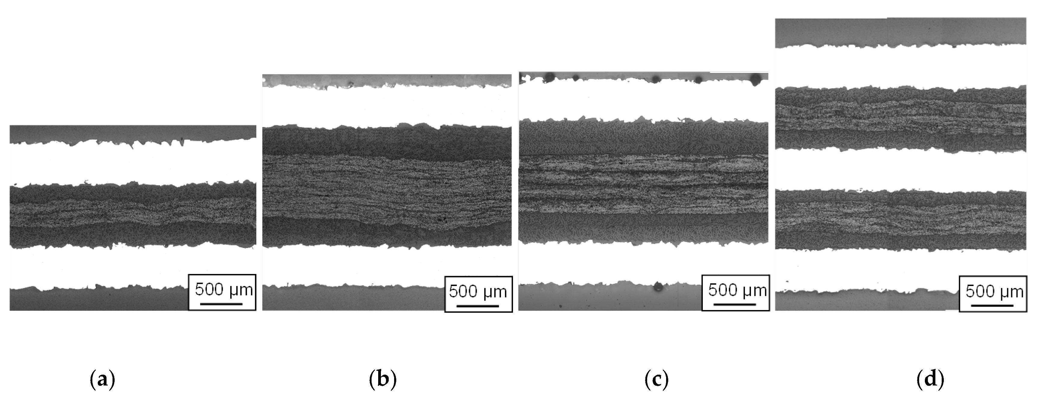
Figure 7.
Cross section of hybrid laminates: (a) 2/1 (GC), (b) 2/1 (GGCC), (c) 2/1 (G′G′CC), and (d) 3/2 (GC).
Figure 8.
3D computed tomography images including cross-sectional images of the fibre distribution of hybrid laminates with mechanically blasted aluminium surface treatment and different layer structures/metal volume content (MVC). 2/1 (GC) with 61% MVC; 2/1 (GGCC) with 44% MVC; 2/1 (G′G′CC) with 44% MVC; 3/2 (GC) with 54% MVC.
Figure 9.
Computed tomography cross-section images showing pore occurrence between the mechanically blasted aluminium surface and the GFR-PA6 layer in hybrid laminates, (a) red plane visualizes displayed cross-section plane; (b) cross-section image for the layer structure/metal volume content (MVC) 2/1 (GC) with 61% and 3/2 (GC) with 54%.
Figure 10.
(a) Stress-displacement curves and (b) stress-strain curves of hybrid laminates with aluminium alloy AA6082-T4 and a graded structure of glass and carbon fibre-reinforced PA6 for different layer structures and metal volume contents.
Figure 11.
Arithmetic tensile strength and strain values of hybrid laminates with aluminium alloy AA6082-T4 and a graded structure of glass and carbon fibre-reinforced PA6 for different layer structures and metal volume contents.
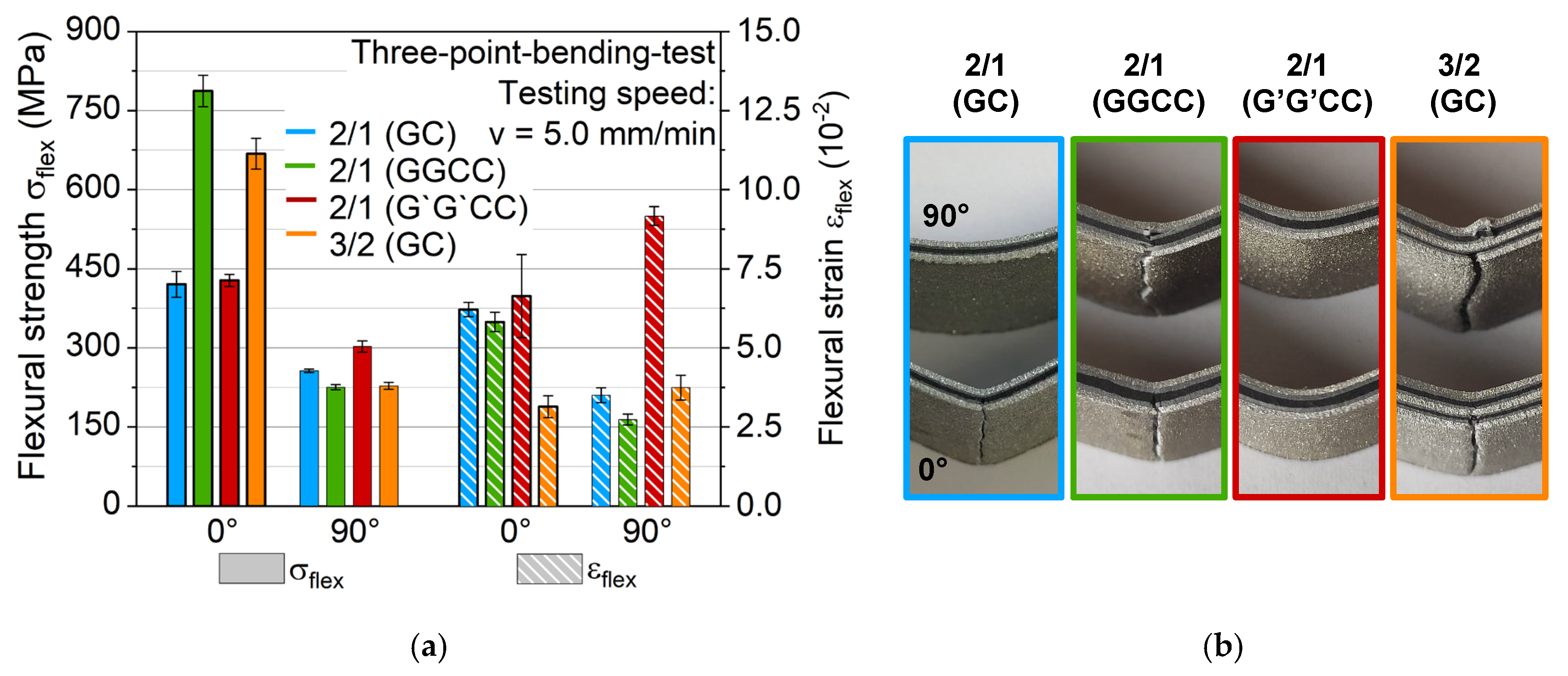
Figure 12.
(a) Arithmetic flexural strength and strain values of hybrid laminates with aluminium alloy AA6082-T4 and a graded structure of glass and carbon fibre-reinforced PA6 for different layer structures and metal volume contents; (b) showing states of failure.
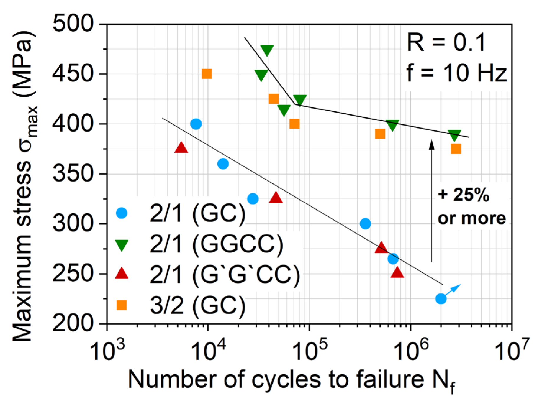
Figure 13.
S-N relationship for hybrid laminates with different layer structures and metal volume contents.
Table 1.
Hybrid laminates of AA6082 and glass/carbon fibre-reinforced polyamide 6 with different layer structures and metal volume contents.
| Short Notation | Composition [Orientation FRP] | Description | Thickness mm | MVC % |
|---|
| 2/1 (GC) | Al/GCCG/Al | | 1.64 | 61 |
| Al/[]/Al |
| 2/1 (GGCC) | Al/GGCCCCGG/Al | | 2.28 | 44 |
| Al/[]/Al |
| 2/1 (G′G′CC) | Al/GGCCCCGG/Al | | 2.28 | 44 |
| Al/[]/Al |
| 3/2 (GC) | Al/GCCG/Al/GCCG/Al | | 2.78 | 54 |
| Al/[]/Al/[]/Al |
| Publisher’s Note: MDPI stays neutral with regard to jurisdictional claims in published maps and institutional affiliations. |
© 2020 by the authors. Licensee MDPI, Basel, Switzerland. This article is an open access article distributed under the terms and conditions of the Creative Commons Attribution (CC BY) license (http://creativecommons.org/licenses/by/4.0/).


