Abstract
Cold forged parts are mainly employed in automotive and aerospace assemblies, and strength plays an essential role in such applications. Backward extrusion is one such process in cold forging for the production of axisymmetrical cup-like parts, which is affected by a number of variables that influence the quality of the products. The study on the influencing parameters becomes necessary as the complexity of the part increases. The present paper focuses on the use of a multi-layered feed forward artificial neural network (ANN) model for determining the effects of process parameters such as billet size, reduction ratio, punch angle, and land height on forming behavior, namely, effective stress, strain, strain rate, and punch force in a cold forging backward extrusion process for AISI 1010 steel. Full factorial design (FFD) has been employed to plan the finite element (FE) simulations and accordingly, the input variables and response patterns are obtained for training from these FE simulations. This ANN model-based analysis reveals that the forming behavior of the cold forging backward extrusion process tends to increase with the billet size as well as the reduction ratios. However, decreases in punch angle and land height lead to the reduction of punch forces, which in turn enhances the punch life. FE simulation along with the developed ANN model scheme would benefit the cold forging industry in minimizing the process development effort in terms of cost and time.
1. Introduction
In the cold forging process, the billet is deformed plastically into the desired shape and confined by the dies with the application of force. There is no scope for flash to occur in closed die cold forging, and hence, the process yields for the manufacture of precise parts. The cold forging process has the advantage of producing near net shape parts for better strength with minimal waste over hot forging [1]. The cold forged parts possess good strength and accuracy; they are principally employed for the automotive and aerospace domain. Cold forging backward extrusion is one such process that has been primarily adopted to produce hollow parts having closed end, cupped parts with holes that are cylindrical, conical, or of other shapes [2].
The cold forging process enables the production of net or near net shape components with very good quality in terms of dimensional accuracy and structural integrity. Complex shape parts such as steering spiders have been produced by the cold forging process with a proper process design and process validation using finite element (FE) simulations [3]. On the contrary, the process calls for higher working forces to deform the billet through the dies and hence leads to higher stress. However, proving the cold forging process design for each particular component for reducing forces is very crucial, and some investigations have been previously carried out with trial and error methods [4].
Liewald et al. [5] performed some studies on the backward cup extrusion cold forging process with an additional controllable tool axis to bring robustness to the process. The cup bottom thickness accuracy was primarily affected by speed differences between the punch and counterpunch, and finally, they concluded that the force-dependent elastic losses could be improved using a controllable additional tool axis. Matsumoto et al. investigated the forming limit and fracture mechanism of magnesium alloy [6] in an upsetting and backward extrusion cold forging process. They suggested that the fracture criterion derived from the viewpoint of strain localization could be effectively applied.
The cold forging process in producing parts for the automotive and aerospace domain has been greatly influenced over the past two decades by advancement in the technology with modern finite element method (FEM) simulation tools. Walters et al. [7] outlined the path of the process simulation developments and implementation in industries to improve the quality of the parts at a reduced process development cost in context with cold heading and heat treatment simulation processes. Modern FE simulation tools are found to be efficient when compared to orthodox methods for part and process developments with reduced development time and cost [8]. The complex cold forging process to the extent of having a floating die could be analyzed with the FE technique, and numerical characterization of the process was achieved [9]. Min and Kim [10] suggested a novel technique for manufacturing a united steering yoke by a precision cold forging process using rigid-plastic FEM to improve the productivity and mechanical properties in a cost-effective way. FE simulation tools have also been utilized to predict the geometrical aspects for forgings. A rigid-thermoplastic FE method was used for simulating the process assuming rigid dies. The strength of the die and work part spring-back analysis was also carried out using the forging simulation results [11]. The process modeling of high-grade aluminum alloy (AA1100) using finite element analysis (FEA) was carried out by Tiernan et al. [12] for cold forging forward extrusion. The factors identified were based on the geometrical attributes such as the reduction ratio, die angle, and land height on the force. The process modeling using FE simulation tools helps with estimating the contribution of influencing factors and understanding the process in a better way.
Researchers have strived enthusiastically to increase the process robustness in cold forging forward extrusion by modeling and optimization to study the deformation behavior of different materials as well as the interactions between the process, tool, and machine in order to improve workpiece accuracy. Novel processes and procedures were also presented in this regard [13,14,15]. The tribological behavior of a cold forging process combining both forward and backward extrusion was investigated for increased part complexity, and the influence of surface integrity, friction factors and lubricants were analyzed as well [16,17,18].
In the recent past, researchers used artificial neural network (ANN) for studying the complex and nonlinear input–output relationships of various processes [19,20,21,22,23]. The work presented by Singh [24] explored the benefits of the ANN approach to model and optimize the process and reported that it could also be possible to forecast agricultural yields using this approach. In the field of manufacturing, De Filippis et al. [25] showed that the ANN approach allows predicting mechanical properties based on the input variables of particular products and thereby benefitting the manufacturing industries by saving development cost and time. The ANN approach is also found to be flexible and efficiently integrated into the functions of process. Some researchers applied ANN models for friction stir welding butt joint to monitor, control, and optimize the process and also to predict the Vickers microhardness and the ultimate tensile strength of aluminum alloy. Casalino et al. [26] analyzed the quality of a laser welding process of an aluminum alloy sheet by implementing codes that were built for ANN models with neural tools (excel ad-in). Karnik and Gaitonde [27] developed ANN models to examine the effect of drilling variables on the burr size of a stainless steel work material. They reported that the nonlinear behavior of the process variables and responses could be reasonably captured using ANN and well depicted with drilling.
The research on a cold forging backward extrusion process is limited in terms of the consideration of induced factors, and hence, the intent of the current study is to explore the important geometrical factors influencing the process and their contribution to the forming behavior. These factors may be related to the configurations of the part, design, and manufacturing of the dies and forming process settings on equipment such as deformation rates, press stiffness, ram velocity, etc. The challenge in the present cold forging industries is to survive in the face of intense competition, especially for small and medium-scale industries, which lack design-simulation resources and most of the time rely upon intuition gained over period of time and experts. In the current research, the ANN model is combined with FE simulation that would help engineers decide upon the geometrical attributes of the punch and billet by following the forming behavior patterns of various combinations. The proposed model and the subsequent analysis gives a competitive edge among cold forging industries by responding quickly to customer inquiries by generating a backward extrusion process plan, which in turn reduces the cost and lead time. Therefore, the existing work is aimed at identifying geometrical attributes and analyzing the forming behavior of a cold forging backward extrusion process using an ANN approach. The forming behavior includes the effective stress, strain, strain rate, and the punch force, and the identified geometrical attributes are the billet size, reduction ratio, punch angle and land height.
2. Experimental Details
2.1. Work Material and Process Variables
The cold forging process imparts strength to the material through the strain-hardening effect, and this process is particularly used in power transmission assemblies. In addition, the process also enables a good control over dimensional accuracy. The work focuses on the cold forging backward extrusion of AISI 1010 steel, which is extensively used in automobile industries, sometimes in carburized and heat-treated conditions [28]. AISI 1010 steel is a low-carbon alloy containing iron as a base with 0.08–0.13% carbon; 0.30–0.60% manganese; phosphorus 0.04% (max); sulfur 0.05% (max); and silicon 0.10% (max). This steel has good deformation characteristics and is ideal for the parts processes through cold working.
Cold forging is a process carried out at room temperature, where a bar stock usually called a billet is deformed into the dies with the application of compressive forces to get the desired shape and size [2,29]. In the cold forging backward extrusion process, the material flows past the punch in the direction opposite and thus producing axisymmetrical cup-like shaped parts, as represented in Figure 1.
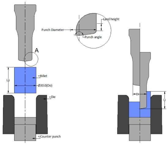
Figure 1.
Cold forging backward extrusion process with punch, die, and billet details.
The factors contributing the cold forging backward extrusion process are numerous, such as configuration of the part, material of the billet and dies, deformation rates, etc. The present work focuses on the important process variables, namely, billet size, reduction ratio, punch angle (a), and land height (h). The billet size ratio (z) is the ratio of the length to diameter of the billet, and in the present study, the diameter is confined to 30 mm due to the practical implications. Only the billet length is adjusted to get the varying ratio levels as per the planning of experiments. The reduction ratio (r) is a ratio of the difference in the cross-sectional area of the billet and punch to the cross-sectional area of the billet, as mentioned by Equations (1) and (2):
2.2. Experimental Design for FE Simulation
The identified process variables and their levels have been devised based on industry practices [30]. Different metals possess different extrusion ratios; the mechanical behavior is the subject matter of physical mechanisms that control formability [31]. The billet size ratio (z) is defined by keeping the diameter of the billet at 30 mm, and the length is adjusted to get the ratios at four levels. Correspondingly, for the reduction ratio, the cross-sectional area of the punch is altered, and the punch sizes are derived as Ø25, Ø23, Ø21, and Ø19 mm with respect to reduction ratios of 0.3, 0.4, 0.5, and 0.6, respectively. Table 1 lists the process variables and their identified levels in the present work of the cold forging backward extrusion process. The extrusion ratio i.e., the extrusion length to extrusion diameter , is restricted to 1.6. This is due to the deformation limitations of the material and is as per practical intuition; otherwise, the cup bottom thickness is maintained with 3 mm. The punch would experience a lot of thrust from the counter punch and may lead to catastrophic failure if the bottom thickness is not maintained, and this is a practical consideration in the cold forging process.

Table 1.
Process variables with their levels.
The FE simulation has been planned based on design of experiments (DOE), and a total of 256 trials have been carried out with full factorial design (FFD) for four factors and each factor identified at four levels [32]. Initially, three-dimensional (3D) models of the punch, billet, and die combinations have been prepared using SOLIDWORKS (Dassault Systems, France) [33] considering the length of extrusion. This length of extrusion dictates the punch and die lengths, which in turn depend on the billet size. Since, the profile is axi-symmetrical, these models are segmented to 30 degrees to reduce the simulation time and space on memory. Appendix A lists the 256 numbers of FE simulation design combinations and the related forming responses.
A 3D segmented assembly model and the FE simulated results obtained through AFDEX (Metal Forming Research Corporation: Republic of Korea) [34] with load versus stroke graph are shown in Figure 2. The forming responses such as effective stress , effective strain , effective strain rate , and punch force (F) from the FE simulations have been recorded.
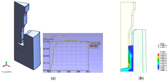
Figure 2.
(a) 3D model assembly of punch, billet, and die; (b) finite element (FE) simulation results with load versus stroke graph.
2.3. Finite Element (FE) Simulation Prerequisites
Three-dimensional model assembly combinations are being done as per the identified process variables, and their levels are designed with an experimental design approach. The input file format for an FE simulation package is stereo-lithographic (stl), and 3D model assembly combinations are being imported to the FE simulation tool accordingly [35]. The FE simulations have been performed with a rigid-plastic assumption model. The next task was to assign the material to the billet. This can be done in to the tool with a built-in material library. FE simulation packages have the facility of different built-in material libraries and friction models, and they need to be chosen for the assembly as per the simulation requirements.
In practice, the billet material is usually coated with a lubrication system (zinc phosphate plus molybdenum disulfide, zinc phosphate plus soap, etc.) and heat treated to enable the deformation of the steel in cold forging [36,37]. Groche et al. [38] determined the friction coefficients in cold forging with six established friction tests of a state-of-the-art industrial tribo-system, and large deviations in between the tests with friction coefficients ranging between 0.02 and 0.07 have been observed. While four of the investigated tests (combined forward rod backward can extrusion, backward can extrusion, upsetting sliding, and sliding compression test) showed the identical friction coefficient of 0.04; two tests (ring compression test with boss and backward can extrusion with simultaneous rotation with friction coefficient value of 0.07 and 0.02, respectively) deviated significantly. Further, in context with backward can extrusion, a maximum of 0.04 friction coefficient value was determined. The authors also modeled the tests individually with the help of FEA with a constant friction coefficient of 0.05 to obtain the tribological loads. Hence, in the present work simulation of the cold forging backward process, the coefficient of friction of 0.05 has been selected (“soap-cold steel” friction model) from the simulation software tool. The travel velocity of the punch is determined as 30 mm/s with the shop floor practice. The punch travel stroke into the billet is restricted as per the extrusion limit.
3. ANN Modeling
3.1. ANN Overview
Artificial neural network (ANN) may be assumed as an interconnected assembly of modest processing constituents or nodes (neurons) [39]. The processing aptitude of ANN is stored in inter unit correlation powers or weights gained from input variables and responses sets usually referred to as training patterns. The capability of solving complicated problems efficiently, in particular problems involving nonlinear behaviors, makes ANN a prominent alternative to the traditional statistical tools. In current research, multi-layer feed forward ANN is applied to study controlling factors on the forming behavior. The architecture of the proposed ANN is demonstrated in Figure 3; it basically consists of neurons divided into an input layer, output layer, and hidden layers.
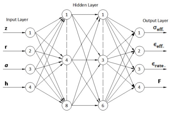
Figure 3.
Multi-layer feed forward artificial neural network architecture.
The neurons between the layers are connected by links having synaptic weights. The error back propagation training algorithm (EBPTA) is created on weight updating to decrease the sum of the squared error for k number of output neurons and is given by Equation (3) as:
where and are the intended output and factual output, respectively, of the neuron for the pattern. The weights of link-connecting neurons are updated built on a negative of gradient of error, which is given by Equation (4) i.e.,
Thus, the weight updating (gradient descent with momentum rule) is done based on Equation (5), which is mentioned below:
where n is the epoch count, is the learning rate, and is the momentum term used to accelerate the convergence of the learning algorithm.
3.2. ANN Training Performance
In this investigation, multi-layered feed forward ANN is applied for developing the intended model. This architecture is used with an error back propagation training algorithm established on gradient descent with momentum and variable learning rate—“traingdx” using the ‘MATLAB NN’ toolbox [40]. The set of input variable and response patterns are obtained from planned FE simulations and are essential input for this supervised learning algorithm. The identified forming responses are obtained through training; this primarily decides the connection weights.
There are four input variables and four output forming responses processed through ANN architecture containing two hidden layers. Among 256 training combinations, 226 sets (88%) were employed for training and 30 sets (12%) have been used for testing. The training parameters of the ANN employed are mentioned in Table 2.

Table 2.
ANN training parameters.
In ANN training, each epoch consists of utilizing 226 training patterns to network, and at the termination of each epoch, the mean square error (MSE) is determined with Equation (6), which is given as:
The training is terminated when the set MSE is attained or a maximum number of epochs is reached. As illustrated in Figure 4, the training was stopped after 2500 epochs and the MSE was found to be below 0.009.
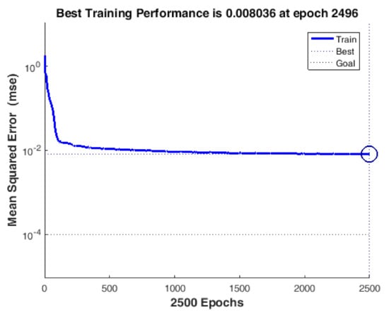
Figure 4.
Variation between mean square error (MSE) and number of epochs of artificial neural network (ANN) training.
3.3. Trained ANN Validation Performance
A trained ANN was primarily tested with 226 patterns of inputs in FFD, which were engaged with training. For every input pattern, the predicted values of the effective stress (), effective strain (), effective strain rate (), and punch force (F) were compared with concerned FE-simulated values, and the absolute % error is calculated with Equation (7), which is given by:
where is the FE simulated value and is the ANN predicted value.
The trained ANN was later tested with the remaining 30 patterns of FFD (not used in training). It is observed that the FE simulated and ANN predicted values are fairly close to each other and the percentage of absolute error for responses is mentioned in Table 3.

Table 3.
Maximum percentage absolute prediction error.
3.4. Regression Plots (Post-Regression Analysis)
The trained network can be demonstrated through linear regression analysis between network responses and equivalent target FE simulated values. Post-regression analysis with 226 pattern sets for the responses is depicted in Figure 5 and the values of coefficient of correlation (R) are found to be 0.9932, 0.9910, 0.9460, and 0.9981 for effective stress () effective strain (), effective strain rate (), and punch force (F), respectively. Similarly, the performance of the trained network is measured with regression analysis of 30 testing pattern sets. The values of co-efficient of correlation (R) as depicted in Figure 6 for the testing pattern sets are observed as 0.9813, 0.9775, 0.9095, and 0.9968 for effective stress (), effective strain (), effective strain rate (), and punch force (F), respectively. Thus, Figure 5 and Figure 6 clearly demonstrate the reliability of the developed ANN models for the identified forming responses.
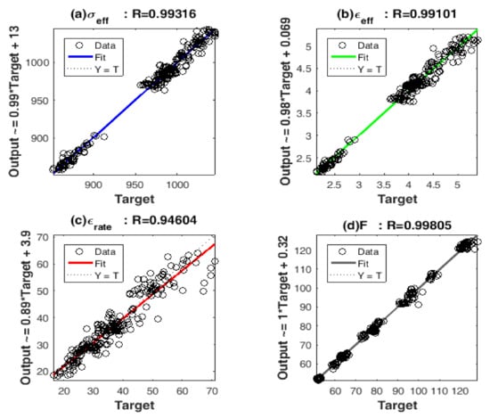
Figure 5.
Post-regression analysis with 226 training patterns for: (a) Effective stress; (b) Effective strain; (c) Effective strain rate; and (d) Punch force.
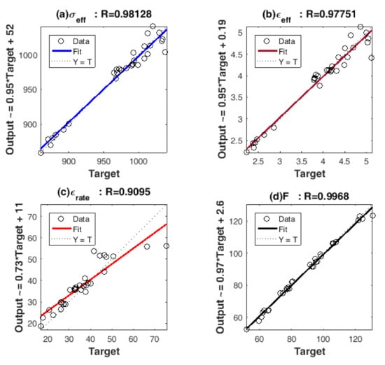
Figure 6.
Post-regression analysis with 30 testing patterns for: (a) Effective stress; (b) Effective strain; (c) Effective strain rate; and (d) Punch force.
4. Results and Discussion
4.1. Analysis of Effective Stress and Strain
The effective stress () and strain () in the billet material with varying billet size ratios (z) for different ranges of reduction ratio (r), punch angle (a), and land height (h) combinations are illustrated in Figure 7 and Figure 8, respectively. As evidenced in Figure 7, for a specified value of the reduction ratio, the effective stress increases sharply with a billet size ratio (z) in the range 0.3–0.6. With a further increase in reduction ratio, the stress also increases. However, with an increased billet size ratio beyond 0.6, the effective stress almost remains constant for the reduction ratios (r) of 0.3 and 0.4. While, for r = 0.5 and r = 0.6, the effective stress continues to rise until the billet size ratio reaches 0.8, and thereafter, there is a marginal increase in the effective stress. For lower reduction ratios of 0.3 and 0.4, the punch diameters are 25 mm and 23 mm, respectively and hence, initially, the larger contact area and stress value increase until the ‘z’ value reaches 0.6; subsequently, the stress remains stable until ‘z’ reaches to 1.2. Beyond a ‘z’ value of 0.6, there is more resistance to deformation for higher reduction ratios of 0.5 and 0.6, which is largely due to the supplementary volume of metal that undergoes deformation between the punch and die that leads to higher stress values. It is apparent from Figure 7 that beyond point ‘C’, a reverse trend is observed for the stress behavior. The similar occurrence is observed for all the identified combinations of punch angle (a) and land height (h) as depicted in Figure 7. However, it is obvious from Figure 7 that the effective stress values are lesser for lower punch angle and land height combinations. The reason might be that a lower punch angle enables the metal flow readily and the shorter land height means reduced friction.
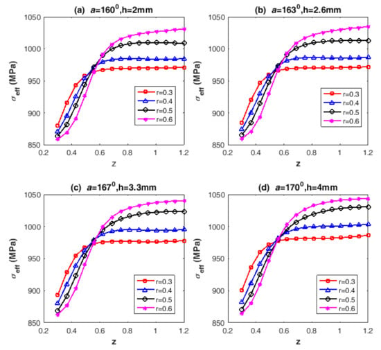
Figure 7.
Effect of billet size ratio on the effective stress in the billet with varying reduction ratios, punch angle (a), and land height (h) at (a) a = 160°, h = 2.0 mm; (b) a = 163°, h = 2.6 mm; (c) a = 167°, h = 3.3 mm; and (d) a = 170°, h = 4.0 mm.
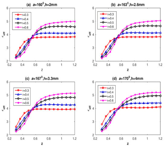
Figure 8.
Effect of billet size ratio on the effective strain in the billet with varying reduction ratios, punch angle (a) and land height (h) at: (a) a = 160°, h = 2.0 mm; (b) a = 163°, h = 2.6 mm; (c) a = 167°, h = 3.3 mm; and (d) a = 170°, h = 4.0 mm.
The effective strain () curves more or less follow the same trend as that of effective stress () curves with varying billet size ratios (z), as demonstrated in Figure 8. The effective strain is predominantly affected by the reduction ratios (r), which is generally because of an increase in the amount of deformation with the reduction ratio.
4.2. Analysis of Effective Strain Rate
The effective strain rate () is a significant parameter, as the strain rate explores the speed at which the deformation proceeds. In the present work, the velocity of the ram in simulation software is set as 30 mm/s based on industry practices.
As noticed from Figure 9, for the reduction ratios of 0.4, 0.5, and 0.6, initially, the effective strain rate () value decreases with the billet size ratio (z) up to 0.5, and thereafter, a steep rise is witnessed until the ‘z’ value reaches 0.8. After that, the strain rate remains virtually constant until ‘z’ approaches 1.2. With the same billet diameter (Ø 30 mm), for the reduction ratios (r) of 0.4, 0.5, and 0.6, the corresponding punch diameters are Ø 23, Ø 21, and Ø 19 mm, respectively, causing the strain rate curve to follow the above trend. Conversely, for the reduction ratio (r) of 0.3, the trend is in the opposed direction, which is mostly due to the fact that the punch contact area is more in case of an ‘r’ of 0.3 (Ø 25 mm punch) that enables an increase in the deformation rate. A similar tendency is also observed for all the identified punch angle (a) and land height (h) combinations, but the effective strain rate is smaller for smaller punch angle and land height combinations.
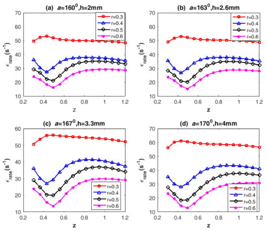
Figure 9.
Effect of billet size ratio on the effective strain rate with varying reduction ratios, punch angle (a), and land height (h) at (a) a = 160°, h = 2.0 mm; (b) a = 163°, h = 2.6 mm; (c) a = 167°, h = 3.3 mm; and (d) a = 170°, h = 4.0 mm.
4.3. Analysis of Punch Force
The consequence of billet size ratio (z) in the cold forging backward extrusion process on the punch force (F) is exhibited in Figure 10. It is noticed that the primarily punch force (F) increases gradually with the billet size ratio (z) in the range 0.3–0.6 for a given reduction ratio (r). From then on, there is no substantial effect of billet size ratio on punch force for the specified reduction ratio. A similar trend is observed for different reduction ratio, punch angle (a) and land height (h) combinations. It is apparent from Figure 10 that the influence of reduction ratio (r) on punch force is a dominating factor. This is obvious, because the punch diameter varies from 25 to 19 mm for the reduction ratios from 0.3 to 0.6, for a fixed billet diameter of 30 mm. This is because the deformation amount, i.e., the mean strain increases with the reduction ratio. It is revealed from Figure 10 that the billet length has a modest influence on the punch force, as the billet diameter is fixed to 30 mm and the length is varied to obtain the ratio from 0.6 to 1.2 in the present investigation of the cold forging backward extrusion process.
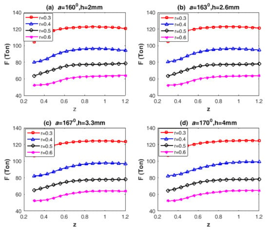
Figure 10.
Effect of billet size ratio on the punch force with varying reduction ratios, punch angle (a), and land height (h) at (a) a = 160°, h = 2.0 mm; (b) a = 163°, h = 2.6 mm; (c) a = 167°, h = 3.3 mm; (d) a = 170°, h = 4.0 mm.
Although Figure 10 indicates a marginal effect of punch angle (a) and land height (h) combinations on the punch force, the punch geometry directly influences the material flow, and therefore, for lower combinations of ‘a’ and ‘h’, the punch forces are lower when compared to higher combinations. A higher punch angle enhances the metal volume that experiences shear deformation and hence an increased punch force. On the other hand, a smaller land height decreases the punch friction that minimizes the punch force for a specified reduction ratio.
4.4. Analysis of Interaction Effects on Forming Behavior
The forming behavior models developed through ANN are also exercised to examine the interaction effects of two factors by constructing 3D surface plots by keeping the other two factors at higher levels. 3D surface plots were created using the ‘MATLAB NN’ toolbox [40]. A surface analysis of two-factor interaction effects gives considerable information on the forming behavior with regard to selected process parameters.
4.4.1. Interaction Effect of Billet Size and Reduction Ratio
The interaction effect due to the billet size and reduction ratio on the forming behavior is illustrated in Figure 11. As witnessed in Figure 11a, b, for any reduction ratio, both the effective stress and strain increase linearly with the billet size ratio. However, little variations are observed at smaller billet size ratios of 0.3 and 0.6 when compared to higher billet size ratios of 0.9 and 1.2. It is also noticed that the behavior of stress as well as strain is more impulsive with a billet size ratio in the range 0.3–0.6, which is thereafter observed to be faltering. On the whole, for a fixed billet diameter, the variation in billet length is practically not influencing the stress and strain values when compared to punch diameters.
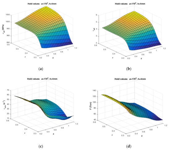
Figure 11.
Interaction effect of billet size and reduction ratio on forming behavior: (a) effective stress; (b) effective strain; (c) effective strain rate; (d) punch force.
As exhibited in Figure 11c, the strain rate nonlinearly decreases with the reduction ratio for any specified billet size ratio; conversely, for any particular reduction ratio, not much variation is evidenced with the billet size ratio. The strain rate is more sensitive than the billet size ratio for higher reduction ratios compared to lower reduction ratios. The punch force is found to be more sensitive to reduction ratio than the billet size ratio, as revealed in Figure 11d. For a given billet size ratio, the forces tend to decrease with the reduction ratio. Moreover, for a given reduction ratio, the punch force increases with the billet size ratio until it reaches 0.6, and later, the force approximately remains stable. By and large, we can deduce that even though the punch forces are insensitive to billet length, nevertheless, they are majorly affected by punch diameters for fixed billet diameters.
4.4.2. Interaction Effect of Billet Size Ratio and Punch Angle
The effective stress and strain values are more sensitive to billet size ratio than punch angle, as evident in Figure 12a, b. Although the effective stress and strain marginally increase with punch angle for a given billet size ratio, they are less susceptible to variations in punch angle. This is due to the fact that a smaller punch angle facilitates metal deformation readily and hence leads to a decrease in stress values.
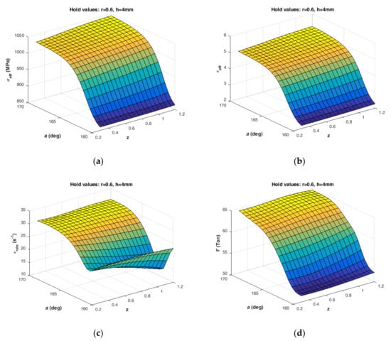
Figure 12.
Interaction effect of billet size ratio and punch angle on forming behavior: (a) effective stress; (b) effective strain; (c) effective strain rate; and (d) punch force.
As depicted in Figure 12c, for a given punch angle, the strain rate increases with the billet size ratio; however, the strain rate values are observed to be minimal for a punch angle of 165 degrees for all the specified billet size ratios. The surface plot also reveals that the strain rates are more sensitive for higher punch angles, i.e., the higher the punch angle, the larger the shear deformation area, and hence the larger the deformation rate. Figure 12d depicts the variation of punch force with billet size ratio for different punch angle values. It is observed that for a given punch angle, the force increases nonlinearly with billet size ratio until it reaches 0.6, and beyond, it roughly remains constant. In normal industry practices, an effort is always made to reduce the punch forces with a smaller punch angle by aiding metal deformation, while the billet size is always dictated by part configuration and hence difficult to alter. Moreover, the punch angle is decided not only by the strength, production quantity, and life of the punch but it also lies with the internal cup configuration of the component.
4.4.3. Interaction Effect of Billet Size Ratio and Land Height
The interaction effect of billet size ratio and land height is presented in Figure 13. Effective stress and strain values (Figure 13a,b) are insensitive to land height for any given billet size ratio; however, for a specified reduction ratio, an increased trend is observed for stress and strain behavior with billet size ratio. Consequently, effective strain rate values are more sensitive to the variations of billet size ratio than land height; furthermore, for a given land height, the strain rate values are increasing with the billet size ratio, as depicted in Figure 13c. Even though the land height does not have much of an influence on the strain rate, it does affect the punch life, mainly because a larger land height means more contact area and friction.
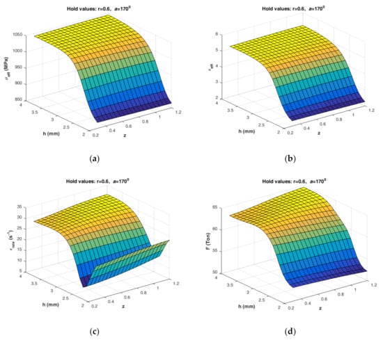
Figure 13.
Interaction effect of billet size ratio and land height on forming behavior: (a) effective stress; (b) effective strain; (c) effective strain rate; and (d) punch force.
The punch force is also not very sensitive to land height for a given billet size ratio, as evidenced from Figure 13d. The punch force is one such practical issue in the cold forging industry, and an effort is always made to reduce the deformation force by articulating the punch angle and land height. However, usually, there is a trade-off between the production quantity and the life of the punch. Hence, the present work would help the cold forging industry expand the process knowledge base on backward extrusion and shall help minimize the process development effort in terms of cost and time by utilizing the developed ANN-based models.
5. Conclusions
The present work emphasizes exploring the influence of process variables such as billet size (z), reduction ratio (r), punch angle (a), and land height (h) on the forming behavior of a cold forging backward extrusion process of AISI 1010 steel. The study is intended to ascertain the avenues for process modeling using ANN. The following are concluded based on ANN modeling for the present investigations of cold forging backward extrusion.
- The reduction ratio is the important factor influencing the forming behavior for the billet size ratio in the range 0.3–0.6. This is apparent, because the effective stress and strain increase with the reduction ratio. On the contrary, the reverse trend is observed for the strain rate and punch force. This is due to the fact that as the punch diameter increases for the same billet size, the effective stress as well as strain tend to increase; contrary to this, the strain rate and punch force tend to decrease.
- Beyond a billet size ratio of 0.6, only a marginal effect on the forming behavior is noticed. The probable reason might be that even if an increased billet length expands the billet volume, the deformation area remains constant for any specified reduction ratio.
- The billet length has little cause on the punch force; however, the punch force increases with a decrease in reduction ratio, which is principally due to the increased strain with an increase in reduction ratio.
- The punch angle and land height directly affect the forming behavior. As lower combinations of punch angle and land height influence the material flow, all the identified process parameters, namely, effective stress, strain, strain rate, and punch force, tend to decrease. By and large, the punch angle and land height are the decisive factors, keeping in mind the production quantity and punch life.
- The proposed ANN model based on FE simulations not only assesses the forming behavior with respect to the identified process variables but also assists in understanding the process design of the backward extrusion process of AISI 1010 steel.
In the present competitive era, the current research attempted would help the cold forging industry to expand the process knowledge base on the backward extrusion process and shall help minimize the process development effort in terms of cost and time.
Author Contributions
FE Simulation, P.M.P.; methodology, P.M.P., V.N.G. and J.P.D.; software, S.R.K., V.N.G. and P.M.P.; validation, V.N.G., P.M.P. and J.P.D.; formal analysis, P.M.P., V.N.G. and V.N.K.; investigation, P.M.P., V.N.G. and T.K.G.R.; resources, T.K.G.R. and S.R.K.; writing—original draft preparation—P.M.P., V.N.K. and V.N.G.; writing—review and editing, J.P.D. and S.R.K.; supervision, V.N.G. and V.N.K.; project administration, V.N.G., S.R.K. and V.N.K.; All authors have read and agreed to the published version of the manuscript.
Funding
This research received no external funding.
Acknowledgments
The authors would like express special thanks to KLE Technological University for the sanction of capacity building funds (CBF) to carry out the project. Entire work has been carried out under the CBF for the year 2020-21.
Conflicts of Interest
The authors declare no conflict of interest.
Appendix A

Table A1.
FE simulation design combinations and the forming responses.
Table A1.
FE simulation design combinations and the forming responses.
| Test No. | Input Variables | Forming Aspects | ||||||
|---|---|---|---|---|---|---|---|---|
| z | r | a (deg) | h mm | σeff. (MPa) | ϵeff. | ϵrate. (s−1) | F (Ton) | |
| 1 | 0.3 | 0.3 | 160 | 2.0 | 881.0 | 2.505 | 47.95 | 104.80 |
| 2 | 0.3 | 0.3 | 160 | 2.6 | 877.8 | 2.456 | 50.84 | 105.10 |
| 3 | 0.3 | 0.3 | 160 | 3.3 | 880.9 | 2.468 | 46.34 | 105.70 |
| 4 | 0.3 | 0.3 | 160 | 4.0 | 888.6 | 2.571 | 49.35 | 107.20 |
| 5 | 0.3 | 0.3 | 163 | 2.0 | 882.8 | 2.525 | 49.48 | 105.70 |
| 6 | 0.3 | 0.3 | 163 | 2.6 | 882.3 | 2.510 | 45.98 | 105.50 |
| 7 | 0.3 | 0.3 | 163 | 3.3 | 887.8 | 2.583 | 52.95 | 105.70 |
| 8 | 0.3 | 0.3 | 163 | 4.0 | 892.9 | 2.654 | 51.35 | 109.30 |
| 9 | 0.3 | 0.3 | 167 | 2.0 | 891.6 | 2.617 | 55.76 | 105.80 |
| 10 | 0.3 | 0.3 | 167 | 2.6 | 892.5 | 2.622 | 47.43 | 105.90 |
| 11 | 0.3 | 0.3 | 167 | 3.3 | 896.0 | 2.686 | 50.24 | 106.40 |
| 12 | 0.3 | 0.3 | 167 | 4.0 | 892.0 | 2.608 | 52.90 | 108.70 |
| 13 | 0.3 | 0.3 | 170 | 2.0 | 913.1 | 2.902 | 65.20 | 105.80 |
| 14 | 0.3 | 0.3 | 170 | 2.6 | 901.3 | 2.773 | 60.46 | 106.20 |
| 15 | 0.3 | 0.3 | 170 | 3.3 | 902.9 | 2.800 | 57.91 | 106.50 |
| 16 | 0.3 | 0.3 | 170 | 4.0 | 899.6 | 2.847 | 75.63 | 107.80 |
| 17 | 0.3 | 0.4 | 160 | 2.0 | 869.0 | 2.319 | 36.28 | 79.26 |
| 18 | 0.3 | 0.4 | 160 | 2.6 | 868.5 | 2.320 | 36.08 | 79.20 |
| 19 | 0.3 | 0.4 | 160 | 3.3 | 863.3 | 2.264 | 31.49 | 79.20 |
| 20 | 0.3 | 0.4 | 160 | 4.0 | 870.4 | 2.375 | 38.13 | 80.69 |
| 21 | 0.3 | 0.4 | 163 | 2.0 | 876.9 | 2.425 | 35.93 | 79.55 |
| 22 | 0.3 | 0.4 | 163 | 2.6 | 873.8 | 2.376 | 33.53 | 80.57 |
| 23 | 0.3 | 0.4 | 163 | 3.3 | 876.3 | 2.409 | 38.33 | 80.93 |
| 24 | 0.3 | 0.4 | 163 | 4.0 | 864.6 | 2.298 | 39.29 | 80.71 |
| 25 | 0.3 | 0.4 | 167 | 2.0 | 869.6 | 2.329 | 30.55 | 79.94 |
| 26 | 0.3 | 0.4 | 167 | 2.6 | 872.6 | 2.370 | 36.08 | 80.31 |
| 27 | 0.3 | 0.4 | 167 | 3.3 | 876.7 | 2.413 | 32.87 | 80.32 |
| 28 | 0.3 | 0.4 | 167 | 4.0 | 878.4 | 2.458 | 36.92 | 80.69 |
| 29 | 0.3 | 0.4 | 170 | 2.0 | 888.8 | 2.567 | 37.40 | 80.99 |
| 30 | 0.3 | 0.4 | 170 | 2.6 | 882.3 | 2.494 | 33.70 | 82.13 |
| 31 | 0.3 | 0.4 | 170 | 3.3 | 882.6 | 2.504 | 38.12 | 81.26 |
| 32 | 0.3 | 0.4 | 170 | 4.0 | 888.7 | 2.570 | 36.38 | 83.16 |
| 33 | 0.3 | 0.5 | 160 | 2.0 | 862.2 | 2.255 | 28.86 | 63.13 |
| 34 | 0.3 | 0.5 | 160 | 2.6 | 864.2 | 2.267 | 30.48 | 63.31 |
| 35 | 0.3 | 0.5 | 160 | 3.3 | 861.5 | 2.255 | 29.67 | 63.42 |
| 36 | 0.3 | 0.5 | 160 | 4.0 | 867.1 | 2.315 | 30.74 | 64.17 |
| 37 | 0.3 | 0.5 | 163 | 2.0 | 862.9 | 2.256 | 30.35 | 64.33 |
| 38 | 0.3 | 0.5 | 163 | 2.6 | 865.3 | 2.278 | 29.07 | 64.36 |
| 39 | 0.3 | 0.5 | 163 | 3.3 | 864.6 | 2.288 | 28.95 | 64.06 |
| 40 | 0.3 | 0.5 | 163 | 4.0 | 876.4 | 2.436 | 30.00 | 64.54 |
| 41 | 0.3 | 0.5 | 167 | 2.0 | 866.7 | 2.301 | 24.54 | 64.79 |
| 42 | 0.3 | 0.5 | 167 | 2.6 | 874.2 | 2.382 | 22.69 | 65.00 |
| 43 | 0.3 | 0.5 | 167 | 3.3 | 867.8 | 2.310 | 28.88 | 65.25 |
| 44 | 0.3 | 0.5 | 167 | 4.0 | 873.4 | 2.384 | 28.38 | 65.85 |
| 45 | 0.3 | 0.5 | 170 | 2.0 | 876.4 | 2.430 | 31.78 | 65.77 |
| 46 | 0.3 | 0.5 | 170 | 2.6 | 873.3 | 2.373 | 24.77 | 65.29 |
| 47 | 0.3 | 0.5 | 170 | 3.3 | 875.6 | 2.400 | 25.35 | 65.78 |
| 48 | 0.3 | 0.5 | 170 | 4.0 | 876.4 | 2.413 | 24.26 | 66.49 |
| 49 | 0.3 | 0.6 | 160 | 2.0 | 858.0 | 2.193 | 23.30 | 51.06 |
| 50 | 0.3 | 0.6 | 160 | 2.6 | 851.8 | 2.125 | 22.45 | 51.30 |
| 51 | 0.3 | 0.6 | 160 | 3.3 | 862.4 | 2.243 | 24.39 | 51.51 |
| 52 | 0.3 | 0.6 | 160 | 4.0 | 852.0 | 2.133 | 22.57 | 51.67 |
| 53 | 0.3 | 0.6 | 163 | 2.0 | 864.6 | 2.270 | 24.25 | 51.90 |
| 54 | 0.3 | 0.6 | 163 | 2.6 | 859.8 | 2.215 | 22.61 | 51.79 |
| 55 | 0.3 | 0.6 | 163 | 3.3 | 859.7 | 2.211 | 23.40 | 51.79 |
| 56 | 0.3 | 0.6 | 163 | 4.0 | 859.7 | 2.215 | 22.46 | 52.04 |
| 57 | 0.3 | 0.6 | 167 | 2.0 | 864.8 | 2.272 | 21.50 | 52.44 |
| 58 | 0.3 | 0.6 | 167 | 2.6 | 867.2 | 2.297 | 24.49 | 52.63 |
| 59 | 0.3 | 0.6 | 167 | 3.3 | 859.7 | 2.244 | 22.19 | 52.53 |
| 60 | 0.3 | 0.6 | 167 | 4.0 | 861.9 | 2.261 | 24.99 | 52.52 |
| 61 | 0.3 | 0.6 | 170 | 2.0 | 864.6 | 2.268 | 22.22 | 52.96 |
| 62 | 0.3 | 0.6 | 170 | 2.6 | 862.0 | 2.253 | 26.07 | 53.15 |
| 63 | 0.3 | 0.6 | 170 | 3.3 | 860.2 | 2.220 | 23.76 | 52.81 |
| 64 | 0.3 | 0.6 | 170 | 4.0 | 871.9 | 2.357 | 23.22 | 53.21 |
| 65 | 0.6 | 0.3 | 160 | 2.0 | 977.0 | 4.028 | 49.62 | 118.90 |
| 66 | 0.6 | 0.3 | 160 | 2.6 | 967.7 | 3.912 | 50.56 | 121.70 |
| 67 | 0.6 | 0.3 | 160 | 3.3 | 973.1 | 3.901 | 57.06 | 120.00 |
| 68 | 0.6 | 0.3 | 160 | 4.0 | 984.8 | 4.088 | 53.33 | 119.80 |
| 69 | 0.6 | 0.3 | 163 | 2.0 | 972.1 | 3.869 | 50.70 | 119.70 |
| 70 | 0.6 | 0.3 | 163 | 2.6 | 965.6 | 3.795 | 50.04 | 123.30 |
| 71 | 0.6 | 0.3 | 163 | 3.3 | 973.7 | 3.899 | 67.55 | 122.20 |
| 72 | 0.6 | 0.3 | 163 | 4.0 | 973.1 | 3.830 | 69.74 | 119.60 |
| 73 | 0.6 | 0.3 | 167 | 2.0 | 969.0 | 3.822 | 51.98 | 119.70 |
| 74 | 0.6 | 0.3 | 167 | 2.6 | 973.2 | 3.845 | 55.18 | 122.10 |
| 75 | 0.6 | 0.3 | 167 | 3.3 | 974.7 | 3.906 | 52.89 | 120.90 |
| 76 | 0.6 | 0.3 | 167 | 4.0 | 964.9 | 3.805 | 66.32 | 124.40 |
| 77 | 0.6 | 0.3 | 170 | 2.0 | 980.9 | 3.980 | 61.98 | 120.60 |
| 78 | 0.6 | 0.3 | 170 | 2.6 | 977.4 | 3.955 | 55.22 | 123.10 |
| 79 | 0.6 | 0.3 | 170 | 3.3 | 978.9 | 4.059 | 70.91 | 119.50 |
| 80 | 0.6 | 0.3 | 170 | 4.0 | 987.9 | 4.121 | 56.30 | 119.90 |
| 81 | 0.6 | 0.4 | 160 | 2.0 | 989.2 | 4.162 | 31.69 | 90.58 |
| 82 | 0.6 | 0.4 | 160 | 2.6 | 975.2 | 3.867 | 33.13 | 91.47 |
| 83 | 0.6 | 0.4 | 160 | 3.3 | 978.3 | 3.923 | 38.70 | 92.08 |
| 84 | 0.6 | 0.4 | 160 | 4.0 | 980.5 | 3.964 | 38.84 | 91.71 |
| 85 | 0.6 | 0.4 | 163 | 2.0 | 973.6 | 3.930 | 39.47 | 92.39 |
| 86 | 0.6 | 0.4 | 163 | 2.6 | 986.1 | 4.065 | 42.55 | 93.75 |
| 87 | 0.6 | 0.4 | 163 | 3.3 | 982.1 | 4.054 | 36.84 | 93.92 |
| 88 | 0.6 | 0.4 | 163 | 4.0 | 972.0 | 3.827 | 39.03 | 92.82 |
| 89 | 0.6 | 0.4 | 167 | 2.0 | 983.4 | 4.026 | 36.88 | 92.89 |
| 90 | 0.6 | 0.4 | 167 | 2.6 | 985.0 | 4.105 | 27.66 | 90.89 |
| 91 | 0.6 | 0.4 | 167 | 3.3 | 990.8 | 4.280 | 33.70 | 92.28 |
| 92 | 0.6 | 0.4 | 167 | 4.0 | 980.5 | 4.014 | 33.46 | 92.85 |
| 93 | 0.6 | 0.4 | 170 | 2.0 | 987.1 | 4.149 | 35.55 | 94.58 |
| 94 | 0.6 | 0.4 | 170 | 2.6 | 984.5 | 4.116 | 46.42 | 93.19 |
| 95 | 0.6 | 0.4 | 170 | 3.3 | 993.8 | 4.206 | 40.23 | 93.45 |
| 96 | 0.6 | 0.4 | 170 | 4.0 | 998.0 | 4.344 | 32.69 | 99.80 |
| 97 | 0.6 | 0.5 | 160 | 2.0 | 981.9 | 4.023 | 26.57 | 72.34 |
| 98 | 0.6 | 0.5 | 160 | 2.6 | 991.2 | 4.179 | 29.55 | 73.97 |
| 99 | 0.6 | 0.5 | 160 | 3.3 | 977.4 | 3.943 | 38.58 | 72.72 |
| 100 | 0.6 | 0.5 | 160 | 4.0 | 981.6 | 4.015 | 35.55 | 72.40 |
| 101 | 0.6 | 0.5 | 163 | 2.0 | 999.5 | 4.307 | 26.36 | 72.95 |
| 102 | 0.6 | 0.5 | 163 | 2.6 | 983.8 | 4.029 | 25.79 | 73.63 |
| 103 | 0.6 | 0.5 | 163 | 3.3 | 982.0 | 4.042 | 26.88 | 73.08 |
| 104 | 0.6 | 0.5 | 163 | 4.0 | 984.2 | 4.024 | 28.50 | 73.34 |
| 105 | 0.6 | 0.5 | 167 | 2.0 | 981.9 | 4.007 | 25.48 | 73.75 |
| 106 | 0.6 | 0.5 | 167 | 2.6 | 992.7 | 4.190 | 25.71 | 73.70 |
| 107 | 0.6 | 0.5 | 167 | 3.3 | 989.7 | 4.135 | 34.32 | 74.21 |
| 108 | 0.6 | 0.5 | 167 | 4.0 | 985.3 | 4.088 | 23.18 | 74.05 |
| 109 | 0.6 | 0.5 | 170 | 2.0 | 997.4 | 4.271 | 23.26 | 73.68 |
| 110 | 0.6 | 0.5 | 170 | 2.6 | 1011.0 | 4.536 | 30.81 | 73.76 |
| 111 | 0.6 | 0.5 | 170 | 3.3 | 1008.0 | 4.490 | 20.66 | 74.50 |
| 112 | 0.6 | 0.5 | 170 | 4.0 | 989.3 | 4.176 | 22.23 | 74.44 |
| 113 | 0.6 | 0.6 | 160 | 2.0 | 992.3 | 4.176 | 20.13 | 58.37 |
| 114 | 0.6 | 0.6 | 160 | 2.6 | 984.8 | 4.118 | 21.23 | 59.19 |
| 115 | 0.6 | 0.6 | 160 | 3.3 | 978.1 | 3.946 | 21.84 | 58.88 |
| 116 | 0.6 | 0.6 | 160 | 4.0 | 972.8 | 3.834 | 21.35 | 59.29 |
| 117 | 0.6 | 0.6 | 163 | 2.0 | 999.5 | 4.452 | 18.60 | 59.92 |
| 118 | 0.6 | 0.6 | 163 | 2.6 | 997.9 | 4.411 | 20.04 | 59.15 |
| 119 | 0.6 | 0.6 | 163 | 3.3 | 997.6 | 4.270 | 23.14 | 59.72 |
| 120 | 0.6 | 0.6 | 163 | 4.0 | 982.8 | 4.080 | 17.86 | 59.70 |
| 121 | 0.6 | 0.6 | 167 | 2.0 | 984.1 | 4.105 | 16.46 | 60.40 |
| 122 | 0.6 | 0.6 | 167 | 2.6 | 995.7 | 4.240 | 18.97 | 60.43 |
| 123 | 0.6 | 0.6 | 167 | 3.3 | 992.9 | 4.234 | 18.79 | 60.66 |
| 124 | 0.6 | 0.6 | 167 | 4.0 | 995.4 | 4.254 | 23.21 | 60.52 |
| 125 | 0.6 | 0.6 | 170 | 2.0 | 999.7 | 4.349 | 18.02 | 61.62 |
| 126 | 0.6 | 0.6 | 170 | 2.6 | 999.2 | 4.393 | 21.27 | 61.28 |
| 127 | 0.6 | 0.6 | 170 | 3.3 | 1013.0 | 4.563 | 16.73 | 61.21 |
| 128 | 0.6 | 0.6 | 170 | 4.0 | 998.0 | 4.306 | 22.06 | 60.60 |
| 129 | 0.9 | 0.3 | 160 | 2.0 | 969.5 | 3.816 | 49.13 | 123.10 |
| 130 | 0.9 | 0.3 | 160 | 2.6 | 959.4 | 3.680 | 67.08 | 121.60 |
| 131 | 0.9 | 0.3 | 160 | 3.3 | 981.0 | 3.984 | 60.22 | 121.10 |
| 132 | 0.9 | 0.3 | 160 | 4.0 | 973.1 | 3.827 | 46.59 | 121.60 |
| 133 | 0.9 | 0.3 | 163 | 2.0 | 977.3 | 3.902 | 48.46 | 120.00 |
| 134 | 0.9 | 0.3 | 163 | 2.6 | 965.1 | 3.723 | 44.03 | 122.30 |
| 135 | 0.9 | 0.3 | 163 | 3.3 | 969.9 | 3.861 | 44.98 | 122.60 |
| 136 | 0.9 | 0.3 | 163 | 4.0 | 985.1 | 4.040 | 47.33 | 123.20 |
| 137 | 0.9 | 0.3 | 167 | 2.0 | 980.7 | 3.965 | 54.43 | 125.00 |
| 138 | 0.9 | 0.3 | 167 | 2.6 | 969.1 | 3.779 | 41.71 | 130.50 |
| 139 | 0.9 | 0.3 | 167 | 3.3 | 975.5 | 3.923 | 45.21 | 122.80 |
| 140 | 0.9 | 0.3 | 167 | 4.0 | 974.8 | 3.865 | 46.96 | 125.00 |
| 141 | 0.9 | 0.3 | 170 | 2.0 | 982.4 | 4.097 | 64.72 | 125.60 |
| 142 | 0.9 | 0.3 | 170 | 2.6 | 988.3 | 4.219 | 61.68 | 126.50 |
| 143 | 0.9 | 0.3 | 170 | 3.3 | 981.6 | 4.019 | 60.07 | 122.20 |
| 144 | 0.9 | 0.3 | 170 | 4.0 | 985.9 | 4.095 | 69.63 | 122.80 |
| 145 | 0.9 | 0.4 | 160 | 2.0 | 994.8 | 4.264 | 37.18 | 95.68 |
| 146 | 0.9 | 0.4 | 160 | 2.6 | 975.8 | 3.958 | 36.47 | 95.57 |
| 147 | 0.9 | 0.4 | 160 | 3.3 | 982.8 | 4.002 | 41.65 | 95.48 |
| 148 | 0.9 | 0.4 | 160 | 4.0 | 981.7 | 3.980 | 36.56 | 96.02 |
| 149 | 0.9 | 0.4 | 163 | 2.0 | 992.1 | 4.187 | 36.84 | 94.64 |
| 150 | 0.9 | 0.4 | 163 | 2.6 | 992.9 | 4.248 | 45.63 | 94.87 |
| 151 | 0.9 | 0.4 | 163 | 3.3 | 984.6 | 4.089 | 36.11 | 95.78 |
| 152 | 0.9 | 0.4 | 163 | 4.0 | 992.6 | 4.199 | 35.25 | 96.77 |
| 153 | 0.9 | 0.4 | 167 | 2.0 | 989.9 | 4.194 | 37.80 | 95.55 |
| 154 | 0.9 | 0.4 | 167 | 2.6 | 996.3 | 4.268 | 41.48 | 96.95 |
| 155 | 0.9 | 0.4 | 167 | 3.3 | 987.9 | 4.086 | 36.15 | 95.97 |
| 156 | 0.9 | 0.4 | 167 | 4.0 | 979.5 | 4.094 | 42.97 | 96.95 |
| 157 | 0.9 | 0.4 | 170 | 2.0 | 1016.0 | 4.634 | 43.51 | 97.55 |
| 158 | 0.9 | 0.4 | 170 | 2.6 | 1001.0 | 4.429 | 47.78 | 98.01 |
| 159 | 0.9 | 0.4 | 170 | 3.3 | 992.5 | 4.350 | 46.38 | 98.40 |
| 160 | 0.9 | 0.4 | 170 | 4.0 | 1006.0 | 4.580 | 43.46 | 102.00 |
| 161 | 0.9 | 0.5 | 160 | 2.0 | 1006.0 | 4.514 | 38.86 | 77.24 |
| 162 | 0.9 | 0.5 | 160 | 2.6 | 1003.0 | 4.577 | 40.39 | 76.80 |
| 163 | 0.9 | 0.5 | 160 | 3.3 | 1007.0 | 4.456 | 33.68 | 76.45 |
| 164 | 0.9 | 0.5 | 160 | 4.0 | 1003.0 | 4.412 | 39.43 | 79.75 |
| 165 | 0.9 | 0.5 | 163 | 2.0 | 1008.0 | 4.503 | 37.61 | 77.41 |
| 166 | 0.9 | 0.5 | 163 | 2.6 | 1030.0 | 5.005 | 33.09 | 78.05 |
| 167 | 0.9 | 0.5 | 163 | 3.3 | 1006.0 | 4.466 | 38.13 | 77.31 |
| 168 | 0.9 | 0.5 | 163 | 4.0 | 1019.0 | 4.709 | 42.11 | 77.24 |
| 169 | 0.9 | 0.5 | 167 | 2.0 | 1021.0 | 4.844 | 35.30 | 77.71 |
| 170 | 0.9 | 0.5 | 167 | 2.6 | 1013.0 | 4.610 | 34.71 | 78.40 |
| 171 | 0.9 | 0.5 | 167 | 3.3 | 1017.0 | 4.727 | 36.97 | 78.30 |
| 172 | 0.9 | 0.5 | 167 | 4.0 | 1033.0 | 5.029 | 35.02 | 76.85 |
| 173 | 0.9 | 0.5 | 170 | 2.0 | 1039.0 | 5.270 | 37.43 | 77.85 |
| 174 | 0.9 | 0.5 | 170 | 2.6 | 1026.0 | 4.880 | 37.10 | 77.90 |
| 175 | 0.9 | 0.5 | 170 | 3.3 | 1020.0 | 4.747 | 32.58 | 77.61 |
| 176 | 0.9 | 0.5 | 170 | 4.0 | 1029.0 | 4.927 | 32.60 | 78.90 |
| 177 | 0.9 | 0.6 | 160 | 2.0 | 1025.0 | 4.921 | 27.59 | 62.75 |
| 178 | 0.9 | 0.6 | 160 | 2.6 | 1022.0 | 4.772 | 26.27 | 62.85 |
| 179 | 0.9 | 0.6 | 160 | 3.3 | 1034.0 | 5.037 | 26.55 | 62.07 |
| 180 | 0.9 | 0.6 | 160 | 4.0 | 1032.0 | 5.062 | 32.54 | 63.24 |
| 181 | 0.9 | 0.6 | 163 | 2.0 | 1033.0 | 5.033 | 27.10 | 62.50 |
| 182 | 0.9 | 0.6 | 163 | 2.6 | 1029.0 | 5.035 | 30.64 | 62.62 |
| 183 | 0.9 | 0.6 | 163 | 3.3 | 1026.0 | 4.948 | 29.41 | 62.16 |
| 184 | 0.9 | 0.6 | 163 | 4.0 | 1026.0 | 4.958 | 28.13 | 63.58 |
| 185 | 0.9 | 0.6 | 167 | 2.0 | 1044.0 | 5.224 | 26.88 | 62.40 |
| 186 | 0.9 | 0.6 | 167 | 2.6 | 1045.0 | 5.323 | 26.07 | 63.85 |
| 187 | 0.9 | 0.6 | 167 | 3.3 | 1027.0 | 4.867 | 31.55 | 63.01 |
| 188 | 0.9 | 0.6 | 167 | 4.0 | 1030.0 | 4.997 | 26.21 | 63.09 |
| 189 | 0.9 | 0.6 | 170 | 2.0 | 1045.0 | 5.309 | 25.80 | 62.97 |
| 190 | 0.9 | 0.6 | 170 | 2.6 | 1045.0 | 5.394 | 26.27 | 62.84 |
| 191 | 0.9 | 0.6 | 170 | 3.3 | 1043.0 | 5.336 | 34.62 | 63.36 |
| 192 | 0.9 | 0.6 | 170 | 4.0 | 1045.0 | 5.365 | 31.82 | 62.93 |
| 193 | 1.2 | 0.3 | 160 | 2.0 | 961.5 | 3.634 | 53.43 | 120.80 |
| 194 | 1.2 | 0.3 | 160 | 2.6 | 960.9 | 3.620 | 45.71 | 122.70 |
| 195 | 1.2 | 0.3 | 160 | 3.3 | 956.6 | 3.630 | 43.45 | 126.80 |
| 196 | 1.2 | 0.3 | 160 | 4.0 | 969.0 | 3.810 | 42.30 | 118.80 |
| 197 | 1.2 | 0.3 | 163 | 2.0 | 965.3 | 3.760 | 42.41 | 121.60 |
| 198 | 1.2 | 0.3 | 163 | 2.6 | 964.6 | 3.774 | 51.76 | 121.80 |
| 199 | 1.2 | 0.3 | 163 | 3.3 | 965.8 | 3.717 | 49.06 | 121.80 |
| 200 | 1.2 | 0.3 | 163 | 4.0 | 961.9 | 3.685 | 50.58 | 121.10 |
| 201 | 1.2 | 0.3 | 167 | 2.0 | 968.4 | 3.800 | 44.39 | 122.50 |
| 202 | 1.2 | 0.3 | 167 | 2.6 | 966.7 | 3.817 | 57.36 | 121.60 |
| 203 | 1.2 | 0.3 | 167 | 3.3 | 986.8 | 4.071 | 49.23 | 121.70 |
| 204 | 1.2 | 0.3 | 167 | 4.0 | 973.3 | 3.829 | 50.40 | 123.40 |
| 205 | 1.2 | 0.3 | 170 | 2.0 | 982.7 | 4.073 | 53.37 | 123.10 |
| 206 | 1.2 | 0.3 | 170 | 2.6 | 996.8 | 4.368 | 53.68 | 124.50 |
| 207 | 1.2 | 0.3 | 170 | 3.3 | 988.1 | 4.121 | 60.40 | 124.30 |
| 208 | 1.2 | 0.3 | 170 | 4.0 | 978.2 | 4.114 | 49.35 | 128.10 |
| 209 | 1.2 | 0.4 | 160 | 2.0 | 989.8 | 4.168 | 30.42 | 95.38 |
| 210 | 1.2 | 0.4 | 160 | 2.6 | 978.4 | 4.007 | 33.74 | 94.77 |
| 211 | 1.2 | 0.4 | 160 | 3.3 | 982.9 | 4.044 | 36.65 | 97.00 |
| 212 | 1.2 | 0.4 | 160 | 4.0 | 978.5 | 4.002 | 35.31 | 95.33 |
| 213 | 1.2 | 0.4 | 163 | 2.0 | 984.7 | 4.164 | 31.78 | 97.71 |
| 214 | 1.2 | 0.4 | 163 | 2.6 | 991.8 | 4.302 | 35.93 | 97.04 |
| 215 | 1.2 | 0.4 | 163 | 3.3 | 990.3 | 4.133 | 32.44 | 96.11 |
| 216 | 1.2 | 0.4 | 163 | 4.0 | 1007.0 | 4.487 | 31.40 | 94.56 |
| 217 | 1.2 | 0.4 | 167 | 2.0 | 999.7 | 4.339 | 33.53 | 96.57 |
| 218 | 1.2 | 0.4 | 167 | 2.6 | 986.1 | 4.122 | 36.12 | 95.92 |
| 219 | 1.2 | 0.4 | 167 | 3.3 | 1011.0 | 4.542 | 39.95 | 98.08 |
| 220 | 1.2 | 0.4 | 167 | 4.0 | 979.8 | 4.070 | 51.81 | 95.64 |
| 221 | 1.2 | 0.4 | 170 | 2.0 | 1006.0 | 4.431 | 45.04 | 96.85 |
| 222 | 1.2 | 0.4 | 170 | 2.6 | 1014.0 | 4.613 | 34.93 | 96.10 |
| 223 | 1.2 | 0.4 | 170 | 3.3 | 1002.0 | 4.399 | 43.03 | 98.07 |
| 224 | 1.2 | 0.4 | 170 | 4.0 | 1038.0 | 5.117 | 37.39 | 97.99 |
| 225 | 1.2 | 0.5 | 160 | 2.0 | 1014.0 | 4.601 | 34.25 | 77.82 |
| 226 | 1.2 | 0.5 | 160 | 2.6 | 1008.0 | 4.495 | 34.26 | 77.97 |
| 227 | 1.2 | 0.5 | 160 | 3.3 | 1002.0 | 4.381 | 31.81 | 77.98 |
| 228 | 1.2 | 0.5 | 160 | 4.0 | 1014.0 | 4.607 | 34.98 | 76.88 |
| 229 | 1.2 | 0.5 | 163 | 2.0 | 1010.0 | 4.690 | 29.50 | 77.79 |
| 230 | 1.2 | 0.5 | 163 | 2.6 | 1005.0 | 4.460 | 30.89 | 78.17 |
| 231 | 1.2 | 0.5 | 163 | 3.3 | 1026.0 | 4.896 | 34.24 | 78.05 |
| 232 | 1.2 | 0.5 | 163 | 4.0 | 1017.0 | 4.692 | 32.84 | 78.01 |
| 233 | 1.2 | 0.5 | 167 | 2.0 | 1019.0 | 4.728 | 32.59 | 79.21 |
| 234 | 1.2 | 0.5 | 167 | 2.6 | 1030.0 | 5.088 | 27.83 | 77.75 |
| 235 | 1.2 | 0.5 | 167 | 3.3 | 1013.0 | 4.590 | 32.93 | 79.37 |
| 236 | 1.2 | 0.5 | 167 | 4.0 | 1031.0 | 5.108 | 38.86 | 79.29 |
| 237 | 1.2 | 0.5 | 170 | 2.0 | 1024.0 | 4.855 | 28.72 | 79.29 |
| 238 | 1.2 | 0.5 | 170 | 2.6 | 1023.0 | 4.831 | 38.64 | 78.90 |
| 239 | 1.2 | 0.5 | 170 | 3.3 | 1013.0 | 4.639 | 35.49 | 78.52 |
| 240 | 1.2 | 0.5 | 170 | 4.0 | 1029.0 | 4.958 | 35.71 | 79.34 |
| 241 | 1.2 | 0.6 | 160 | 2.0 | 1030.0 | 4.983 | 30.17 | 62.56 |
| 242 | 1.2 | 0.6 | 160 | 2.6 | 1035.0 | 5.047 | 28.52 | 62.94 |
| 243 | 1.2 | 0.6 | 160 | 3.3 | 1008.0 | 4.497 | 28.55 | 62.52 |
| 244 | 1.2 | 0.6 | 160 | 4.0 | 1023.0 | 4.887 | 26.93 | 62.83 |
| 245 | 1.2 | 0.6 | 163 | 2.0 | 1035.0 | 5.077 | 28.53 | 63.05 |
| 246 | 1.2 | 0.6 | 163 | 2.6 | 1034.0 | 5.067 | 29.34 | 62.23 |
| 247 | 1.2 | 0.6 | 163 | 3.3 | 1023.0 | 4.931 | 27.42 | 64.16 |
| 248 | 1.2 | 0.6 | 163 | 4.0 | 1025.0 | 4.896 | 34.06 | 64.98 |
| 249 | 1.2 | 0.6 | 167 | 2.0 | 1039.0 | 5.158 | 25.52 | 64.94 |
| 250 | 1.2 | 0.6 | 167 | 2.6 | 1038.0 | 5.115 | 31.06 | 63.74 |
| 251 | 1.2 | 0.6 | 167 | 3.3 | 1020.0 | 4.859 | 27.56 | 65.37 |
| 252 | 1.2 | 0.6 | 167 | 4.0 | 1038.0 | 5.142 | 30.67 | 64.51 |
| 253 | 1.2 | 0.6 | 170 | 2.0 | 1024.0 | 4.947 | 30.85 | 63.11 |
| 254 | 1.2 | 0.6 | 170 | 2.6 | 1033.0 | 5.033 | 25.10 | 63.88 |
| 255 | 1.2 | 0.6 | 170 | 3.3 | 1039.0 | 5.202 | 26.31 | 65.40 |
| 256 | 1.2 | 0.6 | 170 | 4.0 | 1036.0 | 5.094 | 31.30 | 63.76 |
References
- Handbook, M. American Society for Metals. In Forming and Forging; ASM International: Novelty, OH, USA, 1996; Volume 14, pp. 1376–1400. [Google Scholar]
- Taylan, A.; Gracious, N.; Gangshu, S. Cold and hot forging fundamentals and application. In ASM Metals Handbook; ASM International: Novelty, OH, USA, 2005; pp. 337–338. [Google Scholar]
- Meidert, M.; Hänsel, M. Net shape cold forging to close tolerances under QS 9000 aspects. J. Mater. Process. Technol. 2000, 98, 150–154. [Google Scholar] [CrossRef]
- Politis, D.J.; Politis, N.J.; Lin, J.; Dean, T.A. A review of force reduction methods in precision forging axisymmetric shapes. Int. J. Adv. Manuf. Technol. 2018, 97, 2809–2833. [Google Scholar] [CrossRef]
- Liewald, M.; Schiemann, T.; Mletzko, C. Automatically Controlled (Cold-) Forging Processes. Procedia CIRP 2014, 18, 39–44. [Google Scholar] [CrossRef]
- Matsumoto, R.; Kubo, T.; Osakada, K. Fracture of magnesium alloy in cold forging. CIRP Ann. 2007, 56, 293–296. [Google Scholar] [CrossRef]
- Walters, J.; Wu, W.T.; Arvind, A.; Li, G.; Lambert, D.; Tang, J. Recent development of process simulation for industrial applications. J. Mater. Process. Technol. 2000, 98, 205–211. [Google Scholar] [CrossRef]
- Vincze, G.; Butuc, M.C.; Barlat, F.; Rauch, E.F.; Grácio, J.J. Experimental analysis and simulation of metals subjected to strain path changes. In Proceedings of the 7th Brazilian Congress on Manufacturing Engineering 2013, Penedo, Brazil, 20–24 May 2013. [Google Scholar]
- Ryu, C.H.; Joun, M.S. Finite element simulation of the cold forging process having a floating die. J. Mater. Process. Technol. 2001, 112, 121–126. [Google Scholar] [CrossRef]
- Min, D.K.; Kim, M.E. A study on precision cold forging process improvements for the steering yoke of automobiles by the rigid–plastic finite-element method. J. Mater. Process. Technol. 2003, 138, 339–342. [Google Scholar] [CrossRef]
- Jun, B.Y.; Kang, S.M.; Lee, M.C.; Park, R.H.; Joun, M.S. Prediction of geometric dimensions for cold forgings using the finite element method. J. Mater. Process. Technol. 2007, 189, 459–465. [Google Scholar] [CrossRef]
- Tiernan, P.; Hillery, M.T.; Draganescu, B.; Gheorghe, M. Modelling of cold extrusion with experimental verification. J. Mater. Process. Technol. 2005, 168, 360–366. [Google Scholar] [CrossRef]
- Kroiß, T.; Engel, U.; Merklein, M. Comprehensive approach for process modeling and optimization in cold forging considering interactions between process, tool and press. J. Mater. Process. Technol. 2013, 213, 1118–1127. [Google Scholar] [CrossRef]
- Hu, C.; Zhao, Z.; Gong, A.; Shi, W. Study of an alternative novel cold forging process. Mater. Manuf. Process. 2015, 30, 1210–1217. [Google Scholar] [CrossRef]
- Hild, R.; Bergs, T.; Mattfeld, P.; Trauth, D.; Klocke, F.; Hoffmann, D.C.; Kruppe, N.C.; Brögelmann, T.; Bobzin, K. Analysis of wear phenomena during forward extrusion under dry friction conditions. Wear 2019, 426, 1362–1370. [Google Scholar] [CrossRef]
- Hu, C.; Yin, Q.; Zhao, Z. A novel method for determining friction in cold forging of complex parts using a steady combined forward and backward extrusion test. J. Mater. Process. Technol. 2017, 249, 57–66. [Google Scholar] [CrossRef]
- Sagisaka, Y.; Ishibashi, I.; Nakamura, T.; Sekizawa, M.; Sumioka, Y.; Kawano, M. Evaluation of environmentally friendly lubricants for cold forging. J. Mater. Process. Technol. 2012, 212, 1869–1874. [Google Scholar] [CrossRef]
- Andreas, K.; Merklein, M. Influence of surface integrity on the tribological performance of cold forging tools. Proc. CIRP 2014, 13, 61–66. [Google Scholar] [CrossRef][Green Version]
- Karnik, S.R.; Gaitonde, V.N.; Davim, J.P. A comparative study of the ANN and RSM modeling approaches for predicting burr size in drilling. Int. J. Adv. Manuf. Technol. 2008, 38, 868–883. [Google Scholar] [CrossRef]
- Karnik, S.R.; Gaitonde, V.N.; Mata, F.; Davim, J.P. Investigative study on machinability aspects of unreinforced and reinforced PEEK composite machining using ANN model. J. Reinf. Plast. Compos. 2008, 27, 751–768. [Google Scholar] [CrossRef]
- Gaitonde, V.N.; Karnik, S.R.; Davim, J.P. Study on the influence of MQL and cutting conditions on machinability of brass using Artificial Neural Network. Int. J. Mater. Prod. Technol. 2010, 37, 155–172. [Google Scholar] [CrossRef]
- Gaitonde, V.N.; Shashikant, A.L.; Karnik, S.R.; Deshpande, A.S. Analysis and optimization of hole quality parameters in cenosphere-multiwall carbon nanotube hybrid composites drilling using artificial neural network and gravitational search technique. In Drilling Technology: Fundamentals and Recent Advances; Paulo Davim, J., Ed.; De Gruyter Series; De Gruyter Oldenbourg: Berlin, Germany, 2018; Chapter 6; pp. 161–188. [Google Scholar]
- Karnik, S.R.; Gaitonde, V.N.; Rubio, J.C.; Correia, A.E.; Abrão, A.M.; Davim, J.P. Delamination analysis in high speed drilling of carbon fiber reinforced plastics (CFRP) using artificial neural network model. Mater. Des. 2008, 29, 1768–1776. [Google Scholar] [CrossRef]
- Singh, R.K. Artificial neural network methodology for modelling and forecasting maize crop yield. Agric. Econ. Res. Rev. 2008, 21, 5–10. [Google Scholar]
- De Filippis, L.A.; Serio, L.M.; Facchini, F.; Mummolo, G. ANN Modelling to Optimize Manufacturing Process. In Advanced Applications for Artificial Neural Networks; IntechOpen: London, UK, 2017. [Google Scholar]
- Casalino, G.; Facchini, F.; Mortello, M.; Mummolo, G. ANN modelling to optimize manufacturing processes: The case of laser welding. IFAC-PapersOnLine 2016, 49, 378–383. [Google Scholar] [CrossRef]
- Karnik, S.R.; Gaitonde, V.N. Development of artificial neural network models to study the effect of process parameters on burr size in drilling. Int. J. Adv. Manuf. Technol. 2008, 39, 439–453. [Google Scholar] [CrossRef]
- Lv, Z.; Qian, L.; Liu, S.; Zhan, L.; Qin, S. Preparation and mechanical behavior of ultra-high strength low-carbon steel. Materials 2020, 13, 459. [Google Scholar] [CrossRef]
- Ku, T.W.; Kim, L.H.; Kang, B.S. Multi-stage cold forging and experimental investigation for the outer race of constant velocity joints. Mater. Des. 2013, 49, 368–385. [Google Scholar] [CrossRef]
- Abdullah, A.B.; Samad, Z. Cold forging die design: Recent advanced and future trends. J. Appl. Sci. 2007, 7, 868–876. [Google Scholar]
- Vincze, G.T. Investigation Methodologies for Metals Used in Forming Processes. Ph.D. Thesis, Universidade de Aveiro, Agueda, Portugal, 2007. [Google Scholar]
- Montgomery, D.C. Design and Analysis of Experiments; John Wiley & Sons. Inc.: New York, NY, USA, 1997; pp. 200–201. [Google Scholar]
- Planchard, D. SOLIDWORKS 2018 Tutorial with Video Instruction; SDC Publications: Mission, KS, USA, 2018. [Google Scholar]
- Joun, M. Recent Advances in Metal Forming Simulation Technology for Automobile Parts by AFDEX. IOP Conf. Ser. Mater. Sci. Eng. 2020, 834, 012016. [Google Scholar] [CrossRef]
- Hsia, S.Y.; Shih, P.Y. Wear improvement of tools in the cold forging process for long hex flange nuts. Materials 2015, 8, 6640–6657. [Google Scholar] [CrossRef]
- Groche, P.; Zang, S.; Kramer, P.; Müller, C.; Rezanov, V. Influence of a heat treatment prior to cold forging operations on the performance of lubricants. Tribol. Int. 2015, 92, 67–71. [Google Scholar] [CrossRef]
- Gariety, M.; Ngaile, G.; Altan, T. Evaluation of new cold forging lubricants without zinc phosphate precoat. Int. J. Mach. Tool Manufact. 2007, 47, 673–681. [Google Scholar] [CrossRef]
- Groche, P.; Kramer, P.; Bay, N.; Christiansen, P.; Dubar, L.; Hayakawa, K.; Hu, C.; Kitamura, K.; Moreau, P. Friction coefficients in cold forging: A global perspective. CIRP Ann. 2018, 67, 261–264. [Google Scholar] [CrossRef]
- Schalkoff, R.B. Artificial Neural Networks; McGraw-Hill: Singapore, 1997. [Google Scholar]
- MATLAB NN Toolbox; Math Works Incorporation: Natick, MA, USA, 2016.
Publisher’s Note: MDPI stays neutral with regard to jurisdictional claims in published maps and institutional affiliations. |
© 2020 by the authors. Licensee MDPI, Basel, Switzerland. This article is an open access article distributed under the terms and conditions of the Creative Commons Attribution (CC BY) license (http://creativecommons.org/licenses/by/4.0/).