Article

First-Principles Study on the Promoting Effect of Unsaturated Bonds in PTFE on Triboelectrification During Contact with Al

1
Southern Marine Science and Engineering Guangdong Laboratory Zhuhai, School of Ocean Engineering and Technology, Sun Yat-sen University, Zhuhai 519082, China
2
Hanjiang National Laboratory, Wuhan 430060, China
3
Guangdong Provincial Key Laboratory of Information Technology for Deep Water Acoustics, Zhuhai 519082, China
4
Department of Mechanical and Electrical Engineering, Ocean University of China, Qingdao 266100, China
*
Authors to whom correspondence should be addressed.
Lubricants 2026, 14(8), 291; https://doi.org/10.3390/lubricants14080291
Submission received: 23 June 2026 / Revised: 21 July 2026 / Accepted: 27 July 2026 / Published: 29 July 2026
(This article belongs to the Special Issue Fundamentals and Applications of Triboelectrification)

Abstract

Contact electrification (CE), also referred to as triboelectrification, describes electron transfer occurring at the interface of dissimilar materials. Its microscopic mechanism remains unclarified due to the complex coupling of multiple physical fields, yet the rapid development of triboelectric nanogenerators (TENGs) has rendered CE a prominent research hotspot in tribology on account of its promising application prospects. Metal/polymer combinations have been widely employed for CE research due to their significant differences in electron gain and loss. Nevertheless, most existing studies focus solely on saturated polymers, and systematic comparative analyses between saturated and unsaturated molecular structures are rarely reported. Accordingly, the intrinsic microscopic origin of enhanced interfacial electrification performance induced by unsaturated groups has not been fully understood. In this work, first-principles calculations based on density functional theory (DFT) are implemented to establish interfacial models consisting of an Al substrate and three types of PTFE single chains: fully saturated-PTFE, PTFE with unsaturated bonds at the chain terminus, and PTFE with unsaturated bonds in the middle of the chain. The inherent mechanism governing the modulation of CE behaviors by unsaturated structures are comprehensively revealed from multiple perspectives, including charge transfer, electrostatic potential, and frontier orbital distribution. Computational results demonstrate that unsaturated groups drastically elevate local electrostatic potential and strengthen the electron-trapping capability of molecular chains, thereby substantially boosting CE performance. Moreover, this modulation effect exhibits remarkable position dependence, where unsaturated structures located in the middle of molecular chains deliver better performance improvement than terminal unsaturated moieties. The electron-donating and electron-accepting properties of materials are dominated by the energy level characteristics of the highest occupied molecular orbital (HOMO) and the lowest unoccupied molecular orbital (LUMO), respectively. This study elucidates the microscopic mechanism of CE at unsaturated polymer/metal interfaces at the molecular scale, and provides theoretical support for optimizing the output performance of TENGs through surface modification strategies.

1. Introduction

Contact electrification (CE), a physical phenomenon discovered over 2600 years ago, has long been targeted for suppression owing to its adverse effects [1]. Nevertheless, the invention of triboelectric nanogenerators (TENGs) effectively integrates CE with electrostatic induction, revealing enormous potential for energy harvesting [2,3,4,5,6,7] and driving CE toward positive functional applications [8,9] as a vibrant research frontier. Although existing studies have verified that charge transfer dominates the CE process [10,11,12], the fundamental mechanism underlying charge transfer remains elusive, as this phenomenon involves intricate non-equilibrium [13] and multiscale effects [14,15]. This lack of theoretical foundation leaves the two mainstream optimization strategies—surface micro/nanostructure and polymer interfacial modification—without quantitative theoretical support, thereby hindering the rational design of high-efficiency triboelectric layers [16,17,18].
To elucidate the microscopic mechanisms of CE and refine the relevant theoretical framework, the academic community has conducted extensive research. Early explanations based on material electronegativity and the triboelectric series have now been revised: electronegativity is not the primary driving force of charge transfer, and the triboelectric series serves only as a rough empirical guide with no quantitative predictive capability [12]. The current consensus holds that CE is a synergistic process involving multiple mechanisms, including electron tunneling, ion migration, and the breaking of mechanical chemical bonds [19]. Building on these insights, the academic community has gradually established a comprehensive theoretical framework in recent years: the Šutka team demonstrated that intermolecular forces and interfacial adhesion differences explain CE between identical materials [20]; Verners et al. confirmed that charge transfer between dielectric polymers is primarily driven by mass transfer [21]; and Mizzi, Marks, and others developed theories of flexoelectricity and band-ratchet transport, providing a unified explanation for classic challenges, such as electrification between materials of the same type and pressure-induced polarity reversal [22,23,24]. Furthermore, Fatti et al. delineated the applicability ranges of different first-principles models [19], while Olson and Marks constructed a unified analytical framework for triboelectricity [25].
Since metals possess a free electron gas structure, they can serve as reference electrodes for analyzing the intrinsic interfacial behavior of polymers; the metal–polymer pairing system has thus become a classic model for investigating the microscopic mechanisms of CE. Based on this classical model, current experimental and first-principles simulation studies on CE have primarily focused on saturated polymer systems. Experimentally, researchers have demonstrated using contact-separated TENGs that charge transfer behavior is jointly determined by the surface state density and the energy gap between occupied electronic levels [26]. By introducing functional groups such as -F and -OH onto the polymer surface, studies have clarified the mechanisms governing charge transfer at the solid–liquid interface [27] and established an electron cloud overlap model to explain the underlying physics [9]. Theoretical simulations indicate that electron transfer from metal to polymer exhibits a unidirectional, localized distribution [15], with the lowest unoccupied molecular orbitals (LUMO) of the polymer acting as the electron acceptor [8]. Halogen groups such as C-F and C-Cl can influence the efficiency of interfacial charge transfer by modulating orbital energy levels and electron residence time [28]. Furthermore, external electric fields regulate electron transfer by altering the interfacial potential difference, with reverse fields capable of suppressing or entirely eliminating CE [29].
Compared to the extensive research on saturated systems, research on polymers containing unsaturated bonds is currently largely limited to macroscopic experiments. For example, it has been demonstrated that radiation-induced bond damage can enhance the electron-donating ability of polyimides [30], and that unsaturated groups introduced via magnetron sputtering can significantly boost the CE performance of PTFE films at solid–solid and solid–liquid interfaces [9]. Regarding fluoropolymer friction layer materials commonly used in TENGs, studies have confirmed that PTFE’s excellent negative triboelectric properties stem from the electron-trapping effect of oxidation and unsaturated defects generated during friction [31]. Although these findings offer important insights into the interface modification of fluoropolymers, current research still has several limitations. Specifically, existing studies fail to distinguish the distinct roles of unsaturated defects at different structural sites, lack a quantitative comparison between saturated and unsaturated PTFE interfaces, and leave the intrinsic orbital-scale mechanisms of unsaturated charge-trapping sites elusive.
In summary, to address this gap, first-principles calculations based on density functional theory (DFT) are performed in this work. Three types of PTFE single chains, namely saturated-PTFE, unsaturated-head-PTFE with unsaturated bonds at the chain terminal, and unsaturated-middle-PTFE with unsaturated bonds in the middle of the chain, are selected as research objects, and their interfacial adsorption configurations with aluminum (Al) substrates are constructed separately. By establishing interfacial models at the monomeric, single-chain, and amorphous scales, we thoroughly dissect the underlying microscopic mechanisms across charge transfer dynamics, structural effects, and orbital characteristics. The calculations reveal that unsaturated groups serve as the critical structural motifs for boosting CE performance. These unsaturated groups generate strong electron affinity by drastically elevating local electrostatic potential, and rearrange the distribution of the highest occupied molecular orbitals (HOMO and LUMO) to strengthen the electron-capturing capacity of the entire molecular chain. Furthermore, such a modulation effect exhibits position-dependent behavior, where unsaturated-middle-PTFE delivers superior performance compared with unsaturated-head-PTFE. The electron-donating and electron-accepting properties of materials are dominated by the energy level characteristics of the HOMO and LUMO, respectively. This work provides precise microscopic theoretical insights for improving the output performance of TENGs via surface chemical modification strategies.

2. Model and Computational Details

Based on first-principles calculations, this study investigates the CE at the interfaces between Al and three types of amorphous PTFE, including saturated-PTFE, unsaturated-head-PTFE and unsaturated-middle-PTFE. Firstly, single-chain polymer models were constructed, and amorphous cells were established via the atom-based summation and Ewald method. Annealing and molecular dynamics (MD) simulations were then conducted to achieve structural relaxation and obtain stable configurations. Subsequently, the optimized polymer surfaces were combined with Al slabs to construct complete Al/polymer interfacial systems. Finally, using the CASTEP module within the DFT framework [32,33,34,35,36,37,38], interfacial electron transfer behaviors were systematically calculated and analyzed.

2.1. Single-Chain Molecular Models

In this study, 3D polymer structural models were constructed and preprocessed using the Materials Visualizer module in Materials Studio 2020 software package. PTFE was selected as the model material due to its uniform backbone structure, which enables the isolated investigation of carbon–carbon unsaturated bonds under controlled single-variable conditions. Additionally, the well-established research system of PTFE facilitates the mechanistic analysis and comparative study of research findings. To build the models, an isotactic saturated-PTFE single chain comprising seven repeating units was first constructed based on tetrafluoroethylene units with defined head and tail atoms [39]. A chain length of seven repeating units effectively isolates chain-end boundary interferences, thereby enabling precise distinction between the charge transfer behaviors of unsaturated bonds located at chain terminals and those within the backbone. Since C=C unsaturated double bonds can locate either at the chain end (–CF=CF2) or within the chain interior (–CF=CF–) [9], two modified models were developed based on the saturated-PTFE single chain by introducing a C=C double bond at the chain end and within the chain backbone, respectively. These are designated as the unsaturated-head-PTFE single chain (with an unsaturated bond at the chain end) and the unsaturated-middle-PTFE single chain (with an unsaturated bond within the chain backbone). Existing experimental studies have confirmed that magnetron sputtering can selectively introduce these two types of unsaturated defects into PTFE films [9], thereby validating the experimental relevance of our simulation models.
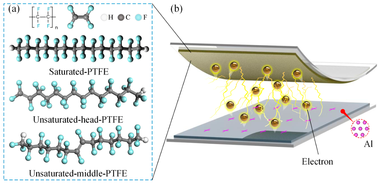
Subsequently, geometric optimization of the above three types of PTFE single chains was implemented using the Dmol3 module. During the optimization calculations, the generalized gradient approximation of the Perdew–Burke–Ernzerhof (GGA-PBE) functional was adopted, and the double numerical plus polarization (DNP) basis set was selected. The convergence thresholds of total energy, force and displacement were set to 1 × 10⁻⁵ Ha, 2 × 10⁻³ Ha/Å and 5 × 10⁻³ Å, respectively. The structurally optimized single-chain configurations are displayed in Figure 1a. Meanwhile, the density of states (DOS), partial density of states (PDOS), electrostatic potential, and orbital energy level distribution were synchronously calculated to analyze the electron accumulation and dissipation zones of the prepared polymer materials [28,40].

2.2. Amorphous Polymer Unit Cell Models

Subsequently, the geometry-optimized single chains were utilized to construct cell models using the amorphous cell module. To balance computational efficiency and structural rationality, each model was constructed with five molecular chains at predefined initial densities [15]. Five molecular chains are sufficient to cover the metal contact interface. Adding more chains only increases the bulk thickness without influencing the charge transfer behavior at the interface. Furthermore, the model is optimized via energy annealing to reduce random configurational artifacts. The Condensed-phase Optimized Molecular Potentials for Atomistic Simulation Studies (COMPASS) force field was selected for all simulations, as it can accurately predict the molecular structures, conformations, vibrational features, and thermodynamic properties of both isolated and condensed-phase systems. Regarding the summation algorithms, the atom-based method and Ewald method were used to calculate van der Waals and Coulomb interactions, respectively [41,42], and the cutoff distance for all polymer systems was specified as 12.5 Å.
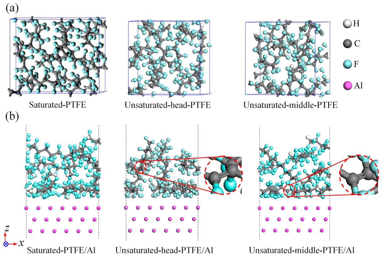
Next, structural relaxation of the constructed amorphous cells was performed using the Forcite module. The annealing procedure was conducted over a temperature range of 300–800 K, followed by a 1000 ps MD simulation under the NVT (constant number of particles, volume, and temperature) ensemble. After full relaxation, the simulated densities of saturated-PTFE, unsaturated-head-PTFE, and unsaturated-middle-PTFE were 2.11, 2.21, and 2.19 g/cm3, respectively. These numerical results are in good agreement with previously reported experimental measurements and simulation data [43], confirming the validity of the adopted simulation parameters and system dimensions. The relaxed structures of the three amorphous polymer models are illustrated in Figure 2a.

2.3. Modeling of the Al/Amorphous–Polymers Contact Interface

Al possesses a face-centered cubic crystal structure, with the (111) plane serving as its most thermodynamically stable, close-packed surface. Accordingly, the Al (111) surface was selected as the metallic substrate [39]. The relaxed amorphous polymer cells were combined with the optimized Al (111) slab to construct Al/polymer contact configurations. Periodic boundary conditions were applied along the X and Y directions, while a 12 Å vacuum layer was added along the Z-axis to eliminate artificial interactions induced by periodic images. The composite interfacial models were further geometrically optimized using the Forcite module based on the COMPASS force field to reach the minimum-energy state [44]. Van der Waals and Coulombic interactions were calculated using atom-based summation and Ewald summation methods, respectively [41,42]. The lattice parameters a and b of all interfacial systems were both 17.18 Å, and the fully optimized contact structures are displayed in Figure 2b.

2.4. First-Principles Simulation on the Charge Transfer in Al/Polymer Contact Interfaces

Subsequently, first-principles calculations of the CE at the metal/amorphous–polymer interfaces were performed using the CASTEP module [45]. To balance computational efficiency with the accuracy of energy and structural descriptions, the GGA-PBE exchange–correlation functional [46] was selected. Due to the large scale of the contact models, the Gamma point was chosen for the Brillouin zone k-point [47] sampling, and the plane-wave cutoff energy was set to 450 eV. Geometry optimization was conducted via the BFGS algorithm, satisfying the convergence criteria of an atomic force below 0.05 eV/Å and an energy tolerance of less than 1 × 10⁻⁵ eV/atom.
To quantitatively evaluate the interfacial charge transfer, the precise interface location (Z interface) was first identified at the midpoint of the two-phase transition zone. Specifically, its position was initially identified at the maximum gradient point of the electron density profile along the Z-axis, and then calibrated and corrected by incorporating the axial distributions of both the polymer and Al atoms, alongside the average Z-coordinates of the neighboring atoms from both phases. This localization method effectively distinguishes the charge contributions from the two individual phases, thereby avoiding calculation errors induced by periodic image interactions. On this basis, the spatial integration range for the charge density was defined. Taking the interfacial center (Z interface) as the origin, the integration range extends along the Z-axis toward the Al phase (Z > Z interface) up to Z = 0, and toward the polymer phase (Z < Z interface) up to Z max, spanning the entire thickness of the configuration. This domain fully encompasses the primary charge transfer regions while avoiding overlap across periodic boundaries. In the X and Y directions, the integration range covers the entire simulation unit cell (17.18 × 17.18 Å2). A fine Γ -centered real-space Fast Fourier Transform (FFT) grid was adopted in the CASTEP to accurately resolve spatial charge variations.

3. Results and Discussion

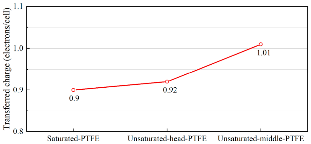
Figure 3 presents the interfacial charge transfer amounts between Al and three polymers, namely saturated-PTFE, unsaturated-head-PTFE, and unsaturated-middle-PTFE. A positive value indicates electron transfer from Al to the polymer. The results reveal that the interfacial charge transfer capacity follows the order of unsaturated-middle-PTFE > unsaturated-head-PTFE > saturated-PTFE, which is in excellent agreement with the findings reported in Ref. [48]. Although these polymers share the same backbone structure, intrinsic saturated-PTFE lacks double bonds, whereas the two modified variants differ solely in the location of their unsaturated bonds. This strongly suggests that both the introduction and spatial distribution of unsaturated bonds play a critical role in dictating interfacial charge transfer. To elucidate the underlying mechanism, an Al/single-chain-polymer model and an Al/molecular monomer model were further constructed. Comprehensive analyses were conducted from multiple perspectives, including electrostatic potential distribution, frontier molecular orbitals, and electronic density of states. The analytical results demonstrate that the HOMO and LUMO energy levels exert a decisive effect on the charge transfer process.

3.1. Charge Transfer Analysis for Al/Amorphous-Polymer Interface

Based on the previously optimized amorphous Al/polymer models, the interfacial charge transfer behavior during contact was simulated. First, Hirshfeld charge population analysis [49], implemented in the CASTEP module, was adopted to partition electron density within the amorphous polymers and quantify the charge transfer for each atom. The total interfacial charge transfer was then obtained by summing these individual atomic values. As listed in Table 1, the absolute interfacial charge densities for the Al/saturated-PTFE, Al/unsaturated-head-PTFE, and Al/unsaturated-middle-PTFE configurations are 51.45, 57.73, and 63.37 nC/mm2, respectively. Compared with the Al/saturated-PTFE interface, both modified configurations exhibit a marked increase in charge density, confirming that introducing unsaturated bonds significantly enhances interfacial charge transfer.
Because the present ideal model assumes a flat, homogeneous interface without accounting for complex real-world conditions, the calculated charge density is higher than experimental values. This discrepancy primarily stems from three factors. First, electron tunneling and backflow during interface separation cause partial charge loss [50]; second, real material surfaces typically exhibit a “mosaic-like” distribution of alternating positive and negative charges, making the macroscopically averaged net charge significantly lower than that predicted for homogeneous surfaces [51]; finally, naturally occurring nanoscale asperities substantially reduce the actual contact area, further widening the gap between calculated and measured values [52]. Despite differences in absolute values, the simulated charge transfer trends during friction and separation agree well with experimental observations [9], and their magnitude aligns with the simulation results by Wu et al. [47], validating the reliability of this computational model.
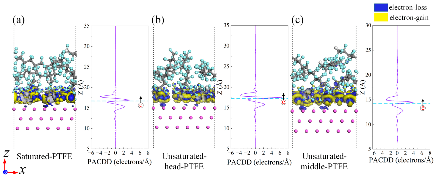
To further elucidate the charge redistribution at the interface, the charge density difference (CDD) and planar-averaged charge density difference (PACDD) along the z -direction were calculated using the CASTEP module. Analysis of the CDD plots clearly reveals the spatial redistribution of the atomic electron cloud density during CE. As illustrated in Figure 4, the yellow iso-surfaces in the CDD spatial distribution plots denote electron accumulation regions, while the green iso-surfaces correspond to electron depletion regions. The charge density difference can be defined as [47,53]:
ρ d i f f = ρ A l / p o l y m e r ρ p o l y m e r ρ A l
where ρ d i f f represents the differential charge density, ρ A l / p o l y m e r denotes the interfacial charge density of the Al/polymer complex, and ρ p o l y m e r and ρ A l correspond to the individual charge densities of isolated polymer and Al systems, respectively. CDD plots visually reveal the spatial rearrangement of electron clouds before and after contact via the net variation in electron density, facilitating the analysis of charge transfer directions during interfacial electronic coupling. To quantitatively characterize the interfacial charge transfer properties, the PACDD along the direction perpendicular to the interface (the z -axis), denoted as ρ d i f f z , was calculated in this work. The expression for ρ d i f f z is defined as follows [54]:
ρ d i f f z = ρ A l / p o l y m e r ρ A l ρ P o l y m e r d x d y
The PACDD distribution curves clearly demonstrate that charge transfer is confined to the nanoscale region of the contact interface. As illustrated in Figure 4, electron accumulation and depletion regions coexist on the polymer surface across all three configurations, whereas only electron depletion regions are observed on the Al surface. This reveals that Al atoms lose electrons, transferring charge from metallic Al to the polymer, which acts as an overall electron acceptor. Furthermore, electron accumulation and depletion predominantly occur at the outermost atoms of both the Al substrate and the polymer surface. Such charge transfer originates from the tendency to balance the orbital energy level difference across the two-phase contact interface, with Al serving as the electron donor in this process. The trends obtained from our calculations are in good agreement with published experimental results [55], which strongly validates the reliability of the theoretical model proposed in this work. Given the simultaneous electron gain and loss on the polymer surface, two distinct electronic behaviors can be identified at the interface: interfacial electron transfer from the Al substrate to the polymer surface, and internal charge redistribution within the polymer itself.

3.2. Charge Transfer Analysis for Al/Single-Chain-Polymer Interface

After clarifying the interfacial charge transfer direction, the net charge transfer of polymer segments along the z -axis was quantified relative to the interface center (the reference origin) to dissect the differences in CE between the three polymers and Al. As shown in Figure 3, all polymers are negatively charged after contact, with their electron-harvesting capabilities following the order: saturated-PTFE < unsaturated-head-PTFE < unsaturated-middle-PTFE. Because these amorphous polymers share an identical molecular skeleton and differ only in the number and introduction sites of unsaturated bonds, the presence and spatial distribution of these bonds clearly modulate interfacial charge transfer. Specifically, saturated-PTFE exhibits a notably weaker electron-harvesting capability than the modified variants. The introduction of unsaturated bonds thus remarkably enhances the polymer’s electron affinity and trapping capacity, demonstrating their pivotal role in regulating CE.

3.2.1. CDD Between Three Structural Configurations of PTFE Single-Chains and Al

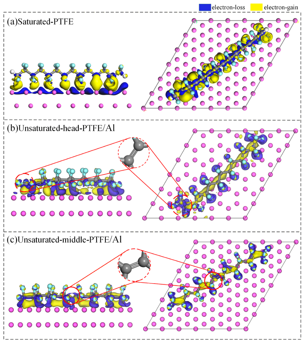
Although the amorphous models capture overall behavior, the intricate stacking of molecular chains produces overlapping electron accumulation and depletion regions at the interface. This complexity makes it difficult to pinpoint exact charge transfer sites or systematically summarize the governing rules. To elucidate how unsaturated bonds function during CE, the model was simplified using single-chain polymer/Al contact configurations for subsequent analyses [47,56,57]. Figure 5 presents the CDD results for the three single-chain PTFE configurations in contact with Al.
As intuitively reflected by the CDD distributions in Figure 5, the backbone carbon atoms exhibit prominent electron enrichment and act as primary electron acceptors upon contact with the Al surface. Notably, in PTFE systems containing unsaturated bonds, the C=C double bond sites serve as the dominant electron-accumulating regions (yellow areas) owing to their distinctive electronic structure. In contrast, remarkable electron depletion regions (blue areas) form on the Al surface and around the highly electronegative fluorine atoms. This localized charge redistribution visually confirms the direction of electron migration across the interface and aligns with our previous theoretical findings.

3.2.2. Electrostatic Potential and Frontier Orbital Reveals Active Sites for Electron Transfer

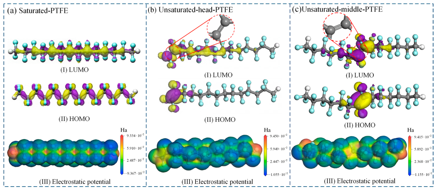
To clarify the intrinsic correlations between electron accumulation/depletion regions, frontier molecular orbitals, and electrostatic potentials, as well as to identify the dominant electron donor and acceptor atoms, frontier molecular orbital and electrostatic potential distribution analyses were performed for each single-chain structure, with the results presented in Figure 6. As reported by Wu et al. [57], the LUMO acts as the electron acceptor orbital, while the HOMO serves as the electron donor orbital.
The pristine and modified PTFE single chains exhibit distinctly different orbital localization behaviors. For the saturated-PTFE chain, the LUMO is mainly localized on the backbone C atoms, whereas the HOMO is predominantly distributed over the F groups. This phenomenon originates from the difference in electron-donating and electron-accepting abilities within the saturated C–F bonds; the strong electron-withdrawing effect of F atoms tightly confines valence electrons, localizing the HOMO on fluorine sites, while the electron-deficient backbone C atoms correspondingly host the LUMO.
In contrast, for the carbon–carbon double bond-containing unsaturated-head-PTFE and unsaturated-middle-PTFE chains, both HOMO and LUMO exhibit high spatial co-localization at the C=C double bond sites. Specifically, their LUMOs are highly concentrated on the double bonded C atoms with a minor distribution on adjacent C atoms, while their HOMOs are primarily located on the C=C carbon atoms and the attached F groups. This dual localization originates from the electronic structure of the C=C double bond, which consists of a strong σ bond and a localizable π bond. The high-energy π electrons function as electron donors that dictate the HOMO distribution; meanwhile, the empty π * antibonding orbital, possessing a lower energy level than the saturated backbone’s σ * orbital, exhibits an excellent electron-accepting capacity that confines the LUMO. Consequently, both frontier molecular orbitals are highly localized at the unsaturated double-bond region.
In molecular electrostatic potential maps, regions with negative electrostatic potential generally exhibit a strong electron-donating capacity, whereas those with positive electrostatic potential tend to act as electron acceptors and attract negatively charged species. As shown in Figure 6, the three PTFE single-chain structures display distinct electrostatic potential distribution characteristics. For saturated-PTFE, the maximum electrostatic potential is located on the backbone carbon atoms. In contrast, for the unsaturated-head-PTFE and unsaturated-middle-PTFE modified variants, the carbon atoms at the C=C double bond sites possess the highest electrostatic potential across the entire molecule. Although positive electrostatic potential is also observed around other carbon atoms, their values are substantially lower than those of the double-bonded carbons, confirming that C=C sites exert a stronger attraction on electrons and deliver superior electron-capturing performance.
Furthermore, the overall electrostatic potential scale shows that C=C-modified PTFE single chains possess higher electrostatic potential than saturated-PTFE, reinforcing that introducing unsaturated bonds enhances the polymer’s electron-trapping ability. Importantly, the dominant electron-accepting regions identified by electrostatic potential analysis agree remarkably well with the LUMO distributions discussed above. Similarly, negative electrostatic potential is predominantly localized on the fluorine atoms across all three models, consistent with the HOMO localization features.

3.2.3. Density of States Reveals the Composition of Frontier Orbitals

Comprehensive DOS and PDOS analyses provide intuitive insights into the electronic energy level distribution, atomic composition of frontier orbitals, and charge localization characteristics of the system. This approach aligns with standard computational paradigms for insulating polymers and maintains methodological consistency with our single-chain models, ensuring valid structural comparisons.
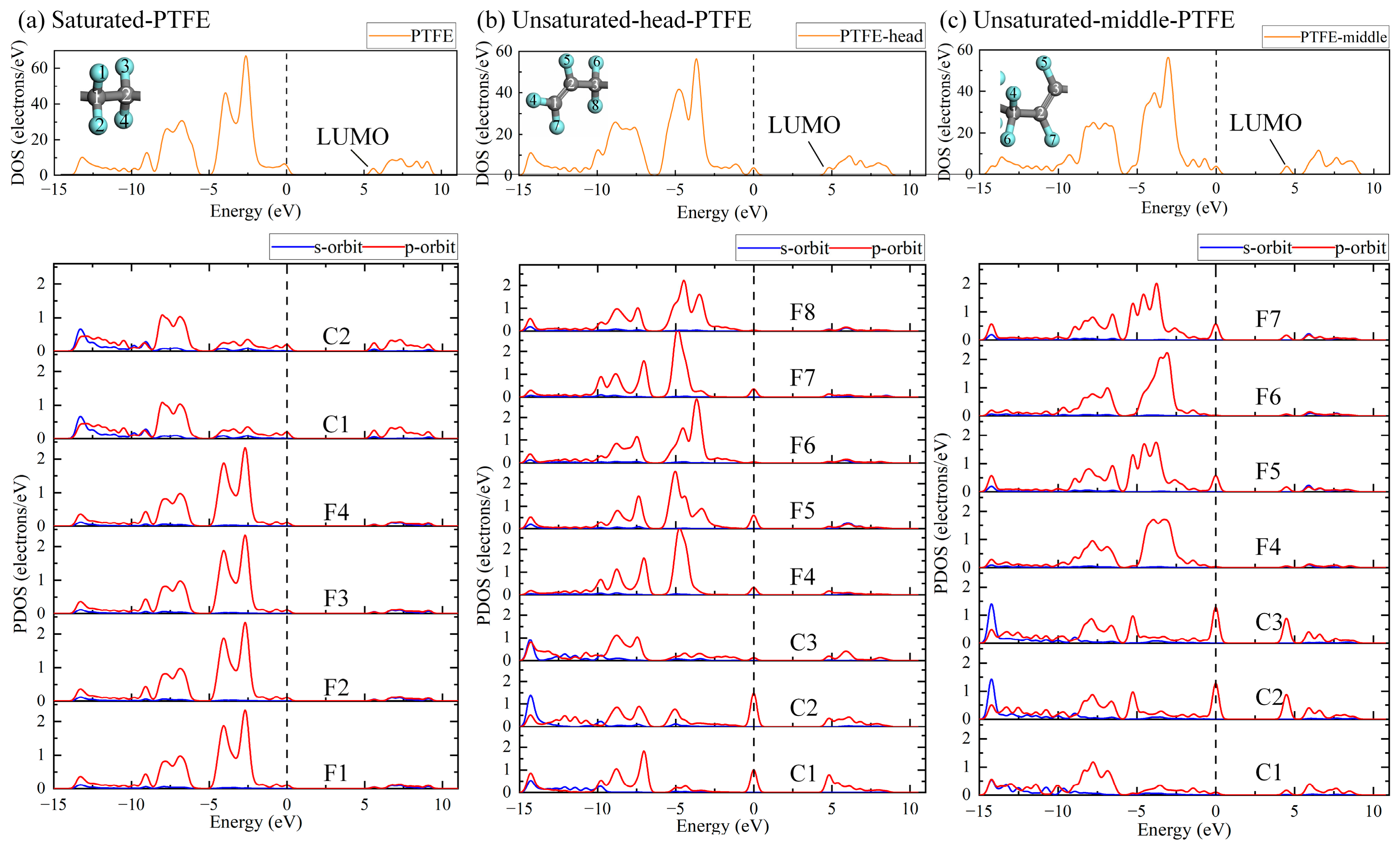
To explore the electronic structure from the macroscopic bands’ structure down to the microscopic atomic orbitals, DOS and PDOS calculations were performed (Figure 7). To eliminate boundary effects from terminal groups, the fourth central repeating unit of pristine saturated-PTFE was selected. For the C=C-modified PTFE chains, characteristic fragments containing double bonds and their adjacent carbons were extracted to assess the orbital regulation induced by unsaturated bonds. Benefiting from the intrinsic charge localization in insulating polymers, this fragment-based approach is well-suited for our system and has been validated by Li et al. [58] for similar insulating materials.
The DOS curves of the original structures before contact exhibit sharp and discrete characteristic peaks, which are typical signatures of strong electron localization in insulating materials. With the Fermi level set to 0 eV, the first characteristic peak above 0 eV corresponds to the LUMO, whereas the peak directly below represents the HOMO. PDOS further quantifies the contribution of each atomic orbital to the frontier orbitals. Combined with the atomic labels in the inset, the core atoms constructing the HOMO and LUMO can be accurately identified.
For saturated-PTFE, the highly symmetric single-chain structure enables fluorine atoms to exert a uniform electronic effect on the carbon backbone. PDOS results reveal that the p-orbitals of C1 and C2 atoms dominate the contribution to the LUMO, while the s- and p-orbitals of fluorine atoms contribute negligibly. This demonstrates that the LUMO is mainly localized on the carbon backbone, with carbon atoms serving as the primary electron-accepting sites. Notably, the DOS at the LUMO energy level is considerably higher than that at the HOMO level, further validating the typical electron-accepting character of saturated-PTFE.
With regard to unsaturated-head-PTFE with a terminal C=C double bond, the p-orbitals of the double-bonded C1 and C2 atoms, alongside the adjacent C3 atom, dominate the LUMO contribution, with fluorine atoms showing negligible participation. For unsaturated-middle-PTFE with a C=C double bond located in the middle of the molecular chain, the LUMO mainly originates from the p-orbitals of the double-bonded carbons and their attached fluorine atoms. Among these orbitals, C1 and C2 contribute the most, aligning remarkably well with the LUMO spatial distribution in Figure 6. Combining the PDOS orbital composition and spatial LUMO distribution, it can be inferred that the molecular orbitals constituting the LUMO are primarily π orbitals formed by the overlap of p-orbitals from C1 and C2. This indicates that π orbitals are more prone to act as electron-accepting orbitals than σ orbitals. Because single-bonded carbon atoms only form σ orbitals, the existence of π orbitals explains why double-bonded carbons yield a far greater contribution to the LUMO than single-bonded ones.

3.3. Charge Transfer Analysis for Al/Polymer–Monomer Interface

To further clarify the effect of C=C double bonds on interfacial electron transfer, directly verify theoretical predictions, and justify selecting double-bonded fragments in the PDOS analysis, quantitative charge transfer calculations were performed for polymer monomers in contact with metallic Al. Because amorphous PTFE is an insulating polymer with highly localized electrons along its chain, using monomer models that capture local chemical defects to represent long chains serves as a reasonable and effective strategy for investigating interfacial CE.
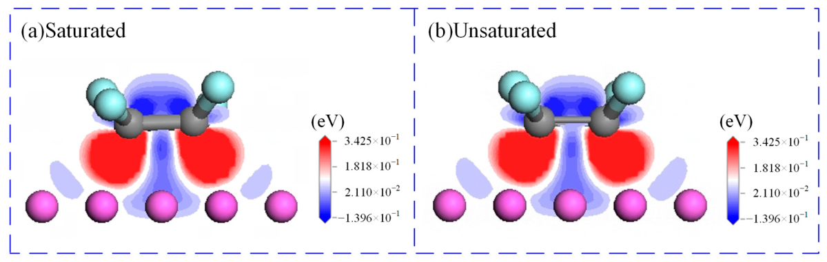
Two contact configurations were constructed: pristine saturated-PTFE monomer/Al, and C=C defect-containing PTFE monomer/Al. Both systems underwent global geometric optimization using the COMPASS force field until the total energy reached a minimum and interfacial forces approached zero; the resulting atomic equilibrium distance defined the final separation (Figure 8). First-principles DFT calculations were then conducted using parameters identical to earlier sections, and the resulting CDD maps are shown in Figure 8.
As displayed in Figure 8, charge accumulation regions (red) concentrate predominantly around the C atoms of the PTFE monomers, whereas the charge depletion zones (blue) distribute widely across the Al surface. This 3D profile confirms that both pristine and C=C-modified PTFE monomers act as electron acceptors, while the Al substrate serves as the electron donor. Furthermore, CDD intensity scales indicate that the C=C defect-containing monomer exhibits substantially stronger charge accumulation at the interface than its pristine counterpart. Concurrently, quantitative Hirshfeld charge population analysis reveals that the interfacial electron transfer increases from 0.28 e for the pristine monomer to 0.33 e for the C=C-modified monomer. Combining the visual graphics and quantitative data, it can be concluded that the introduction of the carbon–carbon double bond effectively alleviates the local electron localization effect and promotes electron delocalization, thereby reinforcing the electron-accepting capability of the polymer and ultimately leading to a remarkable enhancement in the interfacial contact charge transfer.
Notably, C=C double bonds in polymers modulate electron-donating and electron-accepting abilities by altering inherent HOMO/LUMO distributions, a trend rooted in the intrinsic material properties. While replacing the substrate with metals of different work functions (e.g., Cu, Ag, and Au) alters the magnitude of interfacial charge transfer, it does not change the regulating effect of terminal or internal defects. Previous studies on the CE of PTFE with various metals show that the Al/PTFE interface generates a substantially higher surface charge density than its Cu/PTFE counterpart, thereby yielding a more pronounced charge transfer signal [59]. Therefore, an Al substrate provides a more pronounced electron transfer signal. Furthermore, the Al/PTFE pair is a classic, high-performance system in triboelectrification research, supported by the extensive theoretical and experimental literature. Based on these considerations, this work employs the standard Al/PTFE system as a benchmark to isolate polymer structural defects as the sole variable. The synergistic coupling between different metal substrates and structural defects will be explored in future work.

4. Conclusions

In this work, first-principles calculations based on DFT were performed to systematically investigate the microscopic CE process at the interfaces between metallic Al and three types of PTFE, including saturated-PTFE and two modified PTFE variants with C=C double bonds at different positions. The intrinsic mechanism by which unsaturated bonds modulate interfacial charge transfer was revealed. We initially established the adsorption configurations of PTFE unit cells on the Al substrate to quantitatively analyze how unsaturated structures affect the direction and magnitude of interfacial charge transfer. Furthermore, combined with single-chain and monomer interfacial models, the microscopic physical mechanism of CE was elaborated from multiple perspectives involving interfacial electron migration, structural effects of unsaturated bonds, and molecular electronic properties.
The results demonstrate that charge transfer primarily occurs between the outermost atoms at the metal/polymer interface. Compared with saturated-PTFE, both unsaturated-head-PTFE and unsaturated-middle-PTFE exhibit enhanced electron-capturing capabilities. Furthermore, the charge transfer efficiency shows a strong dependence on the spatial location of C=C double bonds, following the decreasing order of: unsaturated-middle-PTFE > unsaturated-head-PTFE > saturated-PTFE. Electron density difference analysis directly visualizes the electron transfer pathway from the Al substrate to the polymer layer. Concurrently, frontier molecular orbital analysis confirms that the electron-donating performance of the polymer is governed by the HOMO energy level, while its electron-accepting capability is strictly dictated by the LUMO characteristics.
This work clarifies how C=C unsaturated bonds modulate interfacial charge transfer, providing microscopic theoretical guidance for designing high-performance TENGs dielectric materials through double bond position engineering and LUMO energy level tuning. Several limitations, however, remain in the present study. First, the current analysis of charge transfer trends remains mainly qualitative; quantitative correlations are yet to be established. Second, the simulations rely on ideal, flat interfaces under static, room-temperature vacuum conditions, omitting practical operating factors such as charge leakage, surface roughness, dynamic friction, and wear.
Future research will be carried out in two aspects. On the one hand, quantitative relationships between LUMO characteristics and charge transfer quantity will be constructed. On the other hand, multi-physics coupling analysis will be performed by combining molecular dynamics simulations and physical experiments. Meanwhile, carbon–carbon double bond defects can be fabricated through various surface modification strategies, including magnetron sputtering, plasma treatment, ion irradiation, ultraviolet modification and chemical functionalization. The theories proposed in this paper can provide guidance for the practical modification of polymer triboelectric materials.

Author Contributions

Methodology, T.T., C.W. and Y.F.; Software, T.T., B.Z. and Y.F.; Investigation, T.T. and X.Z.; Writing—original draft, T.T. and X.Z.; Writing—review and editing, T.T. and B.Z.; Visualization, C.W. and Y.F.; Project administration, B.Z.; Funding acquisition, P.X. All authors have read and agreed to the published version of the manuscript.

Funding

This research work was supported by the National Natural Science Foundation of China (52375226, U22A2012, 51909254).

Data Availability Statement

The authors declare that all the relevant data are available within the paper or from the corresponding author upon reasonable request.

Conflicts of Interest

The authors declare no conflicts of interest.

References

  1. Lacks, D.J.; Shinbrot, T. Long-standing and unresolved issues in triboelectric charging. Nat. Rev. Chem. 2019, 3, 465–476. [Google Scholar] [CrossRef] [Scilit]
  2. Wu, C.; Wang, A.C.; Ding, W.; Guo, H.; Wang, Z.L. Triboelectric Nanogenerator: A Foundation of the Energy for the New Era. Adv. Energy Mater. 2019, 9, 1802906. [Google Scholar] [CrossRef] [Scilit]
  3. Tang, X.; Hou, W.; Zheng, Q.; Fang, L.; Zhu, R.; Zheng, L. Self-powered wind sensor based on triboelectric nanogenerator for detecting breeze vibration on electric transmission lines. Nano Energy 2022, 99, 107412. [Google Scholar] [CrossRef] [Scilit]
  4. Liang, X.; Liu, Z.; Feng, Y.; Han, J.; Li, L.; An, J.; Chen, P.; Jiang, T.; Wang, Z.L. Spherical triboelectric nanogenerator based on spring-assisted swing structure for effective water wave energy harvesting. Nano Energy 2021, 83, 105836. [Google Scholar] [CrossRef] [Scilit]
  5. Rodrigues, C.; Ramos, M.; Esteves, R.; Correia, J.; Clemente, D.; Gonçalves, F.; Mathias, N.; Gomes, M.; Silva, J.; Duarte, C.; et al. Integrated study of triboelectric nanogenerator for ocean wave energy harvesting: Performance assessment in realistic sea conditions. Nano Energy 2021, 84, 105890. [Google Scholar] [CrossRef] [Scilit]
  6. Doganay, D.; Durukan, M.B.; Cugunlular, M.; Cakir, O.; Cicek, M.O.; Demircioglu, O.; Wei, D.; Unalan, H.E. Triboelectric nanogenerators from fundamentals to applications. Nano Energy 2025, 138, 110825. [Google Scholar] [CrossRef] [Scilit]
  7. Khanapurarm, U.K.; Rani, G.M.; Panda, S.; Charoonsuk, T.; Mistewicz, K.; Hajra, S.; Kaja, K.R.; Umapathi, R.; Sriphan, S.; Jała, J.; et al. Harvesting energy from friction: The revolutionary decade of triboelectric nanogenerators. Adv. Powder Mater. 2026, 5, 100373. [Google Scholar] [CrossRef] [Scilit]
  8. Tian, T.; Zhao, B.; Wang, Y.; Huang, S.; Ju, X.; Fan, Y. First-Principles Study on Interfacial Triboelectrification Between Water and Halogen-Functionalized Polymer Surfaces. Lubricants 2025, 13, 303. [Google Scholar] [CrossRef] [Scilit]
  9. Li, S.; Nie, J.; Shi, Y.; Tao, X.; Wang, F.; Tian, J.; Lin, S.; Chen, X.; Wang, Z.L. Contributions of Different Functional Groups to Contact Electrification of Polymers. Adv. Mater. 2020, 32, e2001307. [Google Scholar] [CrossRef] [Scilit] [PubMed]
  10. Zhao, B.; Wang, Y.; Huang, S.; Tian, T.; Liao, X.; Wang, W.; Li, Z. High-durability pendulum-structured TENG-EMG hybrid with stacked liquid-solid triboelectric layers for efficient low-frequency ocean wave energy capture. Chem. Eng. J. 2025, 523, 168505. [Google Scholar] [CrossRef] [Scilit]
  11. Yoo, D.; Park, S.-C.; Lee, S.; Sim, J.-Y.; Song, I.; Choi, D.; Lim, H.; Kim, D.S. Biomimetic anti-reflective triboelectric nanogenerator for concurrent harvesting of solar and raindrop energies. Nano Energy 2019, 57, 424–431. [Google Scholar] [CrossRef] [Scilit]
  12. Wang, Z.L.; Wang, A.C. On the origin of contact-electrification. Mater. Today 2019, 30, 34–51. [Google Scholar] [CrossRef] [Scilit]
  13. Lacks, D.J.; Duff, N.; Kumar, S.K. Nonequilibrium Accumulation of Surface Species and Triboelectric Charging in Single Component Particulate Systems. Phys. Rev. Lett. 2008, 100, 188305. [Google Scholar] [CrossRef] [Scilit] [PubMed]
  14. Pan, S.; Zhang, Z. Fundamental theories and basic principles of triboelectric effect: A review. Friction 2018, 7, 2–17. [Google Scholar] [CrossRef] [Scilit]
  15. Wu, J.; Wen, Q.; Zhu, W. Role of electrostatic force induced by contact electrification on the adhesion of triboelectric materials: An atomic scale investigation. Tribol. Int. 2026, 214, 111263. [Google Scholar] [CrossRef] [Scilit]
  16. Chen, S.W.; Cao, X.; Wang, N.; Ma, L.; Zhu, H.R.; Willander, M.; Jie, Y.; Wang, Z.L. An Ultrathin Flexible Single-Electrode Triboelectric-Nanogenerator for Mechanical Energy Harvesting and Instantaneous Force Sensing. Adv. Energy Mater. 2017, 7, 1601255. [Google Scholar] [CrossRef] [Scilit]
  17. Li, H.Y.; Su, L.; Kuang, S.Y.; Pan, C.F.; Zhu, G.; Wang, Z.L. Significant Enhancement of Triboelectric Charge Density by Fluorinated Surface Modification in Nanoscale for Converting Mechanical Energy. Adv. Funct. Mater. 2015, 25, 5691–5697. [Google Scholar] [CrossRef] [Scilit]
  18. Shin, S.-H.; Bae, Y.E.; Moon, H.K.; Kim, J.; Choi, S.-H.; Kim, Y.; Yoon, H.J.; Lee, M.H.; Nah, J. Formation of Triboelectric Series via Atomic-Level Surface Functionalization for Triboelectric Energy Harvesting. ACS Nano 2017, 11, 6131–6138. [Google Scholar] [CrossRef] [Scilit] [PubMed]
  19. Fatti, G.; Cavin, J.; Ko, H.; Mishra, R.; Dini, D.; Cho, S.B. First-Principles Models of Triboelectrification. Small Methods 2026, 10, e01782. [Google Scholar] [CrossRef] [Scilit] [PubMed]
  20. Šutka, A.; Mālnieks, K.; Lapčinskis, L.; Kaufelde, P.; Linarts, A.; Bērziņa, A.; Zābels, R.; Jurķāns, V.; Gorņevs, I.; Blūms, J.; et al. The role of intermolecular forces in contact electrification on polymer surfaces and triboelectric nanogenerators. Energy Environ. Sci. 2019, 12, 2417–2421. [Google Scholar] [CrossRef] [Scilit]
  21. Verners, O.; Lapčinskis, L.; Sherrell, P.C.; Šutka, A. Contact Electrification at Dielectric Polymer Interfaces: On Bond Scission, Material Transfer, and Electron Transfer. Adv. Mater. Interfaces 2023, 10, 2300562. [Google Scholar] [CrossRef] [Scilit]
  22. Mizzi, C.A.; Lin, A.Y.W.; Marks, L.D. Does Flexoelectricity Drive Triboelectricity? Phys. Rev. Lett. 2019, 123, 116103. [Google Scholar] [CrossRef] [Scilit] [PubMed]
  23. Mizzi, C.A.; Marks, L.D. When Flexoelectricity Drives Triboelectricity. Nano Lett. 2022, 22, 3939–3945. [Google Scholar] [CrossRef] [Scilit] [PubMed]
  24. Olson, K.P.; Mizzi, C.A.; Marks, L.D. Band Bending and Ratcheting Explain Triboelectricity in a Flexoelectric Contact Diode. Nano Lett. 2022, 22, 3914–3921. [Google Scholar] [CrossRef] [Scilit] [PubMed]
  25. Olson, K.P.; Marks, L.D. Is triboelectricity confusing, confused or complex? Rep. Prog. Phys. 2025, 88, 104501. [Google Scholar] [CrossRef] [Scilit] [PubMed]
  26. Xu, G.; Guan, D.; Fu, J.; Li, X.; Li, A.; Ding, W.; Zi, Y. Density of Surface States: Another Key Contributing Factor in Triboelectric Charge Generation. ACS Appl. Mater. Interfaces 2022, 14, 5355–5362. [Google Scholar] [CrossRef] [Scilit] [PubMed]
  27. Su, Y.; Berbille, A.; Wang, Z.L.; Tang, W. Water-solid contact electrification and catalysis adjusted by surface functional groups. Nano Res. 2023, 17, 3344–3351. [Google Scholar] [CrossRef] [Scilit]
  28. Liu, J.; Zhang, F.; Xu, J.; Jia, S.; Cui, N.; Yang, R.; Wang, W.; Gu, L. Unveiling the synergistic mechanism of C-F and C-Cl bonds in enhancing the triboelectric performance of fluorinated polymers. Nat. Commun. 2026, 17, 3698. [Google Scholar] [CrossRef] [Scilit] [PubMed]
  29. Wu, J.; Cao, J.; Bi, H.; Zhu, W.; Rong, J.; Xu, Y. Effect of external electric field on copper/silica contact electrification and adhesion: Insight from first-principles and molecular mechanics investigations. J. Phys. D Appl. Phys. 2024, 57, 385305. [Google Scholar] [CrossRef] [Scilit]
  30. Li, S.; Fan, Y.; Chen, H.; Nie, J.; Liang, Y.; Tao, X.; Zhang, J.; Chen, X.; Fu, E.; Wang, Z.L. Manipulating the triboelectric surface charge density of polymers by low-energy helium ion irradiation/implantation. Energy Environ. Sci. 2020, 13, 896–907. [Google Scholar] [CrossRef] [Scilit]
  31. Mayrhofer, L.; Mokhtar, M.; Walter, M.; Moseler, M. Oxidized Mechanoradicals Drive Triboelectricity in Polytetrafluoroethylene: A First Principle Understanding. J. Phys. Chem. C 2025, 129, 19592–19607. [Google Scholar] [CrossRef] [Scilit]
  32. Hohenberg, P.; Kohn, W. Inhomogeneous Electron Gas. Phys. Rev. 1964, 136, B864–B871. [Google Scholar] [CrossRef] [Scilit]
  33. Parr, R.G.; Weitao, Y. Density-Functional Theory of Atoms and Molecules; Oxford University Press: Oxford, UK, 1995. [Google Scholar]
  34. Perdew, J.P.; Levy, M. Physical Content of the Exact Kohn-Sham Orbital Energies: Band Gaps and Derivative Discontinuities. Phys. Rev. Lett. 1983, 51, 1884–1887. [Google Scholar] [CrossRef] [Scilit]
  35. Kohn, W.; Sham, L.J. Self-Consistent Equations Including Exchange and Correlation Effects. Phys. Rev. 1965, 140, A1133–A1138. [Google Scholar] [CrossRef] [Scilit]
  36. Issa, Y.M.; Abdel-Latif, S.A.; El-Ansary, A.L.; Hassib, H.B. The synthesis, spectroscopic characterization, DFT/TD-DFT/PCM calculations of the molecular structure and NBO of the novel charge-transfer complexes of pyrazine Schiff base derivatives with aromatic nitro compounds. New J. Chem. 2021, 45, 1482–1499. [Google Scholar] [CrossRef] [Scilit]
  37. Abdel-Latif, S.A.; Moustafa, H. Synthesis, characterization, electronic structure, and non-linear optical properties (NLO) of Mn(II), Co(II), Ni(II), Cu(II) and Zn(II) complexes with 5-phenylazo-8-hydroxyquinoline using DFT approach. Appl. Organomet. Chem. 2017, 31, e3876. [Google Scholar] [CrossRef] [Scilit]
  38. Darweesh, A.F.; El-Fatah, N.A.A.; Abdel-Latif, S.A.; Abdelhamid, I.A.; Elwahy, A.H.M.; Salem, M.E. Synthesis and DTF studies of novel aminoimidazodipyridines using 2-(3H-imidazo [4,5-b]pyridin-2-yl)acetonitrile as an efficient key precursor. Arkivoc 2021, 2021, 23–37. [Google Scholar] [CrossRef] [Scilit]
  39. Li, L.; Wang, X.; Zhu, P.; Li, H.; Wang, F.; Wu, J. The electron transfer mechanism between metal and amorphous polymers in humidity environment for triboelectric nanogenerator. Nano Energy 2020, 70, 104476. [Google Scholar] [CrossRef] [Scilit]
  40. Lee, J.W.; Cho, H.J.; Chun, J.; Kim, K.N.; Kim, S.; Ahn, C.W.; Kim, I.W.; Kim, J.-Y.; Kim, S.-W.; Yang, C.; et al. Robust nanogenerators based on graft copolymersvia control of dielectrics for remarkable output power enhancement. Sci. Adv. 2017, 3, 1602902. [Google Scholar] [CrossRef] [Scilit]
  41. Liu, W.; Yang, C.-L.; Zhu, Y.-T.; Wang, M.-S. Interactions between Single-Walled Carbon Nanotubes and Polyethylene/Polypropylene/Polystyrene/Poly(phenylacetylene)/Poly(p-phenylenevinylene) Considering Repeat Unit Arrangements and Conformations: A Molecular Dynamics Simulation Study. J. Phys. Chem. C 2008, 112, 1803–1811. [Google Scholar] [CrossRef] [Scilit]
  42. Chawla, R.; Sharma, S. Molecular dynamics simulation of carbon nanotube pull-out from polyethylene matrix. Compos. Sci. Technol. 2017, 144, 169–177. [Google Scholar] [CrossRef] [Scilit]
  43. Pan, D.; Zhu, K.; Zhang, Y.; Sun, L.; Hao, X. First principles and molecular dynamics simulation investigation of mechanical properties of the PTFE/graphene composites. Compos. Part B Eng. 2022, 242, 110050. [Google Scholar] [CrossRef] [Scilit]
  44. Sun, H. COMPASS: An ab initio force-field optimized for condensed-phase applications overview with details on alkane and benzene compounds. J. Phys. Chem. B 1998, 102, 7338–7364. [Google Scholar] [CrossRef] [Scilit]
  45. Segall, M.D.; Lindan, P.J.; Probert, M.A.; Pickard, C.J.; Hasnip, P.J.; Clark, S.J.; Payne, M.C. First-principles simulation ideas, illustrations and the CASTEP code. J. Phys. Condens. Matter 2002, 14, 2717–2744. [Google Scholar] [CrossRef] [Scilit]
  46. John, P.; Perdew, K.B.; Ernzerhof, M. Generalized gradient approximation made simple. Phys. Rev. 1996, 77, 3865. [Google Scholar] [CrossRef] [Scilit]
  47. Wu, J.; Wang, X.; Li, H.; Wang, F.; Hu, Y. First-principles investigations on the contact electrification mechanism between metal and amorphous polymers for triboelectric nanogenerators. Nano Energy 2019, 63, 103864. [Google Scholar] [CrossRef] [Scilit]
  48. Wei, X.; Zhao, Z.; Zhang, C.; Yuan, W.; Wu, Z.; Wang, J.; Wang, Z.L. All-Weather Droplet-Based Triboelectric Nanogenerator for Wave Energy Harvesting. ACS Nano 2021, 15, 13200–13208. [Google Scholar] [CrossRef] [Scilit] [PubMed]
  49. De Proft, F.; Van Alsenoy, C.; Peeters, A.; Langenaeker, W.; Geerlings, P. Atomic charges, dipole moments, and Fukui functions using the Hirshfeld partitioning of the electron density. J. Comput. Chem. 2002, 23, 1198–1209. [Google Scholar] [CrossRef] [Scilit] [PubMed]
  50. Ko, H.; Lim, Y.-w.; Han, S.; Jeong, C.K.; Cho, S.B. Triboelectrification: Backflow and Stuck Charges Are Key. ACS Energy Lett. 2021, 6, 2792–2799. [Google Scholar] [CrossRef] [Scilit]
  51. Baytekin, H.T.; Patashinski, A.Z.; Branicki, M.; Baytekin, B.; Soh, S.; Grzybowski, B.A. The Mosaic of Surface Charge in Contact Electrification. Science 2011, 333, 308–312. [Google Scholar] [CrossRef] [Scilit] [PubMed]
  52. Liang, X.M.; Xing, Y.Z.; Li, L.T.; Yuan, W.K.; Wang, G.F. An experimental study on the relation between friction force and real contact area. Sci. Rep. 2021, 11, 20366. [Google Scholar] [CrossRef] [Scilit] [PubMed]
  53. Yang, W.; Wang, X.; Li, H.; Wu, J.; Hu, Y. Comprehensive contact analysis for vertical-contact-mode triboelectric nanogenerators with micro-/nano-textured surfaces. Nano Energy 2018, 51, 241–249. [Google Scholar] [CrossRef] [Scilit]
  54. Li, L.; Wang, X.; Hu, Y.; Li, Z.; Wang, C.; Zhao, Z. Understanding the Ferroelectric Polymer–Metal Contact Electrification for Triboelectric Nanogenerator from Molecular and Electronic Structure. Adv. Funct. Mater. 2021, 32, 2109949. [Google Scholar] [CrossRef] [Scilit]
  55. Xiang, T.; Chen, X.; Sun, H.; Liu, D.; Jiang, Y.; Chen, S.; Xie, Y.; Zhang, S. Advances in liquid-solid triboelectric nanogenerators and its applications. J. Mater. Sci. Technol. 2025, 214, 153–169. [Google Scholar] [CrossRef] [Scilit]
  56. Nan, Y.; Shao, J.; Willatzen, M.; Wang, Z.L. Understanding Contact Electrification at Water/Polymer Interface. Research 2022, 2022, 9861463. [Google Scholar] [CrossRef] [Scilit] [PubMed]
  57. Wu, J.; Wang, X.; Li, H.; Wang, F.; Yang, W.; Hu, Y. Insights into the mechanism of metal-polymer contact electrification for triboelectric nanogenerator via first-principles investigations. Nano Energy 2018, 48, 607–616. [Google Scholar] [CrossRef] [Scilit]
  58. Li, L.-H.; Kontsevoi, O.Y.; Freeman, A.J. Atomic-Scale Understanding of the Interaction of Poly(3-hexylthiophene) with the NiO (100) Surface: A First-Principles Study. J. Phys. Chem. C 2014, 118, 20298–20305. [Google Scholar] [CrossRef] [Scilit]
  59. Wang, L.; Dong, Y.; Tao, J.; Ma, T.; Dai, Z. Study of the mechanisms of contact electrification and charge transfer between polytetrafluoroethylene and metals. J. Phys. D Appl. Phys. 2020, 53, 285302. [Google Scholar] [CrossRef] [Scilit]
Figure 1. (a) Chemical formulas of three polymers. (b) Schematic of Al/polymer contact electrification in TENG.
Lubricants 14 00291 g001
Figure 2. (a) Unit cell structures of three polymers. (b) Molecular configurations of three Al/polymer composite systems.
Lubricants 14 00291 g002
Figure 3. Charge transfer comparison for three polymer/Al contacts.
Lubricants 14 00291 g003
Figure 4. The charge density difference and corresponding planar average charge density difference in three amorphous polymer/Al interface systems: (a) saturated-PTFE/Al, (b) unsaturated-head-PTFE/Al, and (c) unsaturated-middle-PTFE/Al. The dashed lines represent the contact interface.
Lubricants 14 00291 g004
Figure 5. The charge density difference and corresponding planar average charge density difference in three single-chain polymer/Al interface systems: (a) saturated-PTFE/Al, (b) unsaturated-head-PTFE/Al, and (c) unsaturated-middle-PTFE/Al.
Lubricants 14 00291 g005
Figure 6. The lowest unoccupied molecular orbitals (LUMO), the highest occupied molecular orbitals (HOMO), and electrostatic potential of (a) saturated-PTFE, (b) unsaturated-head-PTFE, and (c) unsaturated-middle-PTFE.
Lubricants 14 00291 g006
Figure 7. The DOS for single-chain polymers and the PDOS for characteristic molecular fragments of (a) saturated-PTFE, (b) unsaturated-head-PTFE, and (c) unsaturated-middle-PTFE.
Lubricants 14 00291 g007
Figure 8. Contact configurations and corresponding CDD distributions of PTFE monomer/Al systems: (a) unsaturated structure, (b) saturated structure.
Lubricants 14 00291 g008
Table 1. Electronic density at the interface between three types of amorphous PTFE and metal.
Contact Material Pairs Al/Saturated-PTFEAl/Unsaturated-Head-PTFEAl/Unsaturated-Middle-PTFE
Interfacial charge density (nC/mm2)51.4557.7363.37
Disclaimer/Publisher’s Note: The statements, opinions and data contained in all publications are solely those of the individual author(s) and contributor(s) and not of MDPI and/or the editor(s). MDPI and/or the editor(s) disclaim responsibility for any injury to people or property resulting from any ideas, methods, instructions or products referred to in the content.