1. Introduction
As a fundamental component of human biomechanics, the bionic humanoid mechanical leg serves as the primary motion unit in humanoid robots. Owing to its specialized functional requirements, the mechanical structure must ensure high rigidity, excellent stability, and strong load-bearing capacity simultaneously. Due to the intricate mechanical architecture and the need to faithfully replicate human motion, this type of system has become a focal point of research in intelligent robotics and rehabilitation engineering. In most existing studies on the dynamics of bionic humanoid mechanical legs, kinematic joints are typically modeled as ideal, clearance-free connections. However, in practical applications, manufacturing tolerances and assembly errors inevitably introduce clearances in kinematic joints, which become critical factors affecting system performance. During operation, revolute joint clearances significantly compromise the mechanism’s stability, induce nonlinear impacts and vibrations at the joint interfaces, accelerate wear at the clearance sites, shorten service life, and may even lead to mechanical failure. Leveraging the structural generality of bionic humanoid legs, the research framework proposed in this study not only provides theoretical guidance for the design and maintenance of such mechanisms but also establishes a foundation for clinical applications involving complex systems such as exoskeletons, rehabilitation robots, surgical robots, and parallel rehabilitation platforms.
The dynamic effects induced by joint clearances have become a critical focus in the study of mechanical systems. Chen et al. [
1] developed and tested a dynamic model for a high-speed parallel manipulator with multiple 3D revolute joint clearances, examining key influencing factors. Yang et al. [
2] conducted numerical simulations to investigate the effects of changes in clearance size, trajectory planning, and loading conditions on the system’s performance. Bai et al. [
3] investigated the dynamic response of a slider–crank mechanism featuring two spatial revolute joint clearances and one planar prismatic clearance via combined simulation and experiments. Jiang et al. [
4] formulated a general approach for solving system dynamics involving both rotational and translational clearances, integrating dry friction and contact state detection within the Baumgarte stabilization framework. Javanfar et al. [
5] carried out dynamic modeling and analysis of a double-rocker four-bar mechanism, taking into account the presence of revolute joint clearances and frictional effects. Yang et al. [
6] investigated the nonlinear dynamic behavior of a serial robotic arm featuring two spatial revolute joint clearances, with particular attention to the location of the clearances and their interaction effects. Xin et al. [
7] carried out an in-depth investigation into the dynamic behavior, reliability, and wear characteristics of a rigid–flexible hybrid system with spatial revolute clearances, taking into account structural flexibility, clearance size, and multiple-clearance setups. Ma et al. [
8] established a spectral element-based modeling framework to study impact-induced dynamics in planar structures with single and multiple revolute joint clearances. Li et al. [
9] developed a dynamic analysis approach for studying the deployment process of Bennett linkages with revolute joint clearances and applied it to typical configuration cases. Varedi-Koulaei et al. [
10] examined the dynamic performance of planar mechanisms with joint clearances, focusing on how operating speed and clearance magnitude influence system behavior. Lou et al. [
11] analyzed how variations in clearance dimensions, input velocity, and friction conditions affect the acceleration characteristics of the slider. Kuang et al. [
12] indicates that the contact and impact occurring at the clearance have a significant effect on the dynamic performance of the dual-manipulator system. PI et al. [
13] presented a generalized multi-patch clearance model for revolute joints and analyzed its effects on both rigid and flexible mechanisms. Liu et al. [
14] applied fuzzy set theory to study the uncertainty relationship between joint tolerance levels and mechanical performance. Xiao et al. [
15] examined the influence of clearance size and actuation speed on the nonlinear dynamics of mechanical systems. Wei et al. [
16] developed a hybrid model integrating clearance contact dynamics, finite element methods, and rigid–flexible coupling to examine practical dynamics in cam–linkage multibody systems. Wang et al. [
17] investigated how crank speed, as well as the number, position, and magnitude of clearances, influence the wear behavior of systems with multiple clearances. Bai et al. [
18] established a normal contact force model for a radial clearance joint using a nonlinear contact force formulation and demonstrated that the presence of clearance significantly affects the dynamic characteristics of the gear-linkage mechanism. Chen et al. [
19] developed a model based on the Lagrange equations and conducted an in-depth analysis of the effects of clearance joints on the dynamic behavior of high-precision mechanisms.
During service, wear between the pin and bushing is inevitable, which alters the joint clearance and, in turn, affects the operational performance of the mechanism. Consequently, the wear characteristics of kinematic pairs with clearance have attracted extensive research attention. Ding et al. [
20] investigated the nonlinear contact force response and wear evolution under different excitation frequencies by considering asymmetric clearance. Jiang et al. [
21] explored the role of structural optimization in influencing the wear progression, dynamic response, and nonlinear phenomena in planar multilink systems subjected to clearance wear. Hou et al. [
22] analyzed the dynamic behavior of a 3-RSR parallel mechanism considering spherical joint clearance and wear progression. Fu et al. [
23] proposed a reliability-focused control framework for manipulators with clearance joints, incorporating the Archard model to represent wear-induced clearance growth. Gao et al. [
24] proposed an immune algorithm-based optimization approach to assess the interplay between joint wear and system dynamics, accounting for nonlinear behavior and motion reliability. Liang et al. [
25] investigated the non-uniform wear characteristics of mechanisms by examining how crank speed, clearance magnitude, frictional parameters, and restitution coefficients influence wear behavior. Jing et al. [
26] developed a rigid–flexible coupled model of a fracturing pump that accounts for wear at the big-end bearing shell of the connecting rod, and analyzed how the wear extent and position influence vibration behavior. Xiang et al. [
27] predicted wear progression and mixed elasto hydrodynamic lubrication (EHL) behavior over time, evaluating the influence of radial clearance, boundary friction, and surface morphology. Li et al. [
28] investigated how rotational speed, load, surface texture, and raceway geometry influence wear depth, lubrication film thickness, and the dynamic coupling between contact stress and wear progression. Jiang et al. [
29] proposed a reliability assessment method for locking mechanisms exhibiting non-uniform wear across multiple joints, with particular attention to its influence on motion accuracy. Jing et al. [
30] proposed a related assessment strategy for analyzing motion accuracy in worn locking mechanisms subjected to intricate joint deterioration scenarios Bai et al. [
31] analyzed wear characteristics in planar slider–crank mechanisms featuring two adjacent revolute joint clearances. Jin et al. [
32] proposed a probabilistic framework for predicting asymmetric wear, integrating joint clearance dynamics, contact force fluctuations, and material interaction characteristics. Sheng et al. [
33] evaluated how wear alters the dynamic meshing stiffness of gear systems, revealing its impact on transmission error, vibrational intensity, and system response under varying excitation, damping, and load conditions. Li et al. [
34] investigated the wear characteristics and dynamic performance of multibody systems incorporating clearance joints treated with solid lubrication coatings. Alves et al. [
35] investigated time-domain vibration responses in worn fluid-dynamic bearings used in rotating machinery. Li et al. [
36] proposed a clearance-based wear computation model incorporating “position” and “wear” factors to evaluate motion accuracy deterioration caused by joint wear. Zhou et al. [
37] utilized ultrasonic sensing, a custom dynamic simulation framework, and Romax (version M6.1) software to study stress changes and contact force evolution during the wear-induced failure of cylindrical roller bearings. Zhuang et al. [
38] constructed a multibody dynamics model for an aircraft locking mechanism, simulating wear across various joints and investigating the time-varying wear behavior and its implications for system reliability.
In summary, existing research on mechanisms with joint clearances has remained predominantly focused on conventional mechanical systems, such as planar multi-link presses, while the dynamic response of bionic humanoid mechanical legs with multiple revolute joint clearances has received limited attention. Because of their multi-joint coupling, complex spatial motions, and human-like load-bearing requirements, bionic humanoid mechanical legs exhibit dynamic behaviors in the presence of multiple revolute joint clearances that are considerably more complex than those of traditional mechanisms. Therefore, elucidating the coupled effects of multiple revolute joint clearances and wear evolution on the dynamic response, motion stability, and service performance of bionic humanoid mechanical legs has become an important yet unresolved issue in this field. Furthermore, studies integrating clearance-induced wear with biomedical applications, particularly exoskeletons and rehabilitation devices, are virtually absent from the literature. In view of the growing demand for long-term reliability and patient safety in medical assistive technologies, this study establishes a dynamic research framework for bionic humanoid mechanical legs with multiple revolute joint clearances to systematically investigate the effects of clearance parameters and wear evolution on system dynamics and to provide theoretical guidance for the design, maintenance, and reliability evaluation of related mechanisms.
To address this mechanical problem, the present study follows a three-step research plan: first, a revolute-joint clearance model and a wear model are established; second, a dynamic model of the bionic humanoid leg mechanism is developed; third, the effects of clearance size, clearance location, and multi-clearance coupling on the dynamic response and wear characteristics are systematically investigated.
3. Modeling of Wear Considering Joint Clearance
Owing to its structural simplicity and strong consistency with the adhesive wear mechanism, the Archard model has been extensively adopted for predicting wear behavior in kinematic joints with clearance. Its mathematical form is given by:
where
is the wear volume,
is the wear coefficient,
denotes the sliding distance of an individual element during the wear process,
is the normal impact force, and
is the Brinell hardness of the relatively softer material.
In practical engineering applications, wear depth is more intuitive than wear volume for characterizing wear behavior. Therefore, by dividing both sides of the equation by the actual contact area
, the Archard model can be reformulated as:
where
is the linear wear coefficient,
represents the wear depth, and
denotes the impact force.
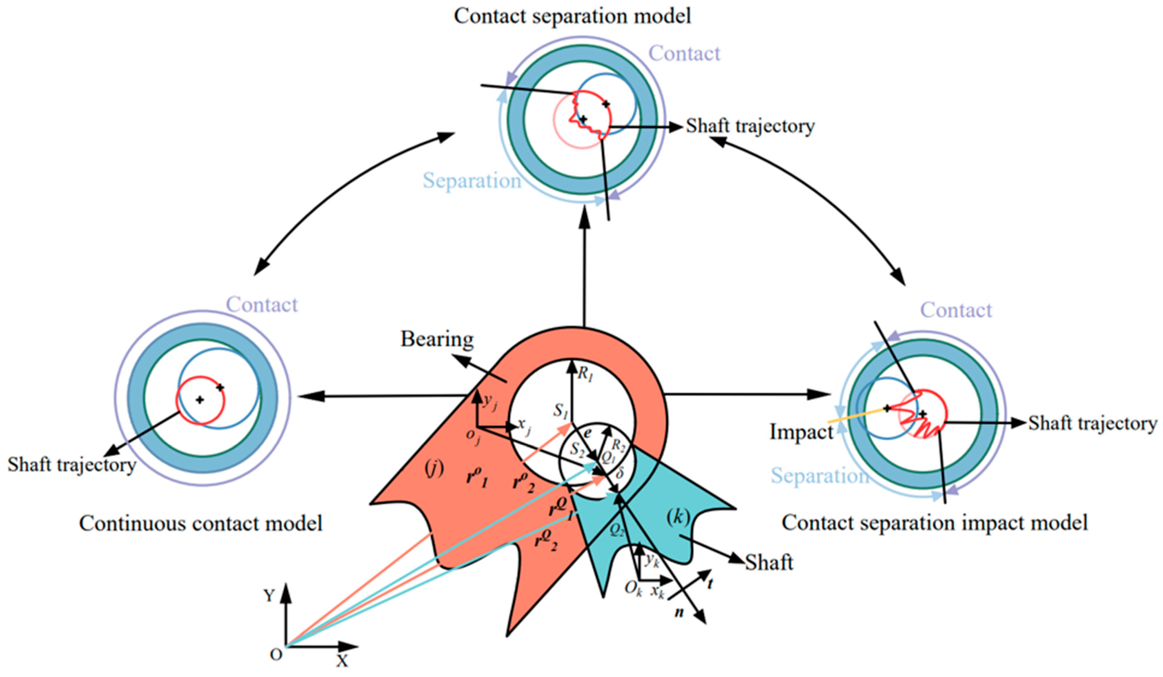
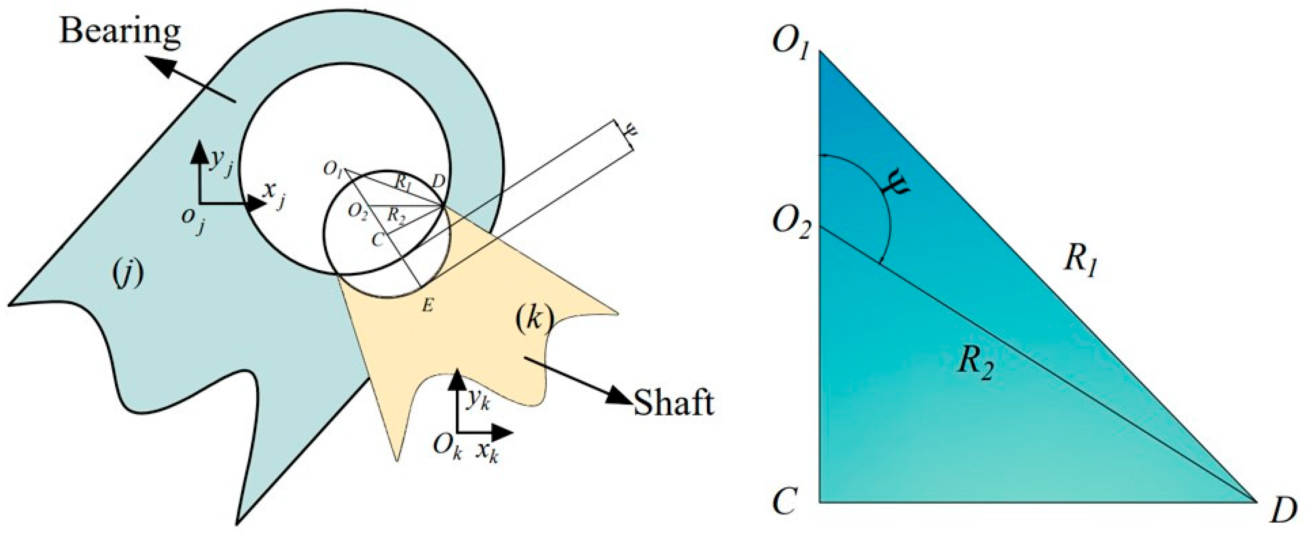
Building upon the Archard wear theory, a predictive model is formulated to quantify wear in revolute joints with clearance. The corresponding contact configuration and geometric relationships are depicted in
Figure 2.
As can be observed from the geometric relationship illustrated in the figure:
During collision in a revolute joint with clearance, the relative penetration depth is negligible compared to the radii of the shaft and bushing, and is defined as follows:
The actual contact area
can be expressed as:
where
denotes the axial contact width between the shaft and the bushing.
During practical operation, the components of a kinematic joint undergo multiple intermittent contacts and impacts within a constrained motion range. Accordingly, the total wear depth is considered the cumulative result of successive wear events.
Assuming equal wear depth for both the shaft and the bushing, their post-wear radii can be described as follows:
This model accounts for the wear phenomena occurring at kinematic joint clearances and facilitates the reconstruction of shaft and bearing surface geometries based on the computed wear depth. As wear accumulates, the resulting variations in component radii induce dynamic alterations in both penetration depth and impact forces. By continuously integrating the updated clearance parameters into the system’s dynamic equations, the time-evolving behavior of bionic medical devices—such as exoskeletons and rehabilitation robots—can be accurately captured under long-term operation and irregular wear conditions. This approach thus provides a theoretical foundation for evaluating system stability and predicting service life.
4. Modeling of the Mechanism’s Dynamics
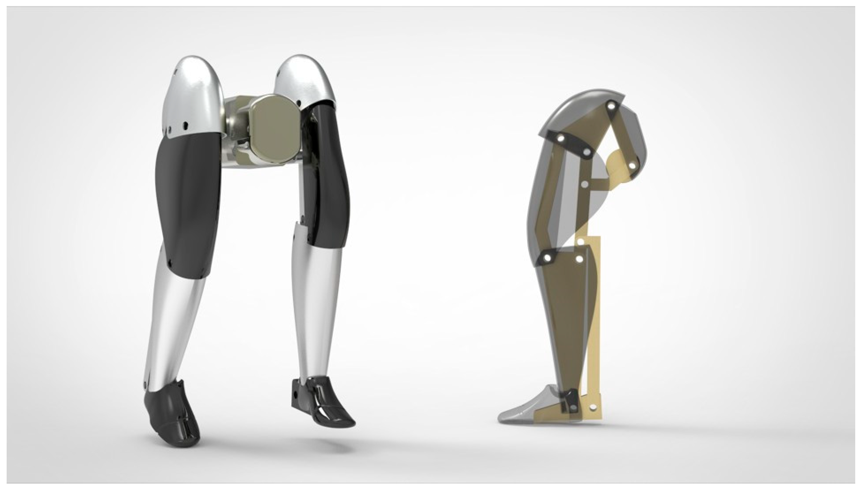
Figure 3 shows the three-dimensional model of the bionic humanoid leg mechanism with multiple revolute joint clearances.
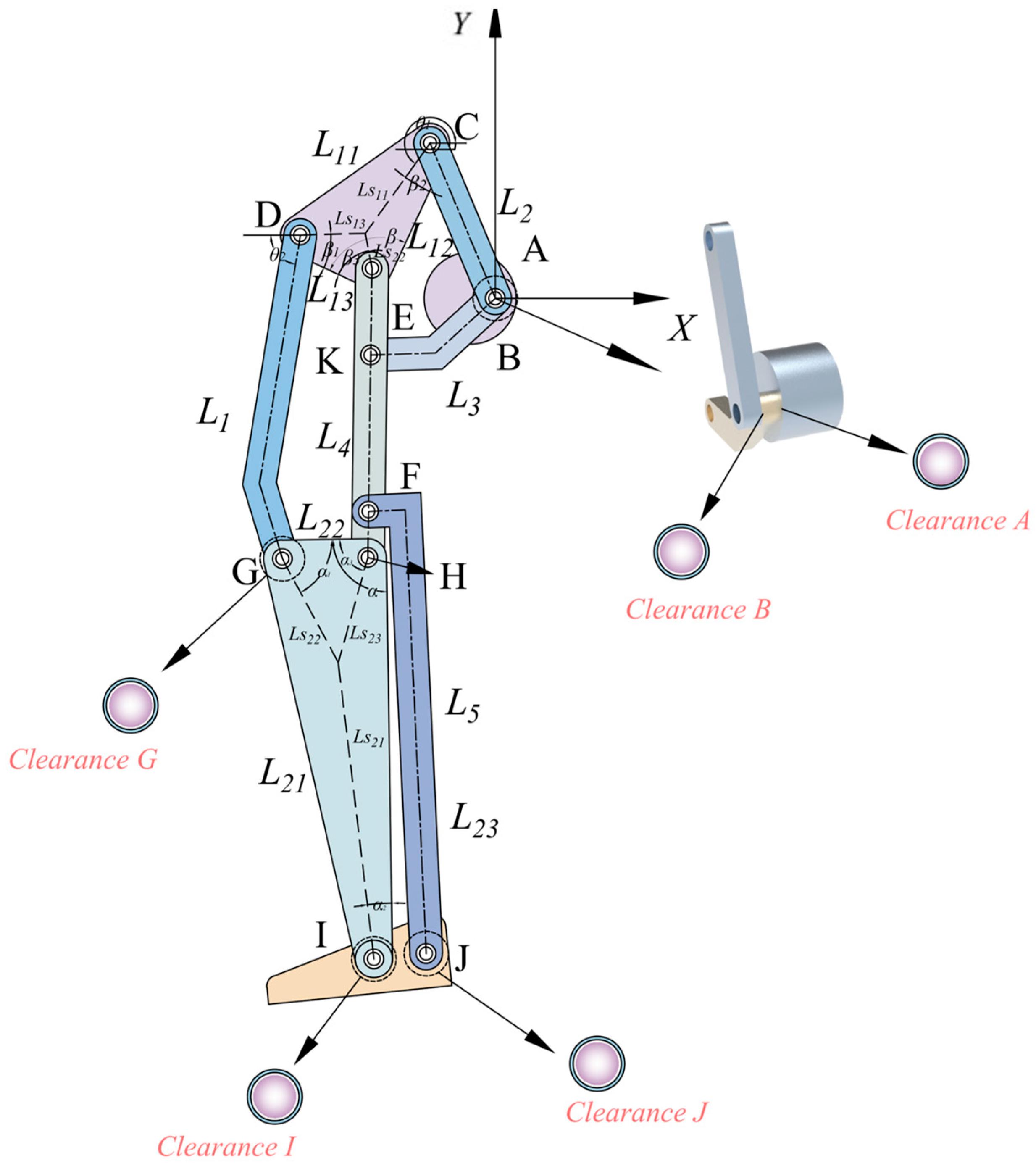
Figure 4 illustrates the coordinate schematic of the bionic humanoid leg mechanism featuring multiple revolute joint clearances. The generalized coordinates for each component are defined as follows:
where
and
represent the position components of component
in the X and Y directions of the system coordinate system, and
is the rotation angle of component
.
The first derivative of the generalized coordinates with respect to time gives the generalized velocity, which can be expressed as:
The time derivative of the generalized velocity yields the generalized acceleration, defined as follows:
The introduction of clearance in revolute joints modifies the motion direction and constraint relationships of the mechanism, leading to the elimination of two constraint equations. Specifically, the horizontal and vertical displacement constraints of the ideal revolute joints are no longer enforced. Accordingly, the displacement constraint equations accounting for revolute joint clearance are given as follows:
Taking the first derivative of the equation
with respect to time gives the velocity constraint equation.
where
q and
t represent the partial derivatives with respect to the generalized coordinates and time, respectively, and
is the Jacobian matrix.
,
.
The mechanism’s Jacobian matrix is given by:
Differentiating Equation (27) with respect to time yields the acceleration constraint equation:
where
,
.
The system’s dynamic equations can be expressed as:
where
is the generalized mass matrix,
is the generalized force of the system, and
is the Lagrange multiplier.
The generalized mass matrix is defined as follows:
where
represents the mass of each component, and
represents the moment of inertia of each component.
The system considers only rigid components and neglects elastic deformations of the mechanism. By combining Equations (27) and (28), the dynamic equations of the mechanism with revolute joint clearance can be obtained and expressed as:
To ensure the stability of the computational results, a stabilizing algorithm proposed by Baumgarte is introduced into the dynamic equations. This algorithm adds displacement and velocity constraints to the acceleration equations, which can be expressed as:
where
and
are correction parameters, both greater than 0. When they are equal, the equation converges quickly. And
[
42].
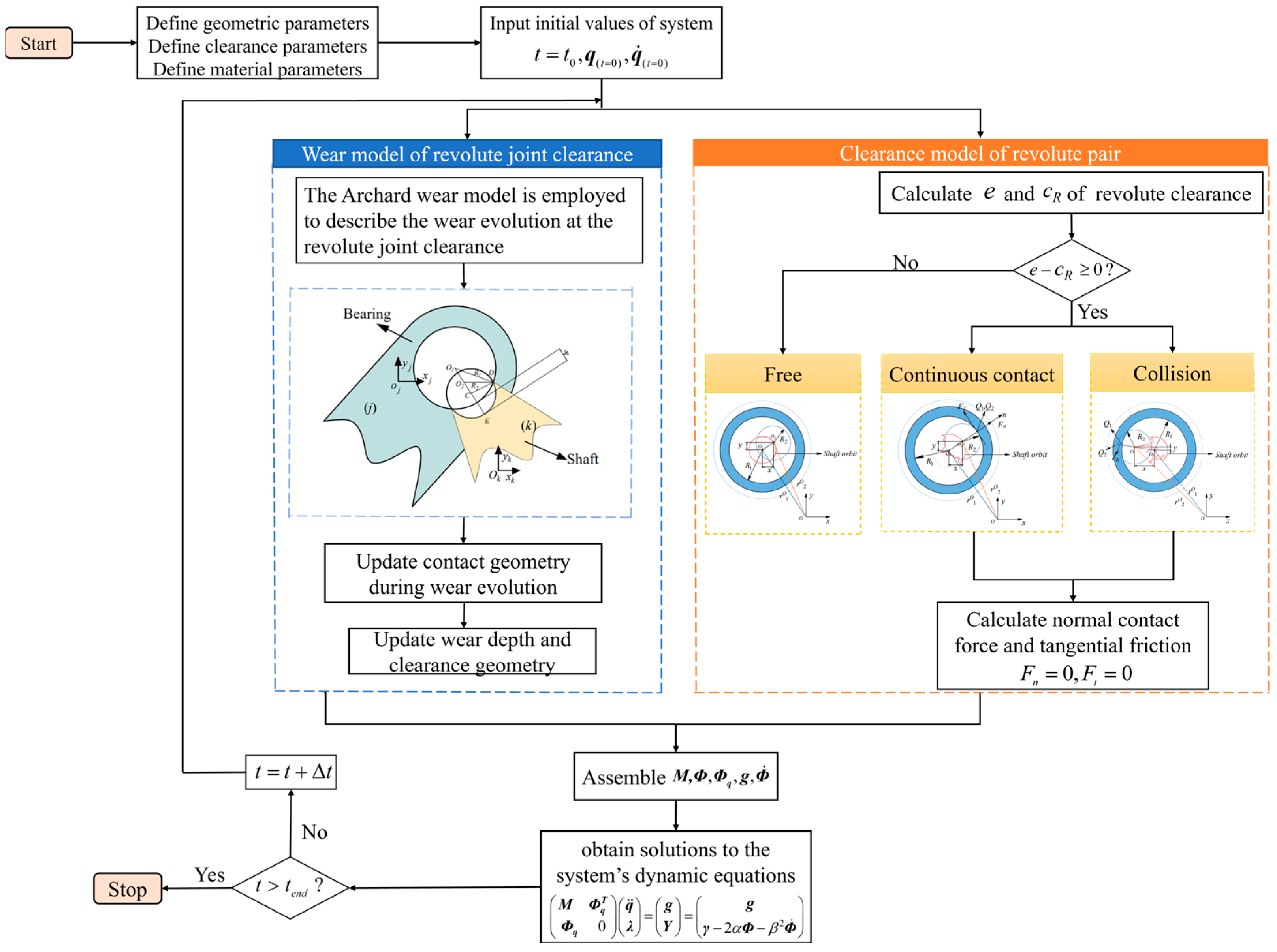
The overall modeling and solving procedure is illustrated in
Figure 5.
The structural parameters of the bionic humanoid leg mechanism are listed in
Table 1.
In the present study, both the shaft and the bushing are assumed to be made of structural steel. Accordingly, the material parameters used in the contact model are selected as representative values for steel, including a Young’s modulus of 207 GPa and a Poisson’s ratio of 0.29. The simulation parameters used in this study are listed in
Table 2.
6. Effect of Clearance Location on Dynamic Response and Wear in a Bionic Humanoid Leg Mechanism
In practical applications, in addition to clearance size, the specific location of clearances within the mechanism also has a significant influence on system performance. To further elucidate the mechanism of this factor, this chapter maintains the driving speed at 60 rpm and fixes the clearance size at 0.3 mm, while categorizing clearance locations into three critical regions: the hip joint, the tibiofemoral joint, and the foot [
43,
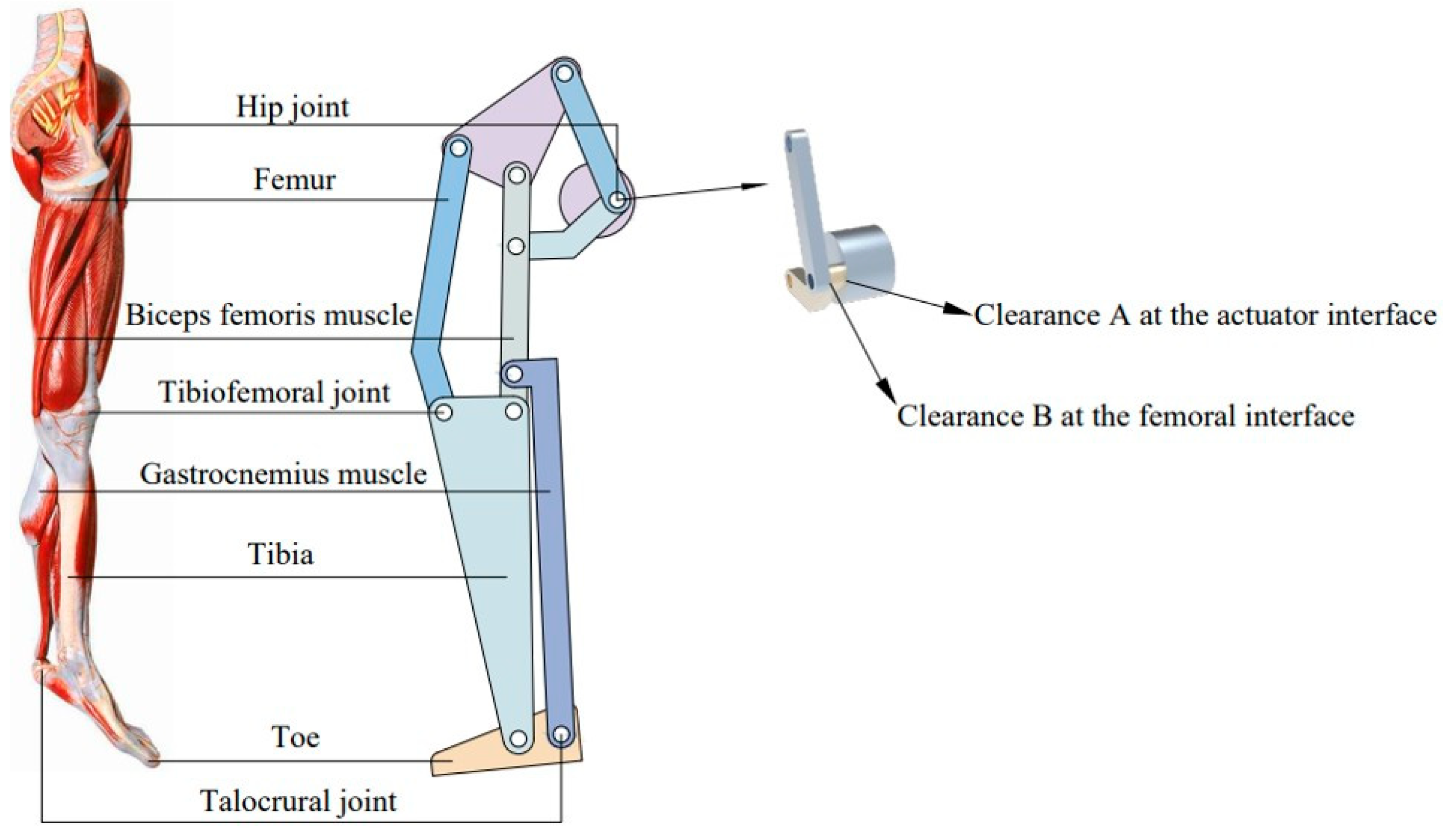
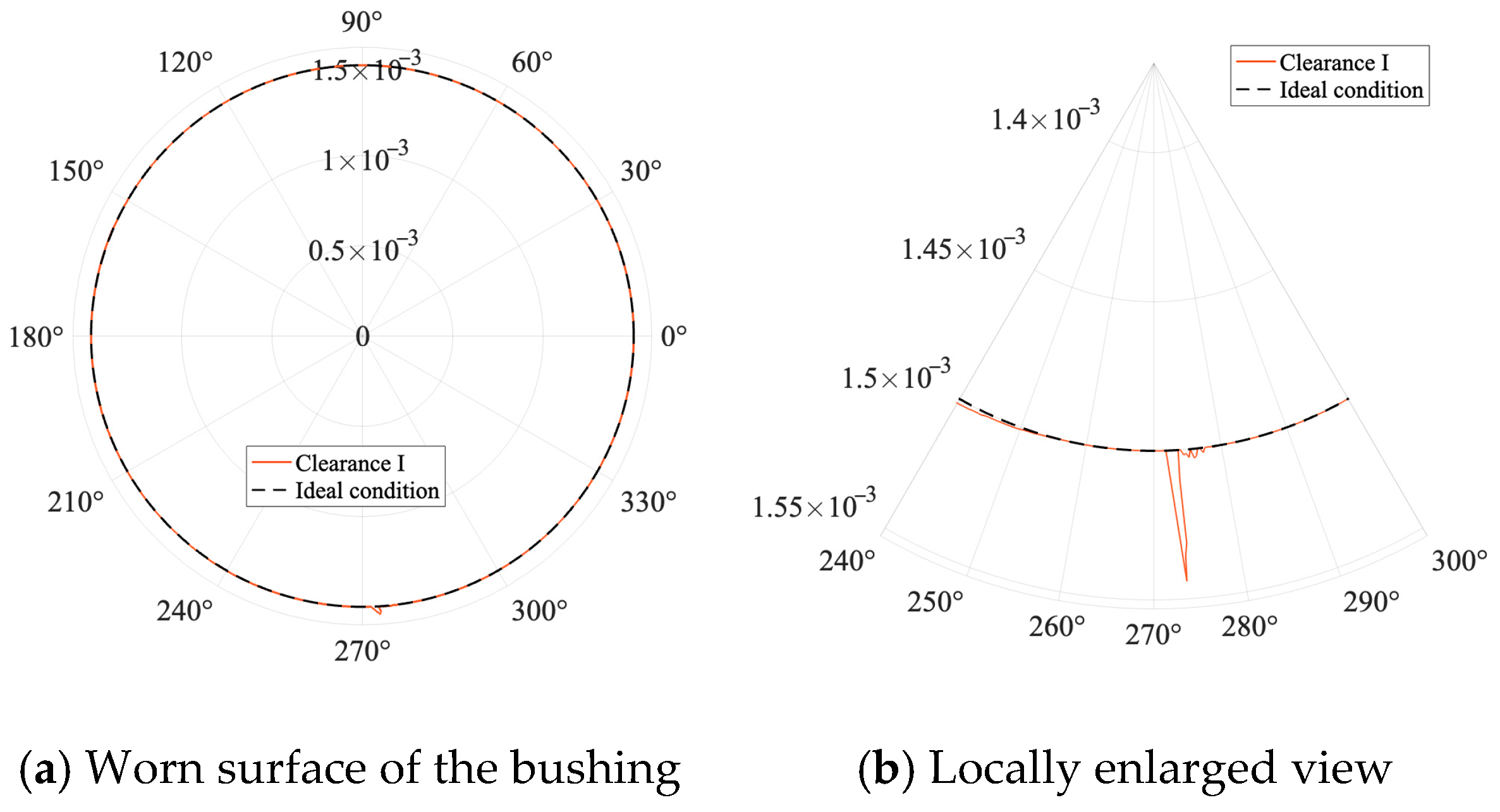
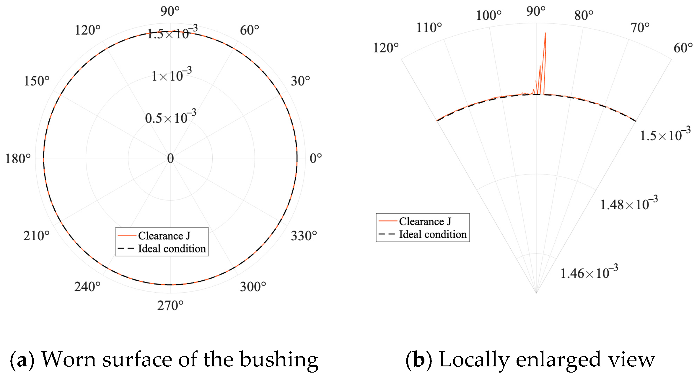
44]. At the hip joint, a composite clearance is considered, where clearance A connects to the driving unit and clearance B connects to the thigh. At the foot, clearance I represents the connection between the shank and the foot, while clearance J represents the connection between the shank tendon and the foot. By conducting comparative analyses of the dynamic response and wear characteristics under different clearance locations, this study aims to reveal the differentiated effects of clearance positions on dynamic response, local wear distribution, and overall stability. To facilitate observation, the radii of the bushing and the shaft are intentionally reduced to one-tenth in this study, enabling clearer visualization of the wear conditions.
The comparison between the bionic humanoid leg mechanism and the human lower limb is shown in
Figure 10.
6.1. Effect of Hip Joint Clearance on Dynamic Response of a Bionic Humanoid Leg Mechanism
The maximum errors of the dynamic response at the hip joint are summarized in
Table 3.
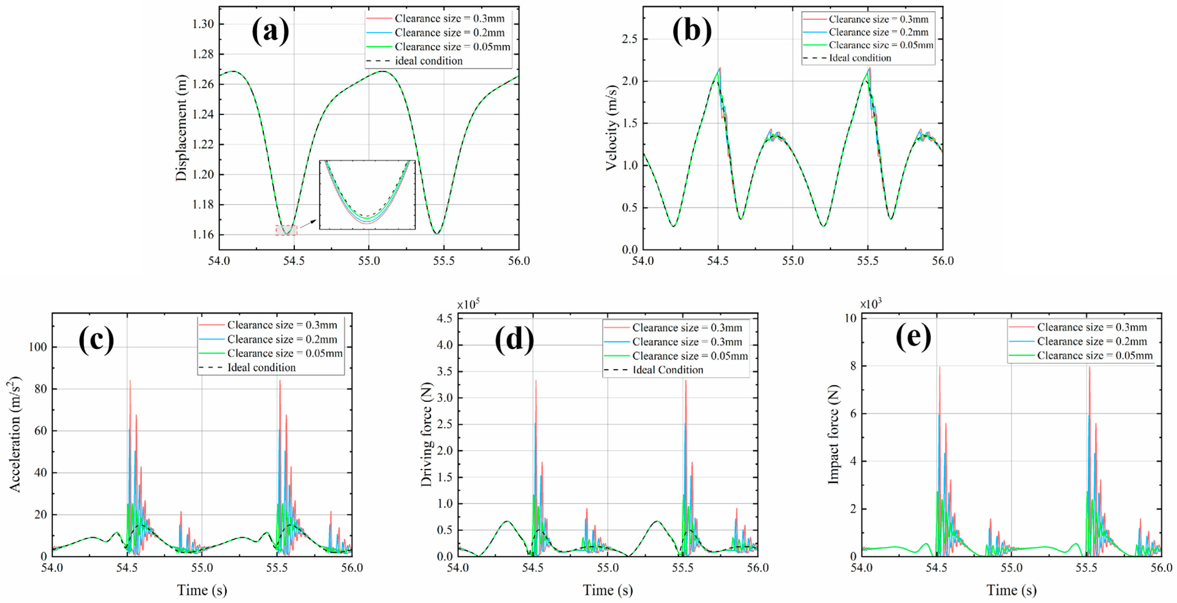
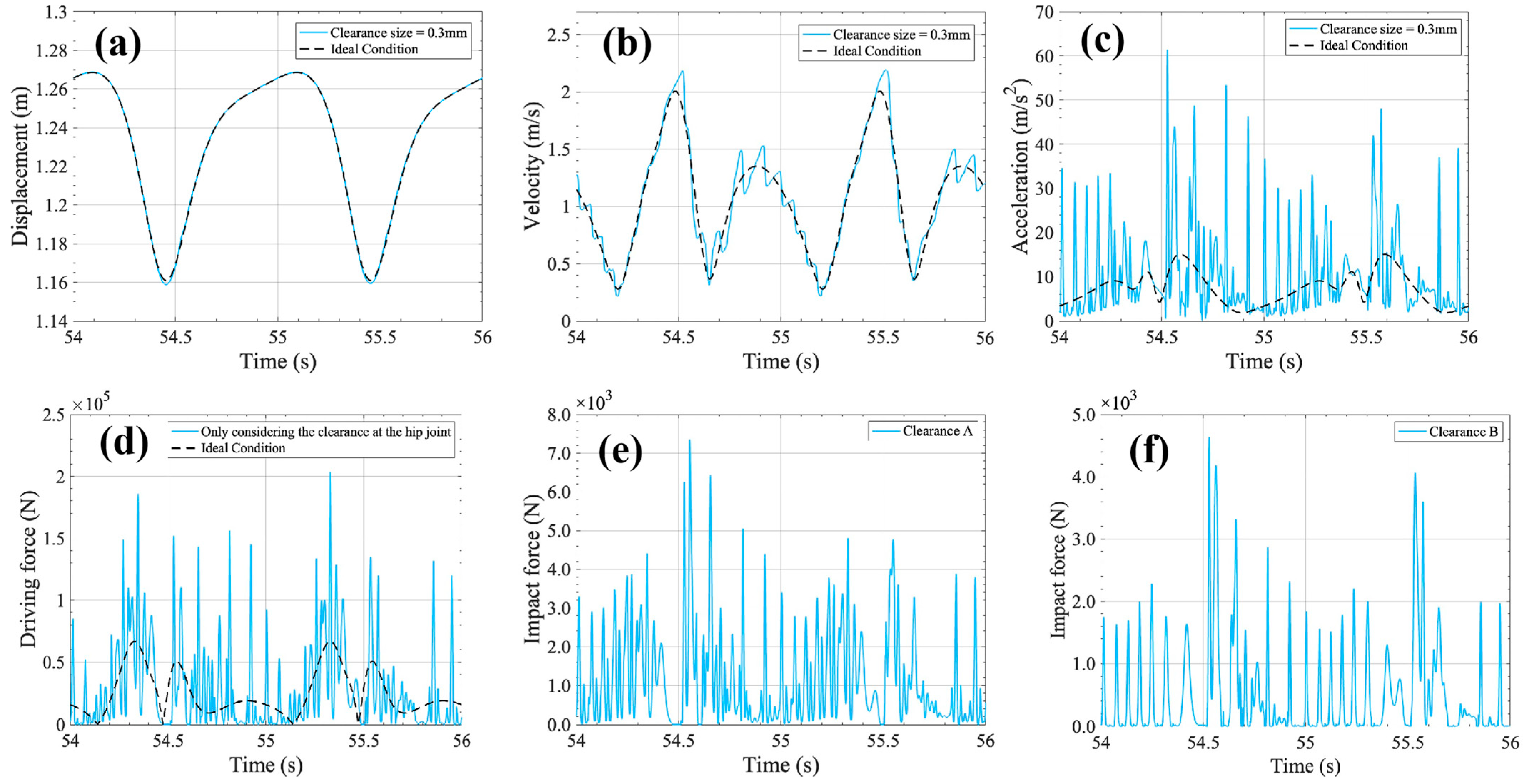
Clearances at the hip joint position exhibit significant influence on the dynamic response characteristics of the mechanism. As shown in
Figure 11a, with respect to the displacement response of the actuated component, although the presence of clearance introduces slight trajectory deviations, the overall motion trend remains stable, indicating that the mechanism possesses a certain level of buffering capacity against minor disturbances. However, in terms of velocity response in
Figure 11b, the velocity curves show multiple irregular fluctuations and pronounced spikes. Moreover, as depicted in
Figure 11c–f, the acceleration, driving force, and impact force curves all exhibit frequent discontinuities and high-frequency oscillations. These observations further reveal the destabilizing effect of hip joint clearances on the overall system dynamics. From the perspective of impact forces, both clearance A and clearance B lead to collisions between the shaft and the bushing. However, clearance A induces greater fluctuations. As shown in
Figure 11e, the impact force curve corresponding to clearance A displays dense oscillations, suggesting that clearances located at the driving end are more prone to excite non-periodic impacts within the structure and introduce disturbances into the system.
From the perspective of the overall structure, the clearance at the hip joint, being located close to the driving source, propagates disturbances downstream along the entire transmission chain, thereby posing greater challenges to the stable operation of the executing end. Such an upstream clearance may also reduce the overall structural rigidity, making the system more sensitive to external disturbances or dynamic operations. As a result, sharp peaks and fluctuations may appear in the velocity or acceleration signals, leading to a degradation of the mechanism’s stability.
In summary, the impact of hip joint clearance on the mechanism’s dynamic performance is strongly influenced by its structural location within the system. Comparatively, clearances positioned on the driving side impose greater negative effects on dynamic behavior. Therefore, these locations should receive prioritized consideration during the design phase to maintain response stability and ensure continuous motion transmission.
6.2. Effect of Hip Joint Clearance on Wear Characteristics of a Bionic Humanoid Leg Mechanism
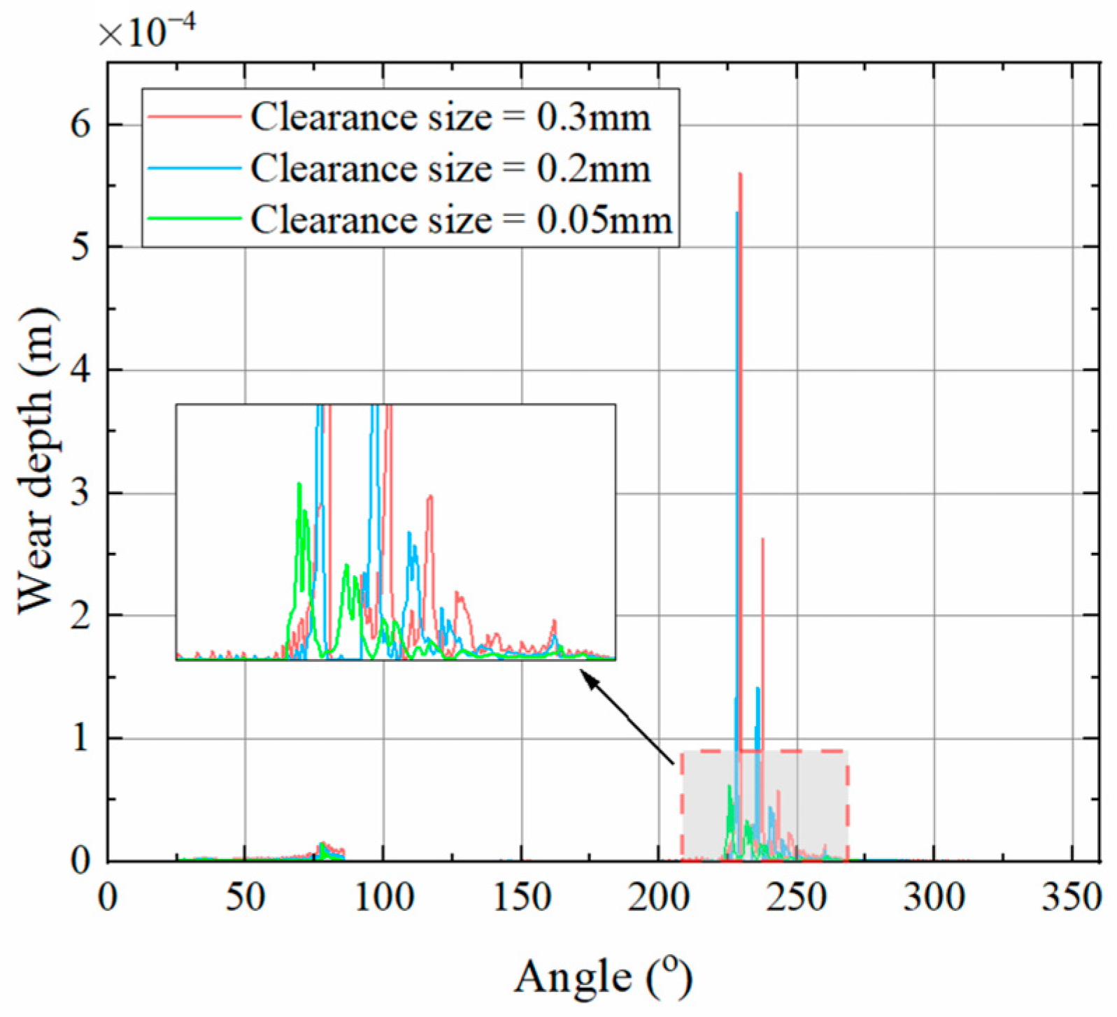
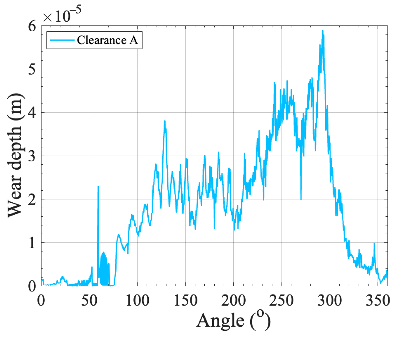
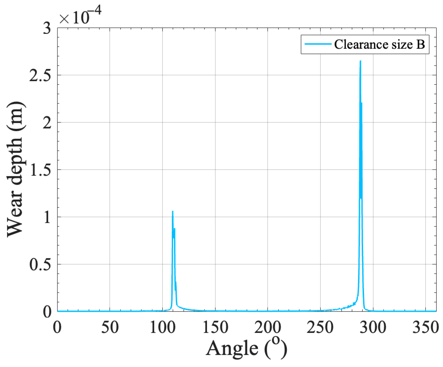
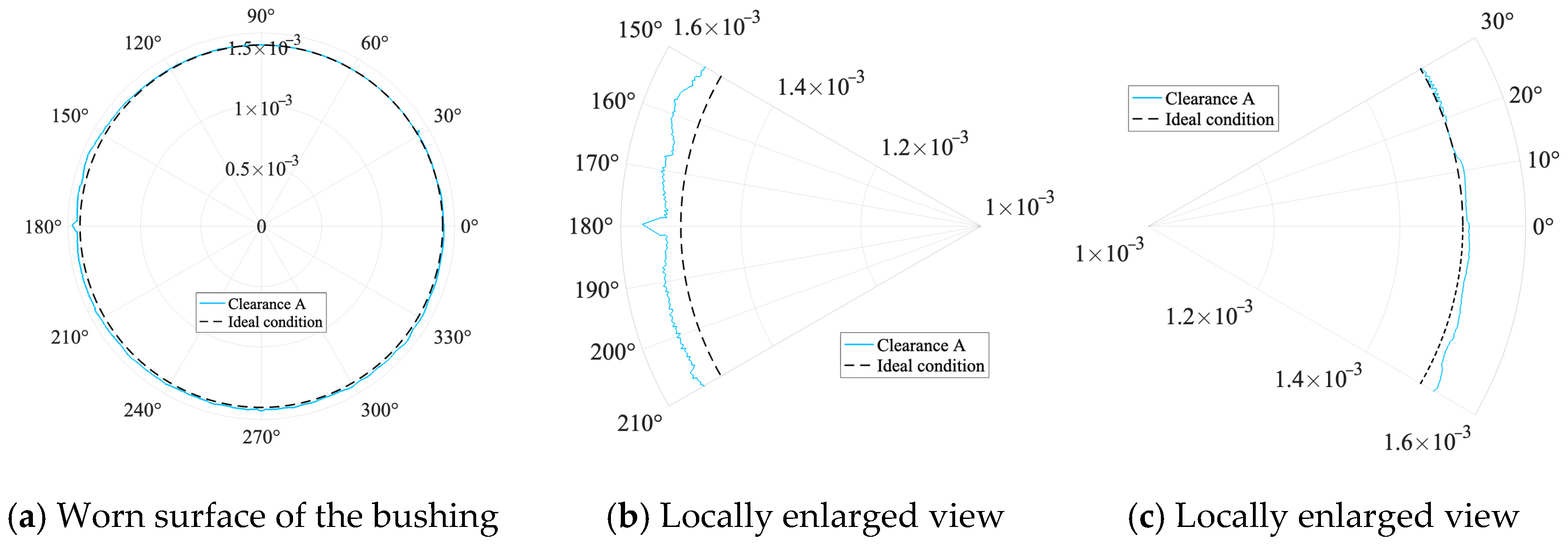
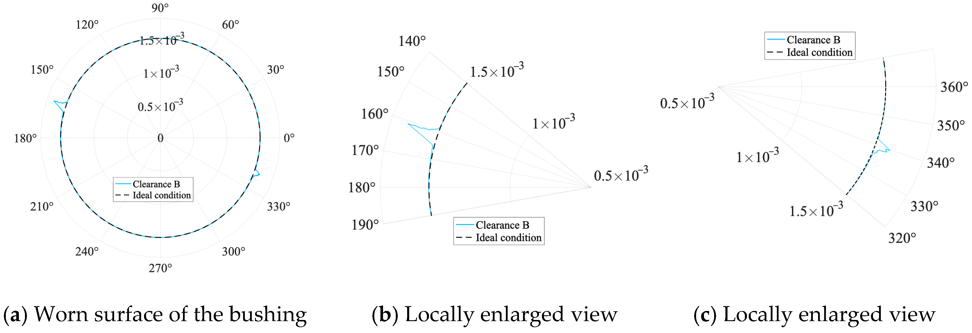
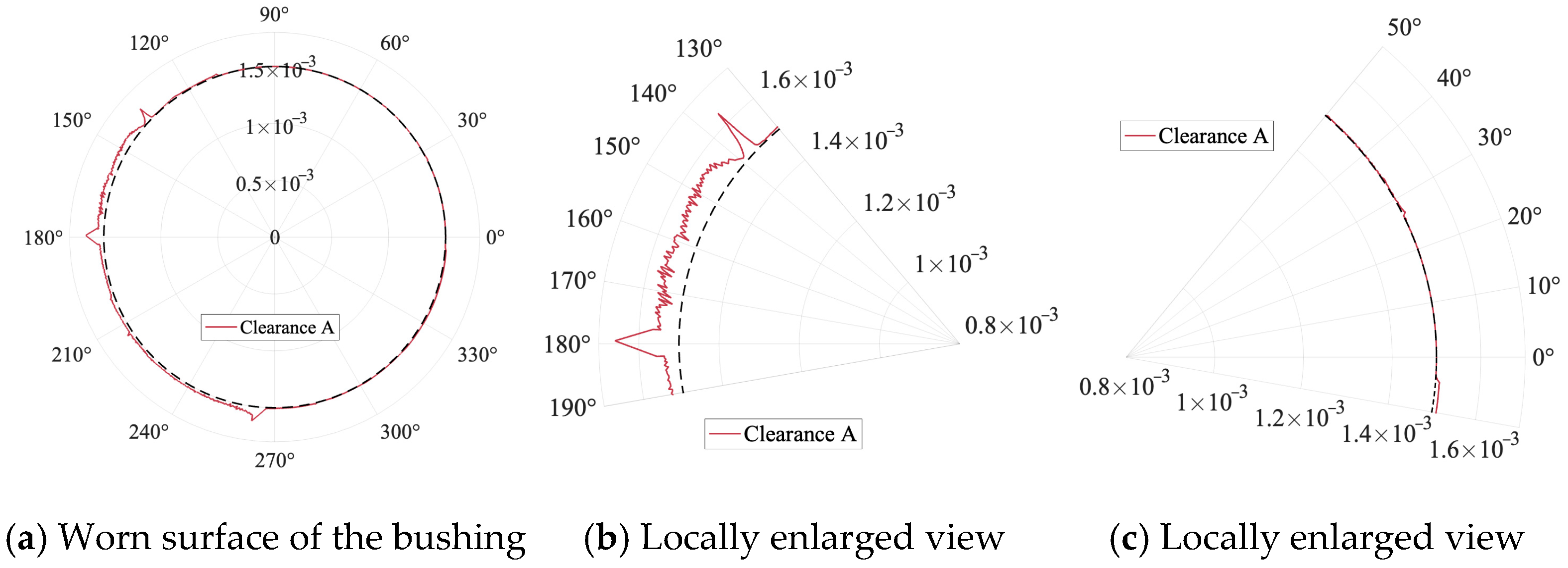
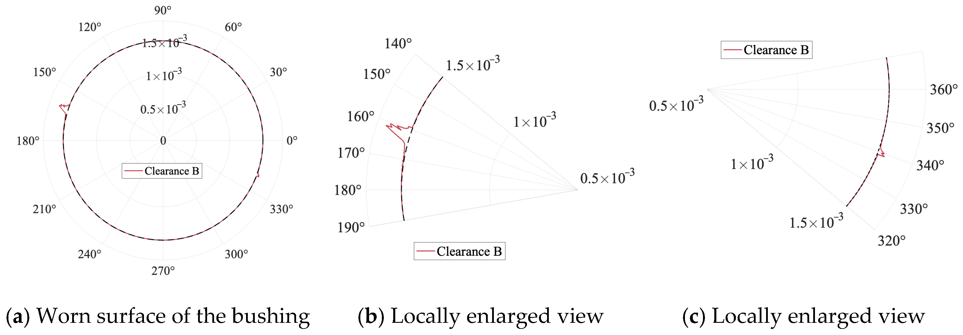
Under the condition where only the hip joint contains clearance, the wear behaviors induced by the driving-side connection (clearance A) and the execution-side connection (clearance B) exhibit distinct differences. Clearance A, being directly located at the driving end, is subjected to frequent non-continuous impacts excited by the input motion. Periodic reversals and angular velocity fluctuations lead to repeated contact–separation cycles between the shaft and the bushing, resulting in high-frequency and high-amplitude oscillations in the impact force curve. Notably, the peak impact forces observed at clearance A are significantly greater than those at clearance B. However, as shown in
Figure 12,
Figure 13,
Figure 14 and
Figure 15, despite the high contact frequency at clearance A, the corresponding wear intensity is not necessarily higher. On the contrary, the wear depth at this location remains relatively shallow, possibly due to the limited energy per individual impact. In contrast, clearance B exhibits significant wear accumulation within the shaft–bushing angular domain of [160°, 170°], indicating a localized wear-prone region. This suggests that the execution-side connection of such mechanisms requires particular attention in this angular range during design and maintenance.
Therefore, in structural design, stricter manufacturing and assembly accuracy constraints should be imposed on clearances located near the driving position, and greater emphasis should be placed on enhancing wear resistance at these locations.
6.3. Effect of Tibiofemoral Joint Clearance on Dynamic Response of a Bionic Humanoid Leg Mechanism
The maximum errors of the displacement, velocity, and acceleration responses under tibiofemoral joint clearance are listed in
Table 4.
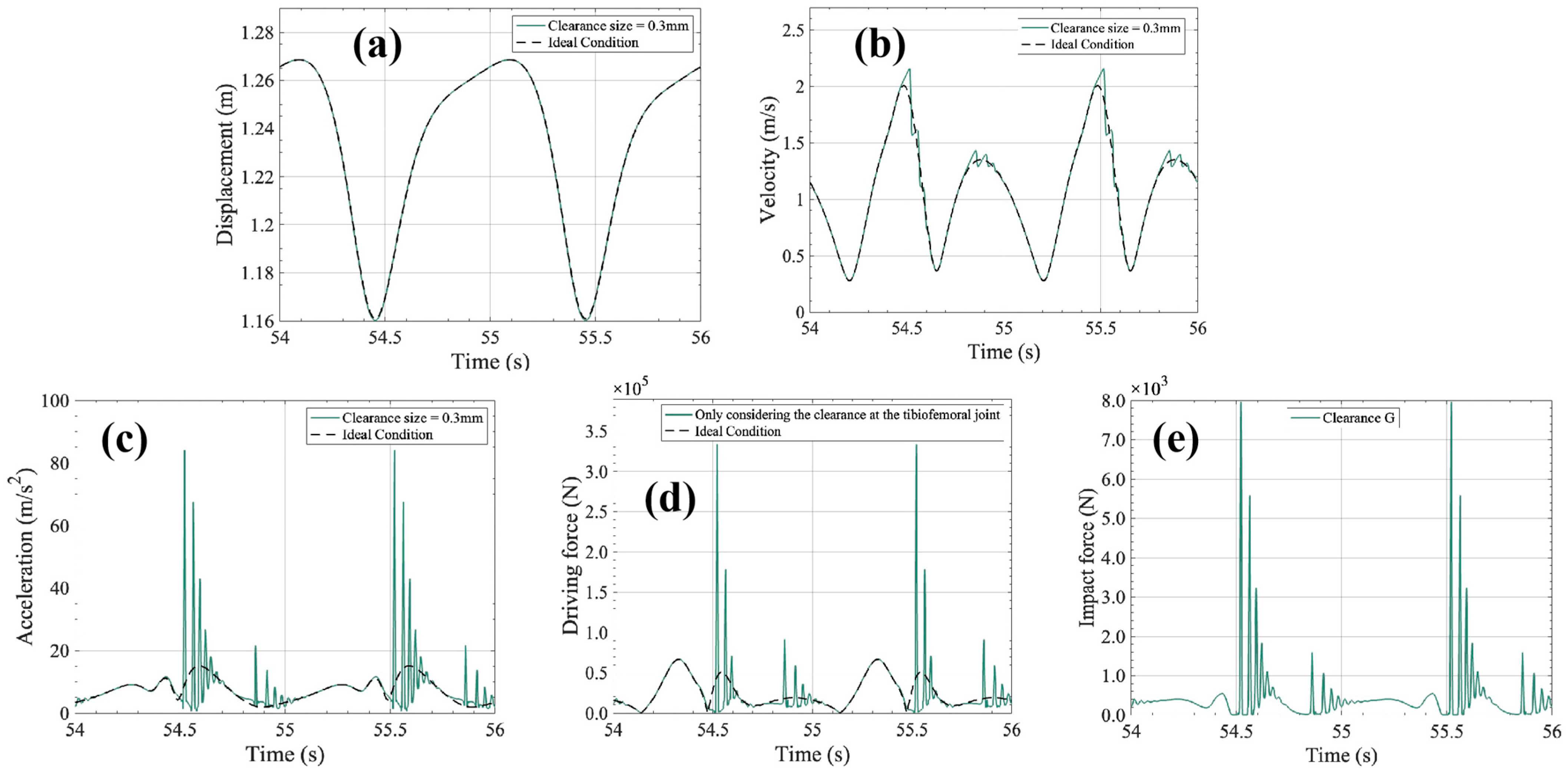
As shown in
Figure 16a, the clearance at the tibiofemoral joint induces slight disturbances in the displacement response of the actuated component. The overall displacement trend remains stable, with only minor trajectory deviations observed near the peak regions, indicating that the mid-link clearance has a relatively controllable influence on motion accuracy. However, in the velocity response, the system exhibits periodic fluctuations, and sharp spikes appear during certain intervals, suggesting that the effects induced by the clearance are gradually propagated to the execution end. The acceleration response further reveals high-frequency dynamic disturbances caused by the tibiofemoral joint clearance. The acceleration curves display multiple discontinuities and oscillations, with amplitude levels significantly higher than those in the ideal case, indicating that the mid-link clearance introduces disturbances of considerable intensity, which impair the stability of the terminal actuator. As shown in
Figure 16d, the driving force response is also affected by the tibiofemoral clearance, manifesting as high-frequency oscillations. The driving force curve exhibits abrupt changes across several cycles, with noticeably intensified local peaks. Furthermore, as depicted in
Figure 16e, the impact force response demonstrates a strong periodic contact behavior between the shaft and the bushing, accompanied by relatively high peak values. This indicates that although the tibiofemoral joint is neither at the driving side nor the terminal execution point, its clearance can still introduce significant disturbances along the transmission path.
The tibiofemoral joint clearance is located in the middle section of the structure, where its disturbances exhibit a buffering effect in both upstream and downstream transmission paths. Although such clearances are not at the most critical position of the mechanism, they should still be taken into account in the design process.
In summary, although the tibiofemoral joint clearance does not exert direct influence from the driving source or the terminal components, its structural position within the mechanism renders it an important factor affecting the dynamic response of the system.
6.4. Effect of Tibiofemoral Joint Clearance on Wear Characteristics of a Bionic Humanoid Leg Mechanism
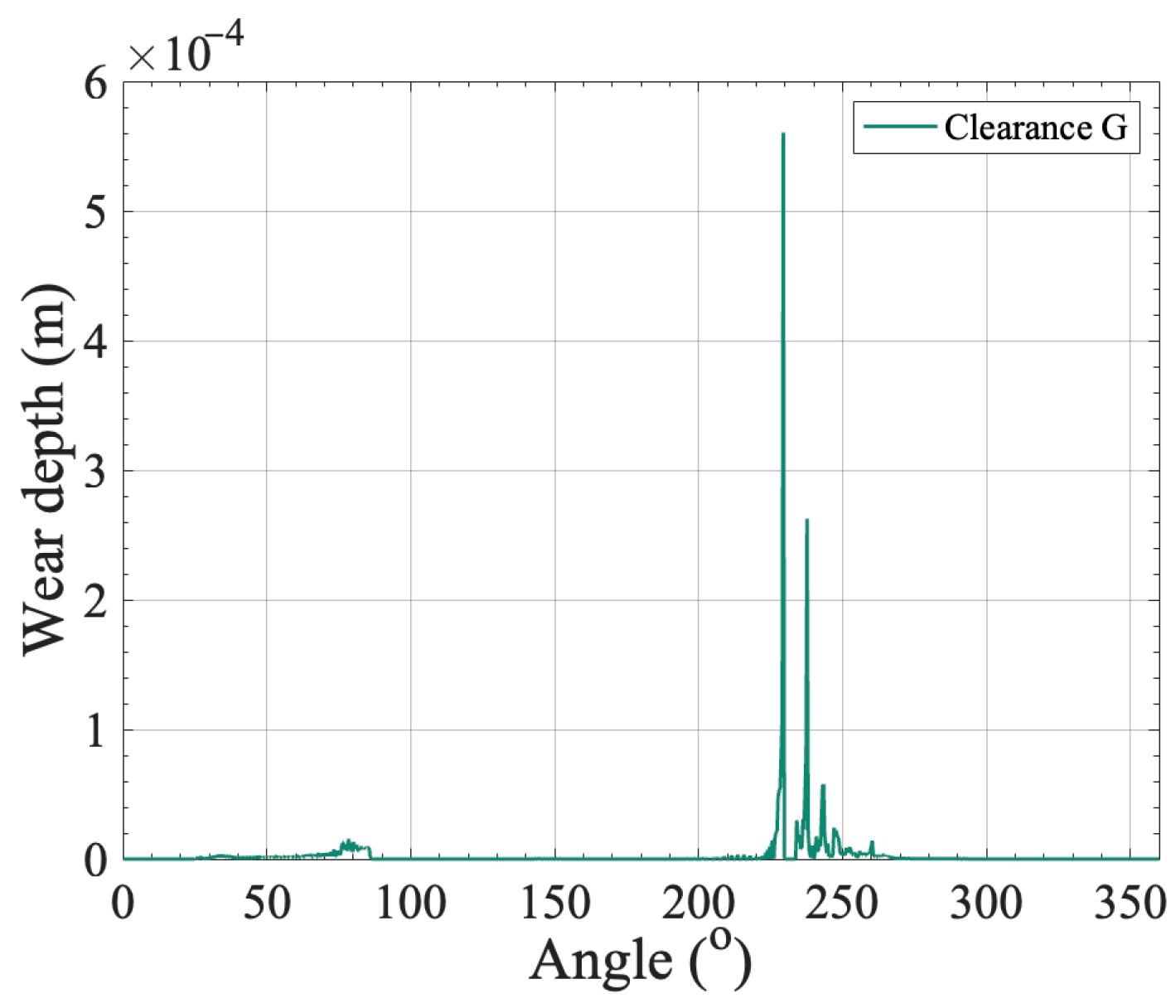
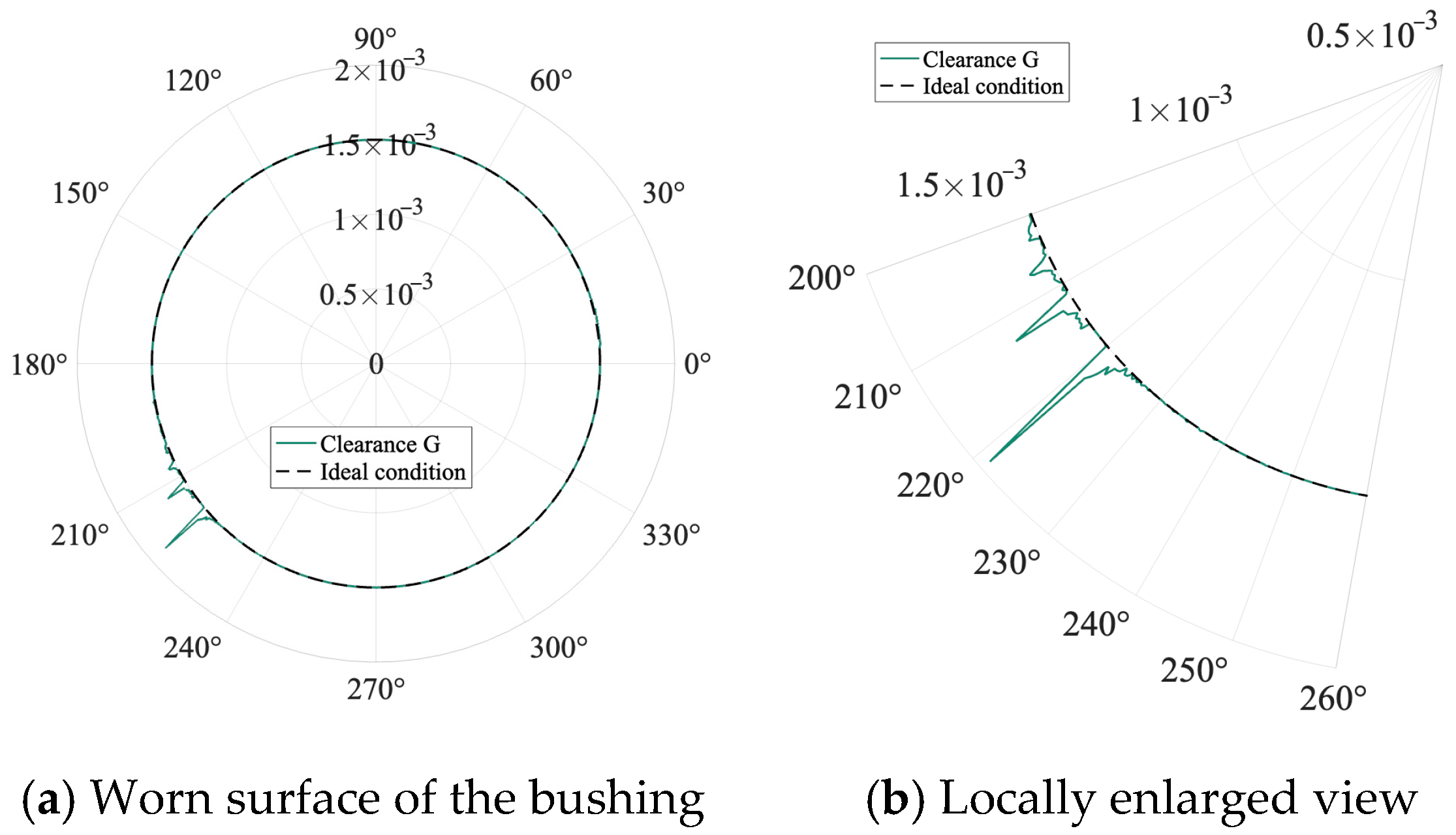
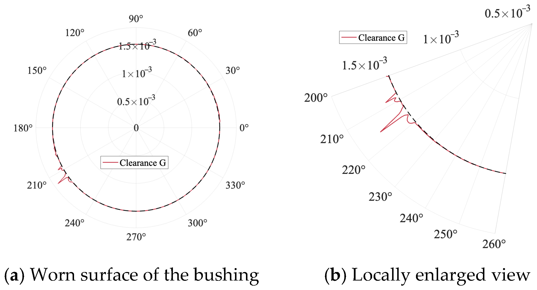
The wear depth distribution at clearance G under tibiofemoral joint clearance is shown in
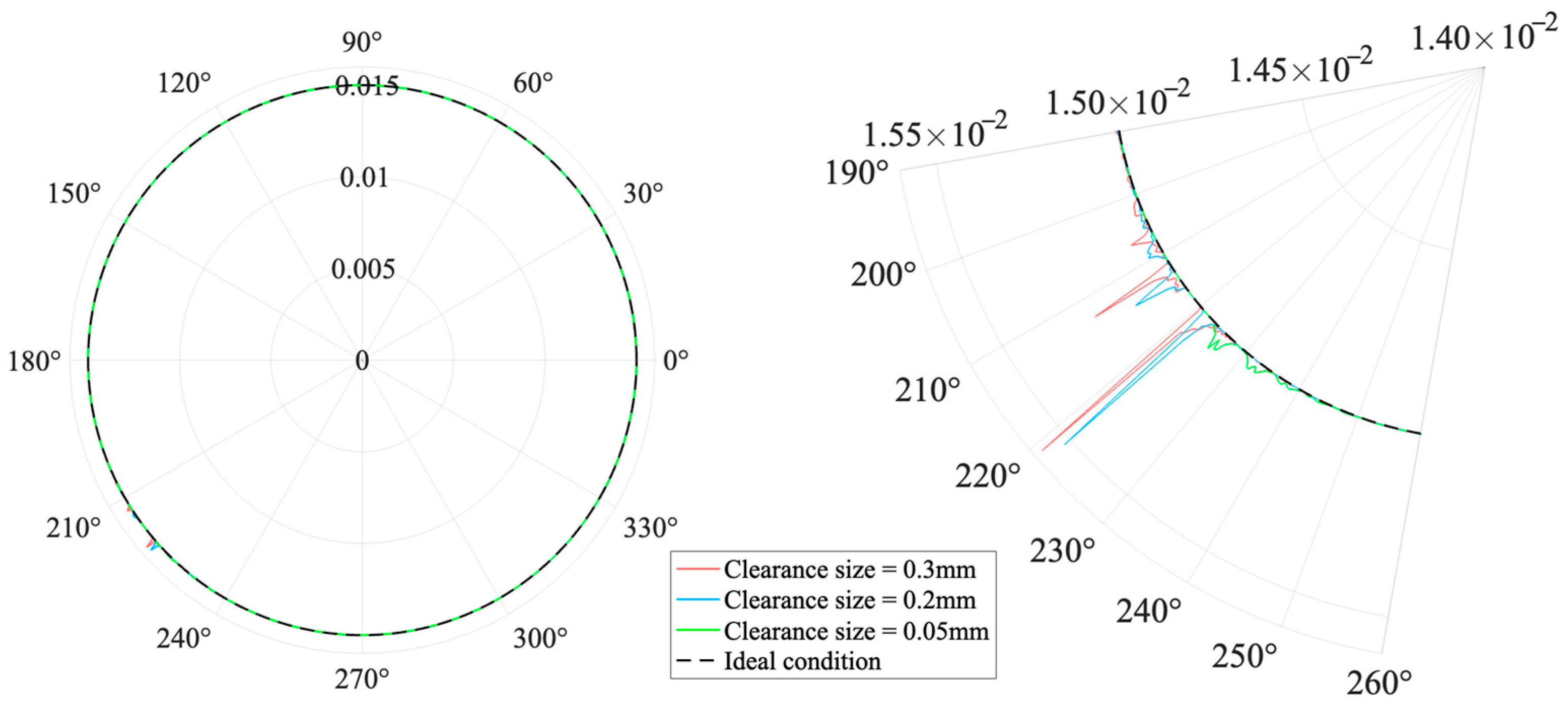
Figure 17. Due to the periodic oscillations observed in the impact force at the clearance location—with stable amplitude and sustained duration—frequent and regular contact–separation behavior between the shaft and the bushing can be inferred. Such persistent collisions cause the contact surface at the clearance to be subjected to long-term repetitive impacts. The resulting wear further impairs the precision control of the downstream foot actuator and compromises the overall trajectory consistency and dynamic stability of the system. In addition, since the tibiofemoral joint is located at the middle segment of the mechanism, the clearance at this location typically exhibits a dual role of “buffering” and “transmitting.” On one hand, it can partially absorb the sharp dynamic shocks transmitted from the driving source, thus serving as a damping buffer. On the other hand, collisions generated by the shaft–bushing interactions at this joint may also propagate backward as low-intensity disturbances, potentially becoming a secondary source of dynamic instability in the system. The schematic diagram of bushing wear at clearance G and the corresponding locally enlarged view are shown in
Figure 18.
In summary, although the tibiofemoral joint clearance does not exhibit the same level of direct destructiveness as the driving-end clearance, it plays a multifaceted role in wear behavior—acting as a latent initiator, a gradual propagator, and a transmission bridge. Therefore, it should be given sufficient attention in the design of long-term system stability. Proper control of its clearance tolerance and fit configuration can effectively mitigate the potential adverse effects of non-ideal contact on the overall service life of the mechanism.
6.5. Effect of Foot Joint Clearance on Dynamic Response of a Bionic Humanoid Leg Mechanism
The maximum errors of the displacement, velocity, and acceleration responses under foot joint clearances are listed in
Table 5.
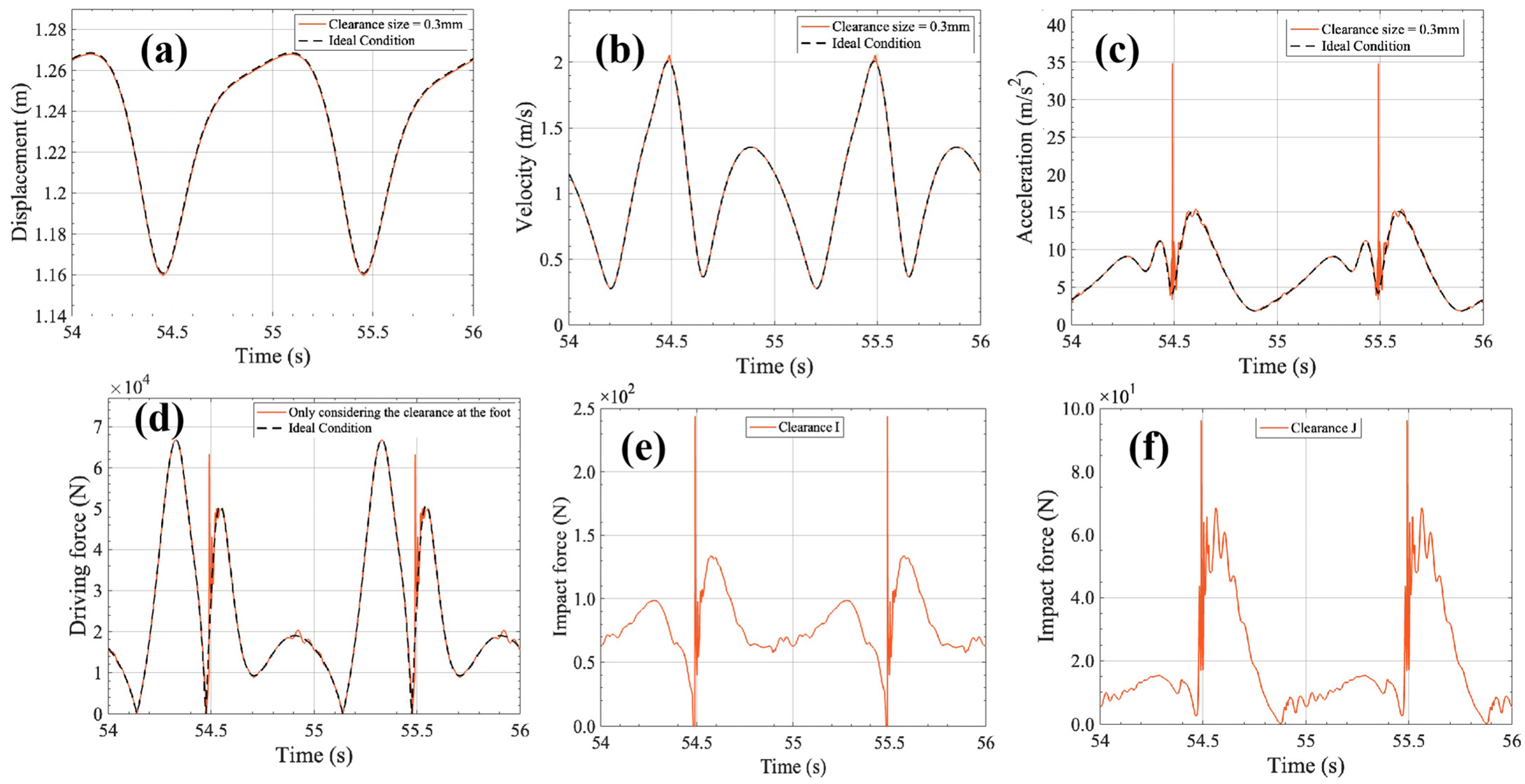
As shown in
Figure 19a,b, both the displacement and velocity responses exhibit slight deviations near the peak regions, indicating that the clearance at the foot has a relatively limited effect on the position and velocity accuracy of the terminal component.
Figure 19c–f illustrate the acceleration and driving force responses. Although their vibration frequencies and peak amplitudes are not as significant as those observed in the previously analyzed cases, noticeable differences still exist when compared to the ideal condition. Both responses exhibit peak fluctuations and localized oscillations near the midpoints of each motion cycle. The impact force response further reveals the collision characteristics induced by the foot-end clearance. As shown in
Figure 19f, the impact force curve corresponding to clearance J displays a higher frequency, denser oscillations, and relatively larger amplitudes. This suggests that the connection clearance at the lower leg tendon is more prone to rapid contact–separation events, generating instantaneous impacts that disturb the dynamic behavior of the terminal structure. In contrast, clearance I exhibits fewer collision events with lower magnitudes, indicating that the contact behavior at this location is weaker and its interference with the system is comparatively minor.
Since the terminal clearance directly acts on the executing component, it is highly prone to inducing local dynamic instability, thereby challenging the overall stability of the mechanism. Clearance J, which simulates the tendon connection, plays a special role in regulating the stability of the executing component. Compared with clearance I, its collision behavior is more complex, leading to a more pronounced impact on the output accuracy and steady-state performance of the system.
In summary, although the revolute joint clearances at different positions of the foot exert less influence on the dynamic performance of the mechanism compared with those located near the driving end or in the mid-structure, their proximity to the executing component makes the system more susceptible to instability even under low-intensity disturbances. In particular, the clearance simulating the tendon connection is more sensitive to system perturbations, and thus requires greater attention in design and control to enhance the continuity and accuracy of the dynamic performance of the executing component.
6.6. Effect of Foot Joint Clearance on Wear Characteristics of a Bionic Humanoid Leg Mechanism
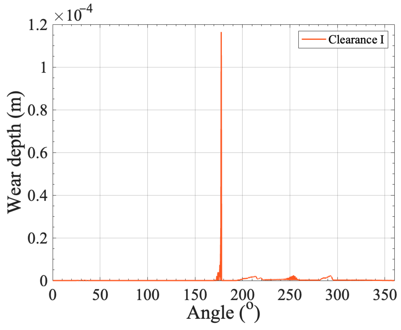
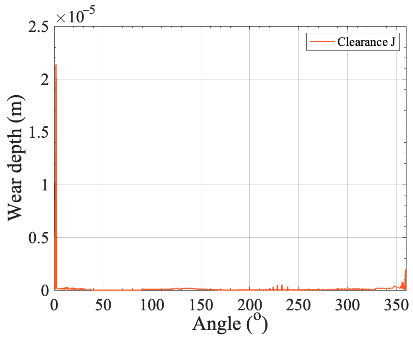
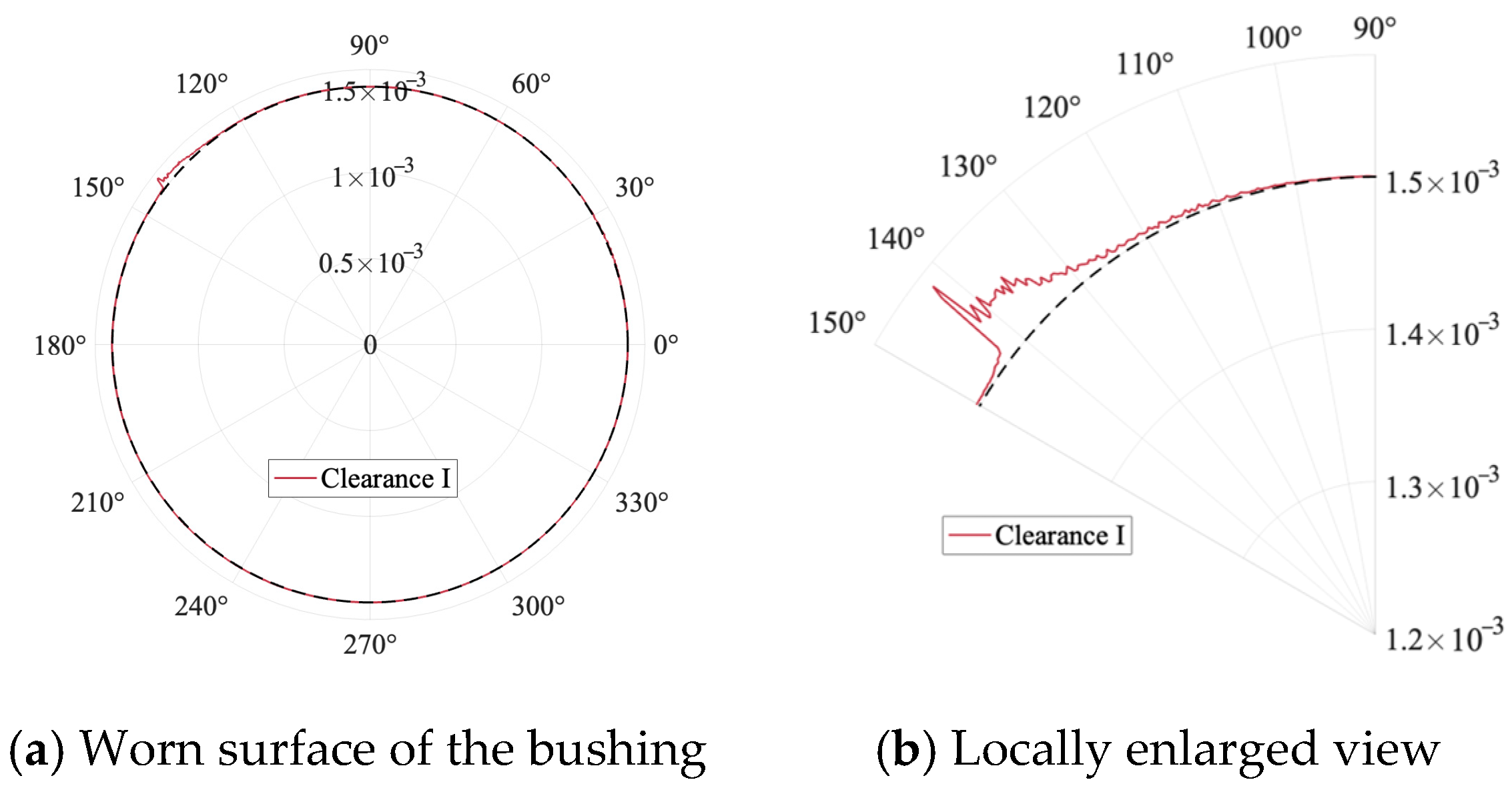
When only foot clearances are introduced, both clearance locations exhibit noticeable wear characteristics. However, due to their different positions at the terminal end of the mechanism, asymmetries in dynamic transmission paths and inertial effects lead to distinct wear behaviors. As illustrated in
Figure 20,
Figure 21,
Figure 22 and
Figure 23, the wear severity at clearance J is significantly greater than that at clearance I, and the corresponding wear concentration regions differ markedly. Clearance J, which simulates the lower leg tendon connection, primarily functions to maintain the stability of the terminal structure. Positioned at the distal end of the motion chain and subjected to downstream inertial effects, impacts occurring at this location tend to be further amplified. Consequently, the wear behavior at clearance J reveals a more complex wear mechanism.
From the perspective of system structural function, although the foot clearance is distant from the driving source, it directly affects the output position of the executing component, and its wear behavior exhibits a highly localized characteristic. Once non-ideal contact occurs at this location, the stability of the mechanism can be easily compromised. Therefore, in practical design and assembly, special attention should be paid to clearance J, which functions to maintain stability. It is essential to appropriately reduce the manufacturing and installation tolerances at this position and to optimize the shaft–bushing contact pair, thereby mitigating wear induced by repeated impacts. Such measures are crucial for ensuring the stable operation and service life of the mechanism.
Overall, the comparative results indicate that clearance size mainly governs the severity of contact-impact nonlinearity, while clearance location determines how the disturbance is transmitted through the mechanism. In addition, the shaft–bushing contact geometry influences the local concentration of wear and the periodicity of impact responses. Therefore, the system behavior is jointly controlled by clearance magnitude, structural position, and local contact configuration.
7. Effect of Multi-Location Joint Clearances on Dynamic Response, Wear Characteristics, and Chaotic Behavior of a Bionic Humanoid Leg Mechanism
In the analysis of single-location clearances, each clearance has been shown to exhibit its own distinctive disturbance patterns and influence range. However, during actual operation, multiple revolute joint clearances often coexist, and their synergistic effects may induce coupled excitations and path superposition in the dynamic response of the mechanism. In this section, five clearances located at the hip joint, the tibiofemoral joint, and the foot are considered simultaneously, with the clearance size set to 0.3 mm and the driving speed fixed at 60 rpm, in order to investigate the influence of clearances on the overall dynamic performance of the system under realistic conditions. This analysis not only further improves the theoretical framework proposed in this study but also enhances its universality and application value for other mechanisms.
7.1. Effect of Multi-Location Joint Clearances on the Dynamic Response of a Bionic Humanoid Leg Mechanism
The maximum errors of the displacement, velocity, and acceleration responses under multi-location joint clearances are listed in
Table 6.
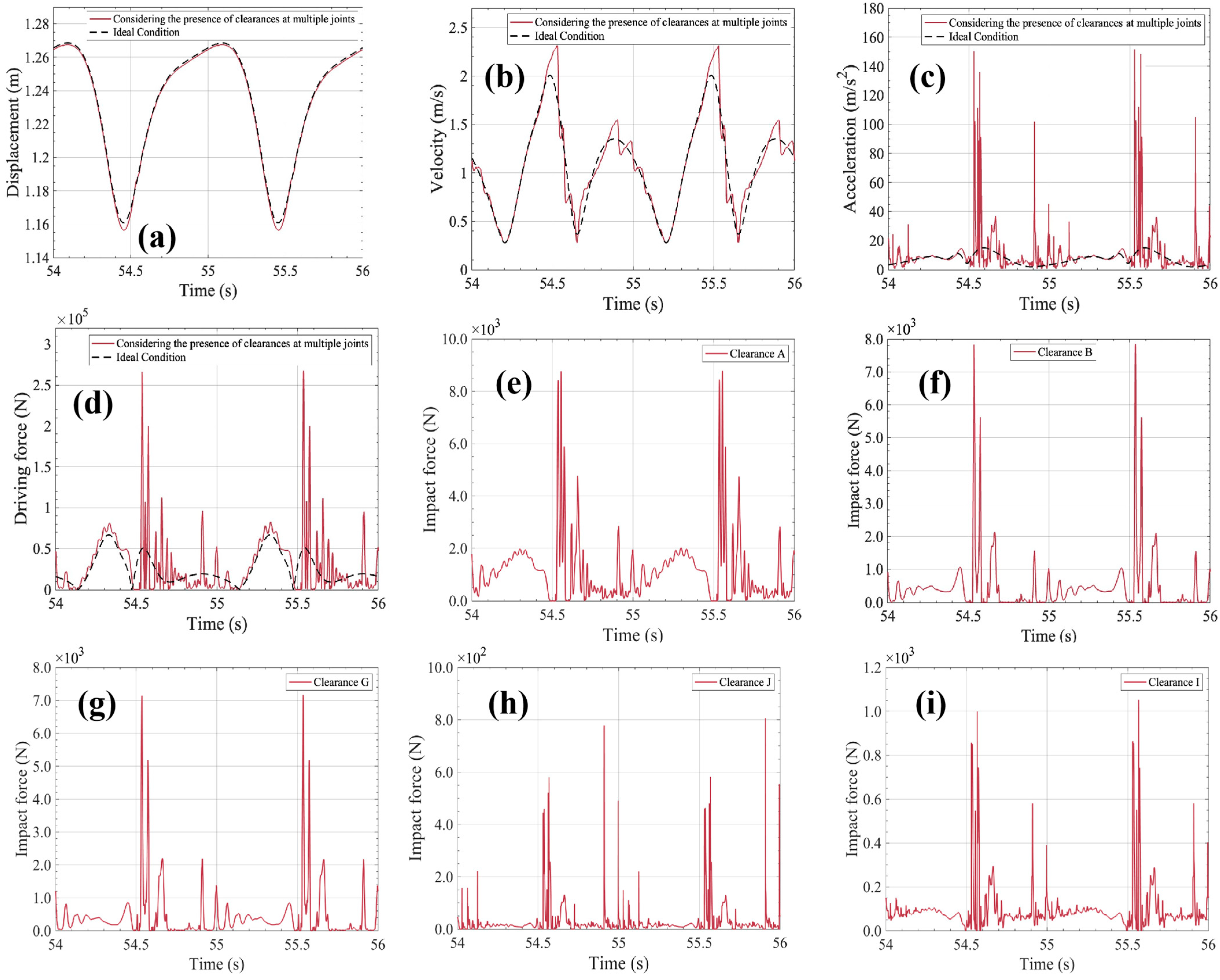
As shown in
Figure 24a, the presence of multiple clearances significantly amplifies the displacement disturbances of the actuated component. Compared to single-clearance cases, the displacement response exhibits greater deviations, indicating that the motion accuracy of the mechanism is more severely affected by multi-source disturbances.
Figure 24b–d present the velocity and acceleration responses. The velocity curve displays enhanced high-frequency components, while the acceleration response shows multiple peaks and abrupt numerical variations, suggesting that the system is subjected to non-continuous excitation and its dynamic stability is compromised. The driving force response further reveals the influence of multiple clearances. As illustrated in
Figure 24c, in contrast to systems with a single clearance, the driving force curve under multiple-clearance conditions exhibits intensified oscillations. The linearity of energy transmission is disrupted, and the system demonstrates clear dynamic lag and overshoot behavior within each operation cycle.
Under the condition of multiple clearances coexisting at different locations, the system response is not a linear superposition. The driving-end clearances (clearances A and B) influence the output characteristics, the mid-structure clearance (clearance G) modulates the disturbance transmission path, and the terminal clearances (clearances I and J) directly affect the response accuracy of the executing end. The synergistic action of these three types of disturbance sources thus imposes greater challenges on the stability and service life of the mechanism.
In summary, the coexistence of multiple clearances at different locations significantly alters the dynamic response mechanism of the bionic humanoid mechanical leg. It not only induces stronger impacts and oscillations but also disrupts the dynamic consistency of the structure. Compared with the case of a single clearance, the resulting systemic disturbances are more difficult to mitigate through local optimization alone, requiring comprehensive strategies in overall design, clearance control, and manufacturing–assembly processes.
7.2. Effect of Multi-Location Joint Clearances on Wear Characteristics of a Bionic Humanoid Leg Mechanism
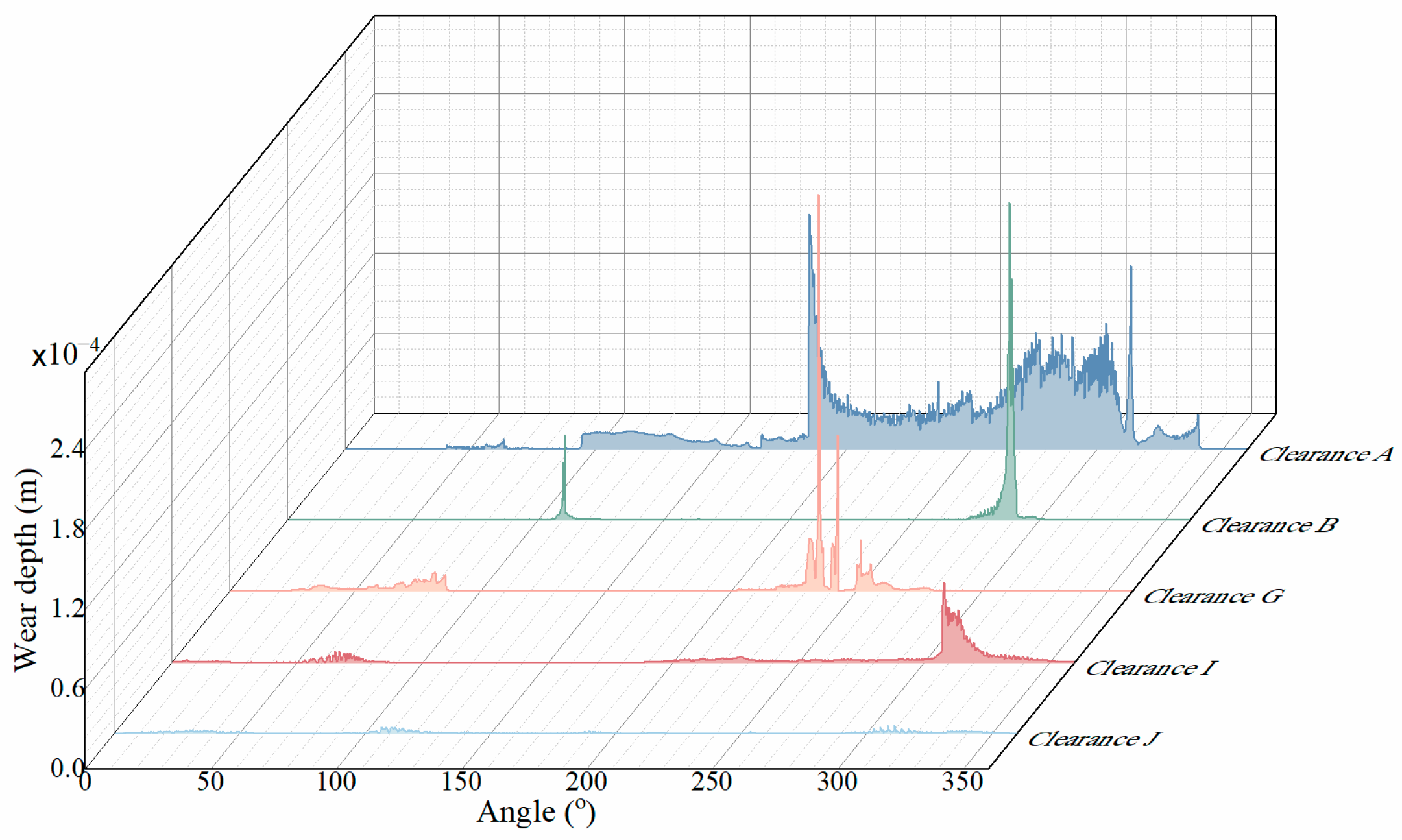
As shown in
Figure 25, the wear induced by clearance A at the driving end is the most severe, with large wear patches and deep grooves clearly observed in the image. The detailed bushing wear pattern and the corresponding locally enlarged views are presented in
Figure 26. This indicates the presence of a continuous wear region, reflecting frequent and sustained contact–separation cycles between the shaft and bushing during the transmission process. Due to its close proximity to the driving source, the impact energy is rapidly concentrated and released at the contact interface over a short path, resulting in intense friction and representing a typical high-intensity impact wear pattern. Although clearance B is also located near the driving side, its wear severity is notably lower than that of clearance A. As shown in
Figure 27, the wear image shows sparse patches and narrow parallel scratches. The shaft–bushing interface exhibits the most pronounced penetration in the angular range of [160°, 170°], indicating this zone as a localized wear-prone region that warrants special attention. Clearance G presents moderate wear characteristics. As shown in
Figure 28, the image reveals widespread fine scratches, with the most severe wear occurring between [200°, 220°]. In
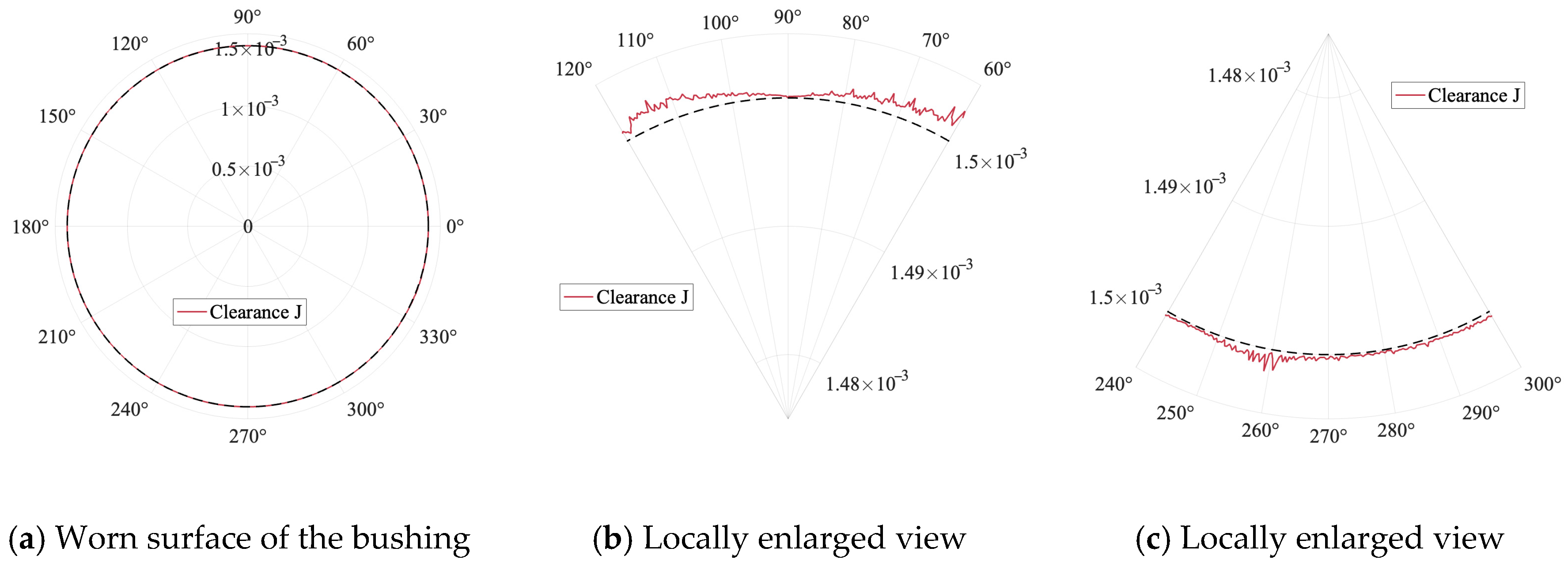
Figure 29, the wear distribution at clearance I appears in an elliptical pattern with clear boundaries, and the high-wear zone is located between [100°, 160°]. As this clearance corresponds to the distal structure of the lower leg bone, the transmitted disturbance—though partially dissipated by clearance G—can still accumulate sufficient contact energy due to the low position of the component’s center of mass, leading to a large-area continuous wear zone. In contrast, the wear at clearance J is extremely mild. As shown in
Figure 30, the wear depth remains below 10
−5 m, which is significantly lower than that observed at other revolute joint locations under the same conditions. Under magnification, continuous but shallow wear marks can still be identified.
In addition, considering that clearance J simulates the joint between the tendon and the foot, although in real biological systems it may exhibit high compliance and response sensitivity, in the rigid-body model it plays a special role in maintaining the stability of the executing component. As a result, it is difficult to form stable and sustained contact pressure, and under compound disturbances it presents a typical “insufficient contact energy–induced low-wear characteristic.” Therefore, in rigid-body systems without flexible modeling, terminal asymmetric connection sites, even when clearances exist, contribute negligibly to the wear response and can be appropriately simplified in analysis. This behavior is completely different from the phenomenon observed when only foot clearances are considered.
It is worth noting that the wear behavior of clearance A differs between the case of a single clearance and that of multiple clearances. Although clearance A exhibits large-area continuous wear in both scenarios, the wear magnitude is relatively lower when only a single clearance is considered. In contrast, under the coexistence of multiple clearances, clearance A not only retains the characteristic of large-area continuous wear but also develops the greatest wear depth among the five clearances. This indicates that the presence of multiple clearances may impose stronger impacts on the clearance connected to the driving unit, thereby aggravating its wear condition. Consequently, clearance A demonstrates a combination of large-area continuous wear and high wear depth, making it the most critical location affecting the stability and service life of the mechanism.
7.3. Chaotic Analysis of a Bionic Humanoid Leg Mechanism with Multi-Location Joint Clearances
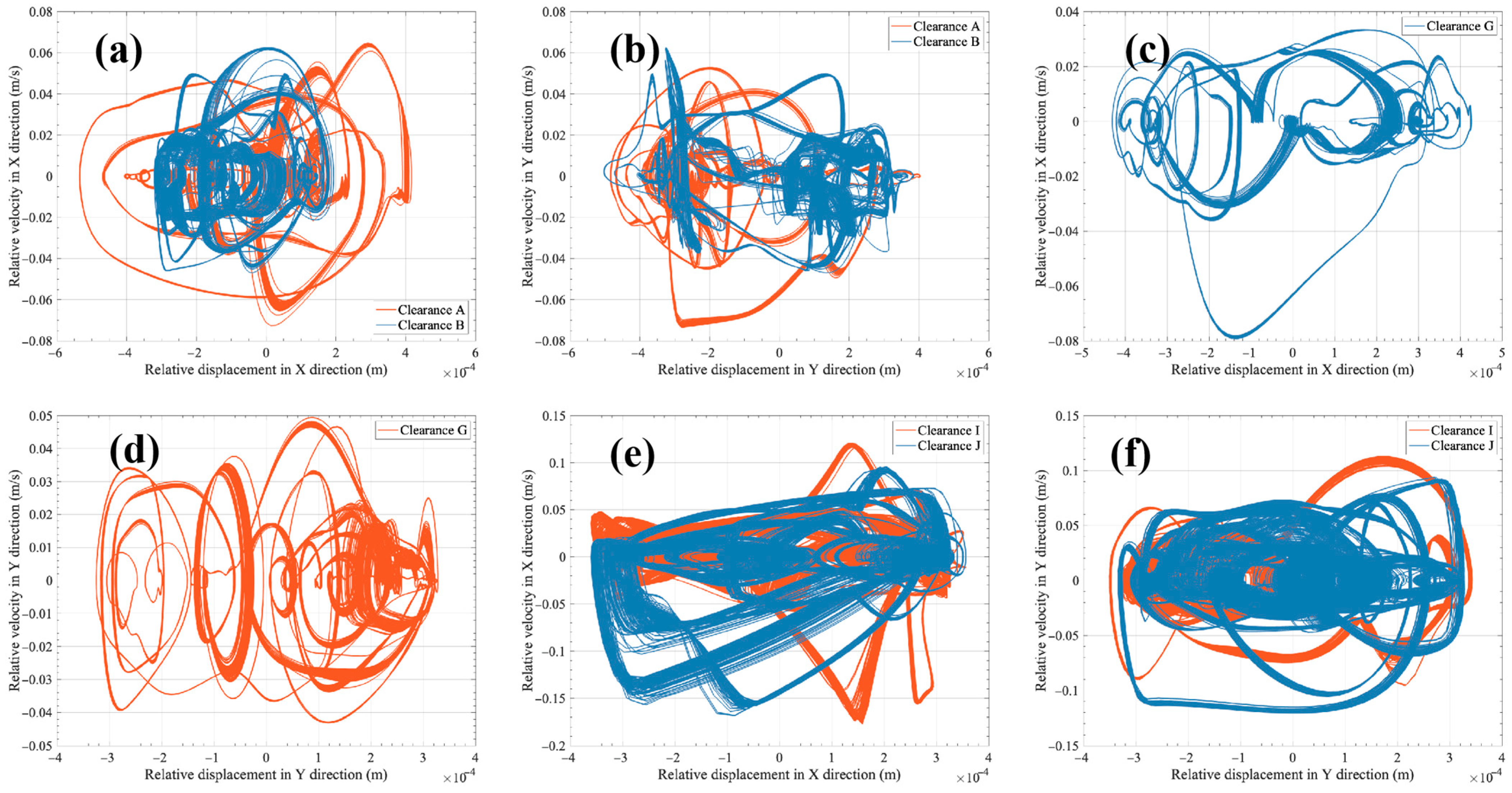
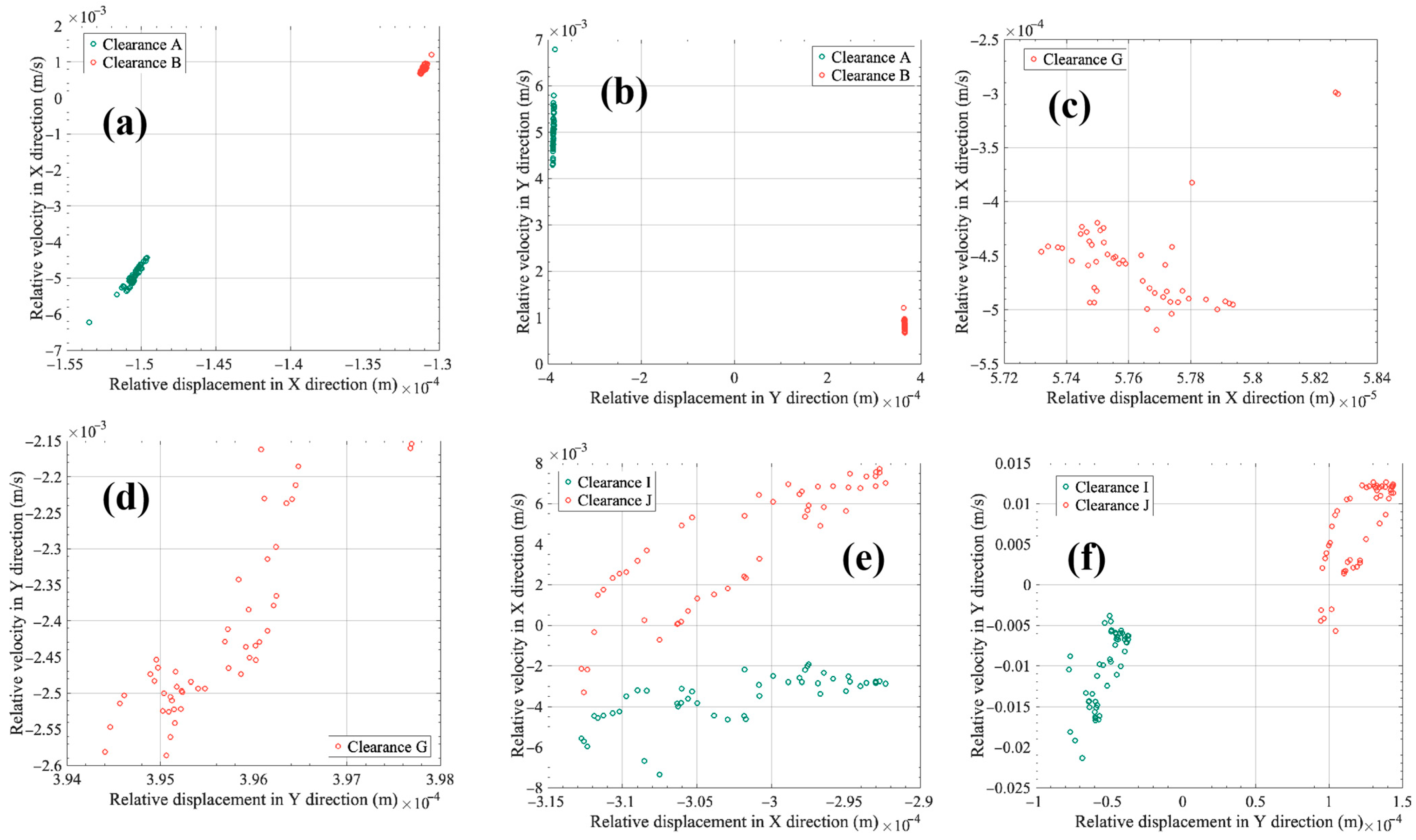
To further reveal the nonlinear dynamic behavior of each clearance under the coexistence of multiple revolute joint clearances, this section analyzes the phase portraits of key clearance locations in both the X and Y directions to identify potential nonlinear oscillations and chaotic behavior patterns of the system.
As shown in
Figure 31 and
Figure 32, the phase portraits and Poincaré maps corresponding to hip joint clearances (clearances A and B) are relatively concentrated in both X and Y directions. However, distinct differences are observed in their phase portraits. In the X direction, the phase portrait at clearance A displays relatively regular boundaries and structured motion patterns, which can be attributed to its special location at the driving end. In contrast, the phase portrait at clearance B exhibits a tendency toward trajectory divergence in the same direction, indicating a more chaotic system response. In the Y direction, the trajectory range at clearance A remains relatively stable, while clearance B shows further divergence and disorder, exhibiting more pronounced irregularity. At clearance G, both the phase portrait and the Poincaré map exhibit evident nonlinear characteristics in both X and Y directions, suggesting a certain degree of disordered behavior. This is especially true in the Y direction, where the trajectories become more divergent and chaotic. Clearances I and J exhibit the highest level of disorder among all tested positions, revealing the most prominent features of chaotic motion. This indicates the presence of strong nonlinear dynamics and highly irregular motion states at these locations.
In summary, all clearance locations exhibit a certain degree of disorder in both the X and Y directions, with clearance J showing the strongest intensity. This indicates that all locations demonstrate high sensitivity and unpredictability.