Article

Tribo-Dynamics and Fretting Behavior of Connecting Rod Big-End Bearings in Internal Combustion Engines

1
Suzhou Nuclear Power Research Institute, Shenzhen 518000, China
2
National Engineering Research Center for Nuclear Power Plant Safety & Reliability, Shenzhen 518000, China
3
School of Mechanical Engineering, Shanghai Jiaotong University, Shanghai 200240, China
4
Key Laboratory for Power Machinery and Engineering of Ministry of Education, Shanghai Jiaotong University, Shanghai 200240, China
*
Authors to whom correspondence should be addressed.
Lubricants 2025, 13(9), 376; https://doi.org/10.3390/lubricants13090376 (registering DOI)
Submission received: 15 June 2025 / Revised: 11 August 2025 / Accepted: 19 August 2025 / Published: 23 August 2025

Abstract

With the increased power density of internal combustion engines (ICE) and growing demands for lightweight design, the connecting rod big-end bearings are subjected to significant alternating loads. Consequently, the interference–fit interfaces become susceptible to fretting damage, which can markedly shorten engine service life and impair reliability. In the present study, the effects of the big end manufacturing process, bolt preload, and bearing bush interference fit are considered to develop a coupled lubrication–dynamic model of the connecting rod big-end bearing. This model investigates the fretting damage issue in the bearing bush of a marine diesel engine’s connecting rod big end. The results indicate that the relatively low stiffness of the big end is the primary cause of bearing bush fretting damage. Interference fit markedly affects fretting wear on the bush back, whereas the influence of bolt preload is secondary; nevertheless, a decrease in either parameter enlarges the fretting distance. Based on these findings, an optimized design scheme is proposed.

1. Introduction

To meet increasingly stringent emission regulations and fuel economy requirements, demands for higher power density and lightweight design in engines are growing [1]. However, these measures can lead to a reduction in the overall stiffness of critical components, such as connecting rods and engine blocks. This decreased stiffness makes the contact surfaces between components more susceptible to relative slip, consequently inducing fretting damage on these interfaces. Fretting refers to the occurrence of extremely small-amplitude relative motion (typically 1–100 μm) between two contacting surfaces [2,3]. Considering the development trends within the engine sector, the tribological conditions for engine components in the future, particularly for big-end bearings in heavy-duty engines [4], are anticipated to shift towards mixed and boundary lubrication states [5]. Under these conditions, the lubricant film thickness on big-end bearing surfaces becomes critically thin, leading to a state where asperity contact becomes increasingly dominant and severe, heightening the risk of surface damage and wear [6]. Therefore, a thorough investigation into the tribological characteristics of the big-end bearing system is crucial for enhancing the reliability of engine systems.
The bearing bush, as a primary component of the engine bearing pair, is prone to failure during operation due to the influence of complex alternating external load excitation. During engine operation, gas loads and inertial forces induce deformation of the connecting rod. These deformations locally reduce the contact pressure of the interference fit between the bearing bush and the connecting rod, while simultaneously applying shear traction stresses at the interface. Common failure modes of the bearing bush include seizure (melting/scuffing) of the sliding surface, surface overheating, bush fatigue, surface wear, fretting wear, as well as corrosion, adhesion, and cavitation damage. Fretting wear is a type of wear generated by very small relative sliding between two contacting surfaces. During engine operation, the cyclic variation in cylinder pressure leads to periodic changes in the contact pressure on the inner surface of the bearing bush. Furthermore, the differing material properties of the bearing bush and the big-end bore cause disparities in the deformation at the contact interface. This induces persistent relative slip between the bush back surface and the big-end bore surface, consequently resulting in fretting wear [7]. Fretting wear on the back of the bearing bush not only contributes to fretting fatigue in both the bush and the connecting rod, but also alters the stiffness and contact conformity of the interference–fit interface. This, in turn, affects the deformation and oil film distribution on the inner surface of the bush, thereby impairing the bearing’s lubrication performance.
Moreover, if the fretting of the bearing bush ultimately leads to significant relative slip or rotation between the bush and the big-end bore of the connecting rod, it may obstruct the oil supply passages, including the direct piston oil (DPO) gallery. This can compromise lubrication and heat dissipation not only for the bearing but also for the piston pin, potentially degrading its tribological behavior. If the small end of the connecting rod includes a press-fitted bush, such conditions may further induce fretting or loosening at the bush/small end interface. Wang et al. [8] studied the effect of the shape and position of the oil supply cooling channel on the low-cycle fatigue of engine pistons. Peng et al. [9] studied the oil filling rate and heat transfer coefficient of the cooling channel at different crankshaft angles. These studies both demonstrate the importance of the DPO gallery for pistons. Therefore, investigating bearing bush fretting wear is of significant importance for improving the fatigue durability of the bush itself, enhancing overall engine lubrication performance, and mitigating friction and wear. A specific case of fretting damage in the big-end bearing of an 18-cylinder marine engine resulted in total engine failure. This study takes this engine as the research subject. By establishing a precise multi-body lubrication dynamic model, the actual operational loads on the bearing are calculated. Concurrently, integrating considerations of the connecting rod assembly process, the impact of bearing bush fretting behavior is analyzed.
In recent years, numerous researchers have investigated the calculation of lubrication performance for big-end bearings. Several of these studies have focused on developing advanced numerical models. The objective of these models is to enable the cost-effective prediction and analysis of big-end bearing operational performance during the early stages of engine design. Razavykia et al. [10] conducted a hydrodynamic lubrication analysis of the connecting rod big-end bearing, investigating the influence of operating conditions on tribological performance. However, this model neglected the effect of bearing elastic deformation. Similarly, Zhao et al. [11] created a planar multi-body system to analyze the lubrication of the connecting rod big-end bearing, examining the effects of clearance and lubricant viscosity on lubrication performance. Moon et al. [12] developed a numerical algorithm coupling multi-body system dynamics with hydrodynamic lubrication analysis, studying the big-end bearing lubrication performance under varying clearances and lubricant temperatures. Bukovnik et al. [13] compared different models for simulating the transient response of radial bearings in ICE, incorporating bearing elastic deformation but neglecting the influence of asperity contact. Zhu et al. [14] analyzed the lubrication of both the connecting rod small-end bush and the big-end bearing, considering the effects of elastic deformation and cavitation. Profito et al. [15] used a partitioned fluid–structure interaction approach to solve the mixed elastohydrodynamic lubrication problem for a dynamically loaded connecting rod big-end bearing. Ma et al. [16,17] performed an elastohydrodynamic lubrication (EHL) analysis of radial sliding bearings in ICE using a multi-body system approach, accounting for the elasticity and dynamics of connected components such as the crankshaft and connecting rod.
Regarding research on connecting rod fretting, Badding et al. [3] proposed a method to predict the potential for fretting damage between the connecting rod and its big-end bearing bush. They used ABAQUS to compute the contact behavior between the bush and the connecting rod. However, the oil film load was simulated by applying pressure via a rigid cylinder, leading to errors in the calculation of the oil film pressure distribution. Merritt et al. [7] investigated the influence of fretting behavior at the big-end bore on connecting rod fatigue fracture. They employed bearing EHL analysis to obtain the oil film pressure load. Nevertheless, when calculating elastic deformation, they utilized the radial stiffness matrix of the bearing inner bore, which fails to capture the coupled interaction between system dynamics and the oil film. Son et al. [18] employed a flexible multi-body dynamics analysis incorporating an elastohydrodynamic model to calculate the actual loads over an engine cycle. They predicted the potential for connecting rod fretting using the Ruiz criterion. Mäntylä et al. [19] performed contact analysis on the connecting rod big end to assess fretting risk, considering assembly loads, manufacturing processes, and realistic oil film loads, while also accounting for the evolution of the local coefficient of friction. Chao [20] studied connecting rod failure mechanisms, with results indicating that engine failure was caused by fretting fatigue stemming from relative fretting motion between the bush back and the big-end bore. Renso et al. [21] examined the effect of assembly parameters on fretting phenomena in connecting rod big-end bearings. They found that bearing bush interference fit and the coefficient of friction significantly influence the Ruiz parameter. In summary, research on connecting rod fretting behavior is of significant importance. Accurate computational analysis necessitates considering the influence of multiple factors, including oil film loads and assembly loads, rendering the solution process highly complex.
To address the aforementioned challenges, this study establishes a finite element (FE) model to simulate the fretting behavior of the connecting rod big-end bearing. The model explicitly incorporates the influence of the connecting rod manufacturing process and realistic oil film loads. Multi-body lubrication dynamics simulation is employed to obtain the inertial loads acting on system components and the oil film pressure distribution within the bearing over a complete engine cycle. These results are subsequently applied as boundary conditions to the FE model. By analyzing the contact behavior between the bearing bush and the big-end bore throughout one engine cycle, the fretting wear distribution is determined. This predicted wear distribution is then validated against actual disassembly inspection results. Furthermore, to mitigate fretting behavior in the connecting rod big-end bearing, design improvements are proposed focusing on three key aspects: the structural design of the big end, the bolt preload, and the assembly interference fit.

2. Mixed Lubrication Model

2.1. Average Reynolds Equation

As shown in Figure 1, the lubrication domain is discretized into a mesh of rectangular elements. By unwrapping the three-dimensional inner surface of the bearing bush, the two-dimensional lubrication domain Ω for the bush is obtained. The boundary of this lubrication domain is denoted by Γ, which corresponds to the circumferential edges of the unwrapped bearing bush inner surface.
Under the assumptions of a Gaussian height distribution and isotropic roughness on the surface, as well as an adequate supply of lubricating oil, the averaged Reynolds equation [22,23] is employed to establish the lubrication model for the connecting rod big-end bearing:
x ϕ x h 3 12 μ p x + y ϕ y h 3 12 μ p y = U 2 ϕ c h y + σ c ϕ s y + ϕ c h t ,
where x and y denote the local coordinates within the lubrication domain Ω; p and h represent the oil film pressure and film thickness, respectively; μ is the dynamic viscosity of the lubricant; ϕx and ϕy are the flow factors in the x and y directions, accounting for surface roughness effects; ϕc is the contact factor, characterizing the load-sharing ratio between asperity contact and fluid pressure; σc is the composite roughness of the contacting surfaces; U signifies the relative velocity between the connecting rod big-end bearing bush and the crankpin. In addition to the oil film pressure, the fluid shear stress τ can be calculated as follows:
τ = μ u h ϕ f + ϕ f s ϕ f p h 2 p y ,
where ϕf, ϕfs and ϕfp are shear stress factors.
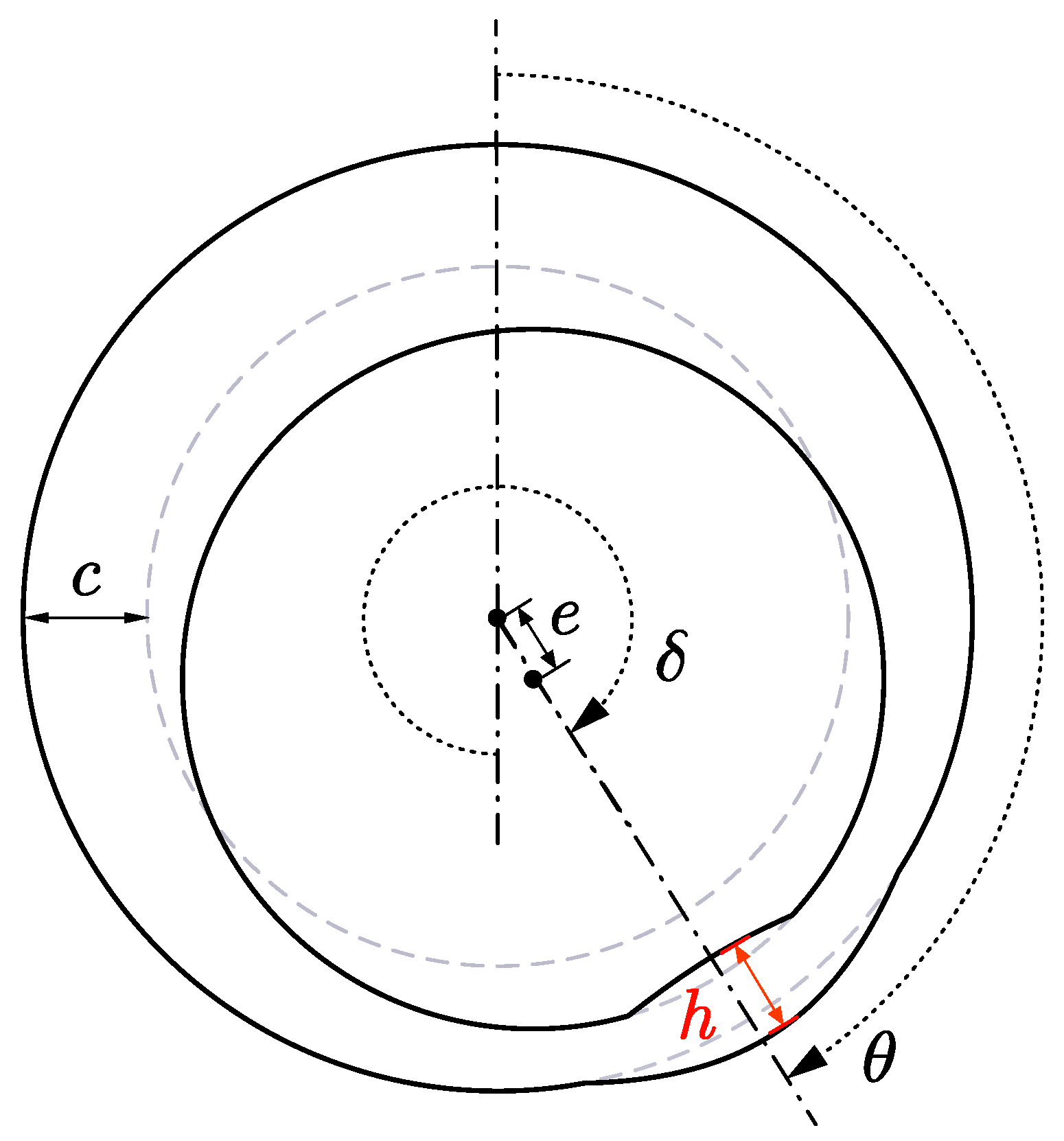
Figure 2 illustrates the schematic diagram for calculating the film thickness within the bearing conjunction. The film thickness h can be expressed by the following formula:
h = c 1 + ε cos ( θ δ ) + h prof ( x , y ) + d bush x , y , t + d crank x , y , t
where c is the bearing radial clearance; ε = e/c is the eccentricity ratio (e being the journal eccentricity); θ is the circumferential angular coordinate; δ is the attitude angle (angle of journal center displacement); dbush(x, y, t) represents the film thickness variation due to vibration and elastic deformation of the flexible bearing bush surface; dcrank(x, y, t) denotes the crankpin deformation at the position corresponding to the bearing bush; hprof(x, y) is the bearing bush profile geometry (initial machined shape).
To solve the Averaged Reynolds equation, physical boundary conditions must be applied. Assuming the pressure at the boundary of the lubrication domain Γ equals the ambient pressure, the boundary condition can be expressed as follows:
p ( x , y ) = p 0 , ( x , y ) Γ ,
where p0 denotes the ambient pressure.

2.2. Asperity Contact

In marine engines operating under high peak combustion pressures, asperity contact within the connecting rod big-end bearing becomes inevitable. This study employs the Greenwood–Tripp contact model [24] to characterize this contact behavior. The asperity contact pressure is given by the following equation:
p asp = 16 2 / 15 π ( η β σ ) 2 E σ β F 5 / 2 h σ ,
where h is the oil film thickness; σ is the standard deviation of the asperity height sum distribution; β is the radius of curvature at the peak; η is the surface density of asperity peaks; E = 1 ν 1 2 / E 1 + 1 ν 2 2 / E 2 1 is the usual composite elastic modulus, ν1 and ν1 are Poisson’s ratios, E1 and E2 are Young’s modulus; F5/2(h/σ) is the Gaussian distribution of the asperity heights, which is approximated by a polynomial function
F 5 / 2 ( H σ ) = 4.4086 × 10 5 4 H σ 6.804 , H σ 4 0 , H σ > 4 .
In addition to the aforementioned normal contact pressure, tangential friction forces develop between contacting asperities. The asperity shear traction stress is quantified as follows:
τ asp = μ b p asp ,
where μb is the boundary coefficient of friction.
The mixed lubrication model transmits the calculated pressure fields and friction tractions as generalized external forces to the flexible multi-body system. The total pressure comprises both the hydrodynamic pressure p and the asperity contact pressure pasp. Similarly, the total friction includes the fluid shear stress τ and the asperity shear traction τasp, which collectively constitute a significant contributor to frictional losses in marine engines.

2.3. FEM Solving Method

As depicted in Figure 1, for a given element Ω i e within the lubrication domain, the pressure distribution over the element can be obtained via interpolation of the nodal pressure values using shape functions N = N 1 , N 2 , N 3 , N 4 T :
p = N 1 , N 2 , N 3 , N 4 p 1 p 2 p 3 p 4 = N T p i e .
By left-multiplying the governing Equation (8) by a test function, integrating over the element domain, and performing integration by parts, the equivalent integral weak form of the average Reynolds equation can be derived as follows:
Ω i e h 3 12 μ ϕ x N x N T x + ϕ y N y N T y   d x d y p i e + Ω i e N ψ d x d y = 0 ,
where
ψ = U 2 ϕ c h y + σ c ϕ s y + ϕ c h t ,
The above equation can be rewritten in matrix form:
K i e p i e = F i e ,
with
K i e = Ω i e h 3 12 N x N T x + h 3 12 N y N T y   d x d y F i e = Ω i e N i e ψ d x d y .
Through the assembly of element diffusive and convective matrices and nodal force vectors, the governing equations for the entire lubrication domain (13) can be formulated. Solving this equation yields the global nodal pressure vector p.
K p = F .

3. Multi-Body Dynamics Model

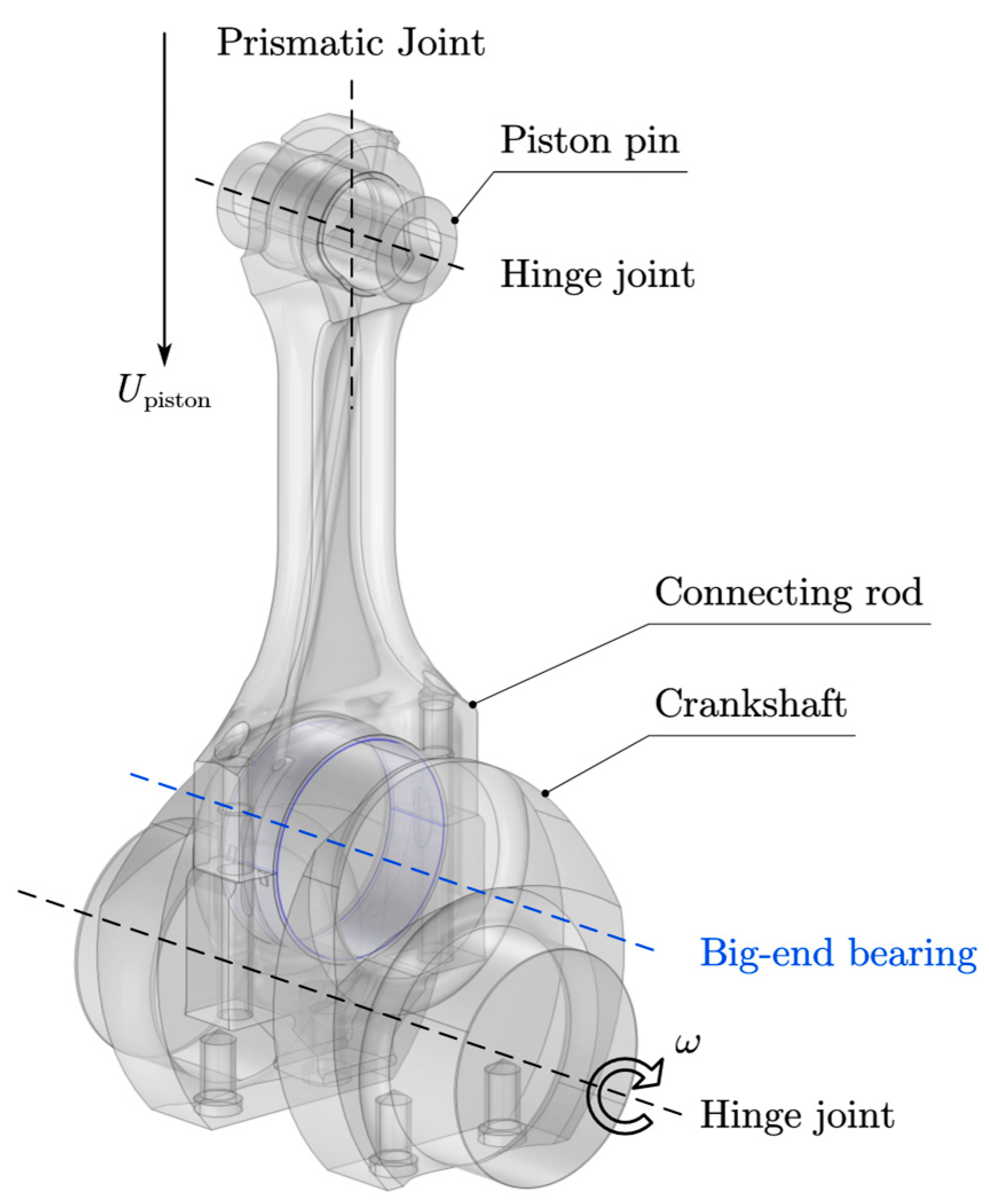
The analysis of the big-end bearing requires an understanding of its instantaneous motion posture and applied loads. Therefore, the crankshaft–connecting rod–piston system must be solved simultaneously. A schematic diagram of the engine’s crank–connecting rod–piston multi-body system is shown in Figure 3, where two hinge joints, one big-end bearing, and one prismatic joint connect the piston pin, connecting rod, and crankshaft. This study focuses on the connecting rod big-end bearing. To simplify calculations, the multi-body system does not include the piston assembly; instead, the influence of the piston assembly is equivalent to the piston pin, which is reflected by increasing the piston pin density ρpin, as shown in Table 1. Gas loads are also equivalently applied to the piston pin. During the engine’s working stroke, gas loads from the combustion chamber act on the piston pin guided by the prismatic joint. The piston pin transmits the driving force to the connecting rod, which converts the gas pressure into the crankshaft’s driving torque through the big-end bearing.

3.1. System Kinematic Equations

The following section further details the formulation process of the multi-body system dynamics equations. Components in the multi-body system are primarily constrained by reciprocating joints and revolute joints. For a specific component i in the system, the kinematic constraint equations introduced by the joints are expressed as follows:
C ( q i , t ) = 0 .
Considering the influence of constraints, the Lagrange equations with multipliers can be derived as follows:
d d t T i q ˙ i T T i q i T + C q i T λ = Q i ,
where C q i is the Jacobian constraint matrix; T i = 1 2 q ˙ i T M i q ˙ i denotes the kinetic energy of component i; Q i = K i q i + Q e i represents the generalized force vector. Substituting these into Equation (15) yields the differential dynamic equation of body i:
M i q ¨ i + K i q i + C q i T λ = Q v i + Q e i ,
where Q v i = M ˙ i q i + 1 2 q i q ˙ i T M i q ˙ i T and Q e i denote the quadratic velocity vector and generalized external force vector corresponding to body i, respectively; Mi and Ki represent the mass matrix and stiffness matrix of body i, respectively.
Assembling the differential equation systems of each body and all joint constraint equations yields a coupled differential–algebraic equation (DAE) system that describes the dynamic behavior of the system:
M q ¨ + K q + C q T λ = Q e + Q v C ( q ,   t ) = 0 .
For rigid bodies, q includes the origin position of the body coordinate system and rotational coordinates; for flexible bodies, it additionally contains an elastic coordinate vector used to describe deformation. In this study, the finite element method is employed to spatially discretize flexible bodies, thereby enabling the calculation of the elastic coordinate vector.

3.2. Coupled Solving Algorithm

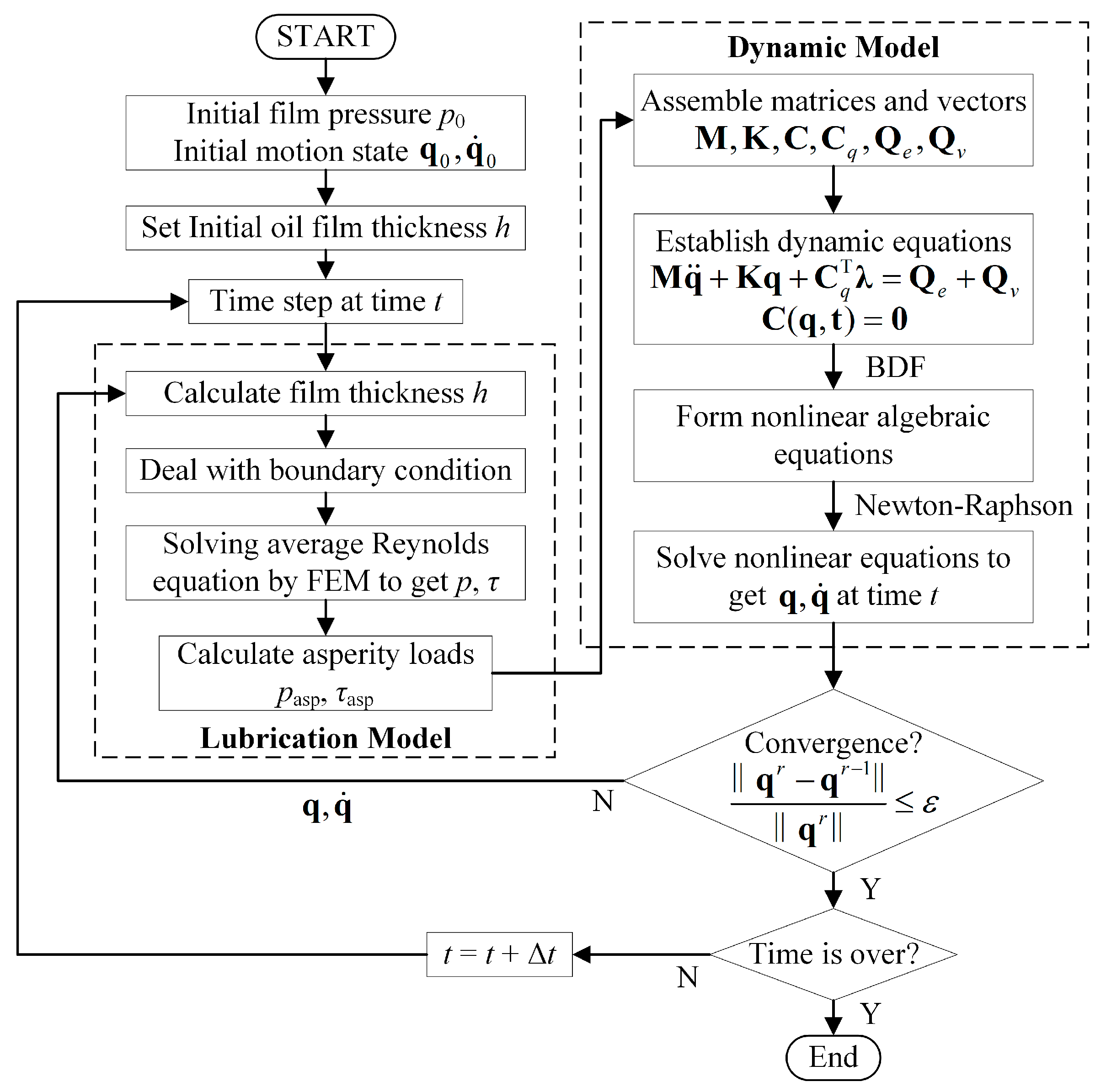
Addressing the multi-field coupling behavior within the connecting rod big-end bearing bush-journal conjunction, a mixed lubrication model for interfacial tribology and a multi-flexible body dynamics model for structural response have been separately established. Given the strong bidirectional coupling between these models, a simultaneous solution scheme is required. Figure 4 outlines the computational algorithm:
1.
Initial assembly configuration defines the generalized coordinate vector q0.
2.
Spatial positions of the bearing bush and crankpin, derived from q, determine the spatial film thickness distribution over the lubrication domain.
3.
The averaged Reynolds equation is solved via the finite element method, yielding:
(a)
Hydrodynamic pressure;
(b)
Fluid shear traction;
(c)
Asperity contact pressure;
(d)
Asperity friction traction.
4.
These tractions are integrated into generalized force vector Q input to the multi-body system.
To streamline numerical integration, the second-order differential equations of motion Equation (17) are reduced to first-order form through state–space augmentation:
M g ˙ + K q + C q T λ = Q e + Q v = Q q ˙ = g C ( q ,   t ) = 0 .
The backward differentiation formula (BDF) is employed to perform temporal discretization of the aforementioned DAE system:
M 1 Δ t β 0 g n + 1 i = 0 k α i g n i + K q n + 1 + C q T ( q n + 1 ) λ n + 1 = Q e n + 1 + Q v n + 1 1 Δ t β 0 q n + 1 i = 0 k α i q n i = g n + 1 C q n + 1 , t = 0 .
To ensure numerical stability, the computation employs a maximum BDF order of 2. As illustrated in Figure 4, at each time instant t, the system of equations is solved via the Newton–Raphson iterative method to obtain q and q ˙ satisfying the convergence tolerance. If convergence fails, the algorithm returns to the lubrication model for parameter adjustment and recalculation.
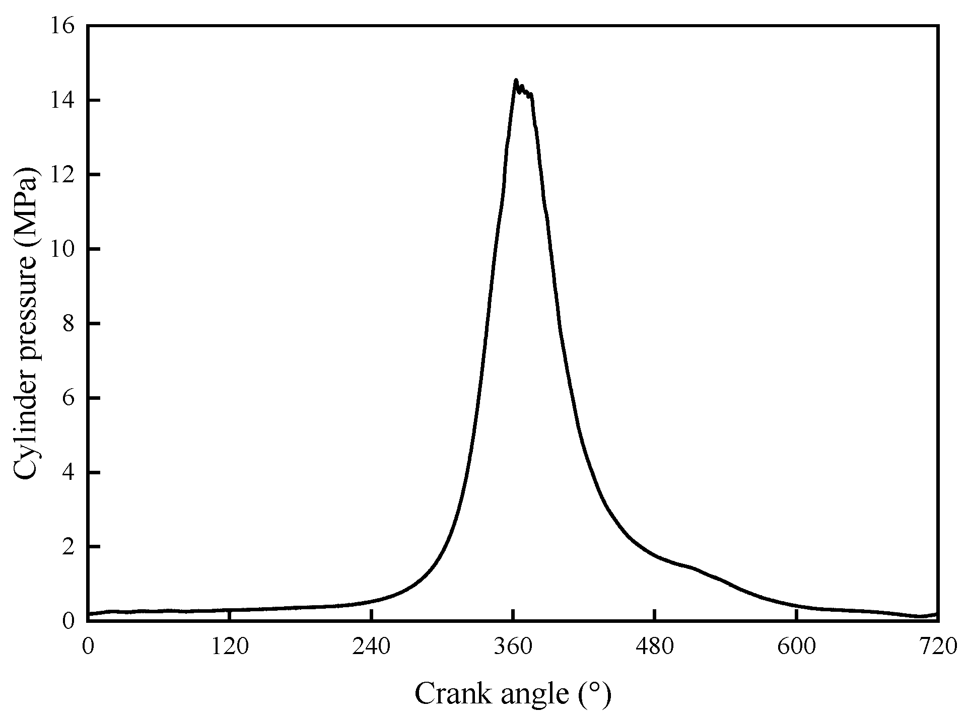
This mathematical framework is applied to a marine diesel engine with a rated speed of 1000 rpm. Essential input parameters for the simulation are provided in Table 1 and Table 2. The in-cylinder pressure profile at this operating speed, obtained experimentally, is presented in Figure 5.
Table 1. Input data for spatial rigid–flexible multi-body system.
ParametersDescriptionsValues
DBore of cylinder280 (mm)
SStroke330 (mm)
LrodLength of connecting rod660 (mm)
RCrank radius165 (mm)
nRotation speed1000 (rpm)
ρpinEquivalent density of piston pin28,850 (kg/m3)
ρrodDensity of connecting rod7850 (kg/m3)
νrodPoisson’s ratio of connecting rod0.3 (-)
ErodElastic modulus of connecting rod212 (GPa)
ρbushDensity of big-end bearing bush8900 (kg/m3)
νbushPoisson’s ratio of big-end bearing bush0.3 (-)
EbushElastic modulus of big-end bearing bush211 (GPa)
ρcrankDensity of crankshaft7850 (kg/m3)
νcrankPoisson’s ratio of crankshaft0.3 (-)
EcrankElastic modulus of crankshaft210 (GPa)
Table 2. Input data for the mixed lubrication model.
ParametersDescriptionsValues
cNominal clearance of big-end bearing120 (μm)
σComposite roughness of big-end bearing1.2 (μm)
ρoilDensity of lubricating oil860 (kg/m3)
μViscosity of lubricating oil0.039 (Pa·s)
μbBoundary coefficient of friction0.09 (-) [25]
Figure 5. Cylinder pressure curve.
Lubricants 13 00376 g005

4. Fretting Wear Model

This study employs two distinct but sequentially coupled computational domains to address multi-physics interactions in the connecting rod big-end bearing system:
Lubricated Interface (Bushing-Inner/Crankshaft Journal): Governed by a fluid–structure interaction (FSI) model (Section 2 and Section 3), resolving transient mixed lubrication behavior via the Average Reynolds equation and asperity contact (Greenwood and Tripp model). This interface assumes fully flooded hydrodynamic conditions.
Fretting Interface (Bushing-Back/Big-End Bore): Modeled as a dry, solid–solid micro-motion regime (Section 4), where fretting wear is quantified using the Archard equation. Critically, no fluid film or flooding conditions are assumed at this press-fit interface.
The models are unidirectionally coupled: hydrodynamic pressures and shear forces from the lubricated domain serve as boundary conditions for the structural analysis of the fretting interface. This approach ensures physical fidelity while avoiding conflation of lubricated and unlubricated contact mechanics.

4.1. Connecting Rod Boring Process

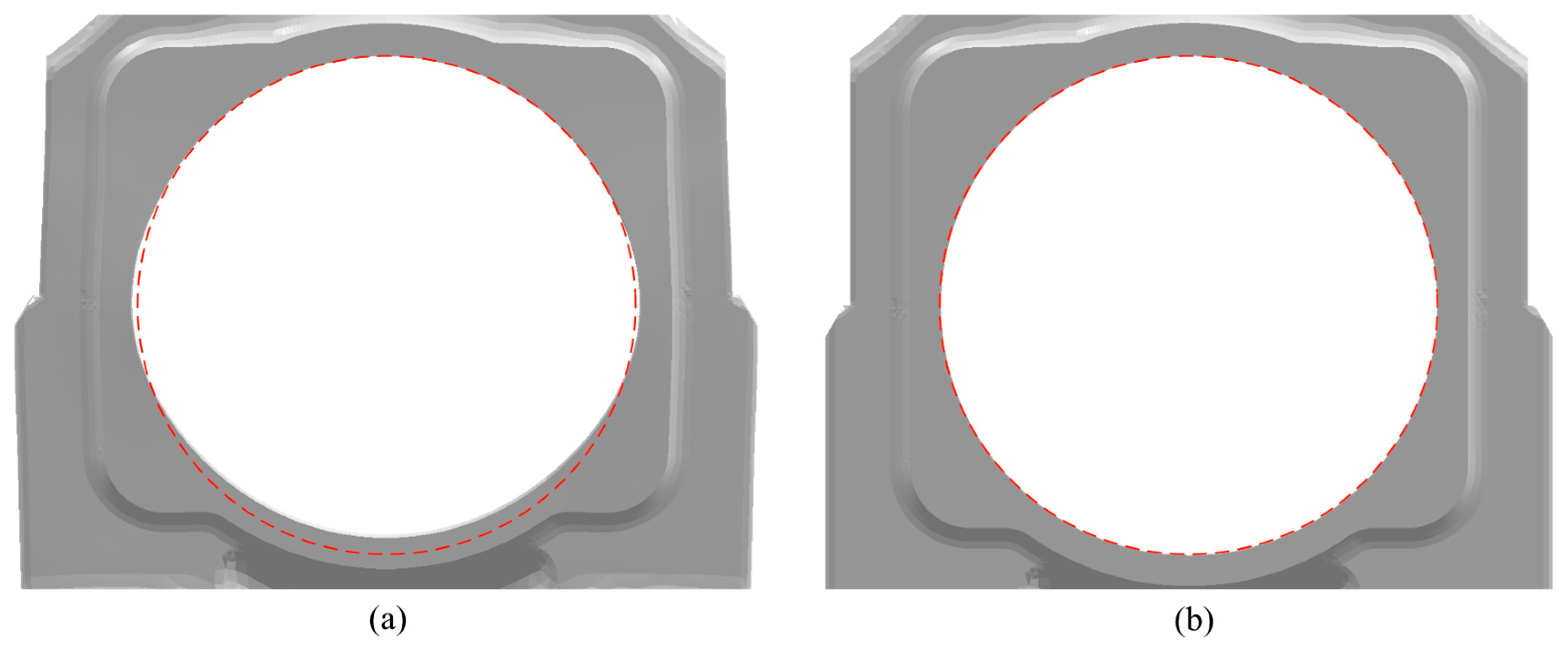
During the precision boring process of the connecting rod big-end bore, the connecting rod cap and connecting rod body are assembled via bolts. Consequently, the big-end bore maintains a cylindrical profile under specified bolt preload, whereas it exhibits a non-cylindrical shape in the free state. As illustrated in Figure 6, neglecting boring process effects leads to deviated bore geometry after bolt preload application. Performing bearing bush interference–fit analysis under such distorted bore conditions would induce undesirable deformation in the bearing bush, contradicting real assembly behavior. Therefore, accurate analysis of the big-end bearing necessitates accounting for machining process effects, requiring geometric correction of the big-end bore in its free state to ensure physically realistic contact pressure distribution after interference assembly.
This study explicitly incorporates the actual machining state of the connecting rod big-end bore in deformation analysis. The implementation procedure comprises the following steps:
  • Apply bolt preload to assemble the connecting rod body and cap, inducing non-cylindrical deformation in the big-end bore.
  • Extract nodal displacement results of the big-end bore in this deformed configuration.
  • Apply reverse deformation to the nodal coordinates of the big-end bore in the reference configuration based on the extracted displacements.
  • Verify cylindrical integrity: upon reapplication of identical bolt preload, the compensated bore recovers its nominal cylindrical form.

4.2. Calculation Methods for Fretting Wear

The Archard wear model [26] for calculating fretting wear is expressed as follows:
V s = K w F H = k 1 F ,
where V is the wear volume; s is the relative sliding distance between contacting surfaces; Kw is the experimental wear coefficient; F is the normal contact force; H is the material hardness; kl is the local wear coefficient, defined as kl = Kw/H.
To obtain nodal wear depth on the contact surface during computation, the wear depth per unit sliding distance is derived from Equation (20), as follows:
d h d s = k 1 p ,
where p denotes the local contact pressure. For practical implementation, the local wear coefficient kl poses measurement challenges. Thus, it is substituted by the global wear coefficient kg, which represents the empirically measurable average wear coefficient across the entire contact interface.
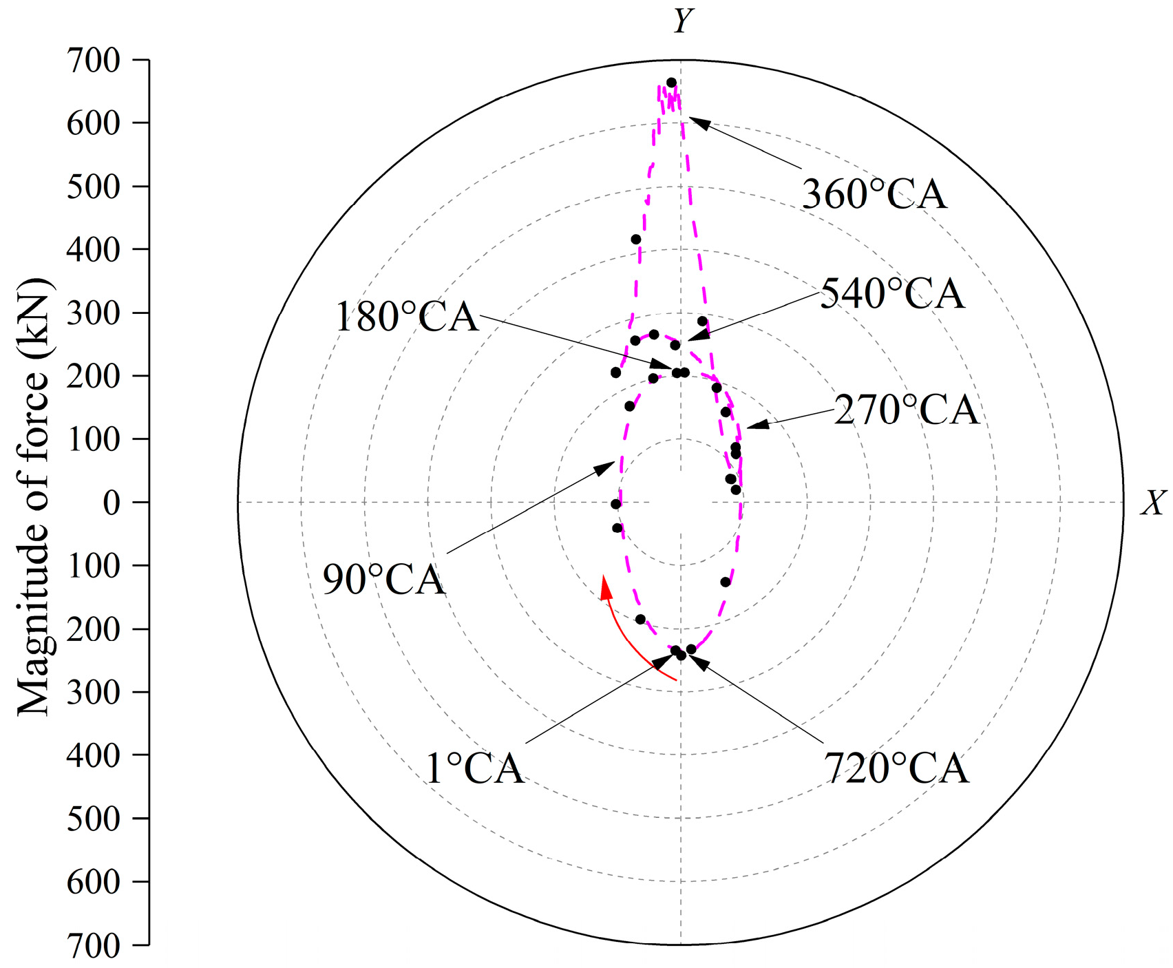
Within the finite element framework, the continuous loading process of an engine cycle is simulated via nonlinear quasi-static analysis. Specifically, the loading curve of one engine working cycle is applied to a single analysis step, which is divided into M calculation increment steps. To ensure calculation speed and efficiency, M = 26 is selected, meaning calculations are performed at 26 crankshaft angles with relatively severe loading. The selected crank angles are marked as black circular points in Figure 7, illustrating their distribution along the engine load cycle. Discretizing the integral of Equation (21), the cumulative wear depth at node k over one engine cycle is as follows:
Δ h k cycle = i = 1 M k g p k i Δ s k i ,
where p k i and Δ s k i represent the contact stress and relative slip distance at the i-th increment step for the contact surface node k, respectively.
The computational parameters utilized in the fretting behavior analysis are summarized in Table 3. To account for the effects of bolt preload attenuation and interference fit degradation, additional simulations were conducted under the following conditions: bolt clamping force decayed to 461 kN; interference amount reduced to 0.264 mm. The computational workflow comprises the following steps:
  • Boring process simulation (incorporating geometric compensation);
  • Application of bolt preload (461 kN nominal/decayed);
  • Imposition of bearing bush interference fit (0.264 mm nominal/degraded);
  • Solution of 26 characteristic crankshaft angle positions (critical loading instants);
  • Quantification of fretting slip distance and wear depth.
In terms of displacement boundary conditions, the small end part of the connecting rod is set as fully fixed. For force boundary conditions, the inertial force loads obtained from multi-body dynamics calculations are applied to the connecting rod and bearing bush, while the distributed loads calculated by the mixed lubrication model—including hydrodynamic pressure, fluid shear traction, asperity contact pressure, and asperity friction traction—are applied to the inner surface of the bearing bush.

5. Results and Discussion

5.1. Tribo-Dynamic Results

The total bearing loads obtained from the multi-body lubrication dynamics analysis are shown in Figure 7 and Figure 8. Specifically, during the intake stroke at the initial stage of the cycle (0 °CA~180 °CA), the bearing load exhibited a sequential decrease followed by an increase, accompanied by a directional reversal. Subsequently, in the first half of the compression stroke (180 °CA−270 °CA), a gradual reduction in bearing load was observed. This trend was followed by a rapid escalation of vertical load component (Y-direction) during the latter compression phase (270 °CA−360 °CA), culminating in a peak magnitude of approximately 650 kN. This load maximum temporally coincided with the cylinder pressure ignition event. The load magnitude underwent rapid attenuation during the power stroke (360 °CA−540 °CA). In the subsequent exhaust stroke (540 °CA−720 °CA), the bearing load demonstrated a characteristic pattern of initial reduction followed by gradual intensification, accompanied by another directional inversion.
Notably, the horizontal load component (X-direction) maintained minimal oscillation amplitude throughout the engine cycle, with values oscillating near the null baseline. These analytical findings substantiate that the vertical load component constitutes the predominant factor influencing big-end bearing dynamics. Furthermore, the identified strong temporal correlation between the computed bearing load and cylinder pressure profiles provides empirical validation for the numerical model’s accuracy.
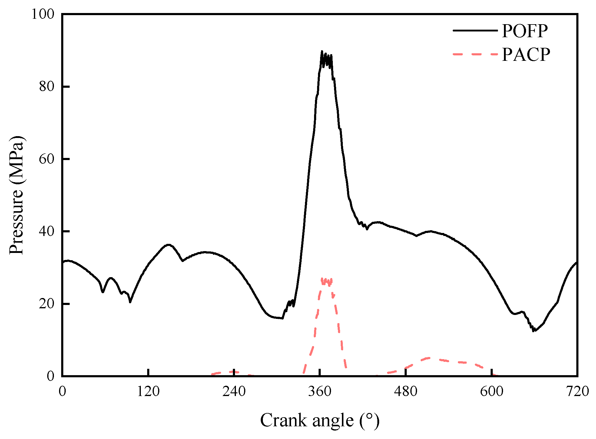
Figure 9 illustrates the cyclic variation of minimum oil film thickness (MOFT). The intake stroke exhibits relatively greater film thickness accompanied by two pronounced fluctuations, primarily attributable to bearing load reversal events. Notably, the MOFT reaches its minimum value of 1.07 μm near the cylinder pressure ignition timing (360 °CA), coinciding with the maximum bearing load phase where the asperity contact pressure was recorded at 25.58 MPa. Subsequent load reduction induces progressive film thickness recovery, ultimately achieving stabilized hydrodynamic lubrication conditions. As depicted in Figure 10, the peak oil film pressure (POFP) reached 88.2 MPa near the combustion moment (362 °CA), while the peak asperity contact pressure (PACP) also reached 22.7 MPa at this moment. At the same time, we also provide shear stress curves related to the crankshaft angle, including maximum hydrodynamic shear stress (MHSS), maximum asperity contact shear stress (MACSS) and maximum total shear stress (MTSS), as shown in Figure 11. Analytical results reveal a distinct inverse correlation between POFP fluctuations and MOFT variations: elevated bearing loads correspond to reduced film thickness and intensified film pressure, demonstrating parametric synchronization. This reciprocal relationship quantitatively validates the elastohydrodynamic coupling mechanism governing big-end bearing tribological performance.
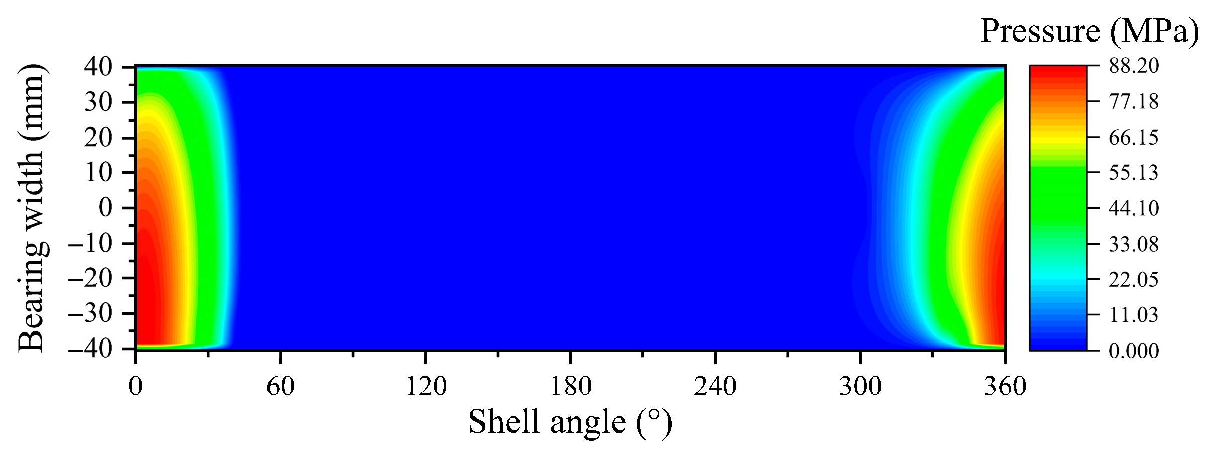
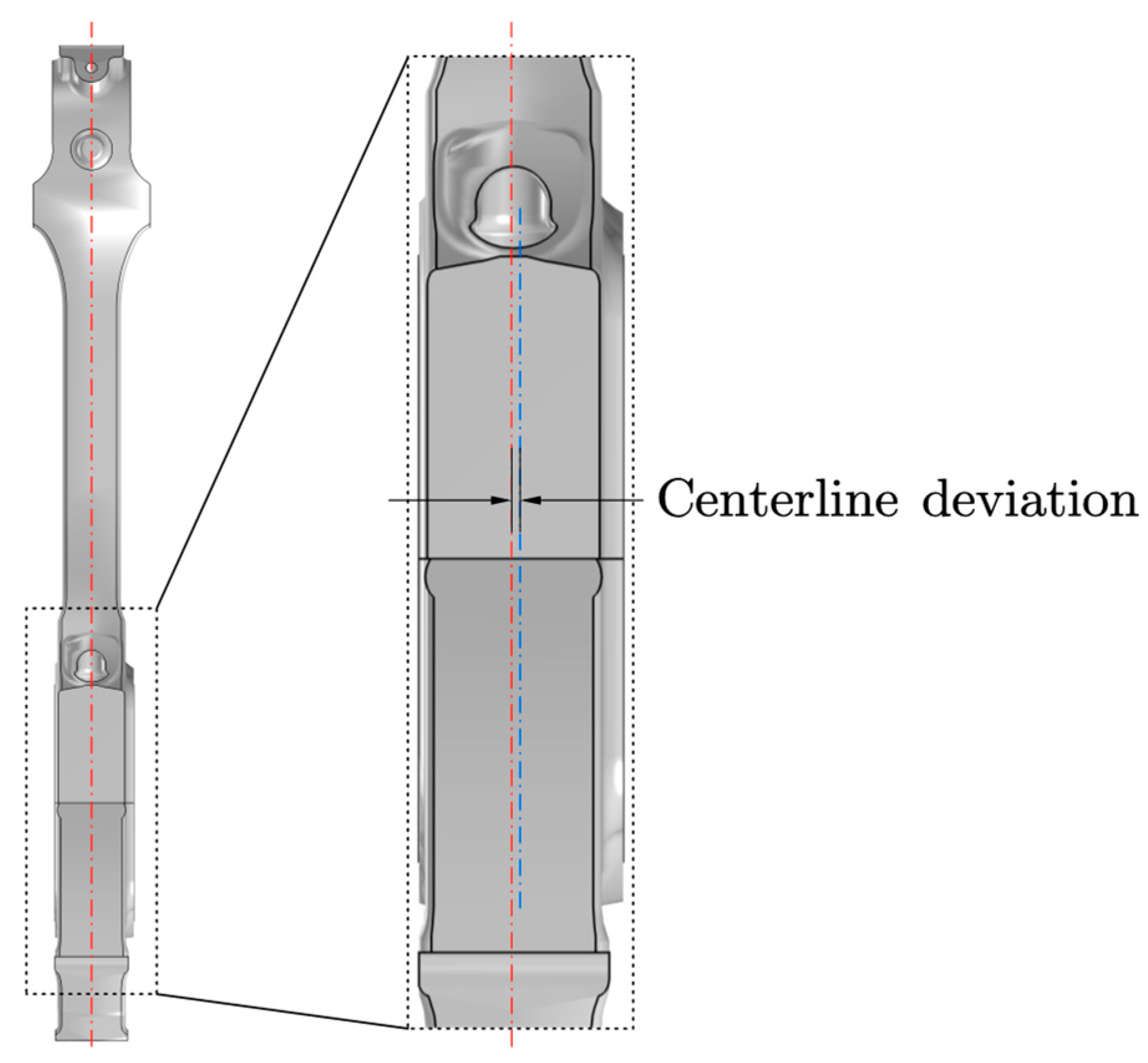
Figure 12 presents the oil film pressure profile at 362 °CA, revealing distinct eccentricity characteristics in pressure distribution. This phenomenon is mechanistically attributable to the V-configuration engine architecture with side-by-side connecting rod arrangement, which induces geometric non-coincidence between the connecting rod axis and big-end bearing centerline, as schematically illustrated in Figure 13. In the subsequent finite element model for fretting calculation, the oil film-related distributed loads across all characteristic crank angles will be systematically incorporated as time-variant boundary conditions. This computational strategy ensures rigorous consideration of transient lubrication effects on fretting evolution.

5.2. Fretting Slip Results

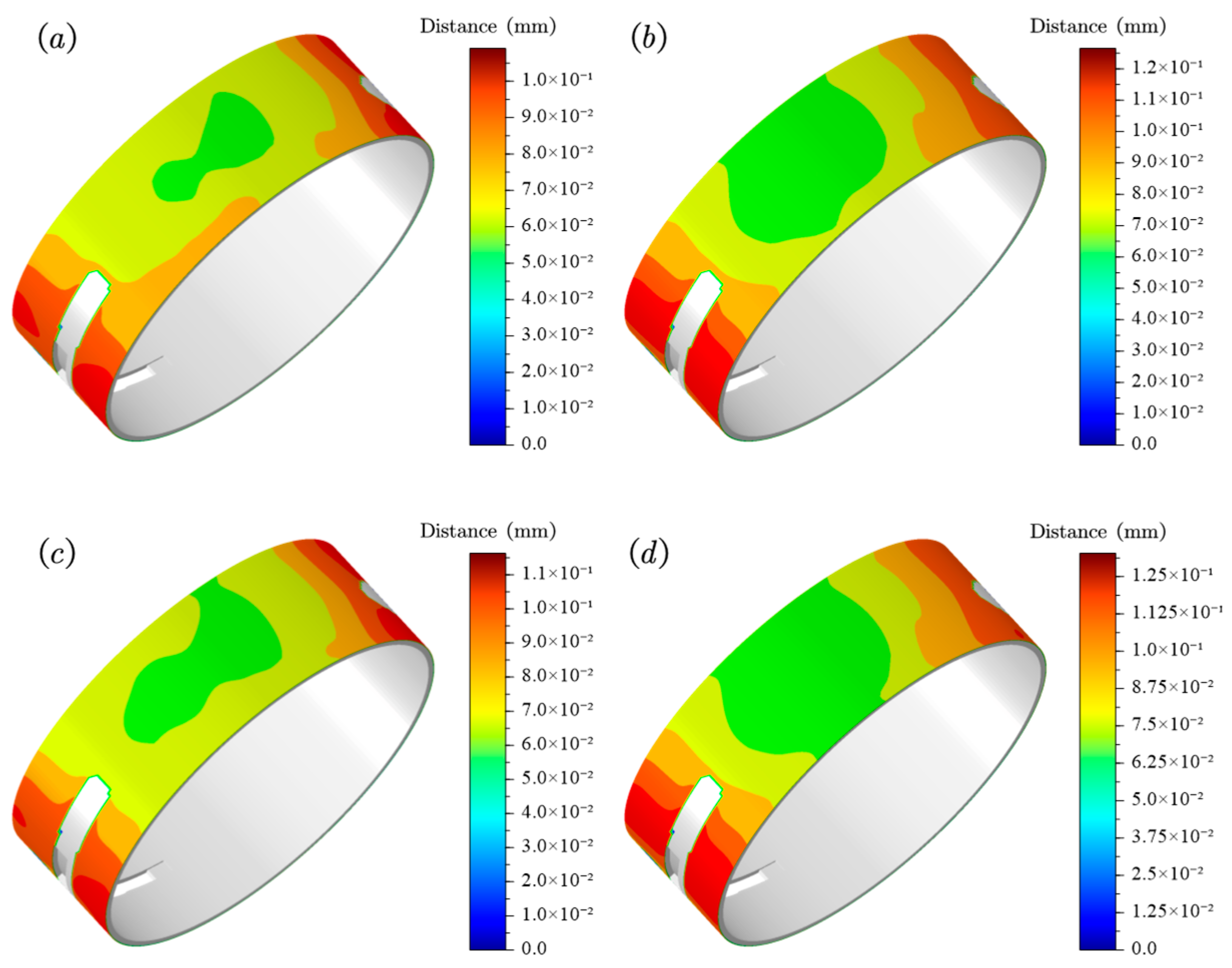
The computational results of fretting slip characteristics are presented in Figure 14. Under specified assembly parameters (Fp = 550 kN, δ = 0.31 mm), the upper bearing bush demonstrates localized variation in slip distribution: the central region exhibits relatively constrained motion compared to flank areas adjacent to lubrication grooves. Predominant fretting distance is concentrated along groove peripheries, with maximum slip distance reaching critical levels that may adversely affect lubricant replenishment efficiency.
Parametric analysis revealed a direct correlation between component degradation and slip intensification: progressive degradation of both bolt preload force and bearing bush interference fit was observed to proportionally increase maximum slip distance at groove-adjacent zones.

5.3. Fretting Wear Results

The computational results of fretting wear distribution are presented in Figure 15, indicating primary wear concentration in both the central region and lateral areas of the upper bearing bush backside. Under bolt preload degradation conditions, the wear depth at groove-adjacent zones increases, while the central region exhibits a moderate growth. This phenomenon is mechanistically attributed to enhanced big-end bore deformation resulting from reduced clamping constraints. Conversely, interference fit reduction induces a counterintuitive decrease in overall wear height, primarily driven by a reduction in backside contact pressure that outweighs the compensatory slip distance increase. When considering coupled parameter degradation, synergistic effects manifest as wear intensification at groove peripheries accompanied by attenuation in central zone wear. Quantitative comparisons detailed in Table 4 reveal distinct parameter sensitivities: a 14.84% interference reduction yields merely 4.74~6.7% slip decrease compared to a linear contact pressure reduction. The results of fretting wear under calibration conditions and assembly force decay conditions are shown in Table 5. The parametric influence factor analysis further establishes the superior impact of interference fit over bolt preload on wear evolution.
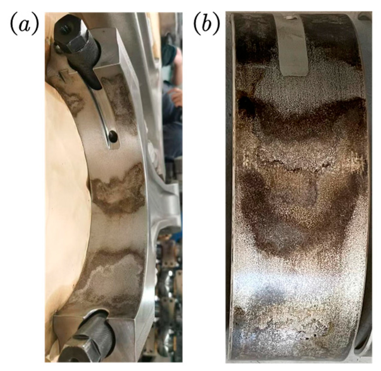
As shown in Figure 16, experimental validation through engine teardown inspection demonstrates strong concordance with computational predictions. This empirical verification confirms the model’s capability in capturing contact mechanics evolution and resolving multi-parameter coupling effects, as evidenced by its accurate reproduction of service-induced wear topography.

5.4. Analysis of Reasons for Failure

The maximum bearing bush deformation occurs near top dead center (TDC) positions during intake/exhaust strokes, as illustrated in Figure 17. Significant bush distortion creates measurable clearance between the bearing bush and big-end bore. Under bolt preload degradation from 550 kN to 461 kN, maximum deformation escalates from 0.1477 mm to 0.1862 mm, with peak deformation timing correlating strongly with maximum slip occurrence. This temporal–spatial coincidence confirms insufficient big end structural stiffness as the primary driver for excessive backside slip generation.
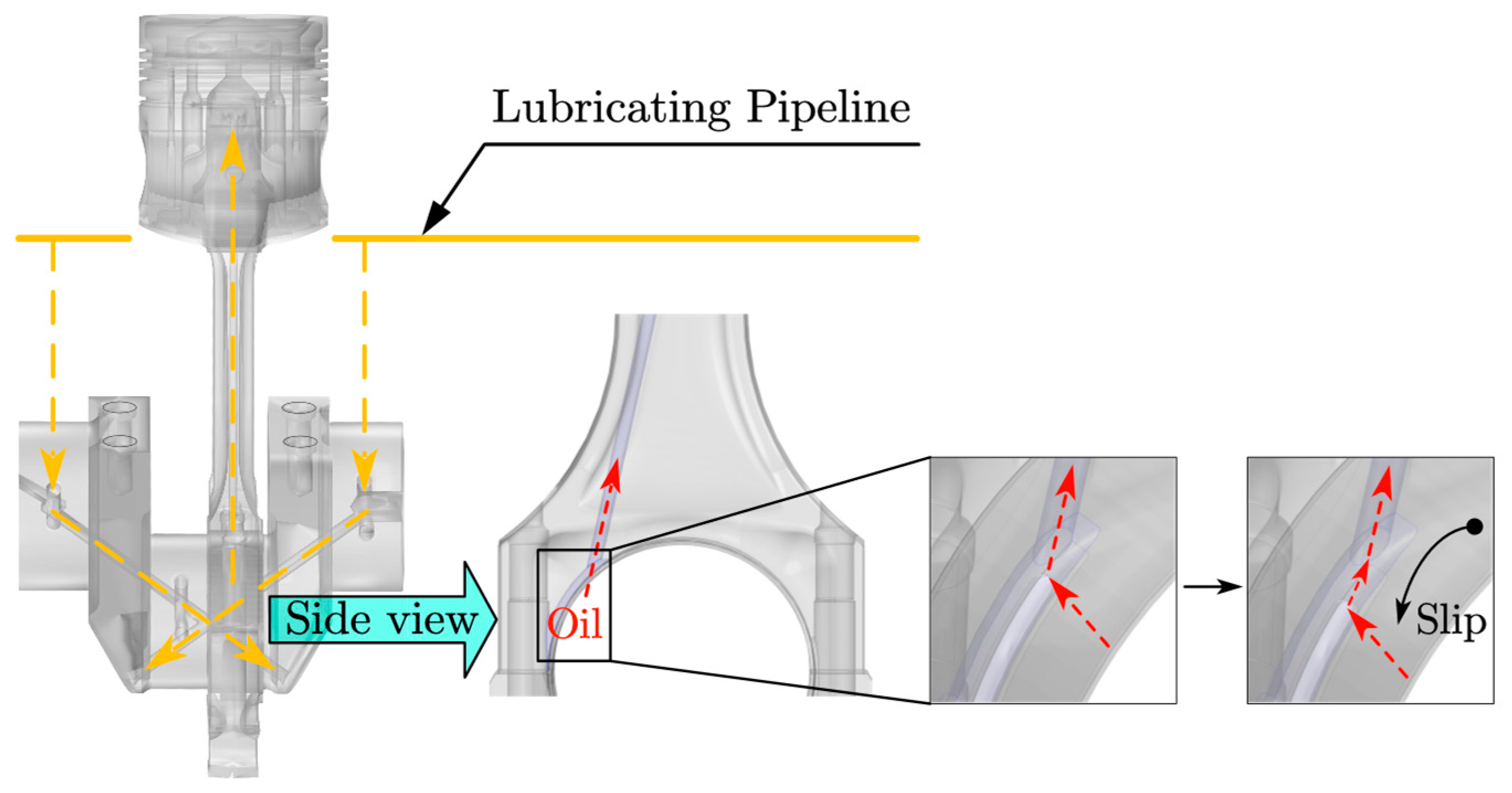
Figure 18 demonstrates normal lubricant transport mechanics, where oil flows unimpeded through bearing grooves into the connecting rod’s internal passages. However, when significant slip occurs in the bearing bush, the lubricating oil supply of the connecting rod is affected, resulting in insufficient oil supply to the piston cooling oil cavity. This leads to high temperature in the piston, potentially causing cylinder scoring or even connecting rod fracture.

5.5. Optimization Scheme

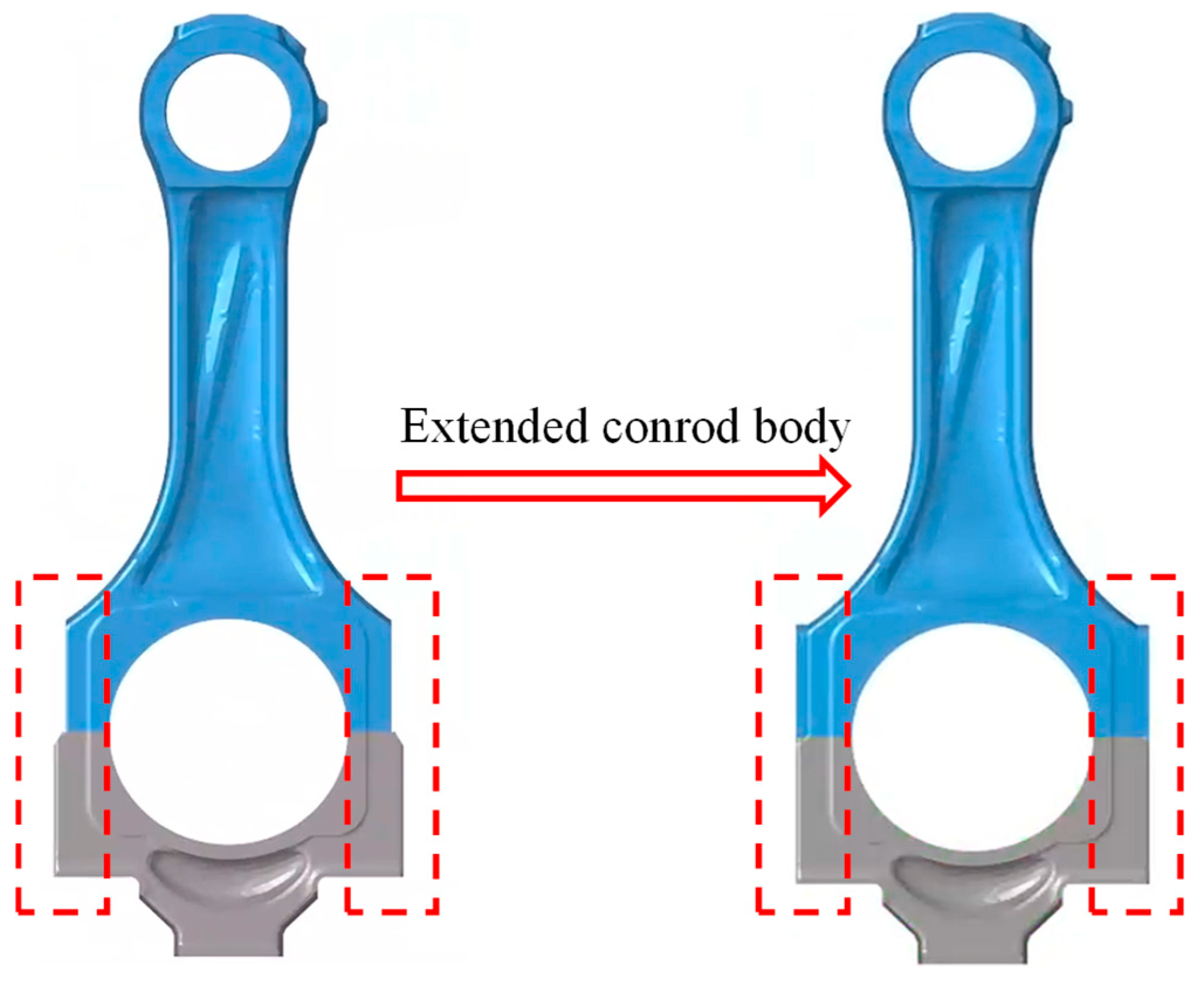
The root cause analysis identifies insufficient big end structural stiffness as the primary contributor to excessive fretting slip distance, with additional exacerbation from assembly parameter degradation (bolt preload reduction and interference fit loss). Based on these findings, the optimization strategy incorporates three synergistic modifications: structural reinforcement through connecting rod body expansion (Figure 19), controlled enhancement of bolt preload force, and calibrated increase in bearing interference fit. The term ‘synergistic’ denotes mechanistic interdependencies between these modifications: structural reinforcement reduces big end elastic deformation, establishing a stable foundation for assembly constraints; enhanced bolt preload maintains interfacial clamping force, preventing separation that would compromise the interference fit; increased interference fit directly suppresses bush-back fretting slip, but its efficacy depends on sustained contact pressure enabled by the preceding two factors.
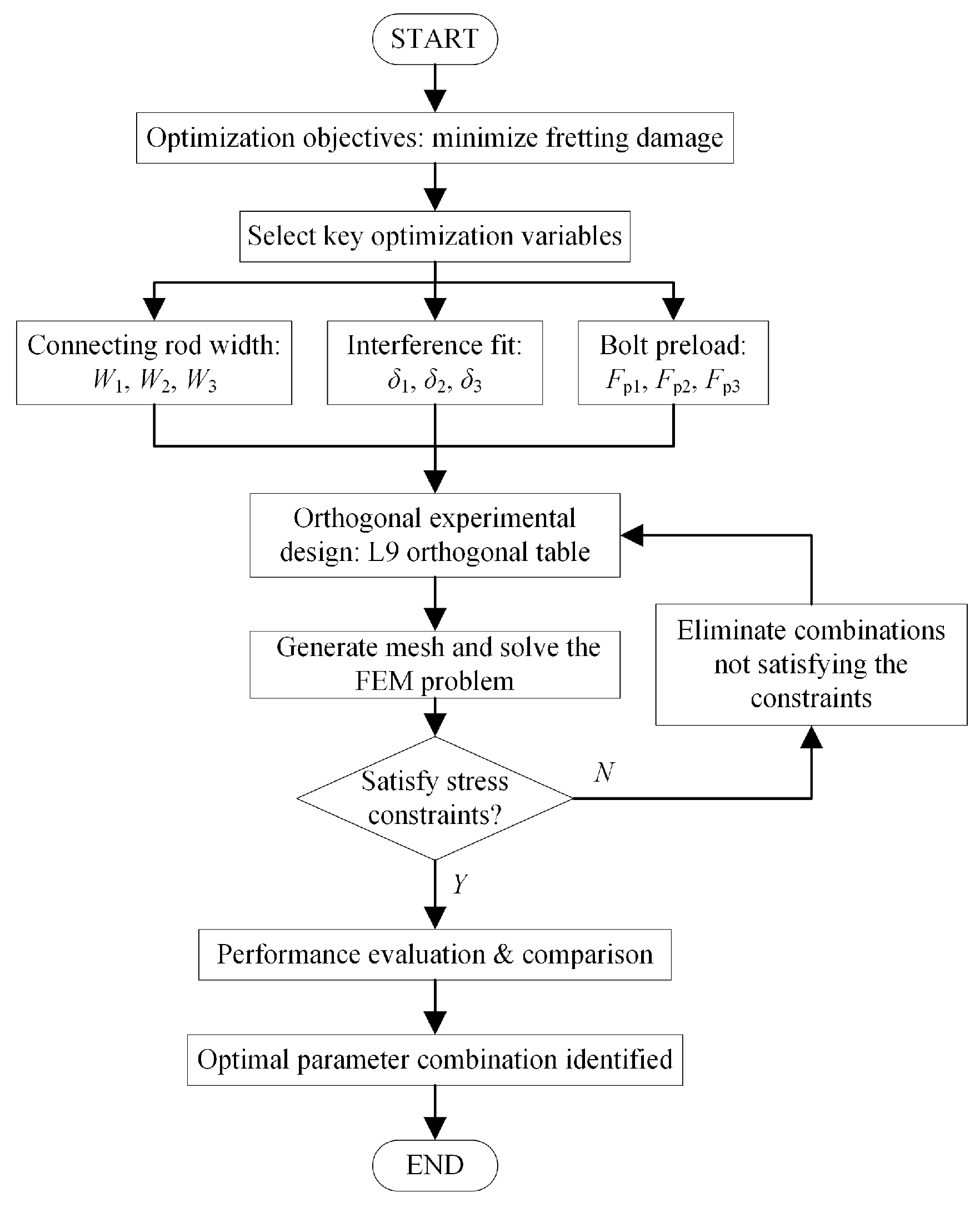
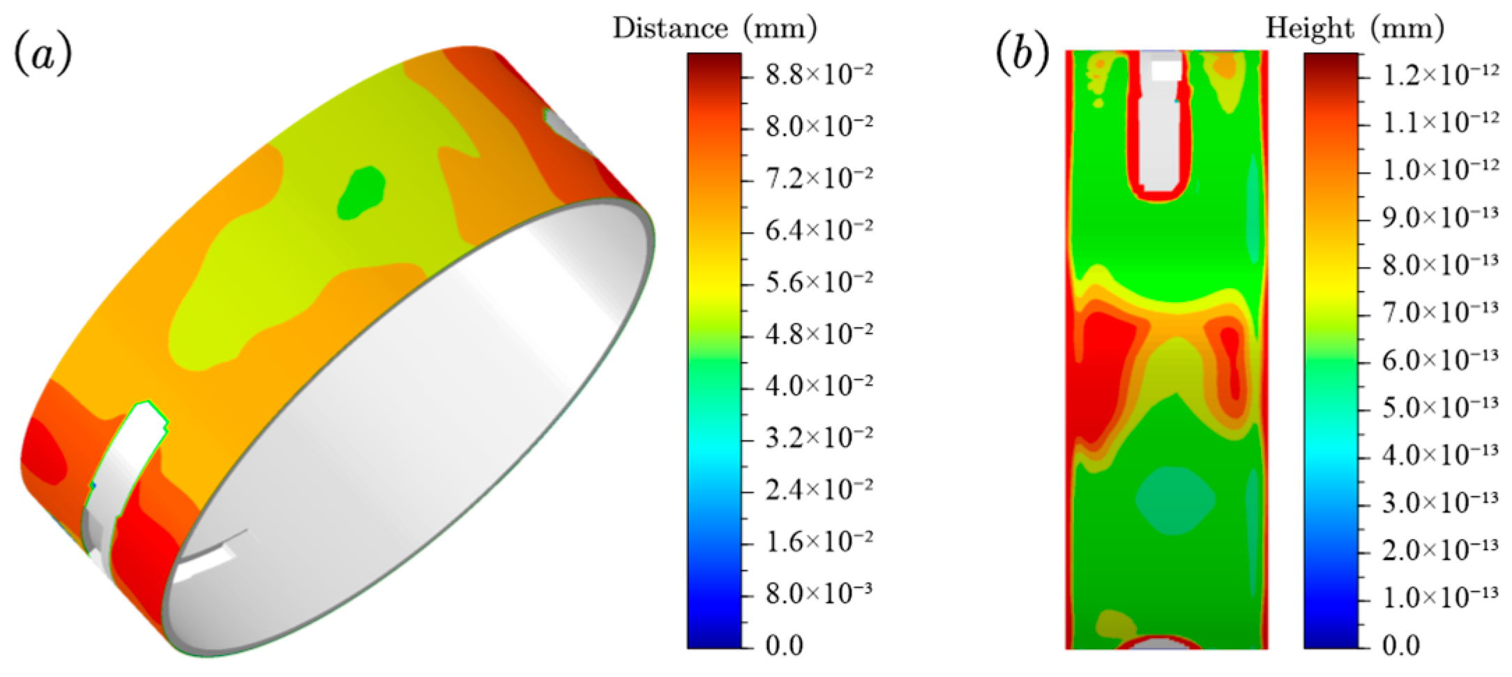
The optimization method used in this study is shown in Figure 20. The objective of the optimization is to minimize fretting damage. To ensure the reliability of the structure, a global maximum von Mises stress constraint condition was also applied. Implementation of these measures yields performance improvements, as quantified in Figure 21. Under optimized conditions (bolt preload = 580 kN, interference amount = 360 μm, with expanded rod geometry), single-cycle fretting parameters demonstrate marked reduction: compared with the ideal assembly condition shown in Figure 15a, the optimized design reduces the maximum slip distance to 0.09174 mm (a reduction of 15.83%) and the peak wear depth to 1.252 × 10⁻¹² mm (a reduction of 12.45%).

6. Conclusions

To address the overall machine failures caused by fretting damage in the connecting rod big-end bearing, this paper establishes a multi-flexible-body elastohydrodynamic lubrication model for predicting fretting slip and wear in the big-end bearing. The model fully considers the effects of big end machining processes, bolt preload, and bearing bush interference fitting on the big-end bore, enabling coupled simulation of system deformation, dynamics, and lubrication characteristics, as well as fretting analysis. The effectiveness of the analysis model is verified by actual disassembly and inspection results. The study reveals that insufficient stiffness of the connecting rod big end leads to significant fretting slip and fretting damage in the big-end bearing. Finally, the failure causes of the engine are analyzed, and an optimization scheme is proposed. After improving the big end stiffness of the connecting rod using the optimization scheme, the maximum fretting slip amount and maximum fretting wear amount are reduced by 15.83% and 12.45%, respectively.

Author Contributions

Conceptualization, M.Z. and Y.C. (Yinhui Che); methodology, M.Z.; software, M.Z. and S.L.; validation, Q.C., H.R. and N.L.; formal analysis, Y.C. (Yinhui Che); investigation, Y.C. (Yinhui Che); resources, Y.C. (Yinhui Che) and S.L.; data curation, M.Z. and S.L.; writing—original draft preparation, M.Z. and Y.C. (Yinhui Che); writing—review and editing, M.Z. and Y.C. (Yinhui Che); visualization, M.Z.; supervision, Y.C. (Yi Cui) and S.L.; project administration, Y.C. (Yinhui Che) and S.L.; funding acquisition, Y.C. (Yi Cui) and S.L. All authors have read and agreed to the published version of the manuscript.

Funding

This research was funded by the National Natural Science Foundation of China (Grant No. 52171315) and the National Natural Science Foundation of China (Grant No. 52305121).

Data Availability Statement

The original contributions presented in this study are included in the article. Further inquiries can be directed to the corresponding authors.

Conflicts of Interest

Authors Yinhui Che, Qiang Chen, Hebin Ren and Nan Li were employed by the company Suzhou Nuclear Power Research Institute. The remaining authors declare that the research was conducted in the absence of any commercial or financial relationships that could be construed as a potential conflict of interest.

References

  1. Anenberg, S.C.; Miller, J.; Minjares, R.; Du, L.; Henze, D.K.; Lacey, F.; Malley, C.S.; Emberson, L.; Franco, V.; Klimont, Z.; et al. Impacts and Mitigation of Excess Diesel-Related NOx Emissions in 11 Major Vehicle Markets. Nature 2017, 545, 467–471. [Google Scholar] [CrossRef]
  2. Waterhouse, R.B. Fretting Wear. Wear 1984, 100, 107–118. [Google Scholar] [CrossRef]
  3. Badding, B.; Bhalerao, M.; Dowell, J.P.; Gambheera, R.; Sundaram, S. A Method to Predict Fretting in Diesel Engine Connecting Rod Bearing Bores. In Proceedings of the ASME 2004 Internal Combustion Engine Division Fall Technical Conference, Long Beach, CA, USA, 24–27 October 2004; ASMEDC: Long Beach, CA, USA, 2004; pp. 607–616. [Google Scholar]
  4. Chen, J.; Randall, R.B. Intelligent Diagnosis of Bearing Knock Faults in Internal Combustion Engines Using Vibration Simulation. Mech. Mach. Theory 2016, 104, 161–176. [Google Scholar] [CrossRef]
  5. Carden, P.; Pisani, C.; Andersson, J.; Field, I.; Lainé, E.; Bansal, J.; Devine, M. The Effect of Low Viscosity Oil on the Wear, Friction and Fuel Consumption of a Heavy Duty Truck Engine. SAE Int. J. Fuels Lubr. 2013, 6, 311–319. [Google Scholar] [CrossRef]
  6. Dou, Q.; Luo, H.; Song, Y.; Zhang, Z.; Zhang, J. Failure Analysis of Diesel Engine Connecting Rod Big-End Bearing Wear Considering Coupled Clearance Lubrication Joints. Eng. Fail. Anal. 2025, 169, 109136. [Google Scholar] [CrossRef]
  7. Merritt, D.; Zhu, G. The Prediction of Connecting Rod Fretting and Fretting Initiated Fatigue Fracture; SAE Technical Paper 2004-1-3015; SAE International: Warrendale, PA, USA, 2004. [Google Scholar]
  8. Wang, B.; Wang, D.; Lei, J.; Deng, X.; Liu, Y.; Yang, H. Study on Low-Cycle Fatigue Life of Diesel Engine Piston Considering Oil Cooling Gallery Structure. Appl. Therm. Eng. 2025, 264, 125382. [Google Scholar] [CrossRef]
  9. Peng, W.; Jizu, L.; Minli, B.; Yuyan, W.; Chengzhi, H.; Liang, Z. Numerical Simulation on the Flow and Heat Transfer Process of Nanofluids inside a Piston Cooling Gallery. Numer. Heat Transf. Part Appl. 2014, 65, 378–400. [Google Scholar] [CrossRef]
  10. Razavykia, A.; Delprete, C.; Baldissera, P. Numerical Study of Power Loss and Lubrication of Connecting Rod Big-End. Lubricants 2019, 7, 47. [Google Scholar] [CrossRef]
  11. Zhao, B.; Zhou, K.; Xie, Y.-B. A New Numerical Method for Planar Multibody System with Mixed Lubricated Revolute Joint. Int. J. Mech. Sci. 2016, 113, 105–119. [Google Scholar] [CrossRef]
  12. Moon, S.M.; Cho, Y.J.; Kim, T.W. Evaluation of Lubrication Performance of Crank Pin Bearing in a Marine Diesel Engine. Friction 2018, 6, 464–471. [Google Scholar] [CrossRef]
  13. Bukovnik, S.; Dörr, N.; Čaika, V.; Bartz, W.J.; Loibnegger, B. Analysis of Diverse Simulation Models for Combustion Engine Journal Bearings and the Influence of Oil Condition. Tribol. Int. 2006, 39, 820–826. [Google Scholar] [CrossRef]
  14. Zhu, J.; Zhu, H.; Fan, S.; Xue, L.; Li, Y. A Study on the Influence of Oil Film Lubrication to the Strength of Engine Connecting Rod Components. Eng. Fail. Anal. 2016, 63, 94–105. [Google Scholar] [CrossRef]
  15. Profito, F.J.; Zachariadis, D.C.; Dini, D. Partitioned Fluid-Structure Interaction Techniques Applied to the Mixed-Elastohydrodynamic Solution of Dynamically Loaded Connecting-Rod Big-End Bearings. Tribol. Int. 2019, 140, 105767. [Google Scholar] [CrossRef]
  16. Ma, M.-T.; Loibnegger, B. Simulation of EHD Lubrication of Common-Pin Conrod Big End Bearings in High Speed IC Engines. In Proceedings of the World Tribology Congress III, Volume 2, Washington, DC, USA, 12–16 September 2005; ASMEDC: Washington, DC, USA, 2005; pp. 547–548. [Google Scholar]
  17. Ma, M.-T.; Loibnegger, B.; Herster, P. Advanced Elastohydrodynamic Analysis of Journal Bearings in IC Engines With a Multi-Body System Approach. In Proceedings of the ASME 2006 Internal Combustion Engine Division Spring Technical Conference (ICES2006), Aachen, Germany, 8–10 May 2006; ASMEDC: Aachen, Germany, 2006; pp. 709–717. [Google Scholar]
  18. Son, J.H.; Ahn, S.C.; Bae, J.G.; Ha, M.Y. Fretting Damage Prediction of Connecting Rod of Marine Diesel Engine. J. Mech. Sci. Technol. 2011, 25, 441–447. [Google Scholar] [CrossRef]
  19. Mäntylä, A.; Göös, J.; Leppänen, A.; Frondelius, T. Large Bore Engine Connecting Rod Fretting Analysis. Raken. Mek. 2017, 50, 239–243. [Google Scholar] [CrossRef]
  20. Chao, J. Fretting-Fatigue Induced Failure of a Connecting Rod. Eng. Fail. Anal. 2019, 96, 186–201. [Google Scholar] [CrossRef]
  21. Renso, F.; Barbieri, S.G.; Mangeruga, V.; Giacopini, M. Finite Element Analysis of the Influence of the Assembly Parameters on the Fretting Phenomena at the Bearing/Big End Interface in High-Performance Connecting Rods. Lubricants 2023, 11, 375. [Google Scholar] [CrossRef]
  22. Patir, N.; Cheng, H.S. Application of Average Flow Model to Lubrication between Rough Sliding Surfaces. J. Lubr. Technol. 1979, 101, 220–229. [Google Scholar] [CrossRef]
  23. Wu, C.; Zheng, L. An Average Reynolds Equation for Partial Film Lubrication With a Contact Factor. J. Tribol. 1989, 111, 188–191. [Google Scholar] [CrossRef]
  24. Greenwood, J.A.; Tripp, J.H. The Contact of Two Nominally Flat Rough Surfaces. Proc. Inst. Mech. Eng. 1970, 185, 625–633. [Google Scholar] [CrossRef]
  25. Gao, L.; Liu, S.; Cui, Y.; Zhang, M.; Xu, Z.; Meng, X. A New Coupled Multi-Physics Modeling Method for Flexible PRCL Conjunctions. Int. J. Mech. Sci. 2025, 287, 109956. [Google Scholar] [CrossRef]
  26. Archard, J.F. Contact and Rubbing of Flat Surfaces. J. Appl. Phys. 1953, 24, 981–988. [Google Scholar] [CrossRef]
Figure 1. Connecting rod big-end bearing lubrication domain.
Lubricants 13 00376 g001
Figure 2. Schematic diagram of oil film thickness calculation.
Lubricants 13 00376 g002
Figure 3. Schematic diagram of crankshaft–connecting rod–piston system.
Lubricants 13 00376 g003
Figure 4. Coupled tribo-dynamics solving algorithm.
Lubricants 13 00376 g004
Figure 6. Schematic diagram of the big-end bore deformation after applying bolt preload (50× magnification): (a) after deformation; (b) before deformation.
Lubricants 13 00376 g006
Figure 7. Single-cycle bearing load polar coordinate diagram, with 26 load conditions marked with black dots for subsequent calculations.
Lubricants 13 00376 g007
Figure 8. Single-cycle bearing load component diagram and directional indication.
Lubricants 13 00376 g008
Figure 9. Cyclic variation of MOFT.
Lubricants 13 00376 g009
Figure 10. Cyclic variation of POFP and PACP.
Lubricants 13 00376 g010
Figure 11. Cyclic variation of MHSS, MACSS and MTSS.
Lubricants 13 00376 g011
Figure 12. Oil film pressure distribution at 362 °CA.
Lubricants 13 00376 g012
Figure 13. Schematic diagram of connecting rod centerline offset.
Lubricants 13 00376 g013
Figure 14. Fretting slip distance of bush back under different assembly parameters: (a) Fp = 550 kN, δ = 0.31 mm; (b) Fp = 461 kN, δ = 0.31 mm; (c) Fp = 550 kN, δ = 0.264 mm; (d) Fp = 461 kN, δ = 0.264 mm.
Lubricants 13 00376 g014
Figure 15. Fretting wear height of bush back under different assembly parameters: (a) Fp = 550 kN, δ = 0.31 mm; (b) Fp = 461 kN, δ = 0.31 mm; (c) Fp = 550 kN, δ = 0.264 mm; (d) Fp = 461 kN, δ = 0.264 mm.
Lubricants 13 00376 g015
Figure 16. Disassembly and inspection wear results: (a) big-end bore; (b) bush back.
Lubricants 13 00376 g016
Figure 17. Schematic diagram of maximum deformation of the connecting rod big-end bearing bush (50× magnification): (a) nodes for extracting bearing bush deformation; (b) diagram of bearing bush deformation with bolt preload forces of 550 kN and 461 kN, respectively.
Lubricants 13 00376 g017
Figure 18. Schematic diagram showing engine oil passage and bearing slip causing oil hole blockage.
Lubricants 13 00376 g018
Figure 19. Optimization scheme for connecting rod body design.
Lubricants 13 00376 g019
Figure 20. Schematic diagram of the optimization procedure for connecting rod big-end bearing design.
Lubricants 13 00376 g020
Figure 21. Optimization results: (a) bush back fretting slip distance; (b) bush back fretting wear height.
Lubricants 13 00376 g021
Table 3. Parameters for fretting behavior calculation.
ParametersDescriptionsUnitValues
δBearing diametral interference amountmm0.310
0.264
FpConnecting rod bolt preloadkN510
461
kgGlobal wear coefficientmm2/N4.637 × 10−12
Table 4. Maximum fretting slip distance of bush back in a single cycle.
Bolt Preload (kN)Interference Fit (mm)Values (mm)
5500.310.109
5500.2640.1163
4610.310.1265
4610.2640.1328
Table 5. Maximum fretting wear height of bush back in a single cycle.
Bolt Preload (kN)Interference Fit (mm)Values (mm)
5500.311.430 × 10−12
5500.2641.361 × 10−12
4610.311.467 × 10−12
4610.2641.359 × 10−12
Disclaimer/Publisher’s Note: The statements, opinions and data contained in all publications are solely those of the individual author(s) and contributor(s) and not of MDPI and/or the editor(s). MDPI and/or the editor(s) disclaim responsibility for any injury to people or property resulting from any ideas, methods, instructions or products referred to in the content.