Article

On the Influence of the Convective Term in the Navier–Stokes Equation on the Forces in Hydrodynamic Bearings

Institute of Automotive Engineering, Faculty of Mechanical Engineering, Brno University of Technology, Technická 2896/2, 616 69 Brno, Czech Republic
*
Author to whom correspondence should be addressed.
Lubricants 2025, 13(7), 293; https://doi.org/10.3390/lubricants13070293
Submission received: 3 June 2025 / Revised: 23 June 2025 / Accepted: 28 June 2025 / Published: 30 June 2025
(This article belongs to the Special Issue Tribological Research on Transmission Systems)

Abstract

Many theories describing the flow of viscous fluids in thin lubrication layers during rotor motion inside a stator, including the influence of the convective term in the Navier–Stokes equation, are known and widely used. However, the results of individual studies show some inconsistencies in evaluating the influence of the convective term on the force occurring in the lubrication layer. Here, the effect of the convective term on the force acting on an arbitrarily moving rotor is explained based on a theoretical analysis of the Navier–Stokes equation. It is shown that for a constant fluid density in the case of an arbitrary trajectory of the centre of a non-rotating rotor, the convective term has zero effect on the force on the rotor. A non-zero effect of the convective term may only arise as a result of the spatial distribution of the momentum density at the inlet and outlet surfaces of the lubricating layer or as a result of variable fluid density due to cavitation or the compressibility of the fluid. Thus, the theoretical discussion presented here clarifies the numerical solutions obtained by researchers in the field of hydrodynamic lubrication and allows us to understand the reasons for the numerical behaviour of some simplified models.

1. Introduction

Hydrodynamic bearings have been used in industrial practice since the second half of the 19th century, and the subject of hydrodynamic lubrication is currently fairly well researched. For the vast majority of applications, analytical equations have been derived to describe the generation of hydrodynamic pressure in a thin lubrication layer under more or less simplifying assumptions. These equations are sometimes solved directly analytically and in other cases numerically.
The Navier–Stokes equation, continuity equation and energy equation are fundamental equations describing the flow of viscous fluids. Navier–Stokes equations naturally include the temporal (unsteady) and convective terms of inertial forces; however, in the past, these forces were often neglected or only considered in a simplified form. Such an approach has been sufficient for many bearing applications, but with the development of certain high-speed rotor bearings, the need to investigate the problem of inertial forces in thin layers of lubricant in much greater detail has become apparent. Squeeze film dampers (SFDs) are examples of bearings where inertial forces already have a non-negligible effect on the properties of the lubrication layer. SFDs are typically used to provide an increased level of viscous damping in high-speed rotating mechanical systems. The aim of this paper is to provide a detailed explanation of the influence of the convective term on the arising forces in thin film-lubricated hydrodynamic bearings and thus confront the current state of the art in solving this problem.
The first theoretical description of the hydrodynamic forces arising in the thin gap filled by viscous fluid as the shaft rotates relative to the stator was presented by Reynolds [1]. This work laid the foundation for research on the description of hydrodynamic lubrication and remains the basic theory today. Although the Reynolds equation originates from the Navier–Stokes equations, it incorporates simplifying assumptions, such as the presence of a thin lubrication layer and negligible inertial effects. These simplifications make it possible to implement analytical solutions to hydrodynamic lubrication problems that would otherwise be analytically infeasible or computationally very demanding. Unlike the Navier–Stokes equations, the Reynolds equation thus exhibits inherent uncertainty factors stemming from its idealised framework.
Over time, this theory has been extended to include other effects that occur in the lubrication gap. This included investigations into the origin of cavitation, as the solution of the Reynolds equation did not take into account phase changes and thus allowed for non-physical negative pressures. Research on cavitation in hydrodynamic bearings is a separate and complex field, with individual researchers gradually modifying the boundary conditions of the Reynolds equation to eliminate non-physical negative pressures [2,3,4,5,6,7,8,9,10].
In a more general sense, the flow in the region between two cylinders, not only in the case of thin gaps, has been studied in detail from various points of view. The behaviour of the flow field between two coaxial cylinders has already attracted the attention of Taylor [11], who analysed the formation of turbulent structures and described the formation of Taylor vortices. Interestingly, the formation of Taylor vortices first results in the formation of regularly spaced vortices in the axial direction; however, many other transient flow phenomena, collectively referred to as wavy vortex flow, can occur [12]. These vortex structures are characterised by an emergent periodicity in the circumferential direction that is not unique and exhibits hysteresis [12]. These transition states have been studied in detail experimentally in the system of independently rotating cylinders [13,14,15,16,17,18]. These works show the great complexity of the flow field in the space between the cylinders; for example, Coles [15] illustrated that for the case of an inner rotating cylinder and an outer stationary one, up to 25 different flow field patterns can be observed for the same Reynolds number. Although the research was carried out on turbulent flow, which is not usually the case in the thin lubrication layers of hydrodynamic bearings, it is clear that the Reynolds number cannot be considered as an unambiguously determining parameter to describe a given flow field state in terms of the properties of the resulting vortex structures. The complexity of these processes has also led to the development of methods based on chaos theory [19].
Another area of research within hydrodynamic lubrication is attempting to describe the dynamic effects in the lubrication gap caused by rotor oscillation. In the field of turbomachinery, there is an almost constant increase in the circumferential speed of shafts and the use of low-viscosity lubricants. Rotor oscillation is a purely transient process, as the region of the lubrication layer is time-varying. To adequately analyse these transient conditions, introducing the inertial effects of the fluid into the original Reynolds equation has been necessary. As a result, a relatively large number of papers dealing with the influence of fluid inertial effects in the lubrication layer on the rotor forces can be found in the literature.
For example, Smith [20] used simplified geometries of journal bearings and a short and long bearing model to analyse the effect of fluid inertia on the dynamic characteristics of journal bearings performing circular centred orbit (CCO) motion. He concluded that the effect of fluid inertia is negligible in most cases. However, he noted that the additional mass may have a non-negligible effect in the case of short rigid rotors supported in wide bearings. San Andres and Vance [21] analysed the effect of fluid inertia in the case of the CCO motion of the SFD and found the effect of inertia to be significant. However, it should be emphasised that the solution of the equations in this work [21] was based on the linearised Navier–Stokes equation; that is, without the influence of the convective term. Based on the order of magnitude analysis, Modest and Tichy [22] found that for small amplitudes of motion, the convective term is negligible with respect to the temporal term. The authors also determined that the effect of the convective term is negligible under the assumption of ‘relatively smooth’ surfaces. This work [22] analysed the harmonic motion of the rotor in the radial direction with the influence of inertial effects, considering arbitrary rotor and stator geometries. The authors introduced a stream function by which they reduced the problem to a linear partial differential equation with time-varying boundary conditions, which can be solved by conventional means. The results showed that the proposed lubrication solution for a given load amplitude can be significantly flawed for a high-Reynolds-number bearing operation at low relative eccentricities. However, at high relative eccentricities, the presented lubrication theory can be applied with confidence even under very extreme high-Reynolds-number conditions.
Szeri et al. [23] pointed out that in previous works, the convective term was neglected based on the order of magnitude analyses, and thus, the influence of the convective term was considered based on certain Reynolds numbers. In their work, the translational motion of the SFD was analysed with the influence of the convective term, and some influence was also observed; however, both the temporal and convective terms were considered simultaneously without a numerical investigation consisting of neglecting the convective term only. In Szeri et al.’s [23] work, the averaged inertia method was used, which can also be found in the work of Tichy and Bou-Saïd [24] and Constantinescu [25]. Constantinescu [25] analysed a steady-state operation of the lubrication layer, where the temporal term was neglected and the convective term was considered. Constantinescu [25] asserted that inertial forces due to the convective term can be significant in the steady state for high Reynolds numbers (i.e., in the case of turbulent flow) and geometries exhibiting abrupt changes in lubrication layer thickness. By contrast, Osterle et al. [26] concluded that the convective term can be significant in steady-state bearings in the case of laminar flow.
Reinhardt and Lund [27] also solved the Reynolds equation extended to include the influence of the temporal and convective terms, with the convective term linearised by the perturbation method. Through numerical calculations, they concluded that the contribution of inertial forces to the bearing capacity is ‘quite limited’. Han and Rogers [28,29] compared three approximation methods in detail, namely, the momentum approximation method (or averaged inertia method), perturbation method and energy method, for the force coefficients of short-, long- and finite-cylinder SFDs. It should be noted that these methods are based on the assumption of an elliptical or parabolic velocity profile in the lubrication layer. Han and Rogers [28,29] showed that the influence of the approximation method can be significant in evaluating the effect of inertia.
The frequently used momentum approximation method assumes that velocity profiles are introduced into the Navier–Stokes equation without considering inertia terms. The equation is integrated in the direction of the lubrication layer thickness to obtain the differential equation for the pressure, and then the resulting applied force can be determined. The integration of the momentum equation in the lubrication layer thickness direction thus leads to the possibility of expressing the fluid dynamic effects in terms of mean values, that is, the average value of the inertia and the shear stress difference at the wall. Subsequently, the individual terms in the equations are approximated based on the assumption of a known shape of the velocity profile. An application of this method can be found, for example, in Zhang et al.’s [30] work focusing on short SFDs, which builds on previous works by El-Schafei and Crandall [31] and Tichy and Bou-Saïd [24].
Zhang et al. [30] analysed the CCO motion while providing an alternative derivation of the effect of inertial forces for a short cylindrical SFD using the simplified two-dimensional Navier–Stokes equation. Based on the results, they concluded that the influence of the convective term is significant at high eccentricities of motion. Zhang et al.’s [30] remark regarding the momentum approximation method, that it may yield different results depending on how the pressure gradient integration is performed, is also worth mentioning.
The energy approximation method was described by Crandall and El-Shafei [32]. This method can be performed in two ways. In the first approach, the Navier–Stokes equation is first multiplied by the velocity to obtain the power equation. Then, the inertia profiles are introduced, and each term is integrated over the lubrication layer thickness, thus obtaining a differential equation containing the unknown pressure function of interest. By integrating it, the pressure field and force response are obtained by a similar procedure to the momentum-based approximation method. In the second procedure, the inertia-free velocity profile is used to construct the kinetic energy and dissipation function, and then the force response is obtained using the Lagrange equation. In systems with one generalised coordinate, a simple energy balance can also be used to obtain the force response. The energy approximation method was compared by Crandall and El-Shafei [32], along with the momentum approximation method, demonstrating its higher accuracy. It is important to emphasise that both the momentum and energy approximation methods rely on the fact that introducing fluid inertia into a lubrication layer does not significantly change the velocity profile in the low-Reynolds-number region characterising SFDs. In other words, the main assumption in these approximations is that the velocity field with fluid inertia remains the same as in the case without inertia. However, the pressure field and force response change when fluid inertia is introduced [32].
The perturbation method is based on applying a small first-order perturbation using expressions for the velocity and pressure terms, which are usually developed in a power series of Reynolds numbers. This perturbation technique divides the flow equations into a set of equations without inertia, which are characterised by the classical Reynolds equation, and a set of first-order equations for inertia correction. Applications of the perturbation method can also be found in the works of San Andres and Vance [33,34] and Tichy [35]. Tichy [35] analysed the CCO motion for relative eccentricities of 0.2 and 0.5, and a significant effect of inertia on the maximum pressure and its phase shift with respect to the shaft motion were observed. A significant effect of the leakage coefficient value on the pressure distribution was also noted. It should be mentioned that Tichy [35] compared the solution without inertia and with inertia considering temporal and convective terms simultaneously using the perturbation method.
These approximation methods are not the only ways to solve the lubrication layer forces. In the bulk flow model, bulk flow variables are introduced by calculating the average velocities throughout the lubrication layer thickness and fitting them into the flow equations. Subsequently, the finite volume method is used to solve the bulk flow model’s system of equations, including the continuity equation and momentum transfer equation for the hydrodynamic pressure and velocity profiles. The bulk flow model, together with the finite volume method, provides excellent accuracy in predicting the SFD parameters. However, as stated by Hamzehlouia and Behdinan [36], this process is generally computationally very expensive, especially when integrating the SFD model into rotor-dynamic systems where the SFD parameters are calculated in a high number of iterations. Hamzehlouia and Behdinan [37] compared the numerical solution for the case of the CCO motion of the SFD at small amplitudes up to 0.2. Their equations did not consider the convective term due to its small influence based on dimensional analysis. They also showed that the inclusion of the inertial term shifts the pressure maximum in the direction of the CCO motion and changes the shape of the pressure field.
All of these methods aim to model the behaviour of the lubrication layer adequately while avoiding the need to solve a three-dimensional problem. These methods are often used in rotor-dynamic analysis problems where the behaviour of the whole rotor system is analysed, for example, during transient analyses. Calculating the lubrication layer conditions is thus only a partial step, which must be very small in terms of computational time [38,39,40,41,42,43]. These methods can be seen as a kind of compromise between absolute physical accuracy and computational time.
Nevertheless, a more general approach to numerical solutions of the fundamental laws exists, namely, a tool using computational fluid dynamics (CFD) methods. In contrast to the numerical approaches described above, the CFD tool allows for an analysis of the three-dimensional behaviour of the flow field, including its time evolution, at the expense of relatively high computational complexity. The increasing availability of computational power over time has made it possible to study the hydrodynamic effects of the lubrication layer using the CFD tool, and it has thus been possible to analyse these effects in great detail. CFD allows for the inclusion of effects whose physical nature does not allow for the use of certain simplifications. These include, for example, the investigation of the effect of turbulent models in the case of high shaft rotation speeds or thick lubrication layers [44], the effect of temperature and viscosity variation across the lubrication layer [45,46], the effect of vapour or air cavitation [47,48,49,50,51,52], deformation of bearing parts due to high pressure in the lubrication layer [53,54,55], and rotor motion inside the lubrication layer using dynamic mesh methods [56]. It is also possible to analyse all the mentioned combinations of these effects [57].
Similar to numerical models based on simplifying assumptions, papers focusing on the effect of fluid inertia using CFD tools can be found. For example, Xing et al. [58] analysed the influence of fluid inertia effects in SFDs performing the CCO motion by considering real and near-zero fluid density values. However, this method, as mentioned, simultaneously suppresses the importance of the temporal and convective terms; therefore, no conclusions can be drawn regarding the influence of the convective term. Furthermore, the CFD tool allows for an analysis of the complex shape of the stator bearing surface [59,60] unlike other methods, and similarly, it is possible to find works using the CFD tool to calculate the basic lubrication layer parameters based on the assumption of laminar flow and the constant properties of the working fluid [61]. An exhaustive overview of the research carried out in the field of hydrodynamic bearings is not the aim. A detailed review of the use of the CFD tool in the solution of hydrodynamic bearings can be found in Pérez-Vigueras’s [62] work.
Different numerical schemes can be found in the literature, which differ from each other in their estimation of the influence of inertial forces. Several authors have tackled the problem of incorporating the effect of inertial forces in various ways, encompassing omitting the relevant terms in the basic equations, including various simplifying assumptions and describing the thin lubrication layer in complex 3D ways. It is useful to look at long-established problems from a different perspective. Based on this review, it appears that in the field of research on the force effects of the lubrication film of radial bearings, a sufficiently rigorous approach has not yet been demonstrated to provide insight into the influence of inertial forces on the occurring forces. Therefore, this paper presents a rigorous analytical description of the influence of the convective terms on the force conditions in the lubrication layer.

2. Materials and Methods

An understanding of the force acting on the rotor must be found in an analysis of the Navier–Stokes equation, the most general form of which, neglecting external force, can be given as follows:
t ρ v i + x j ρ v i v j σ i j x j = 0 ,
where t is time, ρ is density, v i is the velocity vector, and σ i j is the stress tensor. The continuity equation for compressible fluid can be written as follows:
ρ t + ρ v i x i = 0 .
Stress tensor σ i j can be further written as σ i j = δ i j p + τ i j , where δ i j is Kronecker‘s delta, p is static pressure, and τ i j is the viscous stress tensor whose general form is:
τ i j = μ v i x j + v j x i + λ δ i j v k x k ,
where μ is dynamic viscosity, and λ is bulk viscosity. The law of conservation of momentum can be written as follows:
t ρ v i + x j ρ v i v j = p x i + τ i j x j .
To analyse the force arising in a bounded region V where the fluid is flowing, it is appropriate to use the direct volume integration method of Equation (4). Since the integral of the sum is equal to the sum of the integrals, the following formula is valid:
V t ρ v i d V + V x j ρ v i v j d V = V p x i d V + V τ i j x j d V .
To understand the effects of the convective force term ρ v i v j , an infinitely long bearing is considered. In the lubrication layer, the rotor performs a general motion (see Figure 1). The rotor motion is assumed as a compound motion of the rotor centre with a time-varying eccentricity e i = e i ( t ) , with the rotor surface rotating at an angular velocity ω around its centre. The resultant velocity vector v i of the rotor surface is thus the vector sum of the instantaneous rotor centre velocity u i and the circumferential velocity w i ; that is:
v i = u i + w i .
The rotor centre velocity vector u i is equal to the time derivative of the rotor displacement vector e i ; that is, u i = d e i / d t . The circumferential velocity vector w i follows the equation w i = ε i j k ω j r R , k , where ε i j k is the Levi-Civita tensor, and r R , k is the rotor surface position vector.
Applying the Gauss theorem to Equation (5) yields:
V t ρ v i d V + Φ ρ v i v j n j d Φ = Φ p n i d Φ + Φ τ i j   n j d Φ ,
where Φ denotes the entire enclosed surface of the lubrication layer with volume V ; that is, Φ = S I S R S S S A S B . It should be emphasised that Equation (7) is valid for any fluid. The terms containing the surface integrals over the boundary Φ in Equation (7) can be decomposed as the sum of the surface integrals of the individual surfaces, and the resulting surface integrals of the pressure and viscous terms on the rotor R represent the force acting on the rotor surface. The pressure force acting on the rotor is defined as follows:
F p , i = S R p n i d S R ,
and the viscous force acting on the rotor is defined as follows:
F f , i = S R τ i j   n j d S R .
These forces, F p , i and F f , i , must be in equilibrium with the remaining integrals defined in Equation (7). Applying the Gauss theorem allows for the quantification of the contribution of the physical conditions at each boundary surface. Thus, in the case of the hydrodynamic lubrication problem, Equation (7), together with Equation (10), enables the assessment of the contribution of rotor motion R to the influence of the convective term. At this point, it is proposed to analyse the influence of the convective forces whose surface integral over all surfaces Φ can be further written as the sum of the surface integrals of the sub-surfaces; that is:
Φ ρ v i v j n j d Φ = S I ρ v i v j n j d S I + S R ρ v i v j n j d S R + S S ρ v i v j n j d S S + S A ρ v i v j n j d S A + S B ρ v i v j n j d S B .

3. Results

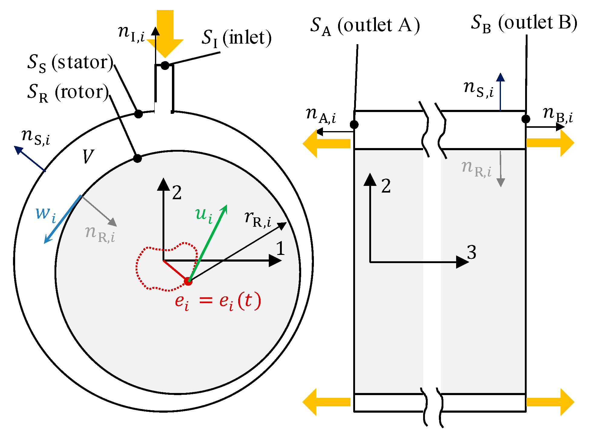
3.1. Explanation of the Convective Term Influence on the Force on the Rotor

In the following steps, the integrals on individual surfaces will be systematically investigated.

3.1.1. Inlet Surface S I

Assuming the orientation of the inlet surface I according to Figure 1, it is clear that the dominant component of the inlet velocity is v 2 . Considering the mean values of density ρ m and velocity v m , i on this surface, it is possible to write the formula for direction 2 as follows:
S I ρ v i v j n j d S I = ρ m v m , 2 v m , 2 + 1 S I = ρ m v m , 2 2 S I .
Obviously, in directions 1 and 3, this integral is close to zero with respect to the minimum magnitudes of the velocities v 1 and v 3 .

3.1.2. Stator Surface S S

The stator surface is assumed to be stationary. In general, in the case of a viscous fluid, the velocity of the fluid on the wall is equal to the velocity of the wall, which is zero in this case. Thus:
S S ρ v i v j n j d S S = 0 .
In the case of a moving stator—for example, when investigating the fluid force on the rotor inside the SFD (e.g., when using floating ring bearings)—the SFD may move, and the integral in Equation (12) will no longer be zero, depending on the type of motion.

3.1.3. Outlet Surfaces S A and S B

Under the assumptions of orientation for S A and S B , according to Figure 1, the surface integrals in direction 1 can be written as follows:
S A ρ v i v j n j d S A + S B ρ v i v j n j d S B = S A ρ v 1 ( v 1 n 1 + v 2 n 2 + v 3 n 3 ) d S A + S B ρ v 1 ( v 1 n 1 + v 2 n 2 + v 3 n 3 ) d S B = S A ρ v 1 v 3 ( 1 ) d S A + S B ρ v 1 v 3 ( + 1 ) d S B ,
since n A , B , 1,2 = 0 , n A , 3 = 1 and n B , 3 = + 1 . Considering the mean values of the outlet velocities at the outlet surfaces, this yields v A , 3 = v m , A , 3 and v B , 3 = + v m , B , 3 . Equation (13) then for i = 1 takes the following form:
S A ρ v i v j n j d S A + S B ρ v i v j n j d S B = + v m , A , 3 S A ρ v 1 d S A + v m , B , 3 S B ρ v 1 d S B = 2 v m , A , 3 S A ρ v 1 d S A
by considering symmetry, that is, the validity of the formula v m , A , 3 = v m , B , 3 . Thus, the result represented by Equation (14) should be understood that if the fluid has a non-zero velocity component v 1 at the outlet, then the integral on the right-hand side of Equation (14) is non-zero. It should be noted, however, that in the case where symmetry does not hold, Equation (13) holds. The effect of density must also be considered. If the density distribution on the outlet surface is not constant, the effect of the non-zero velocity component v 1 may be affected. Notably, when the flow field on the outlet surface is rotating, if there is a perfectly periodic flow with constant density, then the integral S A v 1 d S A is zero. Analogous relations hold for the orthogonal direction 2, according to Figure 1. For example, in Tichy’s [35] work, where the transient CCO motion of the SFD was investigated without considering cavitation, the effect of the outflow velocity was quantified based on the leakage coefficient, which was actually a representation of Equation (13).

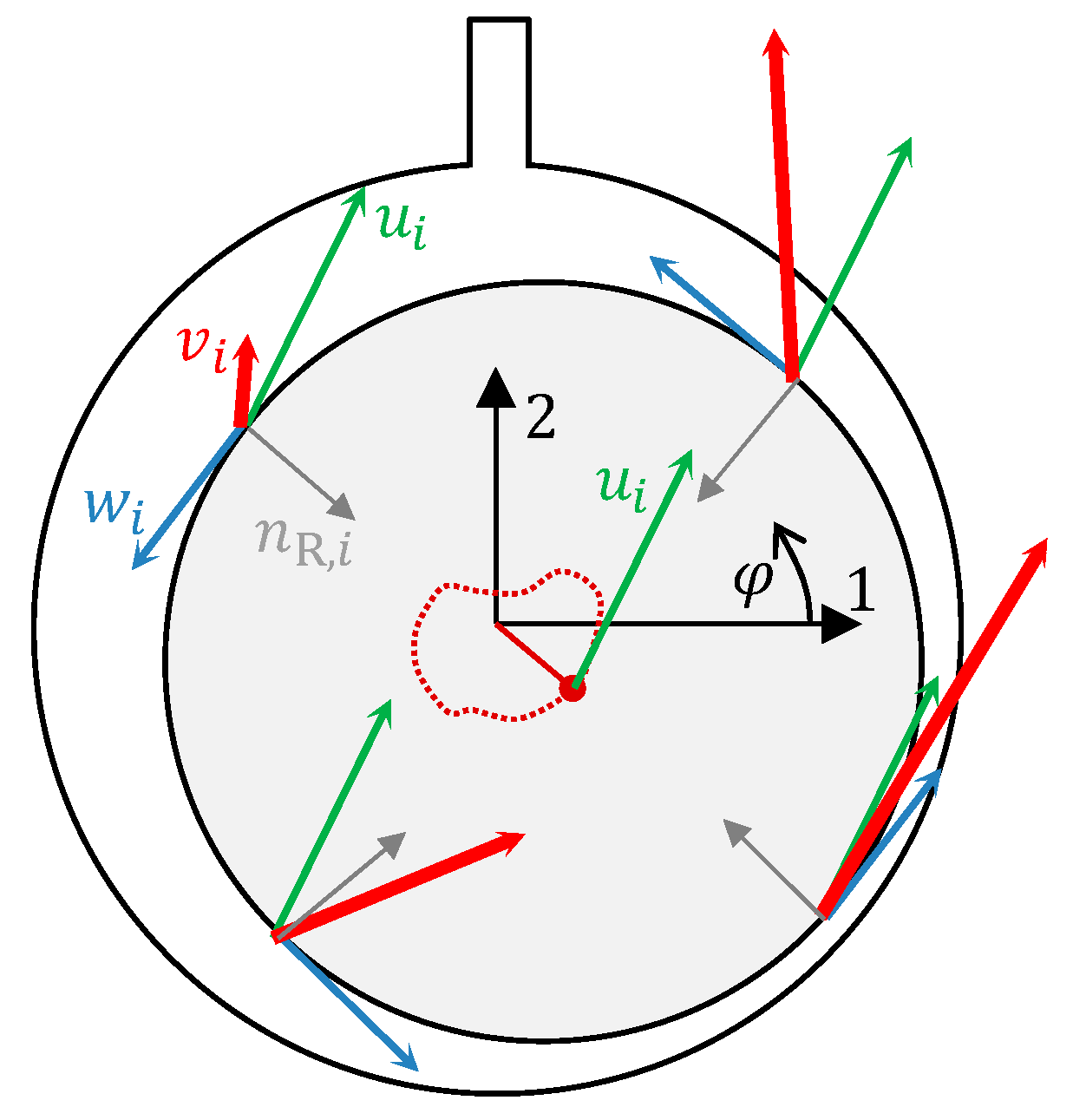
3.1.4. Rotor Surface R

As mentioned, a general rotor motion is considered in which the rotor centre moves and the rotor surface rotates simultaneously around its centre. Thus, it is necessary to investigate the influence of the integral S R ρ v i v j n j d S R , which, with respect to Equation (6), can be expanded as follows:
S R ρ v i v j n j d S R = S R ρ u i + w i u j + w j n j d S R = S R ρ u i u j n j d S R + S R ρ u i w j n j d S R + S R ρ w i u j n j d S R + S R ρ w i w j n j d S R .
The surface integral of the convective term on the rotor performing the compound motion described above can therefore be decomposed as the sum of four surface integrals. At this point, it should be considered that at the rotor surface, the velocities u i and w i are both non-zero during the above motion; thus, in the case of a flow with non-constant density over the rotor surface, none of the four integrals of the right-hand side of Equation (15) are zero.
However, in the case of a constant density flow, the situation is different, as density ρ can be placed before the integral. For illustrative purposes, the velocity components of the rotor motion, consisting of the general planar trajectory of its centre and the rotation of the rotor surface about its centre, are plotted in Figure 2. The resulting velocity vector v i is different at each point on the rotor surface.
Furthermore, the following must be taken into account:
  • The velocity vector of the rotor centre u i is the same at each point of the rotor surface; that is, it can be placed before the integral.
  • At each point, the circumferential velocity vector on the rotor surface w i is perpendicular to the unit normal vector of the rotor surface n R , i . This fact holds for a circular cross-section of the rotor.
Assuming constant density ρ , the surface integral of the convective term on the rotor surface can be written as follows:
S R ρ v i v j n j d S R = ρ u i u j S R n j d S R + ρ u i S R w j n j d S R + ρ u j S R w i n j d S R + ρ S R w i w j n j d S R
The first term on the right-hand side of Equation (16) ρ u i u j S R n j d S R is zero since S R n j d S R = 0 for any closed curve. This conclusion is important because in the case of a non-rotating shaft (i.e., w i = 0 )—for example, in the case of a CCO motion where only the general motion of the rotor centre occurs—the effect of the convective term from the rotor surface on the force on the rotor is zero. However, if the rotor surface is not translational in the axial direction (i.e., if its cross-section is changing in the axial direction), then the term S R n 3 d S R does not have to be zero. It should be stressed once again that this conclusion holds for the case of constant density. In the case of non-constant density—for example, in the case of compressible flow or in the case of cavitation—the first term of the right-hand side of Equation (16) will be of the form u i u j S R ρ n j d S R .
In the second and fourth terms of Equation (16), the expression w j n j represents the dot product of the circumferential velocity vector and the normal vector of the rotor area. In the case of a cylindrical rotor, these vectors are orthogonal to each other at each point on the rotor surface, and their dot product is thus zero. Therefore, the second and fourth integrals of the right-hand side of Equation (16) are zero. Thus, ρ u i S R w j n j d S R = 0 , and ρ S R w i w j n j d S R = 0 . Again, it should be emphasised that in the case of a non-constant density on the rotor surface, this statement does not have to hold.
However, the third term on the right-hand side of Equation (16)—that is, ρ u j S R w i n j d S R —is not zero even in the case of constant density, and its effect needs to be investigated. For further consideration, the following relations are used:
w 1 = ω r R s i n ( φ ) ,   w 2 = ω r R c o s ( φ ) , n 1 = c o s ( φ ) ,   n 2 = s i n ( φ ) .
By substituting them into ρ u j S R w i n j d S R , it is thus possible to write the following for direction 1:
ρ u j S R w i n j d S R = ρ S R w 1 ( n 1 u 1 + n 2 u 2 ) d S R = ρ 0 2 π ω r R s i n ( φ ) c o s ( φ ) u 1 s i n ( φ ) u 2 r R d φ L = ρ ω r R 0 2 π u 1 sin φ cos φ + u 2 s i n 2 φ r R d φ L = ρ u 2 ω r R 2 π L = 1 2 ρ u 2 w S R ,
where w denotes the magnitude of the rotor surface circumferential velocity vector, and L denotes the rotor axial length. By analogy, for direction 2:
ρ u j S R w i n j d S R = ρ S R w 2 ( n 1 u 1 + n 2 u 2 ) d S R = ρ 0 2 π ω r R c o s ( φ ) c o s ( φ ) u 1 s i n ( φ ) u 2 r R d φ L = ρ ω r R 0 2 π u 1 c o s 2 φ u 2 c o s ( φ ) s i n ( φ ) r R d φ L = ρ u 1 ω r R 2 π L = 1 2 ρ u 1 w S R .
Equations (16), (18) and (19) for the constant density case imply that the effect of the convective term on the rotor is zero in the case of a moving non-rotating rotor or a rotating rotor only. However, in the case of compound motion, the influence of the convective term on the rotor surface is non-zero. As seen in the results of Equations (18) and (19), the force in direction 1 depends on the velocity in the perpendicular direction u 2 and the circumferential velocity w . Analogously, the force in direction 2 is dependent on velocity u 1 . It is a force due to Coriolis acceleration; for example, if the rotor rotates about its axis while oscillating only in direction 2, there will be an additional force in direction 1. Again, it should be emphasised that in the case of variable density (cavitation or ideal gas), the effects of the convective forces on the rotor may be significantly different from those presented by Equations (18) and (19) because all four terms in Equation (16) are non-zero. A concise summary of the contributions of each term in Equation (16) is presented in Table 1. Among the considered motion types, only the compound motion, representing the most realistic scenario, produces a non-zero term in Equation (16).
It should also be noted that neglecting the first, second and fourth terms in Equation (16) was not based on the assumption of a particular trajectory of the rotor centre or the assumption of turbulent or laminar flow. It can be concluded that in the case of an arbitrary rotor centre trajectory and with the rotor surface rotating simultaneously about its centre and assuming constant density, only the term ρ u j S R w i n j d S R is not zero. However, the form of this term, which is represented by Equations (18) and (19), is valid only for thin layers. This is because the angle φ defining the rotor surface point used can be considered the same independently of a small eccentricity e i with respect to r R ; that is, φ is the same in the coordinate system associated with the stator and the moving rotor if e i r R .

3.2. Notes on the Influence of the Convective Term

To understand the observations of the influence of the convective term made by individual researchers, the following problem will be considered:
  • The lubrication layer includes two or more rotationally symmetrical inlets S I .
  • The fluid has a constant density and viscosity.
  • The rotor performs the CCO movement or oscillates in the radial direction and does not rotate.
  • The outlet velocity has either a non-zero only axial velocity component at each point of the outlet surface, or the outlet velocity is rotationally periodic.
Based on these assumptions, the contribution of the convective term surface integrals of S I , S R , S S , S A , S B is zero. However, neglecting the convective term in the momentum conservation law will result in a distribution of velocity and pressure vectors in the lubrication layer different from that if the convective term is considered. Zero area integrals of the convective term mean that the presence of the convective term in the equations does not affect the resulting force on the rotor, but the spatial distribution of the velocity and pressure vectors is affected by the presence of the convective term. The convective term must be in balance with the other terms of the Navier–Stokes equation, as seen in Equation (4). It should therefore be mentioned that the force acting on the rotor arises from the pressure and viscous forces (see Equations (8) and (9)). Under these assumptions, the presence of the convective term therefore affects the distribution of velocities and pressure in the lubrication layer in such a way that the sum of their surface integrals—that is, the sum of pressure forces and viscous forces—is the same as in the case of neglecting the convective term. This fact leads to the conclusion that from the point of view of rigorous evaluation of the acting forces with the aim of verifying the influence of the convective term, frictional forces must also be considered.
The observed influence of the convective term can thus be understood in the works of individual researchers as a consequence of several possible phenomena:
  • The effect of non-constant density due to cavitation or fluid compressibility.
  • The influence of the outlet velocity whose surface integral in the radial direction is not zero.
  • The influence of inlet velocity.
  • The inborn character of numerical methods in nonlinear systems of equations.
The effect of cavitation is obvious with respect to Equation (16) since the variable density can introduce strong nonlinearity. However, in cases where cavitation is not considered and a constant density is considered, the influence of the convective term cannot be attributed to the rotor motion unless the motion is compound. This fact was observed, for example, in Brindley’s [63] work, although the inertial term was considered by introducing corrections to the equations. The inlet and outlet velocities represent the expected way in which the convective term affects the applied force. However, it should be noted that in lubrication layer solution methods where the variable magnitude of the velocity components at the outlet surfaces perpendicular to the rotor are not considered, the influence of the convective term must also be zero.
The possible influence of numerical methods in the case of solving nonlinear equations cannot be underestimated either. In the field of nonlinear dynamical systems, it is well known that even the simplest nonlinear equations can exhibit deterministic chaos. For example, the well-known logistic equation y i + 1 = k y i ( 1 y i ) behaves stably for the parameter range k 0 ; 3 since the value of y i + 1 converges to a single solution for increasing i independently of the initial value of y 0 ; 1 . However, when k > 3 , oscillations and bifurcations mostly occur. Then, the value of y i + 1 does not converge to a single number and exhibits deterministic chaos from the value of the parameter k = 3.56995 . The complex behaviour of very simple equations was presented in May’s [64] famous paper, which illustrated that even very simple systems of equations can exhibit very unpredictable behaviour, although they are deterministic systems. These facts have been investigated in detail in many other works, and it should be pointed out that a key element leading to the chaotic behaviour of the solutions of some systems of equations is their nonlinearity.
This analogy may explain why some papers show a relatively strong influence of the numerical method on the resulting force on the rotor when using different numerical methods. For example, the aforementioned momentum or energy approximation method and perturbation method consider a certain velocity profile in the lubrication layer, which is further replaced by a certain integral value; however, the assumption of the velocity profile is fundamental. The resulting velocity profile is the result of the defined rotor kinematic conditions. In light of the behaviour of the logistic equation, the solution of the momentum conservation law containing a nonlinear convective term when considering many additional assumptions, in addition to the prospective abrupt change in density due to cavitation, appears to be strongly conditioned by the choice of numerical method.
In the context of the possible existence of deterministic chaos in solutions of the Navier–Stokes equations, it is worth mentioning Hall and Papageorgiou’s [65] important work, which builds on Stuart et al.’s [66] findings. Hall and Papageorgiou [65] showed that in the case of a fluid bounded by two parallel walls, one of which oscillates periodically in the normal direction, the values of the relative amplitude of the wall motion and its frequency can be used to determine the state where the instability of the flow field occurs and, hence, the onset of chaos. In this paper, a practical demonstration was given that in the case of a hydrodynamic bearing wall motion frequency f = 1000   H z and a paraffin base oil viscosity corresponding to 100   ° C , a loss of symmetry occurs at an amplitude of 0.14   m m and the onset of chaos at 0.3   m m . Thus, it is obvious that the lubrication layer solution exhibits chaotic behaviour under certain conditions.

4. Discussion

To better understand the effects of hydrodynamic forces on the rotor surface, it is useful to perform further mathematical modifications. The rotor will be considered to perform a motion of the rotor centre with velocity u i = u i ( t ) and rotating at a circumferential velocity w i . The fluid is assumed to have a constant density and a constant dynamic viscosity μ . In addition, a small radial clearance c r R between the rotor and the stator is considered. Based on these assumptions, Equation (4) can be written as follows.
ρ v i t + ρ v i x j v j = p x i + μ 2 v i x j x j ,  
and for its volume integral, the following holds:
ρ V x j v j t x i d V + ρ V x j v i v j d V = V p x i d V + μ V x j v i x j d V ,
where the first term on the left-hand side of the equation is based on the continuity equation for incompressible flow v j / x j = 0 and the relation x i / x j = δ i j [67]. Using these relations, the volume integral of the temporal term can be converted to an area integral, which implies that:
ρ Φ v j t x i n j d Φ + ρ Φ v i v j n j d Φ + Φ p n i d Φ μ Φ v i x j   n j d Φ = 0 .
With respect to Equations (8) and (9), the force acting on the rotor surface can be written as follows:
F p , i + F f , i = ρ S R v j t x i n j d S R ρ S S v j t x i n j d S S ρ S I v j t x i n j d S I ρ S A v j t x i n j d S A ρ S B v j t x i n j d S B ρ S R v i v j n j d S R ρ S S v i v j n j d S S ρ S I v i v j n j d S I ρ S A v i v j n j d S A ρ S B v i v j n j d S B S S p n i d S S S I p n i d S I S A p n i d S A S B p n i d S B + μ S S v i x j   n j d S S + μ S I v i x j   n j d S I + μ S A v i x j   n j d S A + μ S B v i x j   n j d S B .
Equation (23) represents an expanded form of force equilibrium. In addition, the following assumptions will be considered for the sake of clarity:
  • Non-moving stator S S : v i = 0 .
  • Small influence of the temporal term on inlet surface S I and outlet surfaces S A and S B .
  • Small influence of the viscous and pressure terms on inlet surface S I and outlet surfaces S A and S B .
  • Small influence of the convective term on inlet surface S I and outlet surfaces S A and S B .
Based on these assumptions, Equation (23) is reduced to the following form:
F p , i + F f , i = ρ S R v j t x i n j d S R S S p n i d S S + μ S S v i x j   n j d S S .
Since a thin lubrication layer is considered, it can be assumed that p / r = 0 . And since r R + c = r S , it is possible to write the following:
S S p n i d S S = 0 2 π p n i r S d φ L = 0 2 π p n S , i r R d φ L + 0 2 π p n S , i c d φ L = 0 2 π p n R , i r R d φ L F p , i 0 2 π p n R , i c d φ L = c r R F p , i F p , i c r R F p , i .
In Equation (25), as the stator normal vector is opposite to the rotor normal vector for any angle φ , n R , i = n S , i was used. Analogously, this procedure can be carried out for the viscous term:
μ S S v i x j n j d S S = μ 0 2 π v i x j n j r S d φ L = μ 0 2 π v i x j n S , j r R d φ L + μ 0 2 π v i x j n S , j c d φ L = μ 0 2 π v i x j n R , j r R d φ L F f , i μ 0 2 π v i x j n R , j c d φ L =   c r R F f , i F f , i + c r R F f , i   .
Equation (24) can then be stated as follows:
F p , i + F f , i = r R c ρ S R v j t x i n j d S R o r S R p n i d S R μ S R v i x j n j d S R = r R c ρ S R v j t x i n j d S R ,
which expresses that the sum of the pressure and viscous forces on the rotor surface must be in equilibrium with the force due to the temporal term on the rotor. In the case of the periodic motion of the rotor within the lubrication layer, its position can be written as follows:
e R , i = k 0 , i s i n ( Ω R , i t + φ 0 , i ) ,
where k 0 , i is a maximum amplitude, Ω R , i is an angular frequency of the periodic motion of the rotor centre, and φ 0 , i is a phase shift. Thus, the instantaneous rotor surface velocity is:
v R , i = d e R , i d t = k 0 , i Ω R , i c o s ( Ω R , i t + φ 0 , i ) ,
and the time derivative of velocity can be written as follows:
d v R , i d t = d 2 e R , i d t 2 = k 0 , i Ω R , i 2 s i n Ω R , i t + φ 0 , i .
Equations (29) and (30) provide insight into the influence of the individual terms in the motion of the rotor centre with arbitrary trajectory e R , i = e R , i ( t ) . For the viscous term in Equation (27), it holds that:
F f ,   m a x ,   i = μ S R v R , i x j n j d S R = μ x j S R k 0 , i Ω R , i c o s ( Ω R , i t + φ 0 , i ) n j d S R   F f ,   m a x ,   i ~   μ Ω R , i .
The frequency dependence of the pressure forces in Equation (27) can be presented based on the idea of an inviscid fluid, where the viscous term is zero, and then:
F p , m a x , i = S R p n i d S R = r R c ρ S R d v R , j d t x i n j d S R = r R c ρ S R k 0 , i Ω R , i 2 s i n Ω R , i t + φ 0 , i x i n j d S R F p , m a x , i   ~   ρ Ω R , i 2 .
Based on Relations (31) and (32), it can be stated that in the case of high fluid viscosity and low density, the maximum force on the rotor increases linearly with the frequency of periodic rotor centre motion. This was already observed by Han and Rogers [29] based on numerical analyses, but they did not justify this dependence in their paper, and it was presented there as an observation only. Nevertheless, in the case of high density and very low viscosity, the maximum fluid force on the rotor increases quadratically with the frequency of the rotor centre motion. In the case where neither the viscous term nor the temporal term dominates, it can be assumed that the dependence of the maximum fluid force on the rotor centre frequency is between linear and quadratic.

5. Conclusions

Based on the analysis of the Navier–Stokes equation, the effect of the convective term on the force acting on the rotor performing a general motion relative to the stator has been demonstrated. In the case where the fluid has a constant density, the influence of the inlet and outlet pressures and velocities is not considered, and the centre of the non-rotating rotor performs a general motion, the additional force effect on the rotor due to the convective term is zero. Considering that the convective term in the equations in this case has zero effect on the resulting force on the rotor, the velocity and pressure field in the lubrication layer will be different.
The results presented here have shown that the sum of the viscous and pressure forces on the rotor remains the same as in the case of not considering the convective term; that is, the convective term does not affect the sum of the frictional and viscous forces acting on the rotor. If the force on the rotor is evaluated only on the basis of the pressure forces and not as a sum of the pressure and viscous forces, then the effect of the convective term can be observed precisely because of the influence of the pressure field.
The possible ways in which considering the convective term in the equations describing hydrodynamic lubrication can affect the force on the rotor are as follows:
  • Non-constant density (compressible fluid or cavitation).
  • Non-zero area integral of the convective term on all inlet and outlet surfaces.
  • Simultaneous rotation of the rotor surface and non-zero velocity of its centre.
The convective term is a nonlinear term. This property can cause the unpredictability of results when solving differential equations. Thus, the solutions of nonlinear differential equations may exhibit different solutions for various numerical methods since the solutions of the Navier–Stokes equation may exhibit chaotic behaviour even in the case of the thin lubrication layer problem. Certainly, the variability in the researchers’ conclusions presented in this paper cannot be generalised as a consequence of the sensitivity of the equations to the numerical parameters of a solver due to introducing the nonlinear convective term; however, this phenomenon cannot be ignored.
Thus, a simple approach can be proposed to develop computational codes to determine the force on rotor during transient motion when considering a convective term:
  • The computational model should first be tested under simplified conditions:
    • Constant fluid density.
    • Rotor CCO motion or oscillations in one direction without rotation.
    • Stationary stator.
    • No axial outflow.
    • No radial inflow.
    • No convective term.
Under these assumptions, only the temporal, pressure, and viscous terms should be retained.
2.
The force calculation must incorporate both the pressure field and the velocity field, e.g., both Equations (8) and (9).
3.
The convective term should be introduced into the model. If the implementation is correct, the computed force should remain unchanged.
It has also been shown here that in the case of periodic rotor centre motion (e.g., CCO), a linear dependence of the applied force on the fluid viscosity and rotor frequency can be expected under the assumption of low fluid density. Conversely, for a low-viscosity fluid, the dependence of the applied force on the rotor frequency is quadratic and linearly dependent on the fluid density.
The findings presented here provide insight into the presence of a convective term in the equations for solving hydrodynamic lubrication. The clarification presented here is a qualitative analysis, based on which the force effect of the convective term on the rotor can be estimated and explained. The implications of this theoretical study are thus valid for a broad spectrum of rotors.

Author Contributions

J.V.: formal analysis, investigation, and writing—original draft preparation. P.N.: formal analysis, supervision. All authors have read and agreed to the published version of the manuscript.

Funding

This publication was supported by the project “Innovative Technologies for Smart Low Emission Mobilities”, funded as project No. CZ.02.01.01/00/23_020/0008528 by Programme Johannes Amos Comenius, call Intersectoral cooperation.

Data Availability Statement

The original contributions presented in this study are included in this article. Further inquiries can be directed to the corresponding author.

Conflicts of Interest

The authors declare no conflicts of interest.

Abbreviations

The following abbreviations are used in this manuscript:
Nomenclature
c radial clearance
F force
e i rotor centre position vector
f frequency of periodic motion
k non-dimensional parameter
k 0 , i maximum amplitude of periodic motion
x i general position vector
t time
p pressure
L bearing length
S surface
n i normal vector
Vvolume
r radius
y non-dimensional variable
u i rotor centre velocity vector
v i absolute velocity vector
w i rotating velocity vector
Greek letters
δ i j Kronecker‘s delta
ε i j k Levi-Civita tensor
σ i j Cauchy stress tensor
τ i j viscous stress tensor
μ dynamic viscosity
λ bulk viscosity
ρ fluid density
Φ general surface
φ polar angle
ω i angular velocity vector
Ω i angular velocity of periodic motion
Subscripts
f friction
m mean
m a x maximum
p pressure
i , j number indices
I inlet surface I
A outlet surface A
B outlet surface B
R rotor
S stator
Abbreviations
SFDsqueeze film damper
CCOcircular centred orbit
CFDcomputational fluid dynamics

References

  1. Reynolds, O. On the theory of lubrication and its application to Mr. Beauchamp tower’s experiments, including an experimental determination of the viscosity of olive oil. Phil. Trans. R. Soc. 1886, 177, 157–234. [Google Scholar]
  2. Sommerfeld, A. Zur hydrodynamische theorie derschmiermittelreibung. Zeit. Math. Phys. 1904, 50, 97–155. [Google Scholar]
  3. Gümbel, L. Das problem der lagerreibung. Mon. Berl. Bezirksverein. V.D.I. 1914, 5, 87–104+109–120. [Google Scholar]
  4. Temperley, H.N.V.; Dowson, D.; Godet, M.; Taylor, C.M. The tensile strength of liquids. Cavitation and related phenomena in lubrication. In Proceedings of the 1st Leeds-Lyon Symposium on Tribology, London, UK, 14–17 September 1974; Mechanical Engineering Publications Ltd.: London, UK, 1974; pp. 11–14. [Google Scholar]
  5. Temperley, H.N.V.; Chambers, L.G. The behaviour of water under hydrostatic tension. Part I. Proc. Phys. Soc. 1946, 58, 420–436. [Google Scholar] [CrossRef]
  6. Temperley, H.N.V. The behaviour of water under hydrostatic tension. Part II. Proc. Phys. Soc. 1946, 58, 436–443. [Google Scholar] [CrossRef]
  7. Braun, M.J.; Hannon, W.M. Cavitation formation and modelling for fluid film bearings: A review. Proc. Inst. Mech. Eng. Part J J. Eng. Tribol. 2010, 224, 839–863. [Google Scholar] [CrossRef]
  8. Floberg, L. On the tensile strength of liquids. In Transactions of Machine Elements Division; Lund Engineering University: Lund, Sweden, 1973; pp. 1–13. [Google Scholar]
  9. Franc, J.P. The Rayleigh-Plesset equation: A simple and powerful tool to understand various aspects of cavitation. In Fluid Dynamics of Cavitation and Cavitating Turbopumps; CISM International Centre for Mechanical Sciences; Springer: Vienna, Austria, 2007; Volume 496, pp. 1–41. [Google Scholar]
  10. Brennen, C. A numerical solution of axisymmetric cavity flows. J. Fluid Mech. 1969, 37, 671–688. [Google Scholar] [CrossRef]
  11. Taylor, G.I. Stability of a Viscous Liquid Contained between Two Rotating Cylinders. Philos. Trans. R. Soc. Lond. Ser. A 1923, 223, 289–343. [Google Scholar]
  12. Childs, P.R.N. Rotating Cylinders, Annuli, and Spheres. In Rotating Flow; Butterworth-Heinemann: Oxford, UK, 2011; pp. 177–247. [Google Scholar] [CrossRef]
  13. Donnelly, R.J.; Simon, N.J. An empirical torque relation for supercritical flow between rotating cylinders. J. Fluid Mech. 1960, 7, 401–418. [Google Scholar] [CrossRef]
  14. Schwarz, K.W.; Springett, B.E.; Donnelly, R.J. Modes of instability in spiral flow between rotating cylinders. J. Fluid Mech. 1964, 20, 281–289. [Google Scholar] [CrossRef]
  15. Coles, D. Transition in circular Couette flow. J. Fluid Mech. 1965, 21, 385–425. [Google Scholar] [CrossRef]
  16. Snyder, H.A. Waveforms in rotating Couette flow. Int. J. Non-Linear Mech. 1970, 5, 659–685. [Google Scholar] [CrossRef]
  17. Fenstermacher, P.R.; Swinney, H.L.; Gollub, J.P. Dynamical instabilities and the transition to chaotic Taylor vortex flow. J. Fluid Mech. 1979, 94, 103–129. [Google Scholar] [CrossRef]
  18. Andereck, C.D.; Liu, S.S.; Swinney, H.L. Flow regimes in a circular Couette system with independently rotating cylinders. J. Fluid Mech. 1986, 164, 155–183. [Google Scholar] [CrossRef]
  19. Brandstater, A.; Swinney, H.L. Strange attractors in weakly turbulent Couette-Taylor flow. Phys. Rev. A 1987, 35, 2207–2220. [Google Scholar] [CrossRef] [PubMed]
  20. Smith, D.M. Journal Bearing Dynamic Characteristics—Effect of Inertia of Lubricant. Proc. Inst. Mech. Eng. 1964, 179, 37–44. [Google Scholar] [CrossRef]
  21. San Andres, L.A.; Vance, J.M. Effect of Fluid Inertia on Squeeze-Film Damper Forces for Small-Amplitude Circular-Centered Motions. ASLE Trans. 1987, 30, 63–68. [Google Scholar] [CrossRef]
  22. Modest, M.F.; Tichy, J.A. Squeeze Film Flow in Arbitrarily Shaped Journal Bearings Subject to Oscillations. J. Lubr. Technol. 1978, 100, 323–329. [Google Scholar] [CrossRef]
  23. Szeri, A.Z.; Raimondi, A.A.; Giron-Duarte, A. Linear Force Coefficients for Squeeze-Film Dampers. J. Lubr. Technol. 1983, 105, 326–334. [Google Scholar] [CrossRef]
  24. Tichy, J.; Bou-Saïd, B. Hydrodynamic Lubrication and Bearing Behavior with Impulsive Loads. Tribol. Trans. 1991, 34, 505–512. [Google Scholar] [CrossRef]
  25. Constantinescu, V.N. On the Influence of Inertia Forces in Turbulent and Laminar Self-Acting Films. J. Lubr. Technol. 1970, 92, 473–480. [Google Scholar] [CrossRef]
  26. Osterle, J.F.; Chou, Y.T.; Saibel, E.A. The Effect of Lubricant Inertia in Journal-Bearing Lubrication. J. Appl. Mech. 1957, 24, 494–496. [Google Scholar] [CrossRef]
  27. Reinhardt, E.; Lund, J.W. The Influence of Fluid Inertia on the Dynamic Properties of Journal Bearings. J. Lubr. Technol. 1975, 97, 159–165. [Google Scholar] [CrossRef]
  28. Han, Y.; Rogers, R.J. Nonlinear fluid forces in cylindrical squeeze films. Part I: Short and long lengths. J. Fluids Struct. 2001, 15, 151–169. [Google Scholar] [CrossRef]
  29. Han, Y.; Rogers, R.J. Nonlinear fluid forces in cylindrical squeeze films. Part II: Finite length. J. Fluids Struct. 2001, 15, 171–206. [Google Scholar] [CrossRef]
  30. Zhang, J.; Ellis, J.; Roberts, J.B. Observations on the Nonlinear Fluid Forces in Short Cylindrical Squeeze Film Dampers. J. Tribol. 1993, 115, 692–698. [Google Scholar] [CrossRef]
  31. El-Shafei, A.; Crandall, S.M. Fluid Inertia Forces in Squeeze Film Dampers. In Proceedings of the 13th Biennial Conference on Mechanical Vibration and Noise: Rotating Machinery and Vehicle Dynamics, Miami, FL, USA, 22–25 September 1991; ASME: New York, NY, USA, 1991; pp. 219–228. [Google Scholar] [CrossRef]
  32. Crandall, S.H.; El-Shafei, A. Momentum and Energy Approximations for Elementary Squeeze-Film Damper Flows. J. Appl. Mech. 1993, 60, 728–736. [Google Scholar] [CrossRef]
  33. San Andres, L.A.; Vance, J.M. Effects of Fluid Inertia on Finite-Length Squeeze-Film Dampers. ASLE Trans. 1987, 30, 384–393. [Google Scholar] [CrossRef]
  34. San Andrés, L.; Vance, J.M. Effects of Fluid Inertia and Turbulence on the Force Coefficients for Squeeze Film Dampers. J. Eng. Gas Turbines Power 1986, 108, 332–339. [Google Scholar] [CrossRef]
  35. Tichy, J.A. A Study of the Effect of Fluid Inertia and End Leakage in the Finite Squeeze Film Damper. J. Tribol. 1987, 109, 54–59. [Google Scholar] [CrossRef]
  36. Hamzehlouia, S.; Behdinan, K. A Study of Lubricant Inertia Effects for Squeeze Film Dampers Incorporated into High-Speed Turbomachinery. Lubricants 2017, 5, 43. [Google Scholar] [CrossRef]
  37. Hamzehlouia, S.; Behdinan, K. Squeeze Film Dampers Executing Small Amplitude Circular-Centered Orbits in High-Speed Turbomachinery. Int. J. Aerosp. Eng. 2016, 2016, 5127096. [Google Scholar] [CrossRef]
  38. Bonello, P.; Brennan, M.J.; Holmes, R. Non-linear modelling of rotor dynamic systems with squeeze film dampers—An efficient integrated approach. J. Sound Vib. 2002, 249, 743–773. [Google Scholar] [CrossRef]
  39. Hamzehlouia, S.; Behdinan, K. Squeeze film dampers supporting high-speed rotors: Rotordynamics. Proc. Inst. Mech. Eng. Part J J. Eng. Tribol. 2021, 235, 495–508. [Google Scholar] [CrossRef]
  40. Shen, G.; Xiao, Z.; Zhang, W.; Zheng, T. Nonlinear Behavior Analysis of a Rotor Supported on Fluid-Film Bearings. J. Vib. Acoust. 2006, 128, 35–40. [Google Scholar] [CrossRef]
  41. Von Osmanski, S.; Santos, I.F. Gas foil bearings with radial injection: Multi-domain stability analysis and unbalance response. J. Sound Vib. 2021, 508, 116177. [Google Scholar] [CrossRef]
  42. Novotný, P.; Jonák, M.; Vacula, J. Evolutionary Optimisation of the Thrust Bearing Considering Multiple Operating Conditions in Turbomachinery. Int. J. Mech. Sci. 2021, 195, 106240. [Google Scholar] [CrossRef]
  43. Zhang, J.; Han, D.; Xie, Z.; Huang, C.; Rao, Z.; Song, M.; Su, Z. Nonlinear behaviors analysis of high-speed rotor system supported by aerostatic bearings. Tribol. Int. 2022, 170, 107111. [Google Scholar] [CrossRef]
  44. Manshoor, B.; Jaat, M.; Izzuddin, Z.; Amir, K. CFD Analysis of Thin Film Lubricated Journal Bearing. Procedia Eng. 2013, 68, 56–62. [Google Scholar] [CrossRef]
  45. Sahu, M.; Giri, A.K.; Das, A. Thermohydrodynamic Analysis of a Journal Bearing Using CFD as a Tool. Int. J. Sci. Res. Publ. 2012, 2, 1–7. [Google Scholar]
  46. Shahmohamadi, H.; Rahmani, R.; Rahnejat, H.; Garner, C.P.; Dowson, D. Big End Bearing Losses with Thermal Cavitation Flow Under Cylinder Deactivation. Tribol. Lett. 2015, 57, 2. [Google Scholar] [CrossRef]
  47. Song, Y.; Gu, C.; Ren, X. Development and validation of a gaseous cavitation model for hydrodynamic lubrication. Proc. Inst. Mech. Eng. Part J J. Eng. Tribol. 2015, 229, 1227–1238. [Google Scholar] [CrossRef]
  48. Ding, A.; Xiao, Y. Numerical Investigation for Characteristics and Oil-Air Distributions of Oil Film in a Tilting-Pad Journal Bearing. In Turbo Expo: Power for Land, Sea, and Air; Volume 7B: Structures and Dynamics; ASME: New York, NY, USA, 2018; Volume 7B, pp. 1–11. [Google Scholar] [CrossRef]
  49. Ding, A.; Ren, X.; Li, X.; Gu, C. A new gaseous cavitation model in a tilting-pad journal bearing. Sci. Prog. 2021, 104, 1–19. [Google Scholar] [CrossRef]
  50. Wang, L.; Liu, Z.; Yuan, G.; Wei, Y. Combined Influence of Noncondensable Gas Mass Fraction and Mathematical Model on Cavitation Performance of Bearing. Int. J. Rotating Mach. 2020, 2020, 8409231. [Google Scholar] [CrossRef]
  51. Ochiai, M.; Sakai, F.; Hashimoto, H. Reproducibility of Gaseous Phase Area on Journal Bearing Utilizing Multi-Phase Flow CFD Analysis under Flooded and Starved Lubrication Conditions. Lubricants 2019, 7, 74. [Google Scholar] [CrossRef]
  52. Rasep, Z.; Yazid, M.N.A.W.M.; Samion, S. A study of cavitation effect in a journal bearing using CFD: A case study of engine oil, palm oil and water. J. Tribol. 2021, 28, 48–62. [Google Scholar]
  53. Geller, M.; Schemmann, C.; Kluck, N. Simulation of radial journal bearings using the FSI approach and a multi-phase model with integrated cavitation. Prog. Comput. Fluid Dyn. 2014, 14, 14–23. [Google Scholar] [CrossRef]
  54. Ramdhani, S.; Haryanto, I.; Tauviqirrahman, M. 3D simulation of the lubrication film in journal bearing using Fluid-Structure Interaction (FSI). J. Phys. Conf. Ser. 2018, 1090, 012025. [Google Scholar] [CrossRef]
  55. Dhande, D.Y.; Pande, D.W. Multiphase flow analysis of hydrodynamic journal bearing using CFD coupled Fluid Structure Interaction considering cavitation. J. King Saud Univ. Eng. Sci. 2018, 30, 345–354. [Google Scholar] [CrossRef]
  56. Wang, Y.; Xiao, Y.B. Development of an evaluation method of floating ring bearings by CFD with mesh motion. IOP Conf. Ser. Earth Environ. Sci. 2018, 163, 012080. [Google Scholar] [CrossRef]
  57. Song, Y.; Gu, C. Development and Validation of a Three-Dimensional Computational Fluid Dynamics Analysis for Journal Bearings Considering Cavitation and Conjugate Heat Transfer. J. Eng. Gas Turbines Power 2015, 137, 122502. [Google Scholar] [CrossRef]
  58. Xing, C.; Braun, M.J.; Li, H. Damping and added mass coefficients for a squeeze film damper using the full 3-D Navier-Stokes equation. Tribol. Int. 2010, 43, 654–666. [Google Scholar] [CrossRef]
  59. Shi, X.; Ni, T. Effects of groove textures on fully lubricated sliding with cavitation. Tribol. Int. 2011, 44, 2022–2028. [Google Scholar] [CrossRef]
  60. Nie, T.; Yang, K.; Zhou, L.; Wu, X.; Wang, Y. CFD analysis of load capacity of journal bearing with surface texture. Energy Rep. 2022, 8, 327–334. [Google Scholar] [CrossRef]
  61. Gengyuan, G.; Zhongwei, Y.; Dan, J.; Xiuli, Z. CFD analysis of load-carrying capacity of hydrodynamic lubrication on a water-lubricated journal bearing. Ind. Lubr. Tribol. 2015, 67, 30–37. [Google Scholar] [CrossRef]
  62. Pérez-Viguera, D.; Colín-Ocampo, J.; Blanco-Ortega, A.; Campos-Amézcua, R.; Mazón-Valadez, C.; Rodríguez-Reyes, V.I.; Landa-Damas, S.J. Fluid Film Bearings and CFD Modeling: A Review. Machines 2023, 11, 1030. [Google Scholar] [CrossRef]
  63. Brindley, J.; Elliott, L.; McKay, J.T. Flow in a Whirling Rotor Bearing. J. Appl. Mech. 1979, 46, 767–771. [Google Scholar] [CrossRef]
  64. May, R.M. Simple mathematical models with very complicated dynamics. Nature 1976, 261, 459–467. [Google Scholar] [CrossRef]
  65. Hall, P.; Papageorgiou, D.T. The onset of chaos in a class of Navier-Stokes solutions. J. Fluid Mech. 1999, 393, 59–87. [Google Scholar] [CrossRef]
  66. Stuart, J.T.; DiPrima, R.C.; Eagles, P.M.; Davey, A. On the instability of the flow in a squeeze lubrication film. Proc. R. Soc. Lond. Ser. A Math. Phys. Sci. 1990, 430, 347–375. [Google Scholar] [CrossRef]
  67. Fialová, S.; Pochylý, F.; Šedivý, D.; Dančová, P.; Novosad, J. A new form of equation for force determination based on Navier-Stokes equations. EPJ Web Conf. 2019, 213, 02018. [Google Scholar] [CrossRef]
Figure 1. Rotor ( R ) performing compound motion inside the stator ( S ) . The rotor centre follows general trajectory e i with velocity u i .
Lubricants 13 00293 g001
Figure 2. Distribution of velocity components on the rotor surface during compound rotor motion, where u i is the velocity of the rotor centre (e.g., instantaneous velocity of CCO motion), w i is the circumferential velocity of the rotor surface (e.g., the rotor is rotating around its axis), and v i is the resulting absolute velocity (e.g., the sum of u i and w i ).
Lubricants 13 00293 g002
Table 1. Influence of the individual terms in Equation (16) assuming constant density. In contrast, for variable density conditions, such as cavitation or an ideal gas, all four terms contribute (i.e., are non-zero) for any type of motion since the density is included within the integral.
Type
of Motion
ρ u i u j S R n j d S R ρ u i S R w j n j d S R ρ u j S R w i n j d S R ρ S R w i w j n j d S R
Rotation = 0 = 0 = 0 = 0
CCO = 0 = 0 = 0 = 0
Compound = 0 = 0 0 = 0
Disclaimer/Publisher’s Note: The statements, opinions and data contained in all publications are solely those of the individual author(s) and contributor(s) and not of MDPI and/or the editor(s). MDPI and/or the editor(s) disclaim responsibility for any injury to people or property resulting from any ideas, methods, instructions or products referred to in the content.

