Abstract
The proposed tribometer design evaluates lubricants’ lubricating and wear protection properties at the interface of a loaded set of gears. However, this tribometer configuration and testing procedure described in standard ISO 14645-1 does not limit the tribological studies of gear test rigs. This study aimed to design and manufacture a mechanical transmission test rig capable of investigating the tribological condition of a lubricated enclosed gears transmission. The methodology consisted of (i) a definition of the test rig’s requirements; (ii) downsizing the main subassemblies present in the ISO 14635-1 test rig; (iii) designing innovative subassemblies; (iv) an instrumentation and data acquisition system, and (v) setup testing. The proposed system is suitable for evaluating small quantities of lubricants, allowing the analysis of special lubricants such as nanolubricants and ionic liquids in development for gearbox applications. Also, the dynamic loading avoids interruption in the test, providing results closer to working conditions. The experimental test evaluated the lubrication ability of two different base oils simultaneously under various loading conditions. Also, monitoring vibration signals helped identify the appearance of damage on the gear surface.
1. Introduction
Gears are machine elements broadly used in mechanical transmissions to transmit power (torque and angular velocity) between mechanical components [1]. Because of the cyclical loads and the nonconforming contact between their teeth, the gears are subjected to contact fatigue, which is responsible for nucleation and the propagation of cracks across the surface, provoking material detachments in some situations [2]. In addition to the nonconforming surface, the gear teeth contact involves sliding and rolling motions simultaneously, which hinders the reproducibility of the contact in the laboratory environment using traditional tribological rigs [3,4,5]. This tribotest should reproduce similar service conditions to understand the tribological behavior of its components [6].
In order to attend to the demand of testing gears for superficial wear, the ISO 14635-1 [7] presents a test procedure along with a test rig, which should be followed to evaluate the load capacity of oils preventing scuffing on the spur gear’s surfaces. The test rig consists of two gearboxes interconnected by two parallel shafts, one with a load clutch in its section. Each gearbox has a pair of gears and is lubricated by 1.25 L of oil. The complete test procedure is carried out following 12 load stages. Each stage presents interdependent parameters and describes the conditions to which the gears are progressively subjected. These parameters are (i) the torque in the pinion (from 3.3 to 534.5 Nm); (ii) the Hertzian contact stress in the pinion’s teeth (from 146 to 1841 MPa); and (iii) the total work transmitted by the gears up to the end of the load stage (from 0.684 to 497.16 MJ). It is highlighted that the realized work is the product of the transmitted torque and the cycles’ numbers per load stage, which is limited to 2.17 × 10⁴ cycles (1.36 × 10⁵ rad) of the motor shaft. Moreover, the load application is performed by a lever arm, which applies the torque to the clutch. A critical condition is that the load change can be performed only at the moments between the stages when the motor is halted. Also, after the load stage is completed, the teeth of the pinion are analyzed. When the failure criterion is reached, the test is interrupted. This testing is important for developing environmentally friendly lubricants because their performance must be ensured and classified. Sagraloff et al. [8] investigated the oil-free water emulsion for lubricating a gearbox by tribometer. The results allowed an understanding of which additives are needed to avoid tribological-influenced damage such as sliding wear and scuffing on the surface of gear flanks.
However, the tribological test rigs for mechanical transmission are not limited by ISO 14635-1 [7]. The usage of gear test rigs can be found in several applications such as gear lubrication tests, gear materials tests, gear innovative geometries, or gear stiffness research [9,10]. Although the experimental setups are different, they have a common target, simulating mechanical transmissions’ practical applications, which are worth analyzing.
From the point of view of tribological results, Fernandes et al. [9], Muraro et al. [10], and Meneghetti et al. [11] developed diverse test rigs for the optimization of the gear work features. In order to characterize the fatigue contact in the gears’ teeth, Meneghetti et al. [11] used a twin-disc tribometer to argue that the contact between two cylinders can simulate the teeth contact. Fernandes et al. [9], in turn, set up a test rig to analyze the power loss in a mechanical transmission between a wind turbine hub and its electric power generator using a real-sized gearbox multiplier from an 850 kW wind turbine. Lastly, Muraro et al. [10] experimented with the influence of gears’ tooth surfaces finishing in the fatigue contact using a replicated tribometer based on the test rig presented in ISO 14635-1 [7]. All three studies used lubricant oils to avoid direct contact between the tooth surfaces, and the required oil volume is a bounding factor that deserves attention. For instance, even though the study carried out by Fernandes et al. [9] was realized in a laboratory environment, the characteristics test rig used as a real-sized gearbox multiplier required 140 L per gearbox per test. Otherwise, because of the choice of a test rig developed for laboratory usage, the experiments executed by Muraro et al. [10] demanded a more feasible oil volume of 1.5 L. Finally, given the chosen test rig, Meneghetti et al. [11] adopted the lubrication by oil nozzle; however, the volumetric flow was not specified, hampering comparison with the other studies. In addition to the required oil volumes in their respective test rigs, the need to use such quantities of oil precludes the realization of experiments with innovative oils that have limited production or still are not established in the market (e.g., oils with nano additives and oils with ionic liquids) [12,13,14].
A further important feature that deserves emphasis is the load application in mechanical transmission test rigs. The test rig described in the ISO 14635-1 [7] presents a static mechanism to apply torque in the system. This approach was also followed by Muraro et al. [10], but it was dismissed in other studies. For instance, Niza et al. [15] proposed a test rig that experimentally analyzed micro-gears’ meshing conditions and failure characteristics. Also, Linden et al. [16], Abruzzo et al. [17], and Li et al. [18] have constructed mechanical transmission test rigs to analyze the gears’ health and the gears’ stiffness, respectively. Unlike the solution presented by ISO 14635-1 [7], the load appliers were based on electromagnetic principles instead of mechanical systems. Niza et al. [15] clarified that their test rig’s load applier is based on a magnetic flux acting on the gear shaft and promoting spinning resistance to the shaft, whereas Linden et al. [16] and Abruzzo et al. [17] pointed out that servo motors are in charge of the load application in their respective test rigs. However, the spinning resistance provoked by a magnetic flux is the principle known as armature reaction in synchronous motors. This reaction occurs when a synchronous motor is forced to work as a synchronous generator. In other words, the shaft, a permanent magnet, is forced to spin within a synchronous motor stator. Then, a frequency inverter connected to the stator’s coil drains electric current, inducing a magnetic field in the stator. This magnetic field has a contrary direction concerning the field of the rotor shaft’s permanent magnet; thus, it applies torque in the test rigs [19]. Therefore, these test rigs count on two motors each: a motor to determine the angular velocity and a synchronous motor (controlled by a frequency inverter) to apply torque. Hence, the torque ranges applied were (i) from 5 × 10⁻⁴ to 2 × 10⁻³ Nm [10]; (ii) from 0 to 5 Nm (varying the torque direction) [11]; and (iii) 150 Nm [13].
The discrepancy between the torques’ values is understandable, since different gear geometries have different stiffnesses and, consequently, different load capacities. Hence, the load applier of the test rigs’ design must be compared using the Hertzian stress contact induced on the gears’ tooth surfaces from the load application. Meneghetti et al. [12] presented the Hertzian stress contact induced on the surfaces of a twin-disc test rig. In this case, the Hertzian contact was 1680 MPa, representing the eleventh load stage of the ISO 14635-1 [7]. However, it is worth mentioning that the higher load stages of the ISO 14635-1 [7] may not fulfill the gears’ material linear elastic limit, compromising the presented Hertzian stress contact itself if they did not consider the local material plastic deformation [20]. Finally, the last attribute of the test rigs’ load appliers that should be assessed is the static/dynamic characteristic of the load application. Some of the load appliers are able to apply and modify torque without the need to turn off the driving motor (e.g., Fernandes et al. [9], Niza et al. [10], Linden et al. [11], Meneghetti et al. [12], Abruzzo et al. [13]).
On the other hand, the ISO 14635-1 [7], which has precise load stages with respective Hertzian stress contacts and specific values of transmitted work that was followed by Muraro et al. [14], uses a static load applier in the test rig. It is highlighted that most mechanical systems with gears as the mechanical element of power transmission do not require a stop to change loading or rotation. Also, the ISO 14635-1 [7] does not allow an understanding of some phenomena that occur during gearbox use. Navet et al. [21] studied the impact of starved lubrication conditions on gear power loss. They equipped the gears with a thermocouple sensor to measure their operating bulk temperature and proposed a method to isolate the power loss of the test box. Determination of gear power loss variations allows further exploration of starvation conditions.
In addition to the presented features, new details remain to be considered when designing a mechanical transmission test rig. Firstly, it should be regarded as the test rig’s dimensions, since it directly influences the laboratory’s area and the number of operators needed to prepare and run the tests. Secondly, although some references in the literature have presented mechanical transmission test rigs with more than a single gearbox, none of them can run simultaneous tests because the secondary gearbox works as a slave system in order to enable the power recirculation format [7,13,14]. Last, in addition to Niza et al. [10], the presented studies are limited to spur gears tests due to conceptual setups [7,9,11,12,13,14].
Thus, this study aims to fill some gaps in the literature by designing and manufacturing a mechanical transmission test rig capable of testing the tribological condition of a lubricated enclosed gears transmission. The tests should be able to run with small quantities of lubricant oils (a volume between 50 and 100 mL) with limited production (e.g., oils with nano additives or ionic fluids) to understand the performance under the load capacity assessments. The load application must be changed dynamically, without stopping the electric motor to shift the load. Also, the load applier must be entirely mechanical to facilitate the operation and control devices. The Hertzian stress contact should range from 146 to 450 MPa, covering the values between the first and the second load stages described in ISO 14635-1 [7] and remaining below the steel linear elastic limit. Moreover, the load applier must be designed in a third parallel shaft (in contrast with the test rigs based on ISO 14635-1 [7] and Muraro et al. [14]). Thus, the power recirculation system can work without clutches, and it allows the execution of simultaneous tests within the same conditions. Moreover, the back-to-back arrangement will also enable the testing of helical gears with the same helix angle without changing the bearing types. Furthermore, to facilitate the test procedure, the test rig must not be larger than 2 m2 and must use a single operator. Finally, in furtherance of the ISO 14635-1 [7], the tests may follow the progression of the load stages respecting the increase in the work transmitted by the gears.
2. Materials and Methods
The conceptual design of the mechanical transmission test rig was based on the concepts presented in ISO 14635-1 [7]. Therefore, the main approach followed in this study was the solution of two parallel gearboxes (in a back-to-back arrangement) working in a power recirculation system. Moreover, the following steps were pursued during the conception: (i) definition of the test rig’s requirements; (ii) downsizing the main subassemblies present in the ISO 14635-1 test rig [7]; (iii) design of innovative subassemblies; (iv) instrumentation and data acquisition system. The design activities were performed with the support of Creo Parametric 6.0 software.
The initial step of this study was to define the conceptual design requirements aiming to achieve the general objectives. Therefore, the test rig conceptual design was split into six subassemblies, each receiving its new design requirements. The subassemblies were as follows: (1) the gearboxes; (2) the load applier system; (3) the triggering system; (4) the structural frame; (5) the mechanical torque limiter; and (6) the instrumentation and data acquisition system.
The gearbox subassembly was designed as two gearboxes and the shafts that connect the gearboxes. The gearboxes subassembly requirements were to (1a) accommodate a pair of gears in each gearbox; (1b) have connections for input and output thru-shafts; (1c) work as an oil reservoir with volume from 50 to 100 mL; (1d) allow the installation of a cooling system at the bottom of each gearbox (to cool the oil during the tests, if needed); and (1e) bear the radial loads from the running of the spur gears and shafts. Meanwhile, the gears were designed to (1f) have the same ratio (1:1.5) similar to that presented in the standardized test rig [7]; (1g) have feasible dimensions to be lubricated with an oil volume from 50 to 100 mL; and (1h) achieve the desirable Hertzian stress contact, from 146 to 450 MPa. Furthermore, the shafts were required to (1i) have the dimensions to securely transmit the torque needed in the gears and (1j) make the system’s assembly and disassembly simple for a new test.
The load applier system is the subassembly responsible for applying a resistance torque in the gearboxes’ subassembly shafts that is subsequently transmitted to the gears. This subassembly has the following requirements: (2a) capable of application of a dynamic load (no need to stop the drive system from changing applied load); (2b) can change the torque continuously following a time-/position-dependent function; and (2c) can provide the same load boundary conditions to both gearboxes.
The triggering system is the subassembly intended for the test rig’s activation. The triggering system was designed to (3a) have an electric inductive motor capable of providing power so that the test rig reaches the required torque and angular velocity; (3b) have a frequency inverter capable of controlling the electric inductive motor (e.g., torque and shafts’ angular velocity); (3c) be actioned by several command buttons (e.g., start/stop or emergency button) and a contactor (to close or open the contact); and (3d) protect the mechanical system against short circuit and overload.
The structural frame is a subassembly responsible for supporting the test rig on lab bench. Thus, the structural frame was designed to (4a) have suitable stiffness and capacity of dumping loads from the test procedure and (4b) allow easy assembly and dissembly of the mechanical components over the structure.
An intermediate coupling component is required to allow identical gearbox work conditions (torque and angular velocity). This intermediate coupling, which will be referred to herein as mechanical torque limiter, is needed to (5a) allow the gear meshing in both gearboxes and (5b) be the mechanical element that evidences overloads due to malfunctions of the gear system during the tests.
The test rig’s instrumentation and data acquisition system are planned to allow an understanding of tribological phenomena during the test. In this sense, the mechanical design must provide places for installing transducers and locations for connecting cables to the power supply or the data acquisition system. The instrumentation and data acquisition system were designed to process data from (6a) oil temperature in the gearboxes; (6b) amplitude and frequency of vibration in the gearboxes subassembly; (6c) angular velocities of the shafts; (6d) motor electrical current; and (6e) load applied in the system. Data acquisition and processing was performed with the support of LabVIEW® 2011 software and c-DAQ 9178 chassis (from National Instruments, Shenzhen, China) associated with specific modules.
To meet the requirement of testing small quantities of lubricant oils (from 50 to 100 mL), the standardized gearboxes needed to be resized (the previous oil volume was 1.25 L) [7]. However, the gears’ ratio must be maintained so the gears’ meshing condition could be comparable. Moreover, the lubrication mode used in the standardized test rig is splash lubrication, and the gear submersion level is , since is the gears module [22,23]. Thus, the greater the gears’ modules are, the deeper the gears’ teeth need to be submerged. Furthermore, ISO 54 [24] standardized the gears’ module values recommendations, which must be considered during the design.
Since the subassemblies that are able to apply torque are defined, it was necessary to formulate the equations that relate the applied torques with the Hertzian stress contact in the pinions’ teeth. Therefore, the standard ISO 6336 [25] defines the Hertzian stress contact in a spur gear’s teeth as Equation (1).
where
: zone factor,
: elasticity factor,
: contact ratio factor,
: helix angle factor,
: nominal tangential load on the pinion’s teeth,
: pinion’s pitch diameter,
: tooth width,
: gears meshing ratio.
Moreover, the factors used in Equation (1) are defined in Equations (2)–6) [25].
where
: helix angle,
: pressure angle.
where
: modulus of elasticity.
where
and
: transversal contact ratio,
: pinion’s roll angle from the root form diameter to the working pitch diameter,
: pinion’s roll angle from the working pitch diameter to the tip diameter,
: pinion’s angular pitch.
where
: helix angle.
Also, the nominal tangential load on the pinion’s teeth can be defined as Equation (7) [26].
where
: torque on the gears.
Thus, Equation (8) can find the required torque to reach the desired Hertzian stress contact.
Since the equation to define the required torque to reach the desired Hertzian stress contact is established, it is possible to describe the equations that specify the shafts’ dimensions. According to Mott et al. [26], the equation necessary to determine the diameter of a circular shaft that is subjected to bending and torsion only, is
where
: shaft diameter,
: design factor,
: stress concentration factors,
: maximum bending moment,
: maximum shear force,
: tensile strength limit,
: Endurance limit.
Moreover, considering that the focus of this mechanical transmission test bench is on spur gears, Mott et al. [26] also described the bearing selection process for shafts that are submitted to radial loads only. Thus, the bearing selection process must follow the related approach, which considers (i) the load applied to the bearings; (ii) the shafts’ and the bearing houses’ geometries; (iii) the design life of the bearings; and (iv) the assembly conditions. Furthermore, the load applied influences the determination of the basic load rating (), which can be calculated using Equation (10) [27].
where (i) is the design load; (ii) is design life in cycles; and (iii) is the load/life relationship of the bearing.
Since the subassemblies’ requirements are established, the last demand that must be attended to is the test procedure. ISO 14635-1 [7] presents a test procedure that is split into 12 load stages, and each one has its value of Hertzian stress contact and work transmitted by the gears. Meanwhile, this test bench was meant to apply a constant torque that provokes a Hertzian stress contact with the yield strength to reproduce the conditions under which the gears work. Then, to comply with the standard, this test rig’s procedure must follow the stages of advancement concerning the work transmitted by the gears during each stage. Thus, while the torque on the gears is kept constant during the test, the cycle numbers in each stage must increase continually to meet the work transmitted by the gears specified in the standard. Furthermore, following the standard’s instructions, the first four load stages must be comprehended as running-in stages. Hence, they are mandatory, and no inspection should be made between them. However, the pinions’ teeth must be inspected at the end of the fourth stage and between the following stages. As required, this test bench must be capable of carrying out two tests simultaneously under the same conditions. Then, as soon as a pinion’s tooth face reaches a mean of 10% wear, the test must be concluded, and a report about the results must be made. The tooth faces must be analyzed with micrography and software capable of calculating the worn areas of the tooth surfaces. Moreover, this test rig must be flexible in changing the test procedure according to the current need. Therefore, the test operator might be able to change the control variables (e.g., the load applied, motor input power, and the number of cycles) and observe the behavior of the response variables (e.g., wear rate, oil temperature, and vibration levels).
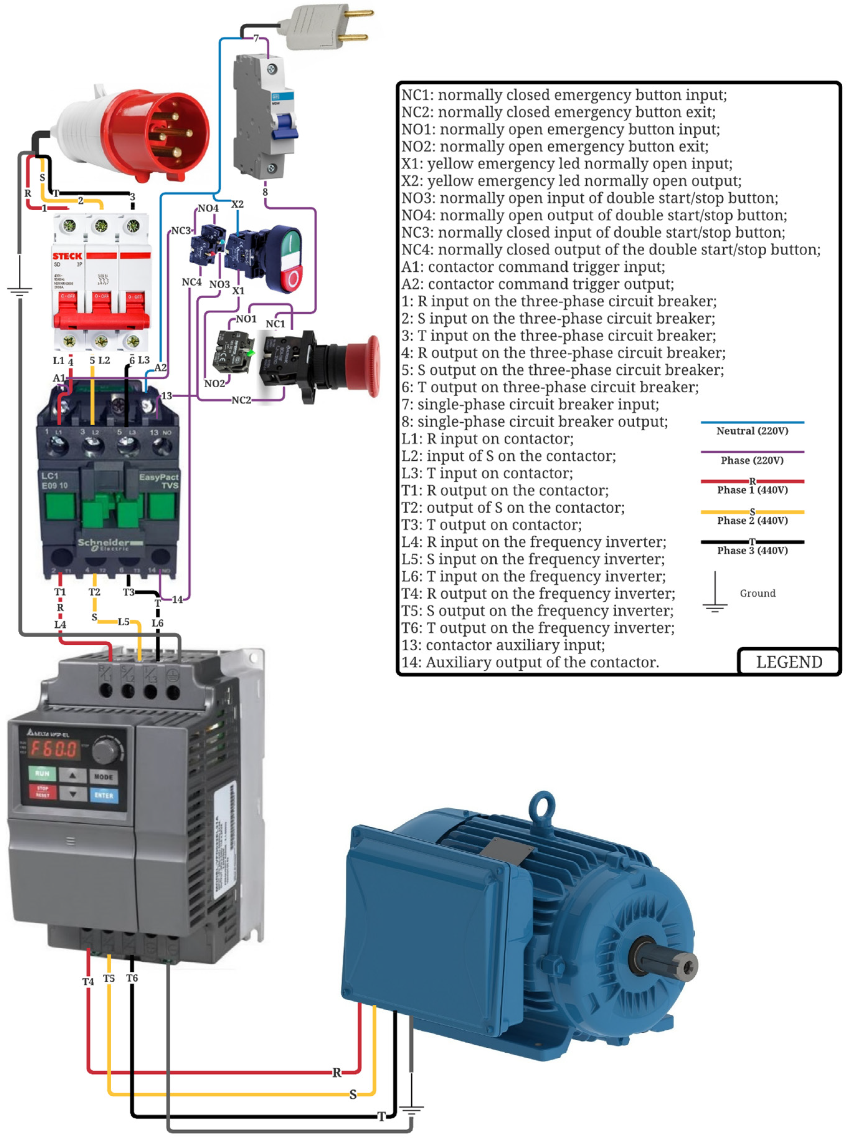
After the proposed tribometer’s manufacturing and assembly were completed, the setup was carried out with two different lubricants: (a) commercial mineral oil and (b) epoxidized soybean oil. Their properties are described in Table 1. Soybean oil is visibly more viscous than mineral oil, and it is worth noting that it is also an oil that does not contain additives. The tests analyzed different load stages and wear resistance of gear teeth. Also, vibration signals were monitored with the acquisition rate of 5 kHz, and lubricant temperature was measured. All gears were made of SAE 1045 steel, which is 7 mm thick; the primitive diameter (DP) of the crown was 40 mm, while that of the pinion was 28 mm. The gears have the features presented in Table 2, where z, m, dp, ϕ, t, β, and E are the number of teeth, the module, the pitch diameter, the pressure angle, the width of gear teeth, the helix angle, and the material modulus of elasticity, respectively. Three tests were performed, each with six load stages lasting two hours each, starting from 9.8 to 14.8 N, adding 1 N at each stage. Each test was twelve hours; after each, the gear teeth were analyzed with optical microscopy to evaluate the tooth wear. The vibration and temperature signals were collected for 30 s at 30 min and 105 min for each stage. Both oils were analyzed simultaneously; gearbox one was lubricated with commercial mineral oil and gearbox 2 with soybean oil; in each gearbox was added 80 mL of lubricating oil. The amount of oil placed in each box was up to one-third of the external diameter of the crown so that the crown lubricated the pinion. To analyze the sensibility of vibration signals and lubrication action, SAE 1045 steel filling was added to the lubricant to simulate oil contamination of gear wear (debris) in a concentration of 0.1% wt. The size distribution of filling is shown in Figure 1; 65% of filling has a size between 75 and 109 µm.

Table 1.
Physical and chemical properties of lubricant oils.
Table 2.
Selected gear features.
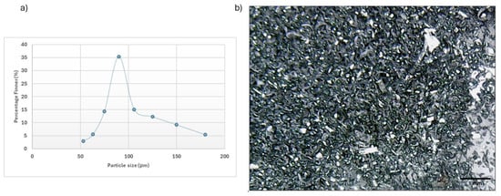
Figure 1.
Particle size distribution of filling (a) and micrograph of filling (b).
3. Results and Discussion
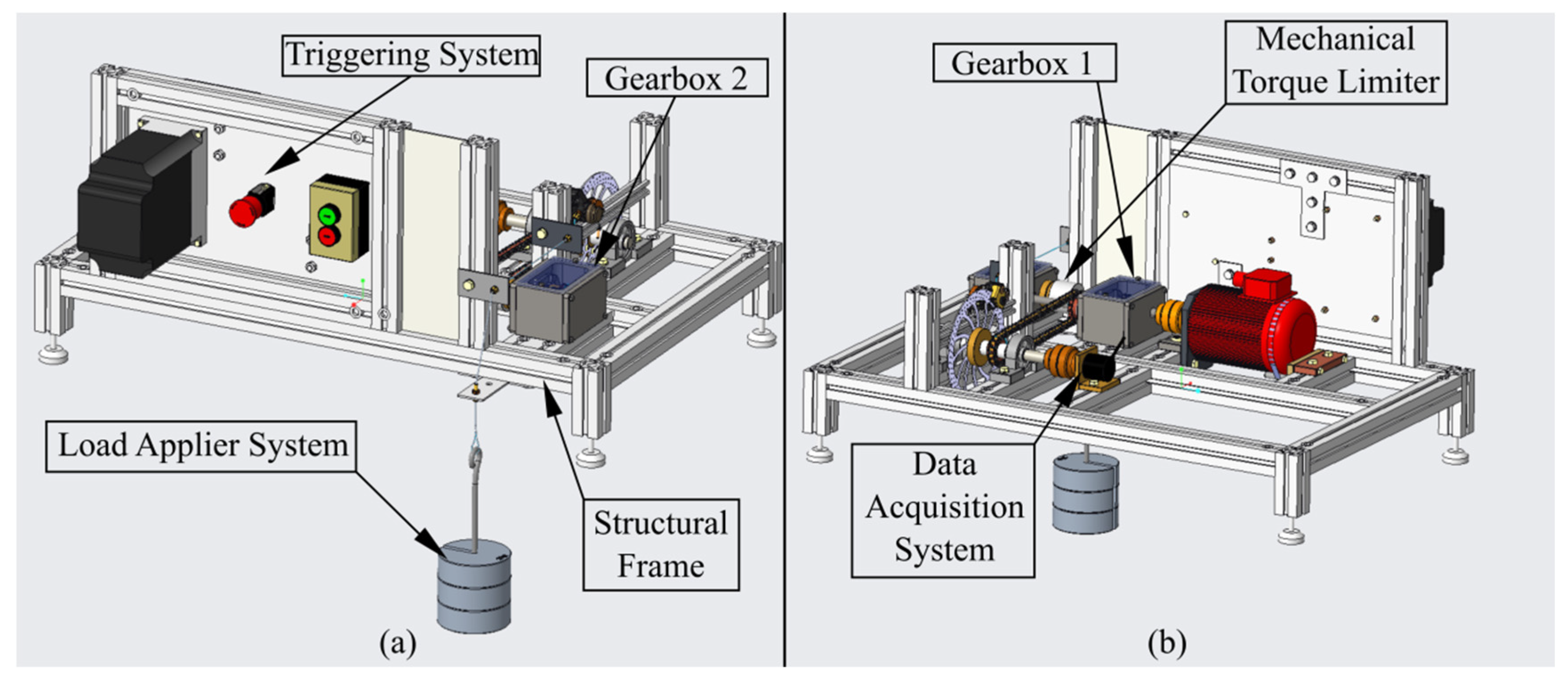
Figure 2 presents the innovative conceptual design of the mechanical system for the tribological test rig according to ISO 14635-1 [7] and the requirements defined for the current proposal.
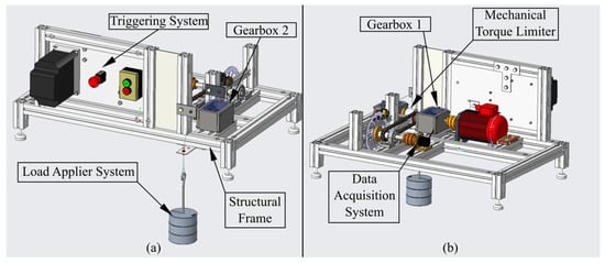
Figure 2.
Conceptual design of the mechanical system for the tribological test rig: (a) front side perspective view and (b) back side perspective.
According to Figure 2, six subassemblies are identified: (a) the gearboxes; (b) the load applier system; (c) the triggering system; (d) the structural frame; (e) the mechanical torque limiter; and (f) the instrumentation and data acquisition system. An approach to allow an understanding of the mechanical system is to follow the power flow, which initiates the triggering system. This system triggers the electric motor, which is coupled to the shafts of the gearboxes. The shafts transmit power between the gearboxes in a power-recirculating system. The gears’ tooth surface load is imposed when the load system is coupled to one of the gearboxes’ shafts by sprocket gears and chain. This loading system is composed of the third shaft, a disc brake, a caliper, a steel cable, and associated standardized masses aiming to create a known torque for the gearboxes’ shaft (i.e., pressing the caliper on the disc brake surfaces imposes a load in the system). Since the power-recirculating system between the two back-to-back gearboxes is closed, the upcoming considerations must be on the load application. Hitherto, the torques presented in the test rig came from the motor power and load applier system association.
Furthermore, the maximum internal torque is restricted by the mechanical torque limiter. Thus, the torque of the test rig can be increased to the required load values without the need to turn off the driving motor. This point is emphasized as the main improvement of the proposed conceptual design compared with the other system designs described in the literature and based on mechanical load systems. The continuous load change in gear pairs is the reality in most mechanical systems, and the current system proposal explores this condition.
The tribometer was designed with an electrical control system to carry out safe starts and stops. For this, a control system was designed using a 220 V Schneider LC1E09 contactor, Rueil-Malmaison, France, which is activated by a start/stop button. A circuit breaker and an emergency stop button protect the control system. The actuation of the emergency button disables the contactor and interrupts contact between the three-phase network and the motor. The motor powered by the three-phase network is controlled by the WEG CFW 09 frequency inverter, which is also protected by a circuit breaker. A schematic diagram is presented in Appendix A.
Lastly, the whole test rig was designed to be supported by a structural frame that is also versatile to add, relocate, and remove subassembly components or transducers. Therefore, the test rig was designed to be borne by an aluminum alloy structural frame that can be assembled easily with adaptable junctions. Although the material’s damping effect can be estimated by comparing the materials’ loss factors, and the aluminum’s loss factor is lower than the steel’s or iron’s loss factor, the difference is minimal compared with the gain provided by other properties [28] For instance, comparing the density, iron and steel can be almost three times denser than aluminum alloys [29,30]. The conceptual design also uses rubber isolation feet to minimize the undesired vibration propagation along the system. Moreover, this difference minimally influences the aluminum bending stiffness because of strengthened cross-section geometry.
Thus, with this subassembly overview, it is possible to visualize the working principle of this mechanical transmission test rig. The details of the subassemblies will be presented in upcoming sections. As can be seen in Figure 2, the conceptual design also meets three general objectives: (a) it can be operated by a single operator, as all locations for commands are on one side of the system; (b) it has an area of 0.5 m2; and (c) it allows simultaneous tests to be carried out with the same conditions in each gearbox, since the load applier system is external and is connected to a shaft shared by the two gearboxes. Once the proposed conceptual design has been presented, it is worth detailing each subassembly working principle.
3.1. The Gearboxes and Shaft System
The detailing of the subassemblies begins with the gearboxes’ subassembly, according to Figure 3. A discussion about the gears’ wear formation, their lubrication, and other factors that may influence the tribological phenomena can be realized based on its working principle.
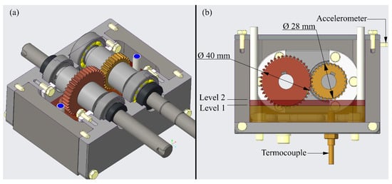
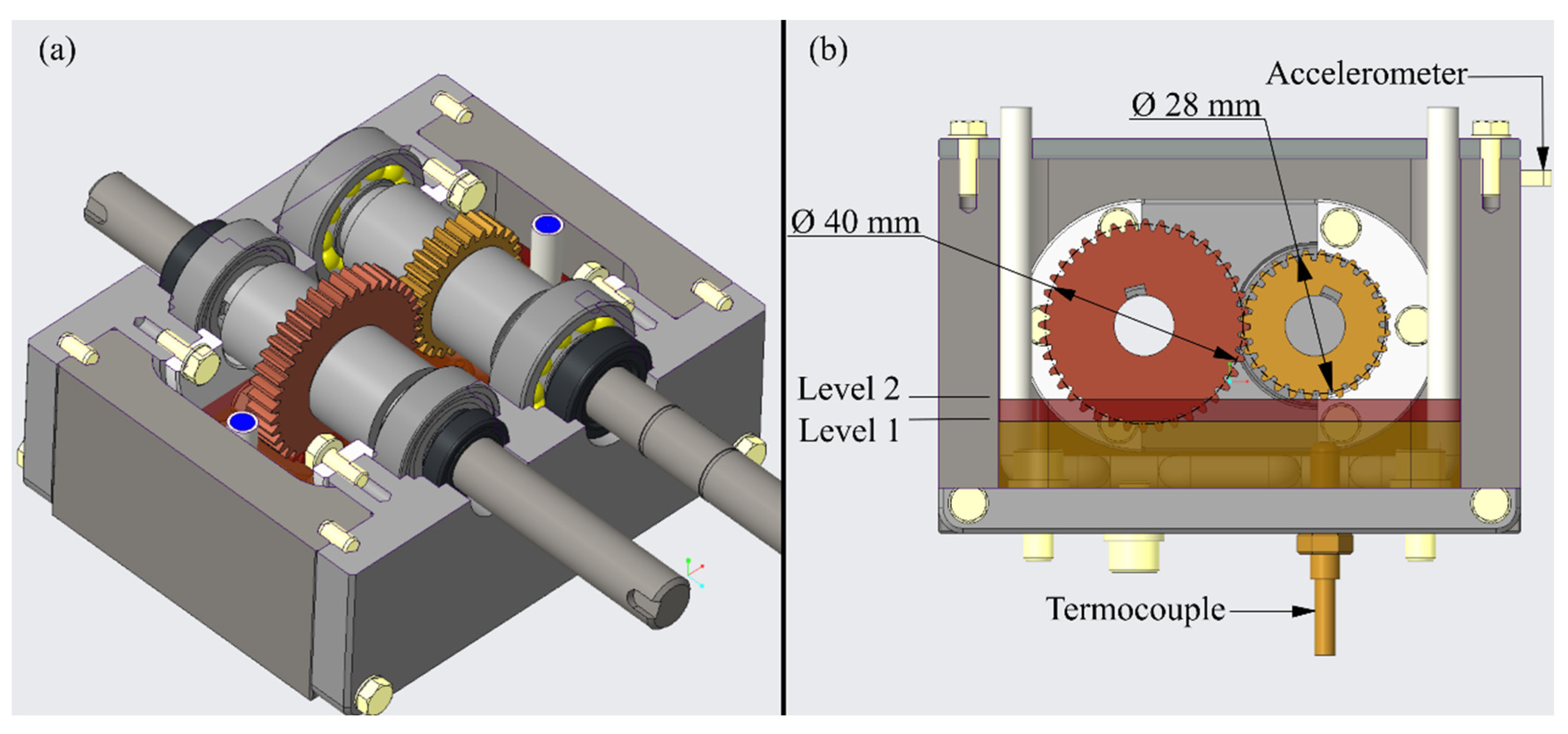
Figure 3.
Detail of the proposed gearboxes’ conceptual design: (a) a sectioned perspective and (b) a sectioned front view.
As shown in Figure 3a, the gearboxes’ structures are split into three main mechanical components: a case and two bearing house covers. The case is a hollow prismatic form with rectangular round entries to hold the bearing house covers. The bearing house covers are the parts in charge of closing the case, forming a reservoir for the lubricating oil, and bearing the shafts with the aid of the rolling bearings and radial shaft seals.
Inside the gearboxes, some parts are assembled on the shafts and at the gearboxes’ bottoms. In the shafts’ middle section, the main part of the gearboxes is the transmission. The mechanical transmission is realized by two spur gears whose pitch diameters are 28 and 40 mm for the pinion and the gear, respectively. This proposed pitch diameter gives a meshing ratio of 1:1.429, which draws near the ratio of the standardized test rig, and a center distance between shafts . Furthermore, considering that the oil level depends on the gears module, as explained in the previous section, the smallest module size was chosen in Series I of ISO 54 [24]. Thus, the chosen gears’ module was 1 mm. The proposed mechanical transmission has a gear thickness of 7 mm, which directly influences the Hertzian stress contact. However, according to the test’s goals, the mechanical design allows the gears’ thickness to be increased up to 28 mm. These modifications can be achieved by changing the thickness of the spacer bushes. They play an important role in maintaining the gears in their correct positions and can be easily changed according to the test’s needs.
Since the gears’ dimensions were defined, it was possible to size the subsequent elements: the shafts and the rolling bearings. To dimension the shafts, it is necessary to consider Equation (8), which calculates the torque present in the gears () as a function of the Hertzian stress contact () induced by the loads on the gears’ teeth. The other variables of Equation (8) depend on the determined gear dimensions. In this case, the dimensions of the pinion (identified by sub-index 1) were considered, which develops higher torque values (). Thus, the considered values for Equation (8) are described as follows: and . Thus, considering the presented values, Equation (8) presents the following relation between the pinion’s torque and the Hertzian stress contact at the pinion’s teeth:
Equation (11) describes the direct relation between the pinions’ torque and the Hertzian stress contact and, as in ISO 14635-1 [7], presents a range of Hertzian stress contacts to be achieved for the scuffing test. Furthermore, as this design represents a novel and downsized tribometer, the first two load stages were considered for the dimension of the shaft, which follows Mott’s approach to the shaft’s design [31]. As a result, the shafts were manufactured of AISI 1045 quenched and tempered steel to 500 HB with a diameter of 12 mm.
The design process involved assessing the shafts and loads on the driven shaft to determine suitable bearings using Equation (10). Assumptions were made, including the inner race rotating while the outer race remains stationary, resulting in the design load equaling the force applied on bearings , reaching 264.67 N. With purely radial loads, single-row ball bearings () were chosen, aiming for a bearing life of 1500 h at 1450 rpm. A safety margin for maximum torque operation was achieved with a design factor N = 2. The resulting basic load rating was , leading to the recommendation of a 6201 ball bearing. However, due to the center distance between the shafts (), the 6001 ball bearing was chosen for the driving shafts, each supported at two points. The gearboxes incorporated essential elements: a K-type thermocouple for oil temperature monitoring, a cooler system for temperature stabilization based on thermocouple data, and a drain for post-test gearbox cleaning. These elements collectively ensured the robust design and functionality of the gearboxes.
3.2. The Load Application System and the Mechanical Torque Limiter
A loading system based on a disc brake and brake caliper driven by standardized counterweights was developed to maintain a wear rate on the gear teeth compatible with the proposed test. The loading system consists of a caliper and brake disc mounted on a shaft parallel to the tribometer shafts. The brake caliper, triggered by a steel cable with standard masses at its end, applies braking force to the disc. The torque generated by braking from the brake disc is transmitted to the shaft by a flange, and the loading shaft transmits the braking torque to the tribometer-driven shaft by chains and sprockets (as can be seen in Figure 4). Unlike the ISO 14635-1 [7] tribometer, which features a loading system coupled directly to the driven shaft, this work proposed a loading system designed on a third shaft external to the gear train shaft. Therefore, using a couple of gearboxes to carry out simultaneous tests under similar conditions is possible.
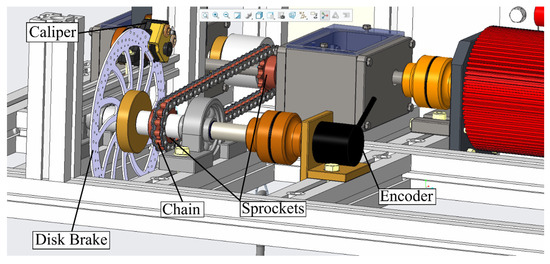
Figure 4.
Load system of the reduced FZG tribometer.
Considering the solution proposed, the assurance that the two pairs of gears are perfectly meshed using two continuous shafts configuring a power recirculation system is a challenging task, as minimal inaccuracy in the manufacturing and/or assembly of the components involved may cause angular misalignment between the shafts and compromise the meshing of the two pairs of gears. Therefore, to allow the meshing between the two pairs of gears involved in the power recirculation system, it was established that the drive shaft must be split into two shafts coupled by a mechanical torque limiter (according to Figure 5a).
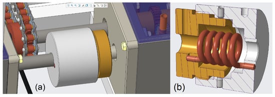
Figure 5.
Spring intermediate coupling of the reduced FZG tribometer.
In work conditions, the mechanical torque limiter must impose a value greater than that defined in the test. The external and internal coupling elements are assembled using an M42x2 thread to reveal overloads, if they occur, due to alignment marks on the outer diameters of each element. A point to be highlighted is to avoid the system locking in the thread; a sliding fit between the internal and external diameters of the coupling elements guides the connection. Therefore, threaded mounting allows the shafts to rotate around their axes without locking. Hexagon socket set screws with flat points allow the easy assembly of the second shaft. Moreover, according to Figure 5, a torsional spring must be assembled between these coupling elements. During the assembly, the internal coupling element must be twisted using a torque wrench while the external element remains blocked. The torque applied to twist the coupling must be (1) in the opposite direction to the torque applied by the motor; and (2) of a magnitude greater than the torque applied for the test. Thus, the torque applied to the coupling is stored in the torsion spring as elastic potential energy. The spring applies torque to the subsequent shaft to force the contact on the second pair of gears and eliminate possible backlash. In this way, once the electrical motor is started, the electrical motor torque does not overcome the spring torque, and the preload applied by the mechanical torque limiter is sufficient to maintain the gear despite any play or deviation that the system may present during assembly. This design approach meets the requirements (3a–c and 6a,b) for subassembly load applier systems and mechanical torque limiters.
The mechanical design approach described for the load application and torque limiter subassemblies is considered innovative compared with those presented in the literature [9,14]. It does not use the electromagnetic principle for loading applications, and simultaneously, it has a dynamic load system. On the other hand, the torque limiter system allows an equal distribution of torque in both gear pairs inside the gearboxes and a clear identification if overloads occur due to a change in the wear mechanism or a catastrophic failure.
3.3. Instrumentation and Data Acquisition System
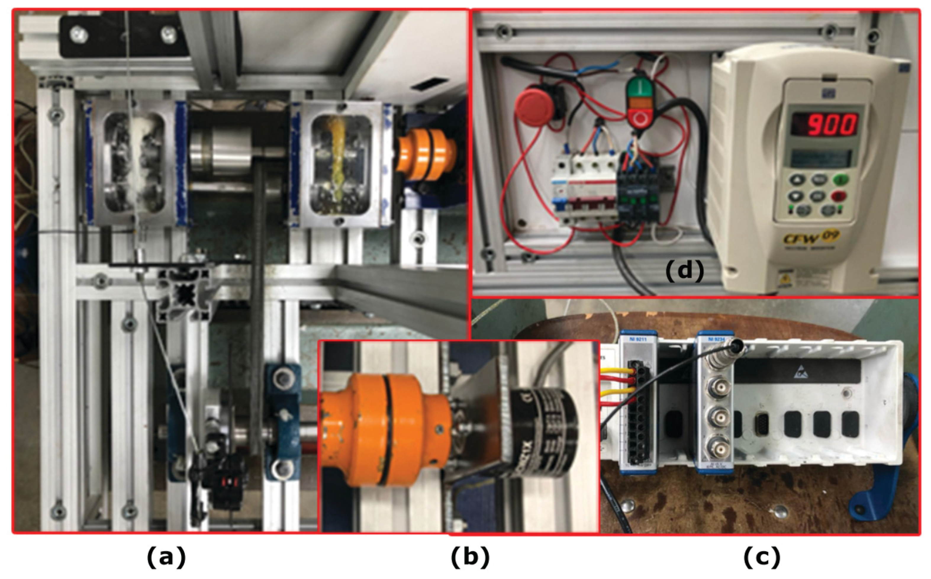
The proposed tribometer was designed to monitor shaft angular speed, oil sump temperature, and the gearboxes’ amplitude and frequency vibrations in real time. This planning aims to optimize the control process using actuators and integrate the monitoring system and the drive system. Figure 6 shows the tribometer components assembled on the lab bench.
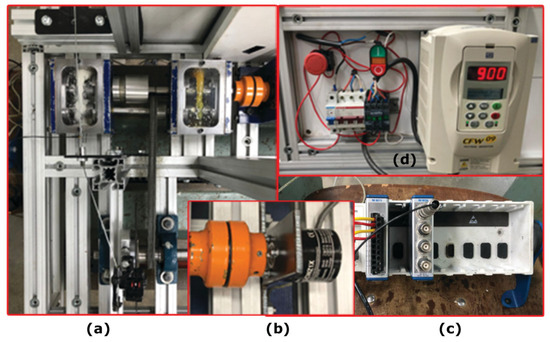
Figure 6.
Tribometer components assembled on the lab bench.
Figure 6a shows a top view of the system with the two gearboxes in operation, which are driven by the main shaft associated with the mechanical torque limiter device. It is possible to identify the third shaft in Figure 6b, which imposes torque on the system based on a caliper and a brake disc, as described earlier. The angular velocity monitoring is determined with an incremental encoder, model E6B2-CWZ1X, supplied by the Omron Automation and Safety Company and assembled at the end of the shaft, as shown in Figure 5b.
Figure 6c shows the data acquisition device based on the c-DAQ 9178 chassis integrated with the LabView® 2011 software. In this case, two specific modules have been used: NI-9211, which has four channels for lubricant temperature measurement, and NI-9234, which has four channels for measuring vibration from piezoelectric accelerometers. Thermocouples type K (range between −200 and 1260 °C), supplied by the ECIL Company, were installed inside a hole in each gearbox bottom surface (in contact with the lubricant). The acquisition rate for temperature data was 100 Hz, and the computational code calculated the average values obtained in each temporal window. The conceptual design identifies the increase in lubricant temperature during the test in cases of procedures initiated at room temperature or, with future adaptation, in situations using an oil heating system in each gearbox.
Regarding acceleration measurement, a uniaxial accelerometer model 4518, supplied by Brüel & Kjaer, was mounted on the gearbox housing side surface. The acquisition rate used was 5 kHz, and the computational code identified peaks and valleys in addition to amplitude and frequency in each temporal window. The concept of using the accelerometer is to identify, based on amplitude, frequency, or peaks and valleys data, changes in wear mechanisms or damage acting on the tribological system.
Figure 6d shows a front view of the triggering panel (without the protective cover) to allow an understanding of the connections, and it is possible to identify the frequency inverter, model CFW 09, developed by the Weg Company. This equipment allows adjusting the angular velocity of the drive motor to comply with the 12 loading stages described in ISO 14635-1 [7]. The same image also identifies the start/stop and emergency buttons and the system’s protective circuit breakers.
Finally, the computational codes developed in LabView® allow the operator to visualize, in real time, the angular velocity of the shafts; the temperature variation in each gearbox; and the amplitude, frequency, and identification of peaks or valleys in the acceleration signal. Based on the information, the operator can monitor the number of cycles of each loading stage, as described in ISO 14635-1 [7]. As mentioned earlier, the fundamental monitoring point with the data is the correlation between changes in wear mechanisms or damage on the gears’ teeth and the monitored signals. Once it is understood that a particular mechanism promotes a specific signal, the procedure can be extrapolated to real applications to interrupt a system’s functioning before costly damage occurs.
3.4. Experimental Test
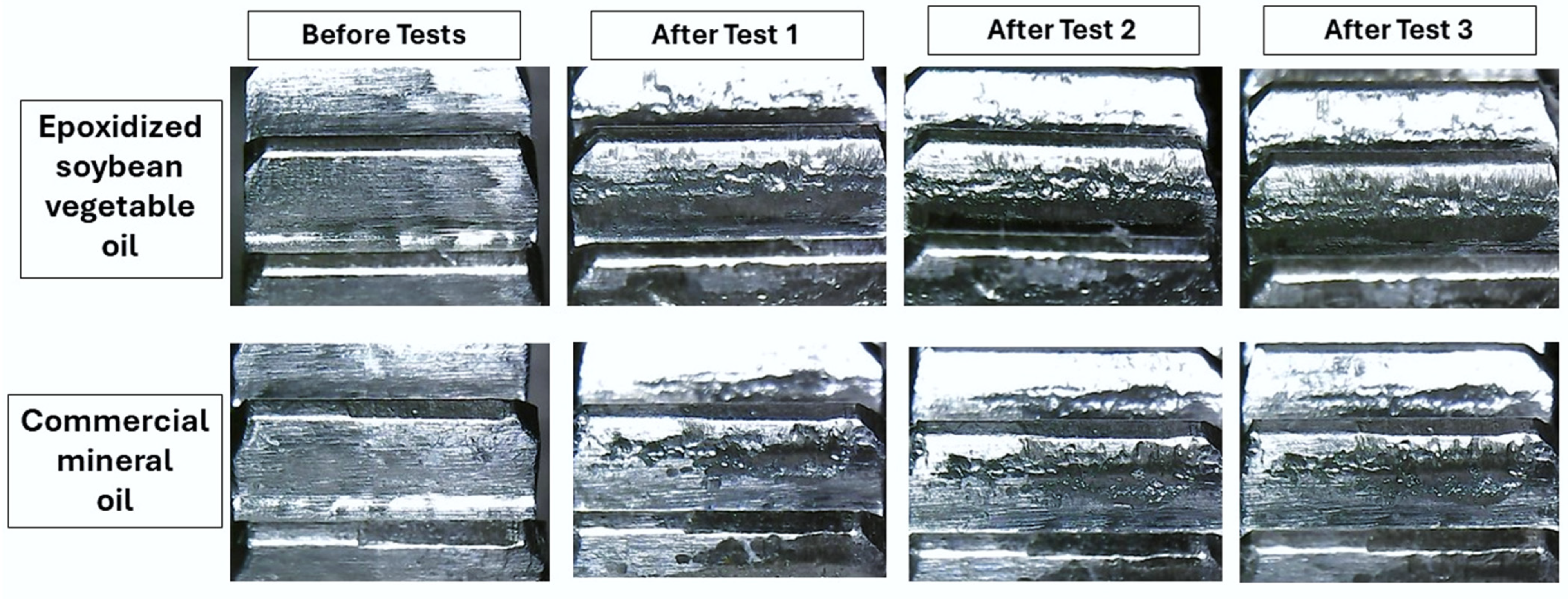
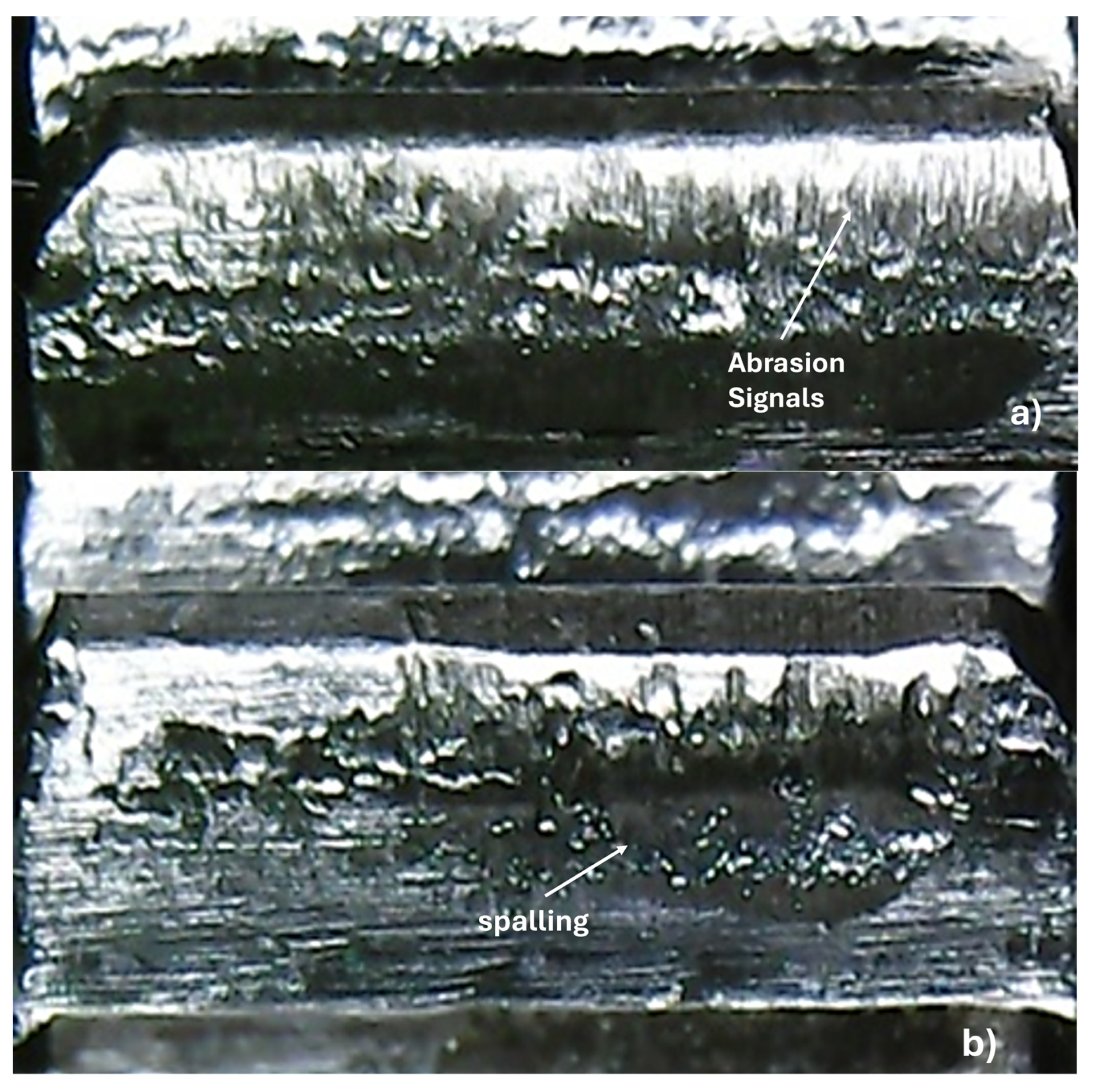
The designed setup was used to understand the lubricating ability of different oils. Therefore, it allowed the evaluation of two lubricants simultaneously with different load stages, monitoring signals of vibration and temperature. The first intention is associating the vibration signal with gear wear mechanisms or phenomena. Figure 7 shows the tooth wear before and after tests. In this case, test 1 analyzed the ability of lubricants to minimize the wear rate; as can be seen in the second column, it is possible to observe that there are differences in the wear mechanism. Vegetable oil reduced the extension of tooth damage; some micropitting can be seen near the gear’s primitive diameter. On the other hand, when gears were lubricated with mineral oil, scuffing and micropitting were the main wear mechanisms; however, they produced a more damaged tooth surface. This outcome can be attributed to the higher viscosity of vegetable oil and its ability to adhere to worn surfaces [32]. The addition of steel fillings led to different behavior depending on the type of base oil used, which was linked to the greater viscosity of the vegetable-based oil. The filling dispersed and acted as a third body in the contact area, resulting in spalling and signs of abrasion, thereby altering the wear mechanism. In contrast, the wear observed during the mineral oil tests followed the same mechanism (scuffing and micropitting), with the fillings merely increasing the scuffing signals (abrasion). Figure 8 shows more details of the worn surface after test 3 for both oils.
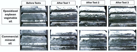
Figure 7.
Wear in gear tooth before and after tests.

Figure 8.
Worn gear tooth after test 3 for vegetable oil (a) and mineral oil (b).
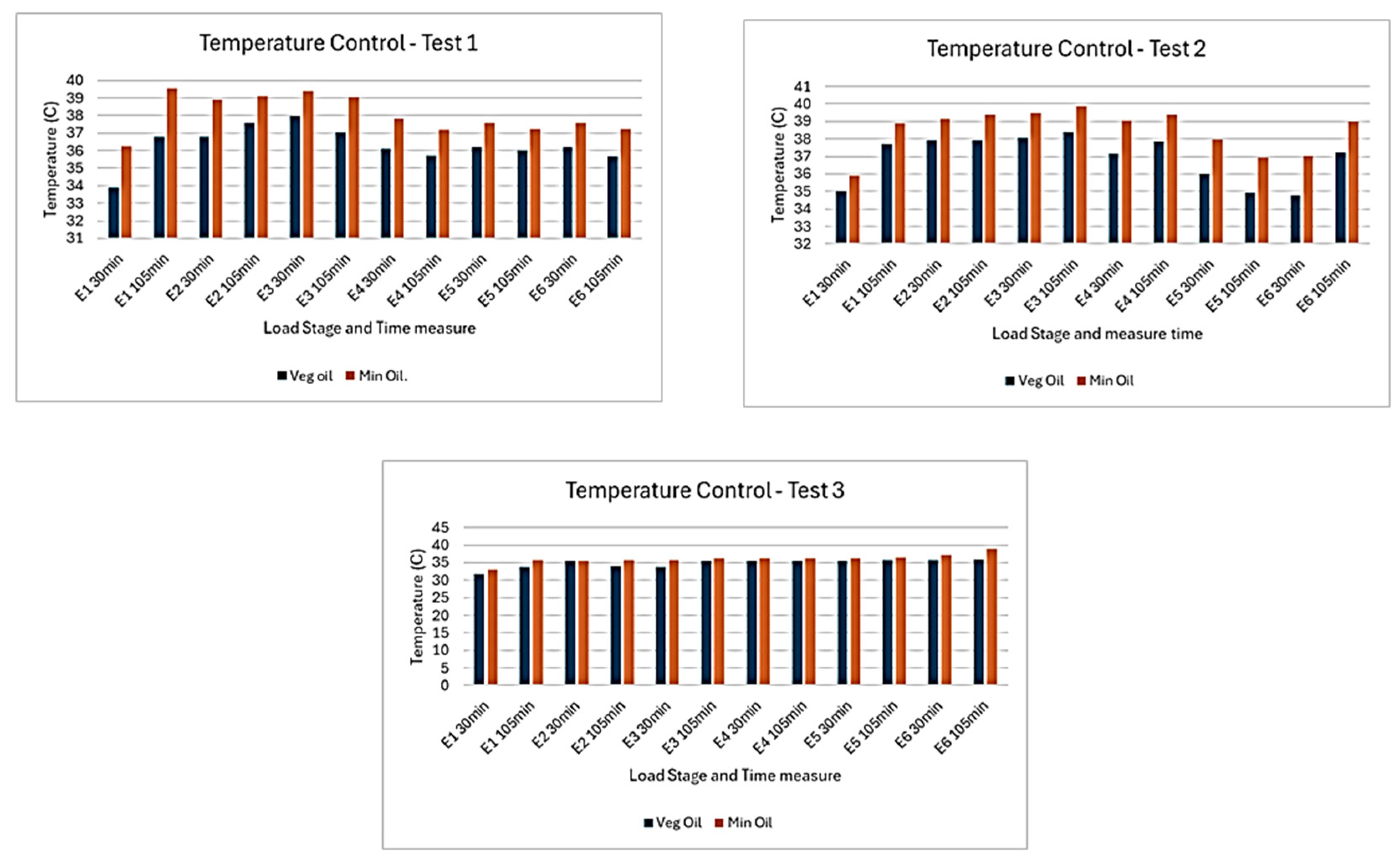
Regarding temperature monitoring in the tribological test (Figure 9), some considerations can be made: (i) Even 12 h of contact was not enough to increase lubricant temperature significantly, and only an increment of 3 degrees Celsius was achieved on average temperature; also, after the third stage, the temperature was kept at the same level until test end. (ii) The mineral oil temperature was higher than that of the vegetable oil, which was related to the better lubrication performance of vegetable oil, which is more viscous, reducing friction and heat generation. (iii) The addition of steel filling minimized temperature effects, aided heat dissipation, and increased the amount of filling, which became the lubrication behavior similar to both oils.

Figure 9.
Temperature monitoring during tribological tests.
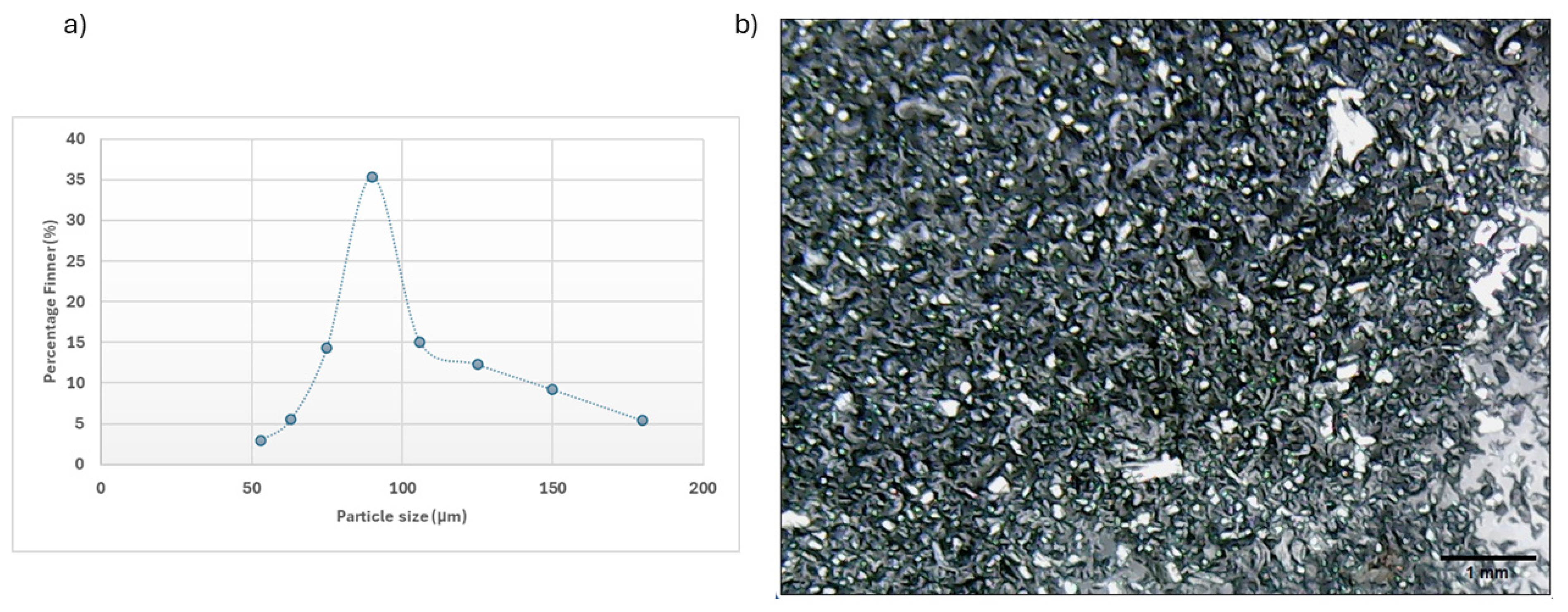
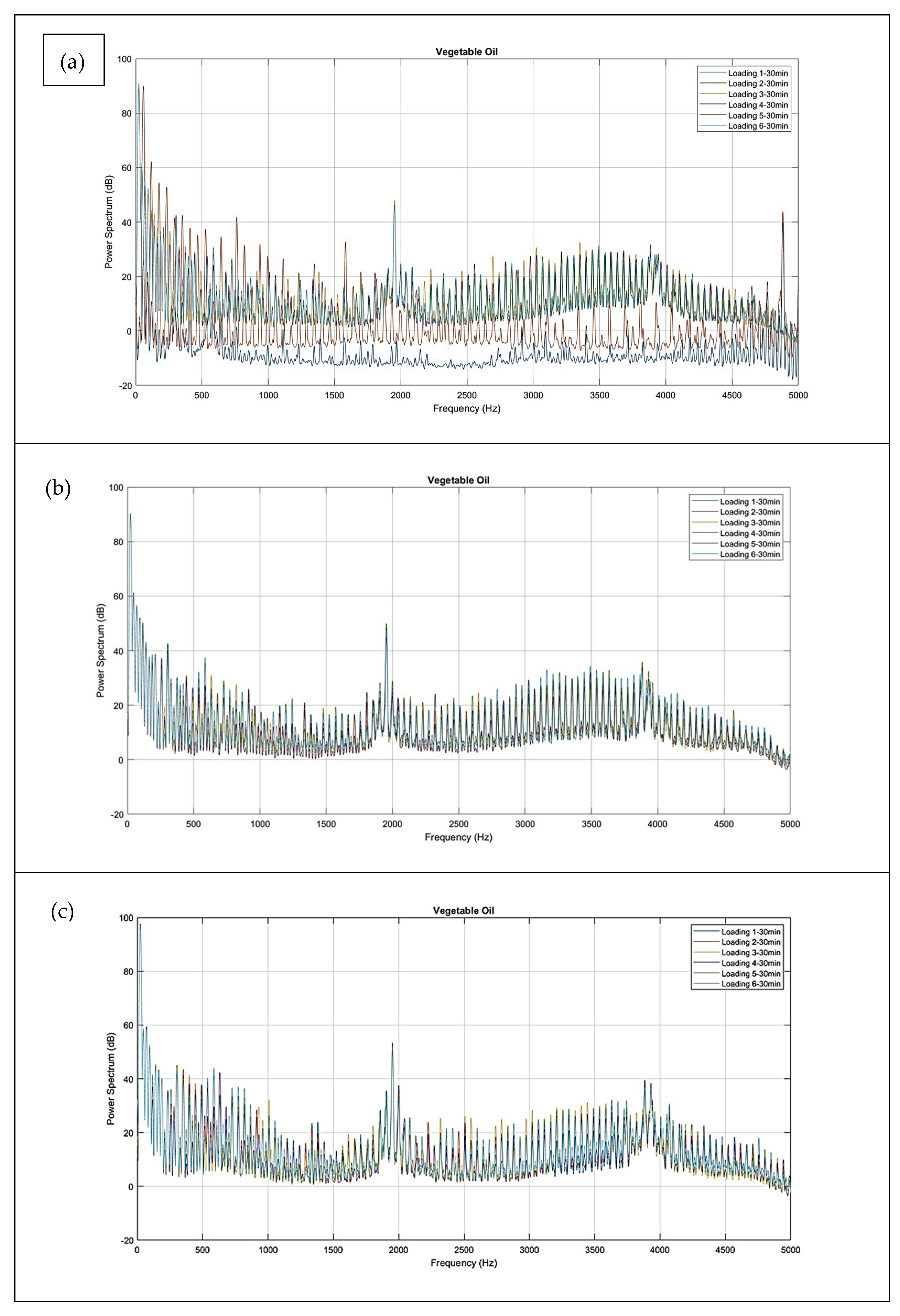
Vibration measurement is a technique that can detect damage in mechanical components, and the Fast Fourier Transformation (FFT) is one of the most common methods to analyze vibration signals. This tribometer was instrumented with accelerometers as described previously. Figure 10 and Figure 11 show the frequency spectrum obtained by FFT from the vibration signals collected in the tribological tests considering the loading stage at each test. The lubrication effect on gear wear from the tests lubricated with vegetable oil can be analyzed in Figure 10. At the beginning of the test, with base oil only in the first stage, it was not possible to identify a variation in vibration signals, indicating that frequencies from the rotation of the shaft and plain bearings, as well the electrical network, were not perceived after signal analysis. With the increase in loading and contact time, there was an increase in the intensity of the signal and formation of characteristic frequencies around 1.9 and 3.9 kHz. These frequencies were associated with gear wear after the running-in period (first two stages), as verified in the images of Figure 7 after test 1 of scuffing and micropitting wear on the tooth surface. According to Medeiros et al. [33], micropitting may lead to noise, vibrations, and misalignments. After the third stage, the frequency intensity increased slightly with additional loading. Also, as mentioned above, adding steel fillings (tests 2 and 3) did not promote a considerable increase in gear damage, agreeing with the vibration spectra where the initial frequencies were kept.
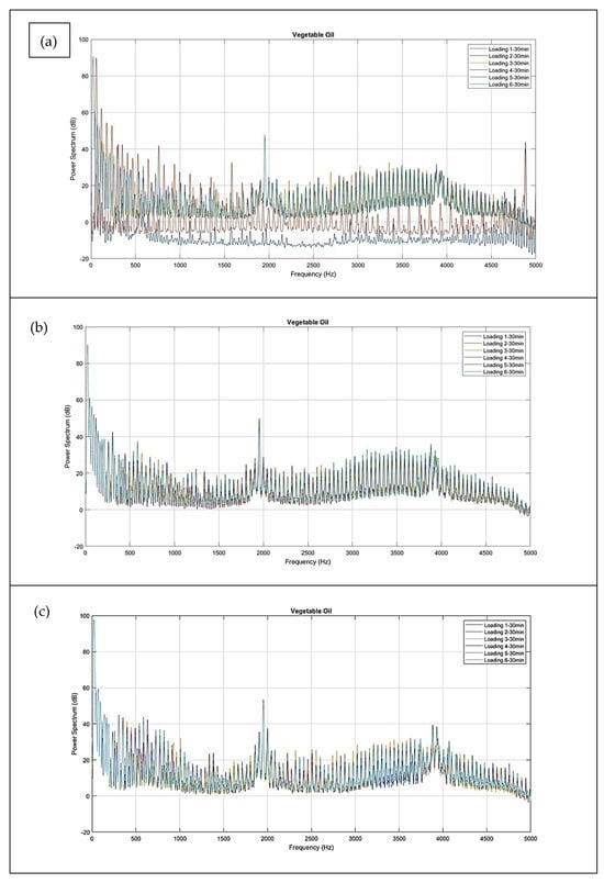
Figure 10.
Frequency spectra by FFT for tribological test with vegetable oil: (a) test 1, (b) test 2, and (c) test 3.
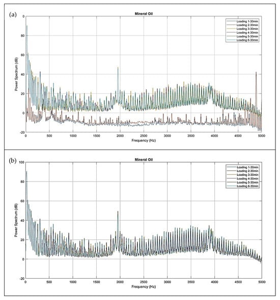
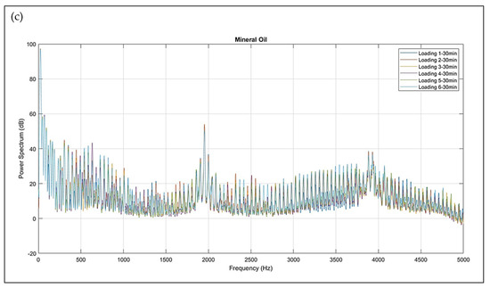
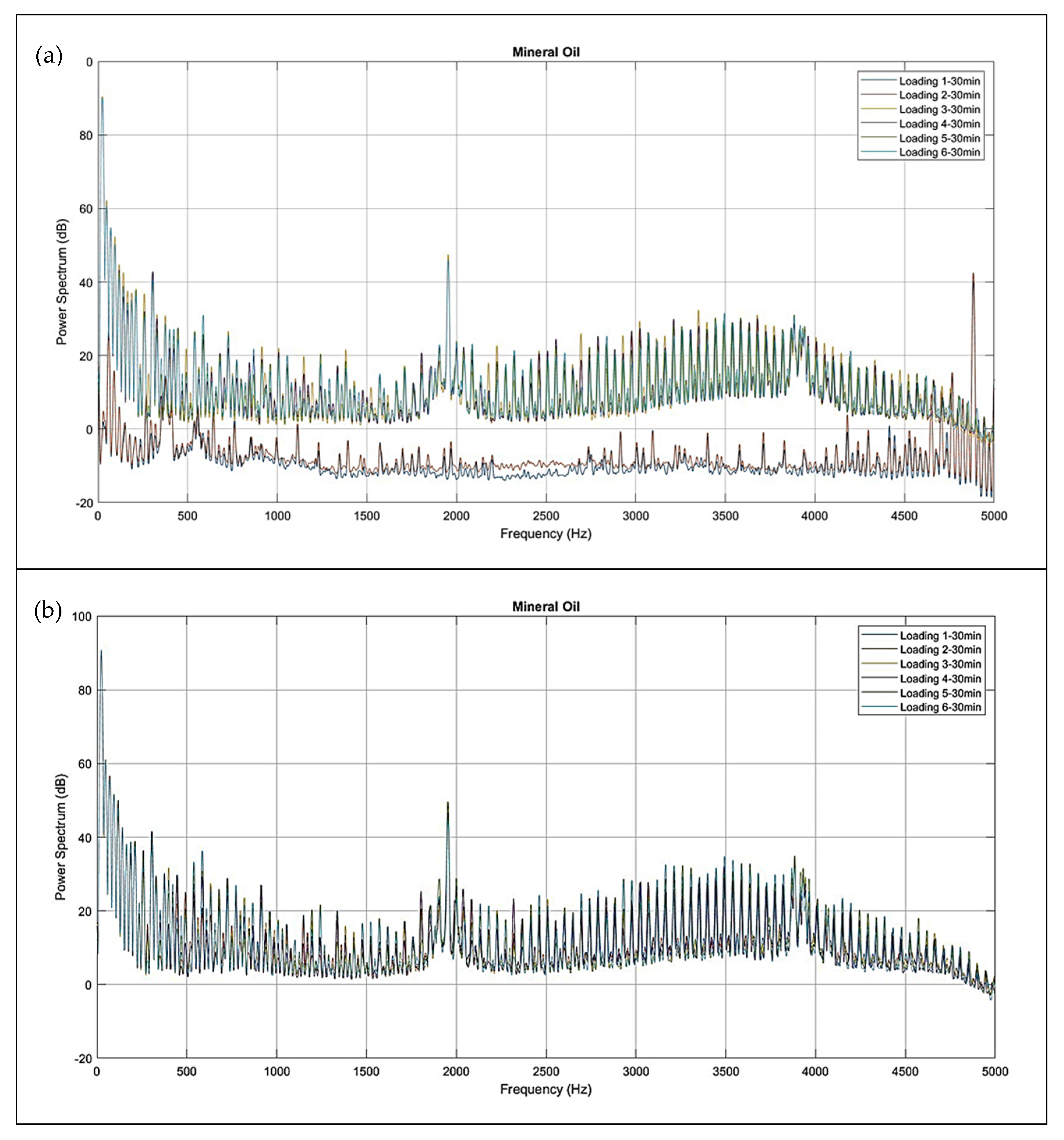
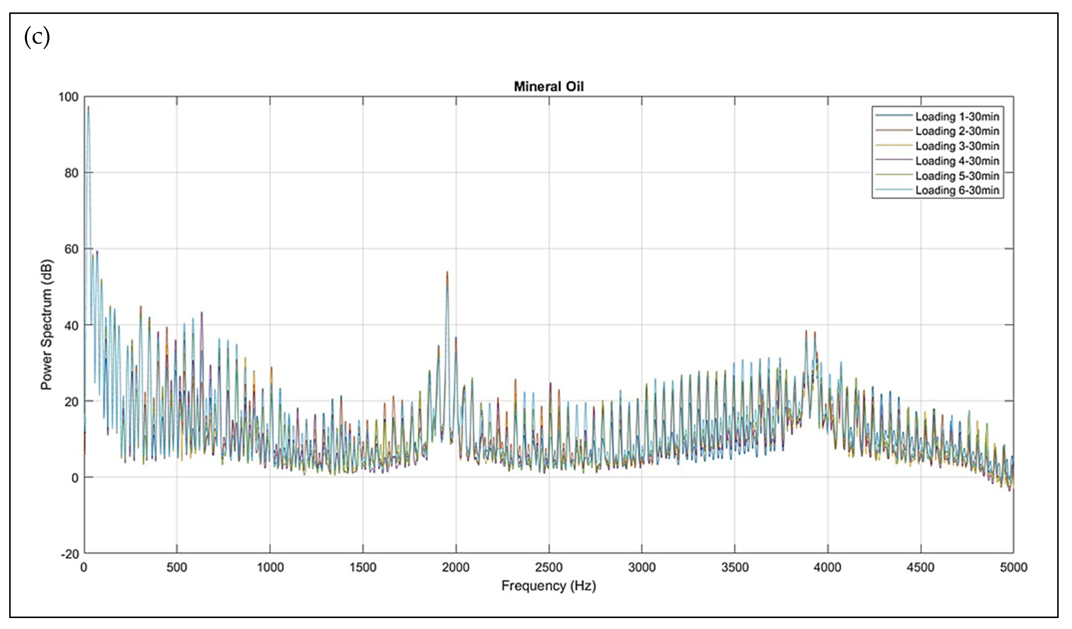
Figure 11.
Frequency spectra by FFT for tribological test with mineral oil (a) test 1, (b) test 2, and (c) test 3.
Figure 11 shows the vibration spectra for tests lubricated with fully formulated mineral oil. Analyzing test 1, just with lubricating and without contamination, there were observed differences in the two first stages; even with the load increase in the second stage, the vibration spectra are practically the same, indicating that the wear on the gear surface was more abrupt that with than vegetable oil. This finding suggested that a lack of proper lubrication increased tooth contact and friction. The addition of the filling leads to a slight increase in wear but does not produce significant changes in the vibration signal, as shown by the frequency spectrum in tests 2 and 3. The signal intensity remains consistent with the final step of test 1. These results are similar to those observed with vegetable oil, indicating that both the amount and size of the filling are minimal and do not interfere with the gearing.
4. Conclusions
This article has described the mechanical design of an innovative ribometer for testing spur and helical gears under closed lubrication conditions following ISO 14635-1 [7] but with the advantages of allowing small quantities of lubricants (50 to 100 mL), which is an economic gain for testing oils with nano additives or ionic liquids and the dynamic change in loads among the twelve stages foreseen in the procedure. Based on the results obtained, it can be concluded that
(a) The power recirculation system was modified to use a third shaft with loading transmitted by sprocket gears and chain to the tested gears. Variable loading is obtained with the support of a caliper and brake disc associated with a standard masses device system by steel cable.
(b) Although the design uses a purely mechanical system, the load application system allows dynamic load changes without interrupting the test. This point reflects the real behavior of mechanical components in working conditions and provides results closer to reality.
(c) The torque limiter system allows an identical distribution of loads in both gear pairs tested and, if overloads occur, an identification method based on markings on the outer diameter of coupling elements associated with a torsion spring.
(d) The gearboxes have essential monitoring transducers as encoders to evaluate the shaft angular speed, a K-type thermocouple to determine the oil temperature inside the gearboxes, and a uniaxial accelerometer aiming to measure amplitude and frequency vibrations in the gearbox case. All described transducers were connected to a LabView®-based real-time data acquisition and processing system.
(e) The pilot lubrication test was conducted with two different base oils, without and with contamination. The setup allowed evaluation of the lubrication ability in various loading conditions. The results showed that vegetable oil promoted better lubrication, decreasing damage to the teeth surfaces and heating of the lubricant. Monitoring vibration signals allowed for identifying the appearance of damage on the gear surface.
Author Contributions
Conceptualization, S.M.A., A.J.d.O., L.M.d.C.S.; Methodology, S.M.A., A.J.d.O., L.M.d.C.S.; investigation, L.M.d.C.S., A.M.A.R., J.J.d.O.J.; writing—original draft preparation: L.M.d.C.S., S.M.A., A.J.d.O.; writing—review and editing, S.M.A.; supervision S.M.A., A.J.d.O. All authors have read and agreed to the published version of the manuscript.
Funding
The article processing fee for publication of this research was funded by Coordenação de Aperfeiçoamento de Pessoal de Nível Superior—Brasil (CAPES) (ROR identifier: 00x0m\614), This study was financed in part by the CNPq (National Council for Scientific and Technological) and the Coordenação de Aperfeiçoamento de Pessoal de Nível Superior—Brasil (CAPES)—Finance Code 001.
Data Availability Statement
The original data presented in the study are openly available in https://repositorio.ufrn.br/items/0e02d21c-3f33-46db-b081-42b7bf83ebe1 (accessed on 15 February 2025).
Conflicts of Interest
The authors declare no conflict of interest.
Appendix A

Figure A1.
The triggering system of the reduced FZG tribometer.
Figure A1.
The triggering system of the reduced FZG tribometer.
References
- Budynas, R.G.; Nisbett, J.K. Gears-General. In Shigley’s Mechanical Engineering Design; McGraw-Hill: New York, NY, USA, 2011; Chapter 13; pp. 673–732. [Google Scholar]
- Hutchings, I.; Shipway, P. Tribology: Friction and Wear of Engineering Materials, Surface Topography and Surfaces in Contact; Butterworth-Heinemann: Oxford, UK, 2017; Chapter 2; pp. 7–35. [Google Scholar]
- Williams, J.A.; Dwyer-Joyce, R.S. Contact Between Solid Surfaces. In Modern Tribology Handbook Vol. 1; CRC Press: Boca Raton, FL, USA, 2001; Chapter 3; pp. 121–162. [Google Scholar]
- Axén, N.; Hogmark, S.; Jacobson, S. Friction and Wear Measurement Techniques. In Modern Tribology Handbook Vol. 1; CRC Press: Boca Raton, FL, USA, 2001; Chapter 13; pp. 493–510. [Google Scholar]
- Cheng, H.S. Gears. In Modern Tribology Handbook Vol. 2; CRC Press: Boca Raton, FL, USA, 2001; Chapter 29; pp. 1095–1129. [Google Scholar]
- Singh, H.; Singh, A.K.; Singla, Y.K.; Chattopadhyay, K. Design & development of a low cost tribometer for nano particulate lubricants. Mater. Today Proc. 2020, 28, 1487–1491. [Google Scholar] [CrossRef]
- ISO 14635-1; Gears-FZG Test Procedures-Part 1: FZG Test Method A/8,3/90 for Relative Scuffing Load-Carrying Capacity of Oils. International Organization for Standardization: Geneva, Switzerland, 2000; p. 1.
- Sagraloff, N.; Winkler, K.J.; Tobie, T.; Stahl, K.; Folland, C.; Asam, T. Investigations on the Scuffing and Wear Characteristic Performance of an Oil Free Water-Based Lubricant for Gear Applications. Lubricants 2021, 9, 24. [Google Scholar] [CrossRef]
- Fernandes, C.M.C.G.; Blazquez, L.; Sanesteban, J.; Martins, R.C.; Seabra, J.H.O. Energy efficiency tests in a full scale wind turbine gearbox. Tribol. Int. 2016, 101, 375–382. [Google Scholar] [CrossRef]
- Muraro, M.A.; Koda, F.; Reisdorfer, U., Jr.; da Silva, C.H. The Influence of Contact Stress Distribution and Specific Film Thickness on the Wear of Spur Gears During Pitting Tests. J. Braz. Soc. Mech. Sci. Eng. 2012, 34, 135–144. [Google Scholar] [CrossRef]
- Meneghetti, G.; Terrin, A.; Giacometti, S. A twin disc test rig for contact fatigue characterization of gear materials. Procedia Struct. Integr. 2016, 2, 3185–3193. [Google Scholar] [CrossRef]
- Meng, F.S.; Li, Z.; Ding, H.H.; Hu, J.S.; Wang, W.J.; Guo, J.; Liu, Q.Y. Study on the preparation and tribological properties of BN@C-OA nano-additive lubricants. Wear 2021, 474–475, 203876. [Google Scholar] [CrossRef]
- Han, X.; Zhang, Z.; Thrush, S.J.; Barber, G.C.; Qu, H. Ionic liquid stabilized nanoparticle additive in a steel-ceramic contact for extreme pressure application. Wear 2020, 452–453, 203264. [Google Scholar] [CrossRef]
- Yang, S.; Zhang, D.; Wong, J.S.S.; Cai, M. Interactions between ZDDP and an oil-soluble ionic liquid additive. Tribol. Int. 2021, 158, 106938. [Google Scholar] [CrossRef]
- Niza, M.E.; Komori, M.; Nomura, T.; Yamaji, I.; Nishiyama, N.; Ishida, M.; Shimizu, Y. Test rig for micro gear and experimental analysis on the meshing condition and failure characteristics of steel micro involute gear and metallic glass one. Mech. Mach. Theory 2010, 45, 1797–1812. [Google Scholar] [CrossRef]
- Van der Linden, F.L.J. Gear test rig for health monitoring and quasi static- and dynamic testing; design, construction and first results. In Proceedings of the International Gear Conference 2014, Lyon, France, 26–28 August 2014; pp. 976–985. [Google Scholar]
- Abruzzo, M.; Beghini, M.; Santus, C.; Manconi, S. Dynamic behavior of a power re-circulating gear test rig including periodic variation of mesh stiffness and static transmission error. Mech. Mach. Theory 2021, 159, 104247. [Google Scholar] [CrossRef]
- Li, K.; Modaresahmadi, S.; Williams, W.B.; Wright, J.D.; Som, D.; Bird, J.Z. Designing and Experimentally Testing a Magnetic Gearbox for a Wind Turbine Demonstrator. IEEE Trans. Ind. Appl. 2019, 55, 3522–3533. [Google Scholar] [CrossRef]
- Sen, P.C. Synchronous Machines. In Principles of Electric Machines and Power Electronics; Wiley: Hoboken, NJ, USA, 2013; Chapter 6; pp. 282–361. [Google Scholar]
- Almeida, G.M.J.; Pessoa, G.C.V.; Cardoso, R.A.; Castro, F.C.; Araújo, J.A. Investigation of crack initiation path in AA7050-T7451 under fretting conditions. Tribol. Int. 2020, 144, 106103. [Google Scholar] [CrossRef]
- Navet, P.; Changenet, C.; Ville, F.; Ghribi, D.; Cavoret, J. Thermal Modeling of the FZG Test Rig: Application to Starved Lubrication Conditions. Tribol. Trans. 2020, 63, 1135–1146. [Google Scholar] [CrossRef]
- Pirro, D.M.; Webster, M.; Daschner, E. Application of Lubricants. In Lubrication Fundamentals; CRC Press: Boca Raton, FL, USA, 2006; Chapter 9; p. 224. [Google Scholar]
- Provenza, F. Elementos de Máquinas. In Desenhista de Máquinas; Pro-Tec: São Paulo, Brazil, 1960; Chapter 6; pp. 1–106. [Google Scholar]
- ISO 54; Cylindrical Gears for General Engineering and for Heavy Engineering-Modules. International Organization for Standardization: Geneva, Switzerland, 1996.
- ISO 6336; Calculation of Load Capacity of Spur and Helical Gears. International Organization for Standardization: Geneva, Switzerland, 2006; pp. 1–6.
- Mott, R.L.; Vavrek, E.M.; Wang, J. Shaft Design. In Machine Elements and Mechanical Design; Pearson: London, UK, 2017; Chapter 12; pp. 509–545. [Google Scholar]
- Mott, R.L.; Vavrek, E.M.; Wang, J. Rolling Contact Bearings. In Machine Elements and Mechanical Design; Pearson: London, UK, 2017; Chapter 14; pp. 563–588. [Google Scholar]
- Rao, S.S. Vibration Control. In Mechanical Vibrations; Pearson: London, UK, 2010; Chapter 9; pp. 790–890. [Google Scholar]
- Cardarelli, F. Ferrous Metals and Their Alloys. In Materials Handbook: A Concise Desktop Reference; Springer: London, UK, 2008; Chapter 2; pp. 59–157. [Google Scholar]
- Cardarelli, F. Common Nonferrous Metals. In Materials Handbook: A Concise Desktop Reference; Springer: London, UK, 2008; Chapter 3; pp. 158–212. [Google Scholar]
- Norton, R.L. Spur Gears. In Machine Design-An Integrated Approach; NOVA: Hauppauge, NY, USA, 2010; Chapter 12; pp. 681–746. [Google Scholar]
- Alves, S.M.; Barros, B.S.; Trajano, M.F.; Ribeiro, K.S.B.; Moura, E. Tribological behavior of vegetable oil-based lubricants with nanoparticles of oxides in boundary lubrication conditions. Tribol. Int. 2013, 65, 28–36. [Google Scholar] [CrossRef]
- Medeiros, A.; Cardoso, R.R.; Júnior, J.J.O.; Alves, S.M. Failure analysis of gear using continuous wavelet transform applied in the context of wind turbines. Proc. Inst. Mech. Eng. Part J J. Eng. Tribol. 2024, 238, 860–868. [Google Scholar] [CrossRef]


Disclaimer/Publisher’s Note: The statements, opinions and data contained in all publications are solely those of the individual author(s) and contributor(s) and not of MDPI and/or the editor(s). MDPI and/or the editor(s) disclaim responsibility for any injury to people or property resulting from any ideas, methods, instructions or products referred to in the content. |
© 2025 by the authors. Licensee MDPI, Basel, Switzerland. This article is an open access article distributed under the terms and conditions of the Creative Commons Attribution (CC BY) license (https://creativecommons.org/licenses/by/4.0/).