Ti-C and CFs Work Together to Enhance the Comprehensive Tribological Properties of PTFE-Based Composites for the Manufacture of Wave Glider Power Shafts

Abstract
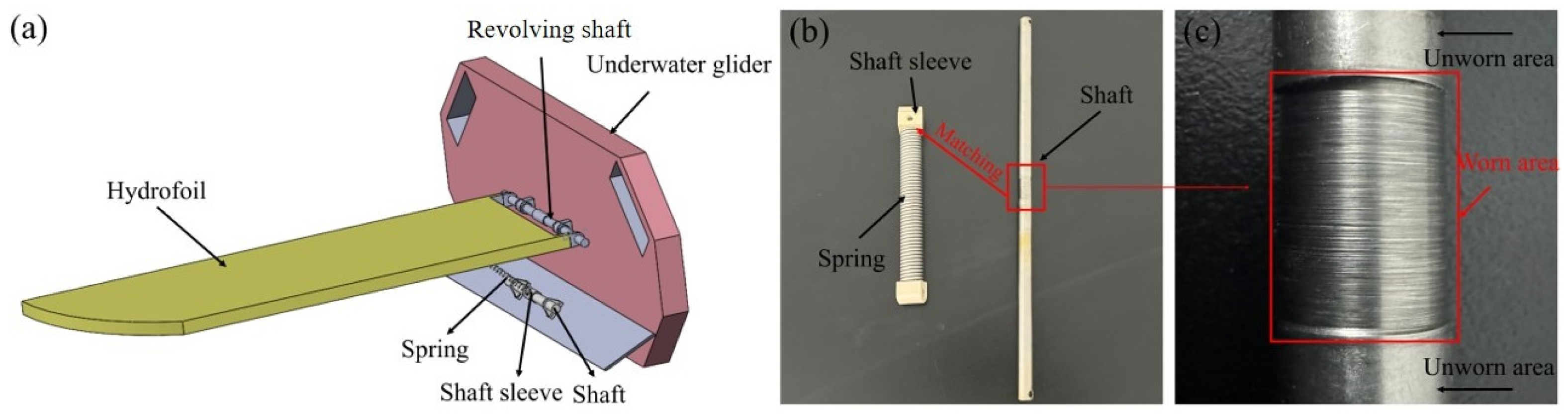
1. Introduction
2. Materials and Methods
2.1. Preparation of the Materials and Friction Pairs
2.2. Preparation of Natural Seawater
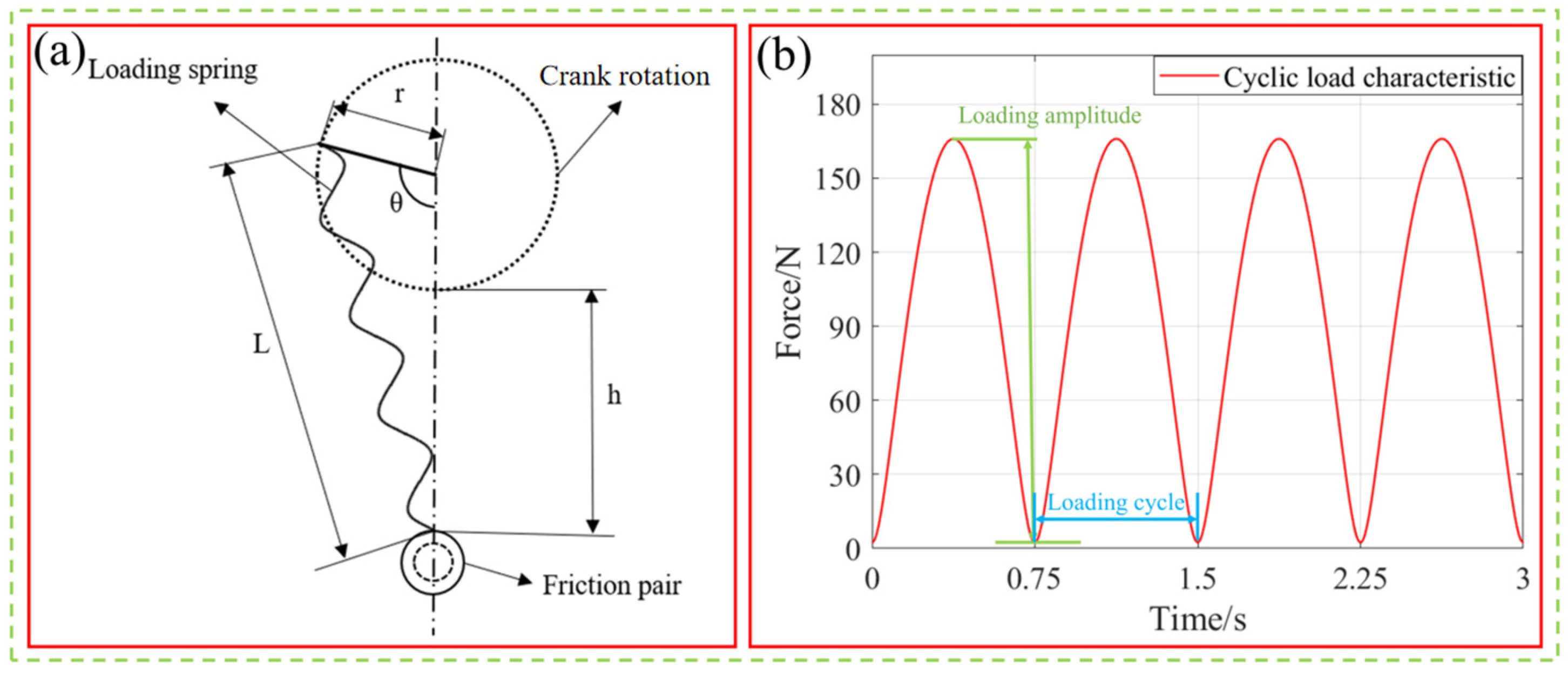
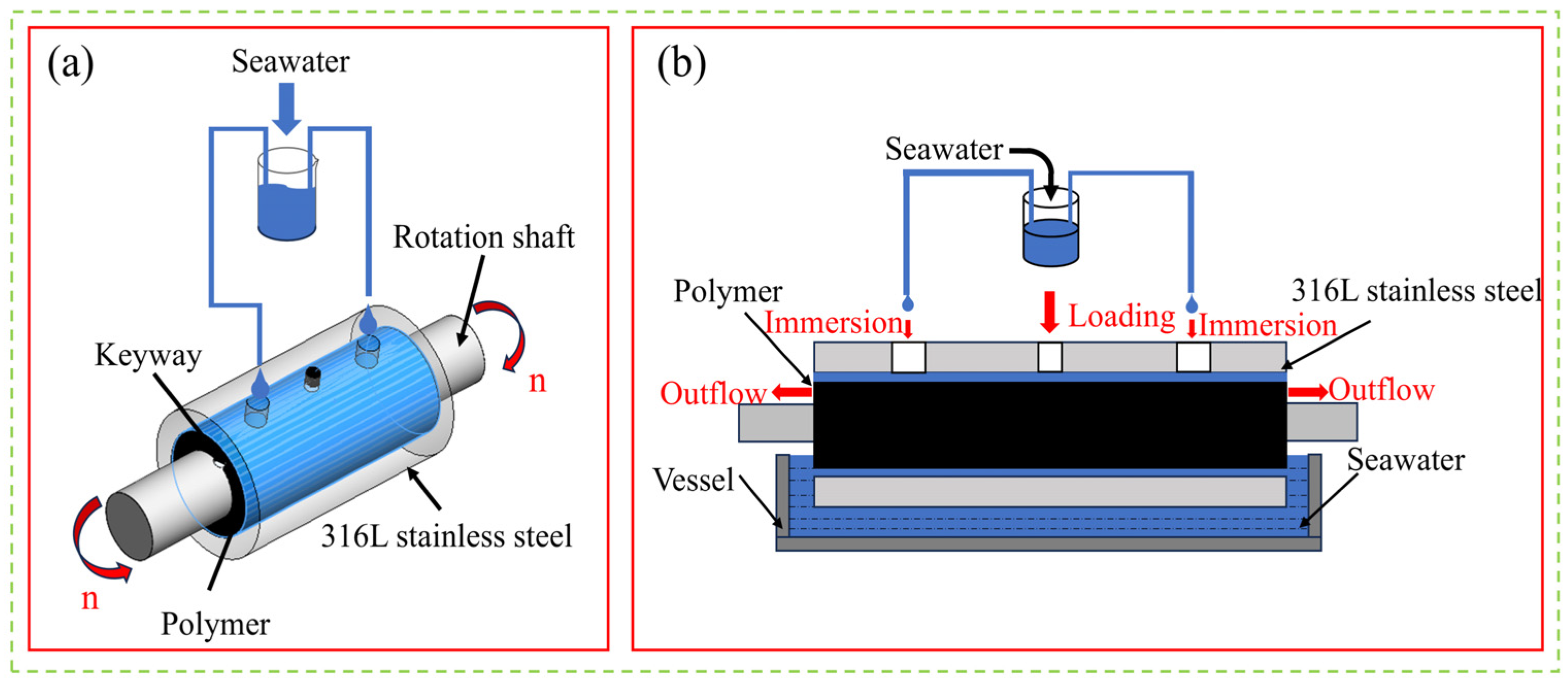
2.3. Test Equipment and Principle
2.4. Experimental Methods
2.4.1. Water Absorption Tests
2.4.2. Mechanical Property Tests
2.4.3. Friction and Wear Tests
3. Results
3.1. Analysis of the Water Absorption Results
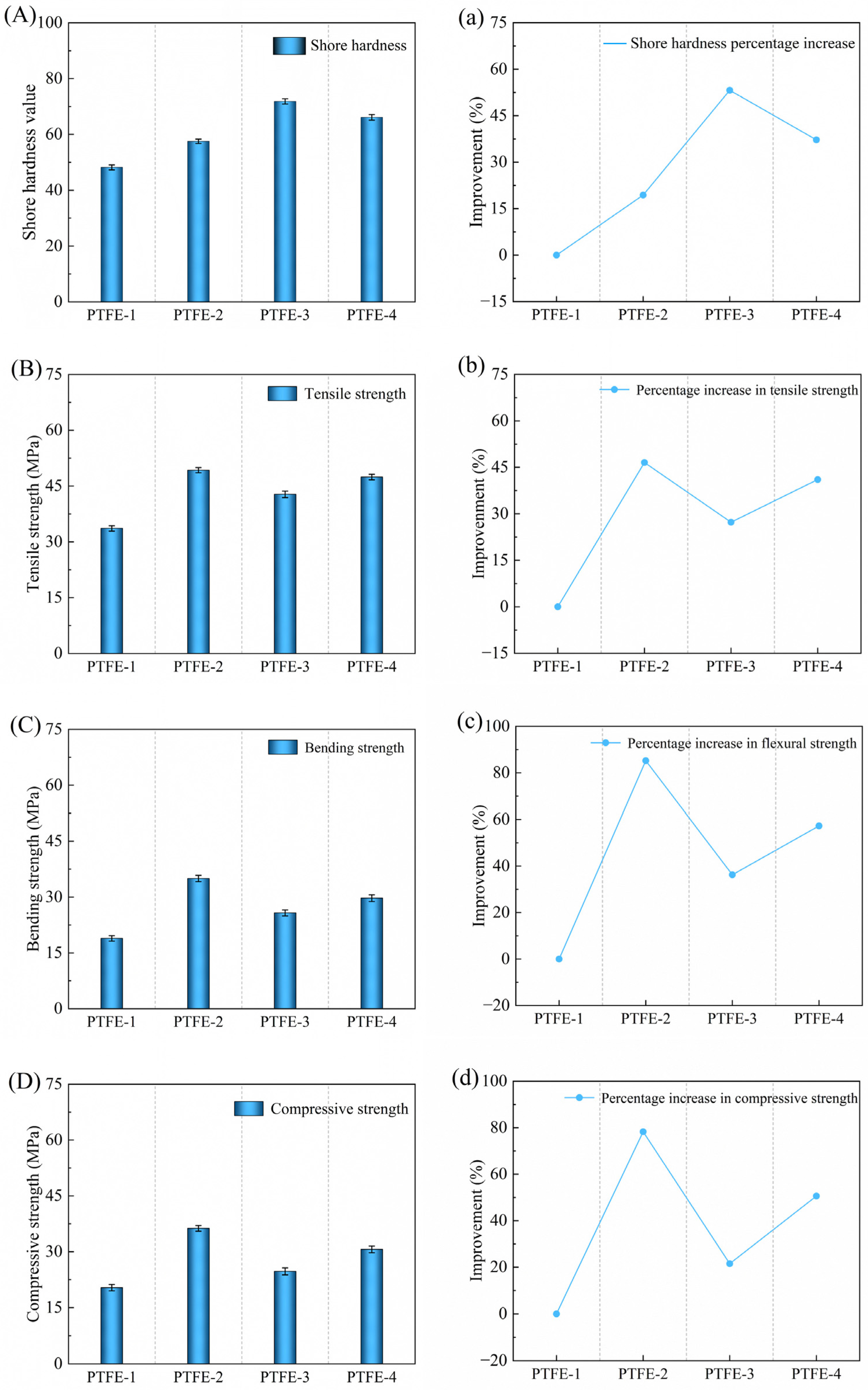
3.2. Analysis of Mechanical Property Test Results
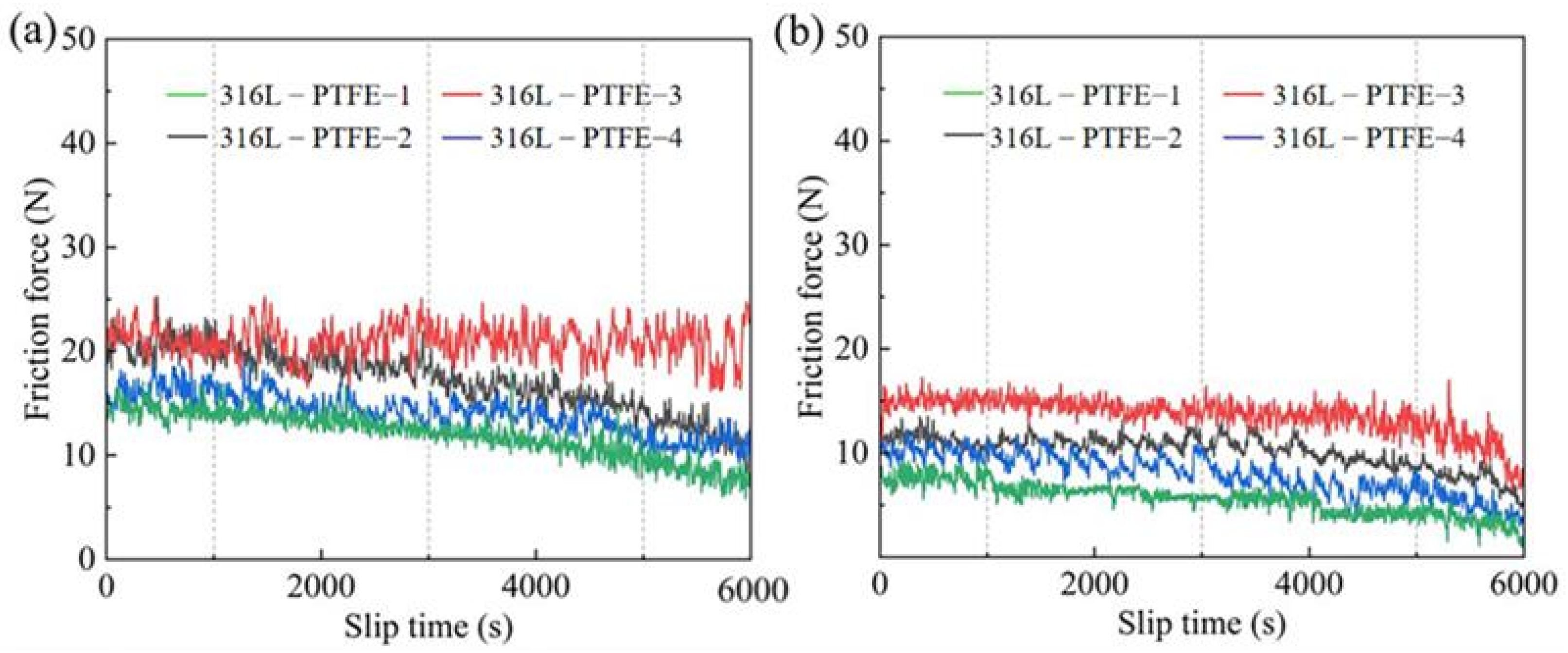
3.3. Analysis of the Friction and Wear Test Results
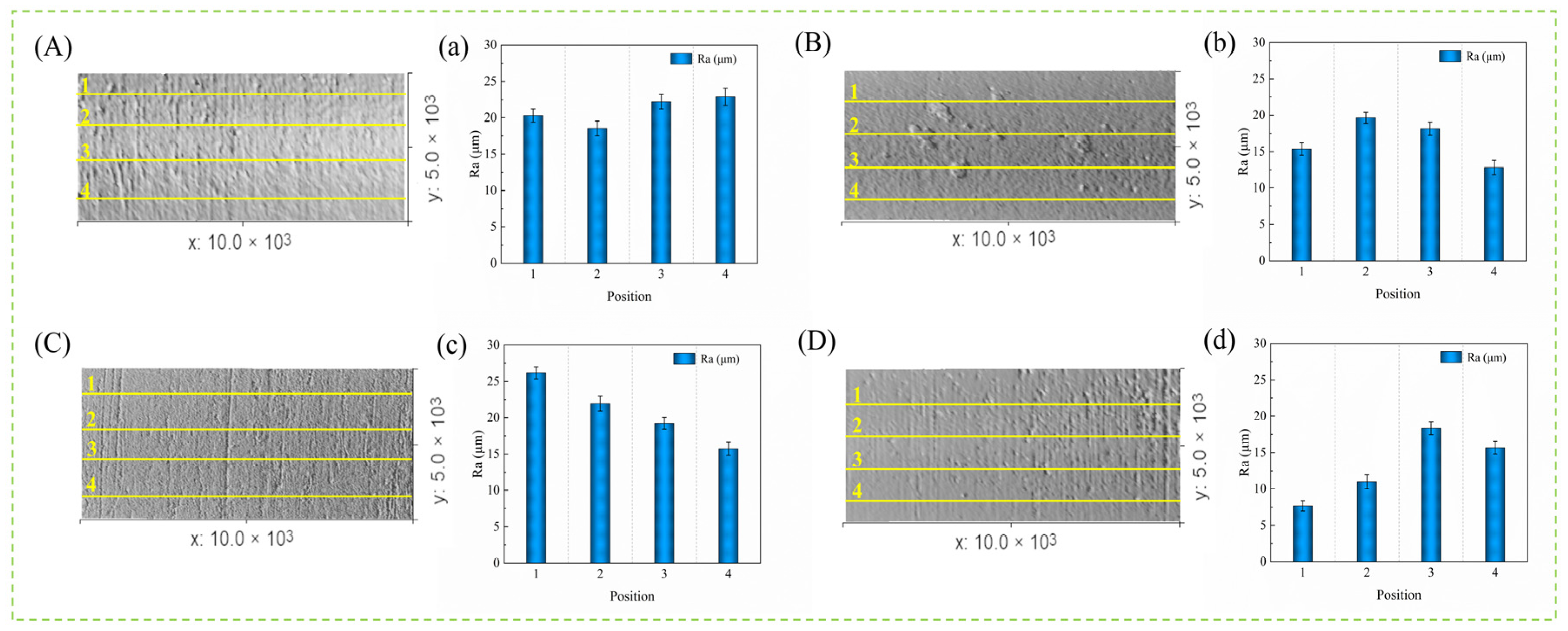
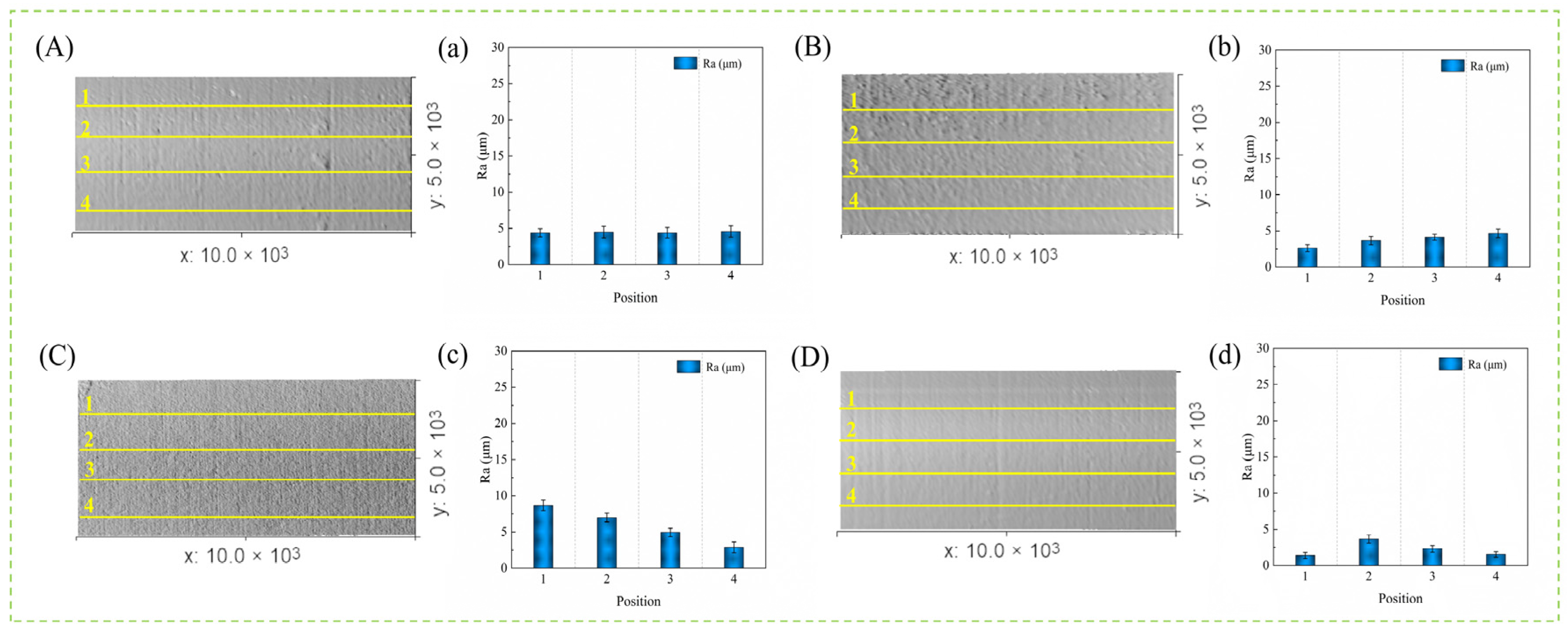
3.4. Three-Dimensional Wear Topography Analysis
3.5. Wear Morphology Analysis
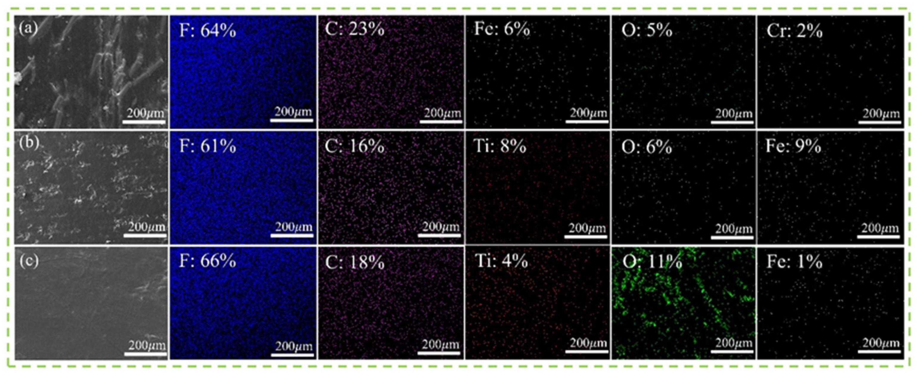
3.6. EDS Analysis
4. Discussion
4.1. Effects of the Binding Properties of the Fibers and Matrix on Seawater Permeability
4.2. Synergistic Enhancement Effects and Lubrication Effects of Ti-C/CFs and Seawater on PTFE
4.3. Stability of Enhanced Filler–Substrate Long-Term Adhesion in Marine Environments and the Effects of Radiation and Surface Treatment on Its Performance
5. Conclusions
Author Contributions
Funding
Data Availability Statement
Acknowledgments
Conflicts of Interest
Abbreviations
| CAC | Constant amplitude cyclic |
| PTFE | Polytetrafluoroethylene |
| CF | Carbon fiber |
| Ti-C | Titanium carbide |
References
- Wood, R.J.K. Marine wear and tribocorrosion. Wear 2017, 376, 893–910. [Google Scholar] [CrossRef]
- Sun, X.; Ma, S.; Sang, H.; Li, C.; Liu, J. Research on the propulsion performance of spring-hydrofoil mechanism of the wave glider. Ocean Eng. 2022, 266, 112709. [Google Scholar] [CrossRef]
- Singh, Y.; Bhattacharyya, S.; Idichandy, V.G. CFD approach to modelling, hydrodynamic analysis and motion characteristics of a laboratory underwater glider with experimental results. J. Ocean Eng. Sci. 2017, 2, 90–119. [Google Scholar] [CrossRef]
- Zhang, S.; Sang, H.; Sun, X.; Liu, F.; Zhou, Y.; Yu, P. A multi-objective path planning method for the wave glider in the complex marine environment. Ocean Eng. 2022, 264, 112481. [Google Scholar] [CrossRef]
- Litwin, W.; Dymarski, C. Experimental research on water-lubricated marine stern tube bearings in conditions of improper lubrication and cooling causing rapid bush wear. Tribol. Int. 2016, 95, 449–455. [Google Scholar] [CrossRef]
- Urbahs, A.; Savkovs, K.; Rijkuris, G.; Andrejeva, D. Corrosion and wear analysis in marine transport constructions. Transp. Aerosp. Eng. 2018, 6, 5–14. [Google Scholar] [CrossRef]
- Zhao, Z.; Huang, Q.; Sheng, M. The influence of local wear and contact roughness on mixed lubrication of marine stern bearing with misaligned shaft. Lubr. Sci. 2023, 35, 498–512. [Google Scholar] [CrossRef]
- Liu, F.; Chang, Z.; Zhang, S.; Sun, X.; Sang, H.; Wang, X.; Ma, S. The maneuverability analysis of the wave glider with a propeller-rudder system. Ocean Eng. 2024, 294, 116782. [Google Scholar] [CrossRef]
- Feng, Z.; Chang, Z.; Deng, C.; Zhao, L.; Chen, J.; Zhang, J.; Zheng, Z. Effects of nonlinearity of restoring springs on propulsion performance of wave glider. Nonlinear Dyn. 2022, 108, 2007–2022. [Google Scholar] [CrossRef]
- Carter, B.H.; Green, D. Marine lubricants. In Chemistry and Technology of Lubricants; Springer: Dordrecht, The Netherlands, 2010; pp. 389–409. [Google Scholar] [CrossRef]
- Rae, P.J.; Dattelbaum, D.M. The properties of poly (tetrafluoroethylene)(PTFE) in compression. Polymer 2004, 45, 7615–7625. [Google Scholar] [CrossRef]
- Litwin, W. Marine propeller shaft bearings under low-speed conditions: Water vs. oil lubrication. Tribol. Trans. 2019, 62, 839–849. [Google Scholar] [CrossRef]
- Wang, S.; Li, P.; Li, Q. Tribological behaviors of polytetrafluoroethylene composites under dry sliding and seawater lubrication. J. Appl. Polym. Sci. 2013, 130, 2523–2531. [Google Scholar] [CrossRef]
- Chen, B.; Wang, J.; Yan, F. Comparative investigation on the tribological behaviors of CF/PEEK composites under sea water lubrication. Tribol. Int. 2012, 52, 170–177. [Google Scholar] [CrossRef]
- Yuan, W.; Yao, X.; Guo, Q.; Li, C.; Chi, B.; Yu, J. Tribological Performance of Shaft and Surface Pairs with PPS and its Composites in Seawater under Cyclic Loading. Tribol. Lett. 2024, 72, 98. [Google Scholar] [CrossRef]
- Zhang, J.; Lin, G.; Vaidya, U.; Wang, H. Past, present and future prospective of global carbon fibre composite developments and applications. Compos. Part B Eng. 2023, 250, 110463. [Google Scholar] [CrossRef]
- Kumar, S.; Saha, A. Effects of particle size on structural, physical, mechanical and tribology behaviour of agricultural waste (corncob micro/nano-filler) based epoxy biocomposites. J. Mater. Cycles Waste Manag. 2022, 24, 2527–2544. [Google Scholar] [CrossRef]
- Chen, B.; Wang, J.; Yan, F. Friction and Wear Behaviors of Several Polymers Sliding Against GCr15 and 316 Steel Under the Lubrication of Sea Water. Tribol. Lett. 2011, 42, 17–25. [Google Scholar] [CrossRef]
- Tu, F.; Wang, B.; Zhao, S.; Liu, M.; Zheng, J.; Li, Z.; Hu, C.; Jiang, T.; Zhang, Q. Synergistic Enhancement Effect of Polytetrafluoroethylene and WSe2 on the Tribological Performance of Polyetherimide Composites. Lubricants 2025, 13, 44. [Google Scholar] [CrossRef]
- Raut, A.; Nunez, E.E.; Sellers, R.; Rahman, M.S.; Polycarpou, A.A. The effect of reinforcing fillers on the tribological performance of PTFE composites for a sustainable environment. Wear 2024, 556, 205524. [Google Scholar] [CrossRef]
- Goyal, R.; Yadav, M. Study on wear and friction behavior of graphite flake-filled PTFE composites. J. Appl. Polym. Sci. 2013, 127, 3186–3191. [Google Scholar] [CrossRef]
- Wang, S.; Song, W.; An, L.; Xia, Z.; Zhang, S. Fabrication and Tribology Properties of PTFE-Coated Cemented Carbide Under Dry Friction Conditions. Lubricants 2024, 12, 363. [Google Scholar] [CrossRef]
- de Viteri, V.S.; Barandika, G.; Bayón, R.; Fernández, X.; Ciarsolo, I.; Igartua, A. Development of Ti-C-N coatings with improved tribological behavior and antibacterial properties. J. Mech. Behav. Biomed. Mater. 2016, 55, 75–86. [Google Scholar] [CrossRef] [PubMed]
- Kao, W.; Su, Y.; Horng, J.; Huang, H.; Yang, S. Improved tribological, electrochemical and biocompatibility properties of Ti6Al4V alloy by gas-nitriding and Ti-C: H coating. Surf. Coat. Technol. 2015, 283, 70–79. [Google Scholar] [CrossRef]
- Sadeghi, N.; Aghajani, H.; Akbarpour, M.R. Microstructure and tribological properties of in-situ TiC-C/Cu nanocomposites synthesized using different carbon sources (graphite, carbon nanotube and graphene) in the Cu-Ti-C system. Ceram. Int. 2018, 44, 22059–22067. [Google Scholar] [CrossRef]
- Cheng, Y.; Browne, T.; Heckerman, B.; Meletis, E. Influence of the C content on the mechanical and tribological properties of the TiCN coatings deposited by LAFAD technique. Surf. Coat. Technol. 2011, 205, 4024–4029. [Google Scholar] [CrossRef]
- ISO 178-2010; Plastics-Determination of Flexural Properties. International Organization for Standardization: Geneva, Switzerland, 2010.
- Yuan, W.; Dong, G.; Guo, Q.; Sui, W.; Zhang, L. Tribological performance of differential gear end-face sliding on washer with a radial groove. Eng. Fail. Anal. 2018, 85, 126–136. [Google Scholar] [CrossRef]
- ASTM D2240:2015; Standard Test Method for Rubber Property-Durometer Hardness. ASTM International: West Conshohocken, PA, USA, 2015.
- ASTM D638-14:2014; Standard Test Method for Tensile Properties of Plastics. ASTM International: West Conshohocken, PA, USA, 2014.
- ASTM D790:2017; Standard Test Methods for Flexural Properties of Unreinforced and Reinforced Plastics and Electrical Insulating Materials. ASTM International: West Conshohocken, PA, USA, 2017.
- ASTM D695-15; Standard Test Method for Compressive Properties of Rigid Plastics. ASTM International: West Conshohocken, PA, USA, 2024.
- Johansson, P.; Marklund, P.; Björling, M.; Shi, Y. Effect of Oxygen and Moisture on the Friction and Wear of Carbon Fiber-Reinforced Polymers. Lubricants 2023, 11, 412. [Google Scholar] [CrossRef]
- Hu, M.; Liu, X.; Zhou, C.; Wang, D.; Xiao, Q.; Guan, X.; Zhang, S.; Xu, Z. Comparative study of the current-carrying tribological properties of carbon graphite composites with different hardnesses. Int. J. Mech. Sci. 2023, 245, 108133. [Google Scholar] [CrossRef]
- Wang, Q.; Song, F.; Zhang, X.; Zhao, X.; Zhao, G.; Wang, T. Impact of fillers and counterface topography on wear behavior of PTFE polymers for ultrasonic motor. J. Appl. Polym. Sci. 2017, 134, 19. [Google Scholar] [CrossRef]
- Homayoun, M.R.; Golchin, A.; Emami, N. Effect of hygrothermal ageing on tribological behaviour of PTFE-based composites. Lubricants 2018, 6, 103. [Google Scholar] [CrossRef]
- Li, H.; Zhang, K.; Fan, X.; Cheng, H.; Xu, G.; Suo, H. Effect of seawater ageing with different temperatures and concentrations on static/dynamic mechanical properties of carbon fiber reinforced polymer composites. Compos. Part B Eng. 2019, 173, 106910. [Google Scholar] [CrossRef]
- Wang, J.; Chen, B.; Liu, N.; Han, G.; Yan, F. Combined effects of fiber/matrix interface and water absorption on the tribological behaviors of water-lubricated polytetrafluoroethylene-based composites reinforced with carbon and basalt fibers. Compos. Part A Appl. Sci. Manuf. 2014, 59, 85–92. [Google Scholar] [CrossRef]
- Gheisari, R.; Polycarpou, A.A. Three-body abrasive wear of hard coatings: Effects of hardness and roughness. Thin Solid Film. 2018, 666, 66–75. [Google Scholar] [CrossRef]
- Huang, L.; Deng, X.; Li, C.; Jia, Y.; Wang, Q.; Wang, Z. Effect of TiC particles on three-body abrasive wear behaviour of low alloy abrasion-resistant steel. Wear 2019, 434, 202971. [Google Scholar] [CrossRef]
- Wang, W.; Yuan, W.; Guo, Q.; Chi, B.; Yin, F.; Wang, N.; Yu, J. Tribological properties of ductile cast iron with in-situ textures created through abrasive grinding and laser surface ablation. Tribol. Int. 2024, 200, 110134. [Google Scholar] [CrossRef]
- Tsenoglou, C.J.; Pavlidou, S.; Papaspyrides, C.D. Evaluation of interfacial relaxation due to water absorption in fiber-polymer composites. Compos. Sci. Technol. 2006, 66, 2855–2864. [Google Scholar] [CrossRef]
- Li, X.; Chen, L.; Zhang, W.; Lv, X.; Huo, S.; Wang, Y.; Zhou, Y. Influence of TiC content on microstructure and mechanical properties of (Ta, Ti) C ceramics. Int. J. Refract. Met. Hard Mater. 2023, 110, 106031. [Google Scholar] [CrossRef]
- Xian, G.; Wang, Z.; Kong, D.; Dong, S.; Li, C.; Hong, B. Degradation of an underwater epoxy adhesive and its bonding to steel subjected to water or seawater immersion. Int. J. Adhes. Adhes. 2024, 132, 103711. [Google Scholar] [CrossRef]
- Niu, R.; Yang, Y.; Liu, Z.; Ding, Z.; Peng, H.; Fan, Y. Durability of Two Epoxy Adhesive BFRP Joints Dipped in Seawater under High Temperature Environment. Polymers 2023, 15, 3232. [Google Scholar] [CrossRef]
- Bartosova, L.; Kohutiar, M.; Krbata, M.; Escherova, J.; Eckert, M.; Jus, M. The Influence of Accelerated Electron Irradiation on the Change of Tribological Behavior of Polymeric Materials PET, PTFE & PE2000C. Manuf. Technol. 2023, 23, 589–596. [Google Scholar] [CrossRef]
- Kohutiar, M.; Janík, R.; Krbata, M.; Bartosova, L.; Jus, M.; Timárová, Ľ. Study of the effect of pretreatment of 3D printed PLA filament modified by plasma discharge and changes in its dynamic-mechanical properties. Manuf. Technol. 2023, 23, 461–467. [Google Scholar] [CrossRef]


| Properties | Values |
|---|---|
| Density (g/cm3) | 8.03 |
| Elasticity modulus (GPa) | 206 |
| Brinell hardness (HB) | 230 |
| Elongation (%) | 30 |
| Heat conductivity coefficient (W/(m·k)) | 16.3 |
| Thermal expansivity (10−6·°C) | 16.0 |
| Tensile strength (MPa) | 620 |
| Yield strength (MPa) | 310 |
| Composition | C | Si | Mn | P | S | Gr | Ni | Mo |
|---|---|---|---|---|---|---|---|---|
| Content (wt.%) | ≤0.030 | ≤1.00 | ≤2.00 | ≤0.035 | ≤0.030 | 16.00 ~18.00 | 10.00 ~14.00 | 2.00 ~3.00 |
| Compound | NaCl | MgCl2 | Na2SO4 | NaHCO3 | KBr | H3BO3 | SrCl2 | NaF | CaCl2 |
|---|---|---|---|---|---|---|---|---|---|
| Concentration /(g/L) | 24.95 | 5.77 | 4.52 | 0.221 | 0.196 | 0.044 | 0.031 | 0.005 | 1.34 |
| Parameters | Loading Spring |
|---|---|
| Length | 130 mm |
| Wire diameter | 1.5 mm |
| Spring diameter | 15 mm |
| Spring coil number | 64 |
| Stiffness | 0.64 N/mm |
| Vibration period | 0.75 s |
| Time (h) | Water Absorption ( g/cm2) | |||
|---|---|---|---|---|
| PTFE-1 | PTFE-2 | PTFE-3 | PTFE-4 | |
| 4 | 3.64 | 27.61 | 97.33 | 17.95 |
| 8 | 4.79 | 49.26 | 186.39 | 28.64 |
| 12 | 5.28 | 61.32 | 271.41 | 35.87 |
| 16 | 6.97 | 77.97 | 345.65 | 44.15 |
| 20 | 8.42 | 89.43 | 448.17 | 59.26 |
| 24 | 9.12 | 112.54 | 541.72 | 67.31 |
| Rise (%) | 150.55 | 303.22 | 456.58 | 274.99 |
| Time (h) | PTFE-1 | PTFE-2 | PTFE-3 | PTFE-4 | ||||
|---|---|---|---|---|---|---|---|---|
| Weight (g) | Augment (%) | Weight (g) | Augment (%) | Weight (g) | Augment (%) | Weight (g) | Augment (%) | |
| 0 | 31.27 | 0 | 32.28 | 0 | 33.89 | 0 | 32.81 | 0 |
| 4 | 31.281 | 0.035 | 32.37 | 0.28 | 34.22 | 0.97 | 32.87 | 0.18 |
| 8 | 31.285 | 0.045 | 32.44 | 0.49 | 34.52 | 1.86 | 32.91 | 0.31 |
| 12 | 31.287 | 0.054 | 32.48 | 0.62 | 34.81 | 2.71 | 32.93 | 0.37 |
| 16 | 31.292 | 0.071 | 32.53 | 0.77 | 35.06 | 3.45 | 32.95 | 0.43 |
| 20 | 31.296 | 0.083 | 32.57 | 0.89 | 35.41 | 4.49 | 33.01 | 0.61 |
| 24 | 31.299 | 0.093 | 32.64 | 1.16 | 35.73 | 5.43 | 33.03 | 0.67 |
| Samples | Before Seawater Immersion | After Seawater Immersion | Decrease (%) |
|---|---|---|---|
| Shore hardness | |||
| PTFE-1 | 48.19 ± 0.53 | 47.44 ± 0.63 | 1.58 |
| PTFE-2 | 57.53 ± 0.61 | 56.22 ± 0.57 | 2.33 |
| PTFE-3 | 73.83 ± 0.69 | 70.29 ± 0.63 | 5.04 |
| PTFE-4 | 66.12 ± 0.74 | 64.77 ± 0.69 | 2.08 |
| Tensile strength (MPa) | |||
| PTFE-1 | 33.62 ± 0.72 | 33.21 ± 0.74 | 1.23 |
| PTFE-2 | 49.27 ± 0.58 | 48.33 ± 0.65 | 1.94 |
| PTFE-3 | 42.79 ± 0.49 | 38.84 ± 0.75 | 10.17 |
| PTFE-4 | 47.42 ± 0.41 | 46.77 ± 0.56 | 1.39 |
| Flexural strength (MPa) | |||
| PTFE-1 | 18.89 ± 0.52 | 18.63 ± 0.39 | 1.39 |
| PTFE-2 | 34.99 ± 0.67 | 33.76 ± 0.46 | 3.64 |
| PTFE-3 | 25.74 ± 0.43 | 23.41 ± 0.61 | 9.95 |
| PTFE-4 | 29.71 ± 0.81 | 29.15 ± 0.68 | 1.92 |
| Compressive strength (MPa) | |||
| PTFE-1 | 20.34 ± 0.71 | 19.98 ± 0.63 | 1.81 |
| PTFE-2 | 36.26 ± 1.02 | 35.06 ± 0.81 | 3.42 |
| PTFE-3 | 24.71 ± 0.86 | 22.19 ± 0.93 | 11.36 |
| PTFE-4 | 30.63 ± 0.79 | 29.82 ± 1.07 | 2.72 |
Disclaimer/Publisher’s Note: The statements, opinions and data contained in all publications are solely those of the individual author(s) and contributor(s) and not of MDPI and/or the editor(s). MDPI and/or the editor(s) disclaim responsibility for any injury to people or property resulting from any ideas, methods, instructions or products referred to in the content. |
© 2025 by the authors. Licensee MDPI, Basel, Switzerland. This article is an open access article distributed under the terms and conditions of the Creative Commons Attribution (CC BY) license (https://creativecommons.org/licenses/by/4.0/).
Share and Cite
Yan, A.; Yao, X.; Wei, Y.; Guo, Q.; Wang, Y.; Tang, W.; Xu, X. Ti-C and CFs Work Together to Enhance the Comprehensive Tribological Properties of PTFE-Based Composites for the Manufacture of Wave Glider Power Shafts. Lubricants 2025, 13, 277. https://doi.org/10.3390/lubricants13070277
Yan A, Yao X, Wei Y, Guo Q, Wang Y, Tang W, Xu X. Ti-C and CFs Work Together to Enhance the Comprehensive Tribological Properties of PTFE-Based Composites for the Manufacture of Wave Glider Power Shafts. Lubricants. 2025; 13(7):277. https://doi.org/10.3390/lubricants13070277
Chicago/Turabian StyleYan, Angang, Xingju Yao, Yuan Wei, Qianjian Guo, Yulong Wang, Wuqiang Tang, and Xian Xu. 2025. "Ti-C and CFs Work Together to Enhance the Comprehensive Tribological Properties of PTFE-Based Composites for the Manufacture of Wave Glider Power Shafts" Lubricants 13, no. 7: 277. https://doi.org/10.3390/lubricants13070277
APA StyleYan, A., Yao, X., Wei, Y., Guo, Q., Wang, Y., Tang, W., & Xu, X. (2025). Ti-C and CFs Work Together to Enhance the Comprehensive Tribological Properties of PTFE-Based Composites for the Manufacture of Wave Glider Power Shafts. Lubricants, 13(7), 277. https://doi.org/10.3390/lubricants13070277