Abstract
In additive–subtractive hybrid manufacturing (ASHM), machining and additive processes are combined in a single operation to merge the benefits of both. This method faces challenges, especially during the machining steps. Parts made through additive manufacturing often have low machinability due to factors like residual stresses and fine, hard microstructures. In ASHM, intermediate heat treatments are not possible, leading to the increased hardness of the printed material. Cutting fluids, typically used to reduce temperature and friction, can contaminate the build environment and impair layer adhesion; therefore, they are not recommended in ASHM. This study investigates soft metallic lubricant coatings in ASHM as substitutes for conventional fluid lubricants during dry machining. The coatings form a lubricating layer between the tool and workpiece, providing an alternative to cutting fluids. This research evaluates their effectiveness in improving the surface integrity of additively manufactured parts and supporting dry machining. The results of our research show a 65% reduction in force, a 50% reduction in tool wear, and a reduction in microstructural changes during machining while maintaining dry machining.
1. Introduction
Additive manufacturing has come a long way since 1987, when one of the first additive manufacturing methods was introduced. This method is known as stereolithography (SL) and was initially limited to certain polymers. Nevertheless, the invention of SL opened new opportunities for creating much more complex parts [1]. Since its development, additive manufacturing (AM) has facilitated the production of complex components that were challenging to manufacture with traditional methods. The first additively manufactured part using metal alloy powder was reported in 1990, utilizing selective laser sintering (SLS) technology. Today, the process used for metals is more commonly referred to as selective laser melting (SLM), as it achieves the full melting of the metal powder [2]. Most current metal additive manufacturing systems use powder bed fusion. In this process, thin layers of powder are spread on a build plate, and an energy source (laser or electron beam) fuses the powder according to the desired design. After each layer is completed, a new layer of powder is added, repeating the process until a 3D part is formed. Powder bed fusion includes techniques such as selective laser sintering (SLS), selective laser melting (SLM), direct metal laser sintering (DMLS), direct metal laser melting (DMLM), and electron beam melting (EBM) [3]. Table 1 is provided for a better understanding and comparison of the above-mentioned methods.

Table 1.
This comprehensive table summarizing the above-mentioned AM processes is provided to enhance the readers’ understanding of each process.
Despite advancements in additive manufacturing, challenges remain, such as unsatisfactory surface roughness and internal defects like porosity, cracks, and residual stress between layers. These defects can negatively impact the microstructure and mechanical properties of the parts. As a result, a series of post-processing operations is often necessary to ensure the quality of the final product, enhance mechanical properties, and address defects from the additive manufacturing process. Post-processing is essential to prevent distortions caused by rapid cooling and the remelting of the bottom layer during the deposition and solidification of subsequent layers, leading to thermal cycles in the final part upon the completion of printing. These operations include stress relief, the removal of the part and support structures, and machining [10,14].
There are other challenges with the creation of accurate and flexible designs for components, such as conformal cooling channels, the fabrication of parts without the need for support structures, and also in finishing or machining certain regions of the final printed parts, which are often inaccessible to conventional machining tools.
To address these challenges mentioned above, the additive–subtractive hybrid machine (ASHM) was introduced in 2014, integrating additive manufacturing with 5-axis machining. This method represents a significant advancement in the AM sector and offers multiple benefits. One of the primary advantages is its effectiveness in machining areas that are challenging to machine afterwards. Moreover, it allows for the removal of support structures, potentially using a multi-axis system or jointed-arm robots, also mitigating the requirement for additional processing stages [15]. Furthermore, ASHM has demonstrated effectiveness in reducing additional movements by maintaining the part’s clamping position throughout the process. Consequently, this leads to a decrease in both the time required for product production and material waste [16].
Despite all the benefits of ASHM technology, there are still some challenges associated with additive and machining processes. Each process presents its own specific challenges that require individual attention, along with additional issues arising from integrating these two methods into a single machine, such as the cutting fluid–laser integration. In this paper, we introduce a novel solution that addresses the problems associated with both machining and the joint cutting fluid–laser integration simultaneously.
In general, machining additive manufactured (AM) parts can be more challenging than machining wrought parts due to factors such as anisotropy in mechanical properties and the higher strength and hardness of the material. These characteristics result in significantly increased cutting forces, leading to elevated tool wear and failure, which can adversely affect the surface integrity of the machined parts [17].
Additionally, in ASHM, the use of cutting fluids presents challenges and is often unsuitable, as they can interfere with the simultaneous printing operation. Even if cutting fluids could be implemented, they might cause faster cooling rates, resulting in a more inhomogeneous microstructure that is not desirable. Furthermore, removing excessive cutting fluid from parts by blowing them off, a common practice by some manufacturers, poses significant challenges as the presence of metal powder can create fire and explosion hazards [18].
On the other hand, the dry machining of AM parts requires highly wear- and temperature-resistant tools, which can be quite expensive. Even with such tools, extreme conditions of friction, temperature, and pressure make the machining of difficult-to-cut AM materials, such as AM H13 tool steel, very challenging without lubricants.
Building on our previous innovations and considering the challenges associated with liquid lubricants in these processes, this research introduces the application of our novel solid lubricant coating to address lubrication issues in the ASHM of H13. These new lubricant coatings have demonstrated effectiveness under the extreme conditions encountered during machining, providing a valuable alternative solution for ASHM processes.
In general, solid lubricants exhibit a high degree of thermal stability, making them suitable for demanding operational conditions. This implies that, owing to their intrinsic limited elasticity and lower tendency to evaporate, the frequency of reapplication can be minimized. Studies have indicated that solid lubricants are efficacious in lowering friction and wear, thereby enhancing the operational efficiency and extending the service life of tools. However, our previous review study found that most solid lubricants used in machining, such as MoS2 and graphite, need to be applied in powder form and are carried with water- or oil-based lubricants [19]. Although methods like MQSL are employed to deliver these lubricants and reduce fluid consumption, they remain suboptimal for processes like ASHM.
One of the categories of solid lubricants includes soft metals such as Ag and Au. Soft metals have been used as solid lubricants, mainly in engine bearings. However, their performance has been limited by their melting point, and they have never been used as lubricants in machining, where extreme temperatures and pressures occur. Aramesh recently introduced soft metals as solid lubricants in machining. In their previous work, they observed that specific metallic alloys, such as Al-Si alloys, can be used as solid lubricants in machining operations with significant benefits, including reduced friction, chipping, and workpiece microstructural alterations and improved surface integrity and productivity [20,21].
This discovery could significantly benefit the subtractive aspect of ASHM by eliminating the need for cutting fluids and reducing friction under harsh conditions, resulting in improved surface integrity and lower failure rates. This study seeks to enhance this process by exploring the impact of applying this new class of solid, soft metal lubricant coatings on inserts used in the ASHM of the AISI H13 material. Additionally, our novel in situ coating method was introduced as an effective, simple, and cost-efficient solution for implementation in ASHM, as demonstrated in this study.
Due to the lack of access to an ASHM machine, we mimicked the process in this study by machining a part that was additively manufactured in our previous work using the Laser Powder Bed Fusion (LPBF) technique, followed by a machining step with our new coated tools. For comparison, the results were evaluated against those from dry and wet machining using uncoated tools. The next sections provide a brief overview of the additive manufacturing process of AISI H13 using the LPBF method, followed by detailed machinability analyses that include tool and workpiece characterizations. These sections focus on understanding how the soft metal impacts the surface integrity of the workpiece, which is the main challenge for ASHM. The results include analyses of machining forces, surface integrity, and chip formation. Phase quantification and characterization techniques, such as electron backscatter diffraction (EBSD), X-ray diffraction (XRD), and other methods, are employed for detailed surface characterization.
2. Experimental Procedures
2.1. Laser Powder Bed Fusion (LPBF) Samples
The fabrication of the AISI H13 workpiece has been previously conducted in our institution, and all details of this process can be found in the previous publication [22]. To briefly explain, AISI H13 test samples were made using the LPBF process on an EOS M280 machine (Krailling, Germany) equipped with an Yb-fiber laser system delivering a maximum power of 400 W. A high-purity atmosphere of nitrogen gas was applied to reduce the oxygen content in the build chamber to less than 0.1%, hence reducing oxidation during the melting process. The chemical composition of the powder was determined using ICP-OES digestion, and the results were validated against the ASTM standard for the alloy’s chemical composition, as shown in Table 2.
Table 2.
Comparison of chemical composition of AISI H13 powder according to ASTM and ICP.
AISI H13 tool steel has a propensity to crack, so the build plate was preheated to 200 °C to eradicate the possibility of crack development in the as-built parts. The samples were fabricated directly on the build plate in the direction of the thickness with no support structures and underwent no post-processing procedures. A constant layer thickness of 40 µm, in tandem with a 67° rotation of scanning pattern between subsequent layers and a stripe scanning strategy with a width of 10 mm, was maintained during the LPBF process.
2.2. Machining Setup and Parameters
Machining experiments were conducted using Matswra FX-5 CNC three-axis vertical Japanese milling machine, equipped with a 7.5 kW power capacity and capable of reaching a maximum spindle speed of 28,000 rpm. For the tests, the machine’s tool holder, which accommodates two inserts, was fitted with a single insert. This approach was adopted to facilitate the precise wear measurement of each tool. The radius of the tool holder/insert, defined as the distance from the insert’s cutting edge to the center of the tool holder, was set at 9.525 mm. Furthermore, the specified angles for the insert included a clearance angle of 10°, an axial rake angle of 14.73°, and a radial rake angle of −9.805°. Figure 1 is provided to illustrate the machining setup for this experiment.
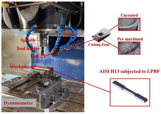
Figure 1.
The machining setup for the experiment. The uncoated tool was treated for pre-machining, which is illustrated in the cutting zone region.
2.3. New Coating Process: Pre-Machining
The lubricant coating used in this study is Al-Si with 8% silicon content, applied using the novel pre-machining technique instead of traditional Physical Vapor Deposition (PVD) for coating the tools. This method has shown superior machining results compared to PVD and is significantly more cost-effective, environmentally friendly, quick, and easy to apply.
In the pre-machining process, as proposed previously by Aramesh [20], a layer of the Al-Si target material is deposited on the tool by machining the target material for a few seconds. The thickness of the coating is approximately 15 microns. The resulting deposited layer on the tool acts mainly as a solid lubricant, reducing friction during the actual machining of the workpiece material. Although the coating thickness may seem high, considering its different working mechanism as a lubricant compared to hard ceramic coatings, a greater thickness is advantageous for this process. The excess coating on the surface is removed along with the chips during the first engagement. However, as demonstrated in our previous FIB-SEM studies, a film of the solid lubricant remains on the tool, providing lubrication throughout its lifespan [23].
The initial coating thickness offers a damping effect and helps prevent the early chipping caused by the high initial machining impact.
The hardness of the coating is around 1.6 GPa, and the coefficient of friction is around 0.1. Due to patent protection, further details, including the cutting regime and parameters, cannot be disclosed.
In this investigation, the cutting conditions for machining the AISI H13 workpieces were purposely pushed to their realistic limits to examine the performance of the suggested treatment under extreme conditions. A very rapid cutting speed of 300 m/min and a comparatively low feed rate and depth of cut were used, as shown in Table 3; given the very small size of additively manufactured samples, several cutting speeds were investigated to determine the speed at which considerable wear results could be obtained given the short cutting length. For comparison, machining tests were also conducted using an uncoated tool under both dry and wet conditions, with industry-standard benchmark cutting fluids. New tools were used for all tests, the cutting conditions were kept consistent, and the same cutting length of 30 mm was maintained.
Table 3.
Cutting condition parameters and settings used for machining of AISI H13.
Tool wear and cutting forces were monitored after each pass; three passes were performed on each tool. Following the machining tests, machinability investigations, including wear surface analyses, microstructural and tribological studies of the worn surfaces, and surface integrity analyses of the machined surfaces, were performed. Cutting forces were quantified using a Kistler 9255B piezoelectric dynamometer (Winterthur, Switzerland), which provides three-channel force measurements (Fx, Fy, Fz). The dynamometer’s output signals were relayed to a data acquisition system via a Kistler 5167A multi-channel amplifier (Winterthur, Switzerland). These signals were then converted into numerical values using Dyno Ware software for analysis. The surface texture, characterized by the parameters Sa and Sz, of the machined surfaces, along with the roughness of the worn area on the tool’s flank face, was evaluated by employing Bruker Alicona InfiniteFocus G5 and Keyence VHX-5000 microscopes. These instruments are equipped with focus variation technology, enabling the precise measurement and analysis of surface characteristics. At least three measurements were taken to ensure consistency in the readings. To assess the characterization of the workpieces, a Tescan Vega II LSU scanning electron microscope (SEM) (Brno, Czech Republic) was used with a 30 kV accelerating voltage, and a JEOL JSM-7000F (Tokyo, Japan) was used with a 20 kV accelerating voltage, a working distance of 15 mm, and a step size of 70 nm. Inverse pole figures, KAM maps, and phase maps were processed using Aztec EDS/EBSD Crystal software (United Kingdom). Residual stresses on the surface of the workpiece were measured using X-ray diffraction (XRD) with LEPTOS software (Germany). Cobalt X-ray radiation with a wavelength of 1.79 Å (Kα) was employed to assess the residual stress of the machined surface.
3. Results and Discussion
3.1. Machining Results
3.1.1. Tool Wear Readings
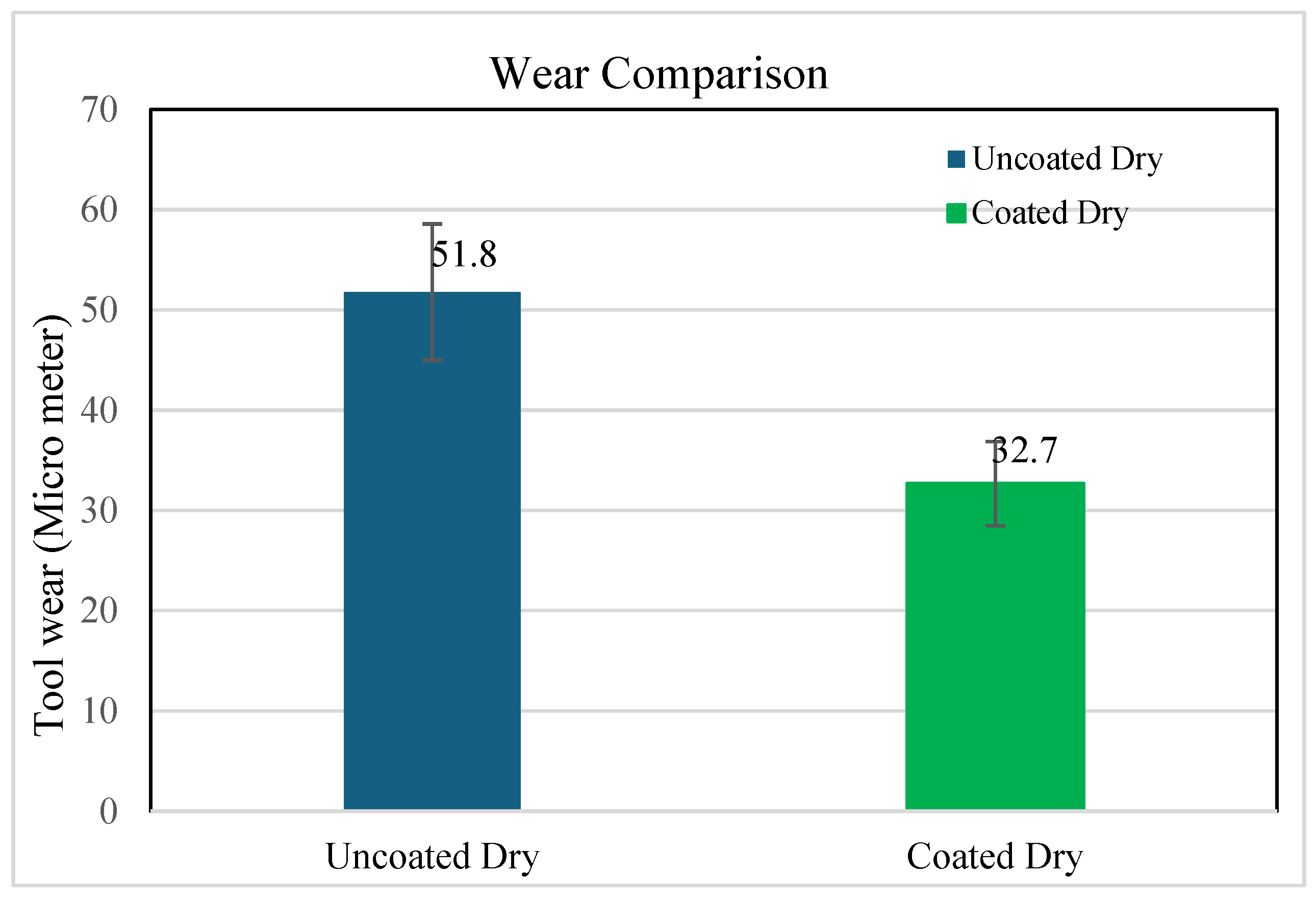
The tool wear readings acquired from the Keyence showed a decrease in tool wear, as illustrated in Figure 2. Significant improvements in tool wear were observed following the application of our lubricant coating, as evidenced by non-overlapping 95% confidence intervals. This decrease can be attributed to the function of Al-Si as a lubricious coating, which resulted in an approximately 50% reduction in tool wear.

Figure 2.
Tool wear readings in microns for uncoated and lubricant-coated tools in dry conditions, with 95% confidence intervals.
Please note that, because the machining was conducted on additively manufactured parts, it was not possible to obtain complete tool wear curves due to material limitations. Based on our previous studies, we expect that the substantial improvements made during the running-in stage will also enhance overall performance.
3.1.2. Force Analysis
The force results are presented in Figure 3. As shown, there was a significant reduction in cutting force when using the Al-Si lubricant coating compared to the uncoated tool under dry conditions. This is supported by the non-overlapping 95% confidence intervals for the coated dry and uncoated dry conditions, indicating a statistically significant difference. After applying the coating, the average force was reduced by approximately 65% compared to dry machining.
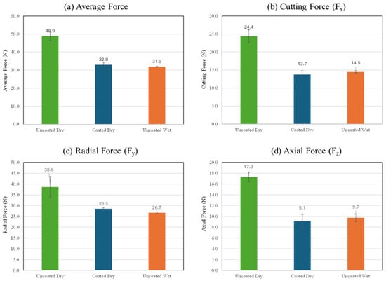
Figure 3.
Force data for uncoated wet, coated dry, and uncoated dry at the cutting speed of 300 m/min: (a) average machining force (b) cutting force, (c) radial force, (d) feed force.
To evaluate the effectiveness of the lubricant coating against benchmark liquid lubricants, an uncoated carbide tool used with flood liquid lubrication was tested using the same machining parameters. The force results are depicted in Figure 3. In Figure 3a, the average machining force of the coated dry condition appeared comparable to that of the uncoated wet condition, often regarded as the conventional lubricated state for reducing machining forces.
The results suggest that the novel coated lubricant is comparable to, and even more effective than, liquid lubrication in flood applications, making it possible to eliminate the need for flood lubrication in the machining process.
When comparing the cutting force based solely on Figure 3b, the coated wet condition demonstrated marginally improved performance relative to the uncoated wet condition. Moreover, there was a substantial reduction in force when compared to the uncoated dry condition, aligning with the primary objective of this research, which is to achieve a force reduction of approximately 45%. The same trend was observed for radial force readings in Figure 3c and feed force readings in Figure 3d, with reductions of approximately 30% and 47%, respectively. The 47% reduction in feed force proved the effectiveness of the lubricant coating in reducing friction during machining.
This reduction in forces can be attributed to the performance of Al-Si as a lubricant coating, resulting in lower friction, reduced contact pressure in the sticking zone under seizure conditions, and enhanced material flow due to Al-Si acting as a lubricious film [21]. Also, it is worth mentioning that Al-Si alloys are known to exhibit force-damping properties [24].
3.2. Surface Integrity Analysis
3.2.1. Surface Analysis
Surface Topography
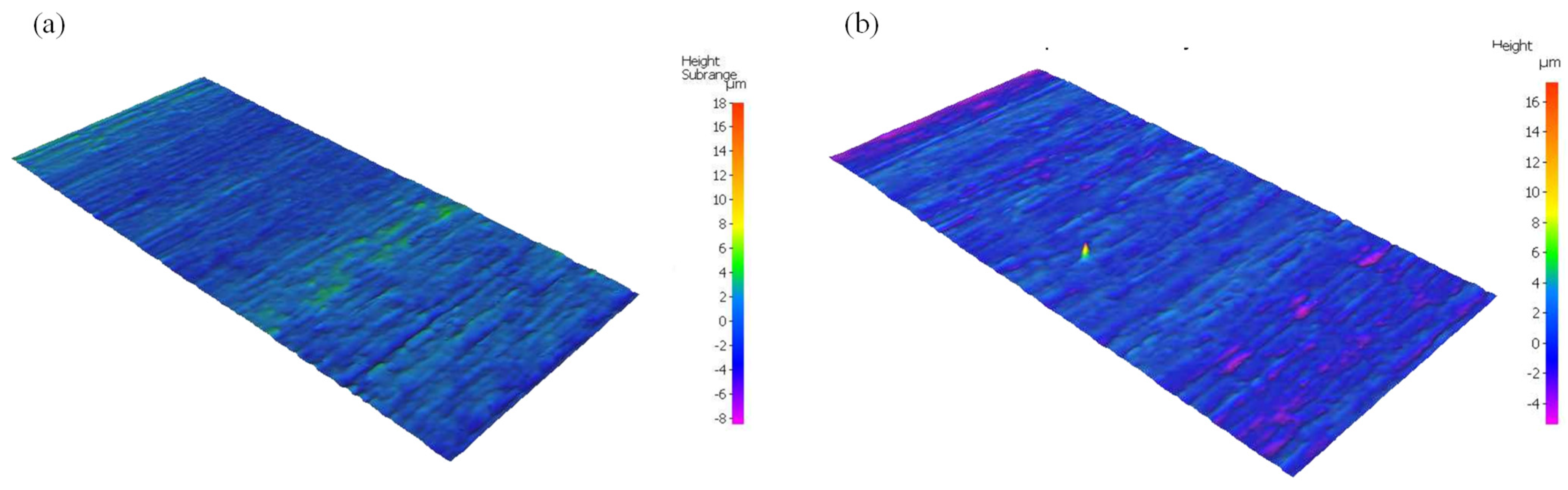
To study the effects of force reduction on the surface integrity of the machined parts, as the first step, optical microscopy analyses were performed on surfaces machined with uncoated and tools coated with our solid lubricant coating using the Alicona InfiniteFocus G5. Due to material limitations and thus the very small cutting lengths, the overall roughness values (Sa) were not considerably different. However, as shown in Figure 4a, the surface machined with our lubricant coating appears to have fewer grooves.

Figure 4.
Surface quality machined with (a) coated tool and (b) uncoated tool.
Surface Roughness
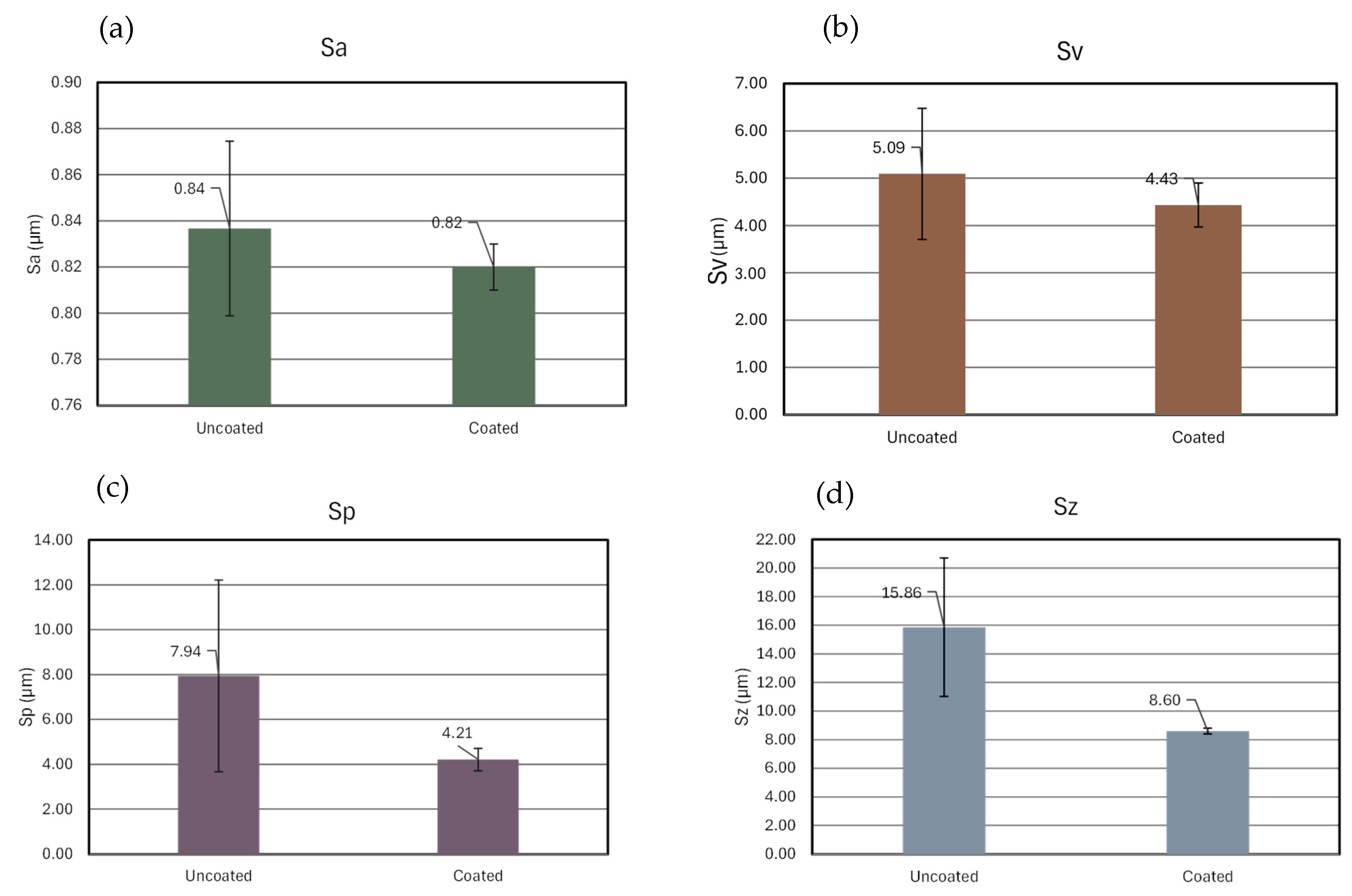
The presence of deeper grooves and higher irregularities is also reflected in the corresponding roughness parameters of the two surfaces, as illustrated in Figure 5. The results were obtained by averaging three measurements taken from three different areas. The surface texture parameters that were used are Sa (Arithmetic Mean Height), Sv (Maximum Velley Depth), Sp (Maximum Peak Height), and Sz (Maximum Peak-to-Valley Height). The average values and standard deviations for the surface machined with the uncoated tool were notably higher than those for the surface machined with our lubricant-coated tool. This suggests that using our lubricant coating during machining could reduce surface roughness, resulting in a smoother finish. This improvement could be attributed to reduced friction and sticking, contributing to better cutting flow.
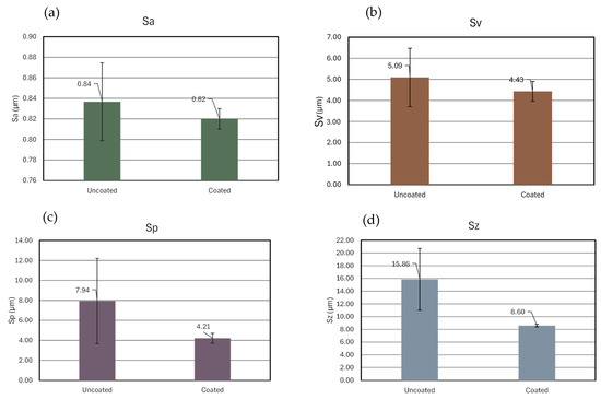
Figure 5.
A comparison of the roughness parameters for surfaces generated with the uncoated tool and coated tools: (a) Sa, (b) Sv, (c) Sp, and (d) Sz.
3.2.2. Subsurface Analysis
EBSD Analysis of Subsurfaces
For an in-depth surface integrity analysis and to study the effects of our solid lubricant on reducing microstructural evolution during machining, EBSD analyses were performed on the machined surfaces using our lubricant-coated tools and uncoated tools, and the results are summarized in this section.
A schematic of the machined sample is shown in Figure 6. The region of interest and direction of cut are depicted in the picture.
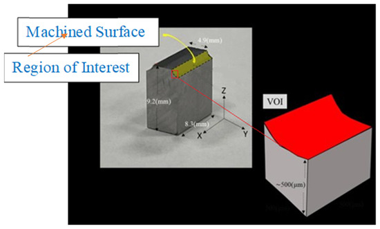
Figure 6.
A schematic of the machined sample.
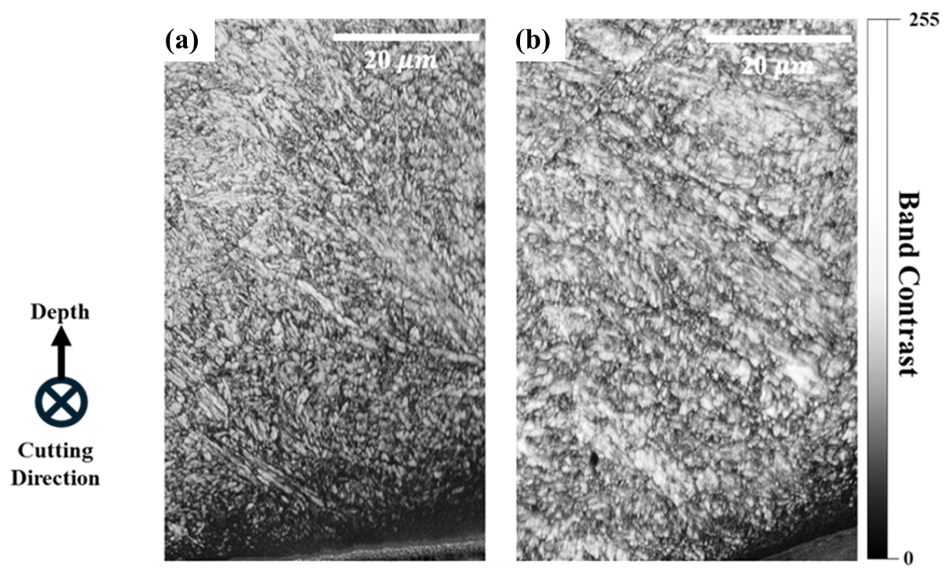
Figure 7 displays the band contrast of machined samples using the two different tools: uncoated and Al-Si-coated tools in dry conditions. The microstructure of both samples appeared to be predominantly martensitic, showing a transition to finer lath sizes closer to the machined surfaces. A high dislocation density is observed on the subsurface of the uncoated sample, appearing as non-indexed regions (the regions with a black matrix near the machined surface) in EBSD [25,26,27]. The coated sample exhibited a thinner layer of severe deformity near the subsurface due to the lower forces and stresses experienced, as seen in Figure 3, which resulted in a shallower affected zone on the machined surface [28].

Figure 7.
Band contrast maps of AISI H13 subsurfaces subjected to LPBF. Cutting direction is illustrated in this figure, and depth direction is also provided. (a) Uncoated sample and (b) coated sample.
Figure 8 presents the kernel average misorientation (KAM) maps for both the uncoated and coated samples. These maps, which illustrate the distribution of localized strain throughout the microstructure based on misorientation angles, reveal that strain localization was significantly more pronounced near the surface areas. The uncoated sample’s strain appeared to be thicker beneath the surface and more widespread in the core compared to the coated sample, where the strain was predominantly restricted to the subsurface. The observation of higher localized strain on the subsurface of the uncoated sample suggests that elevated cutting temperatures resulted in thermally induced damage and altered the strain distribution in the subsurface layer of the workpiece. The temperature increase during the cutting process can alter the material properties and affect the integrity of the subsurface, impacting its physical and mechanical characteristics [29].
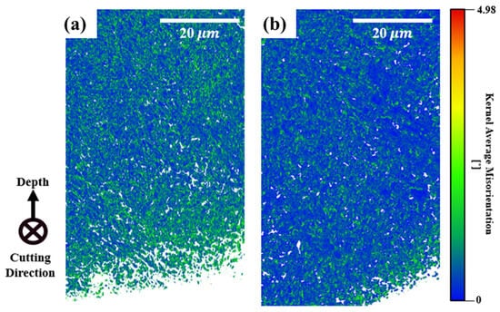
Figure 8.
KAM map presenting strain distribution for (a) uncoated dry and (b) coated dry samples.
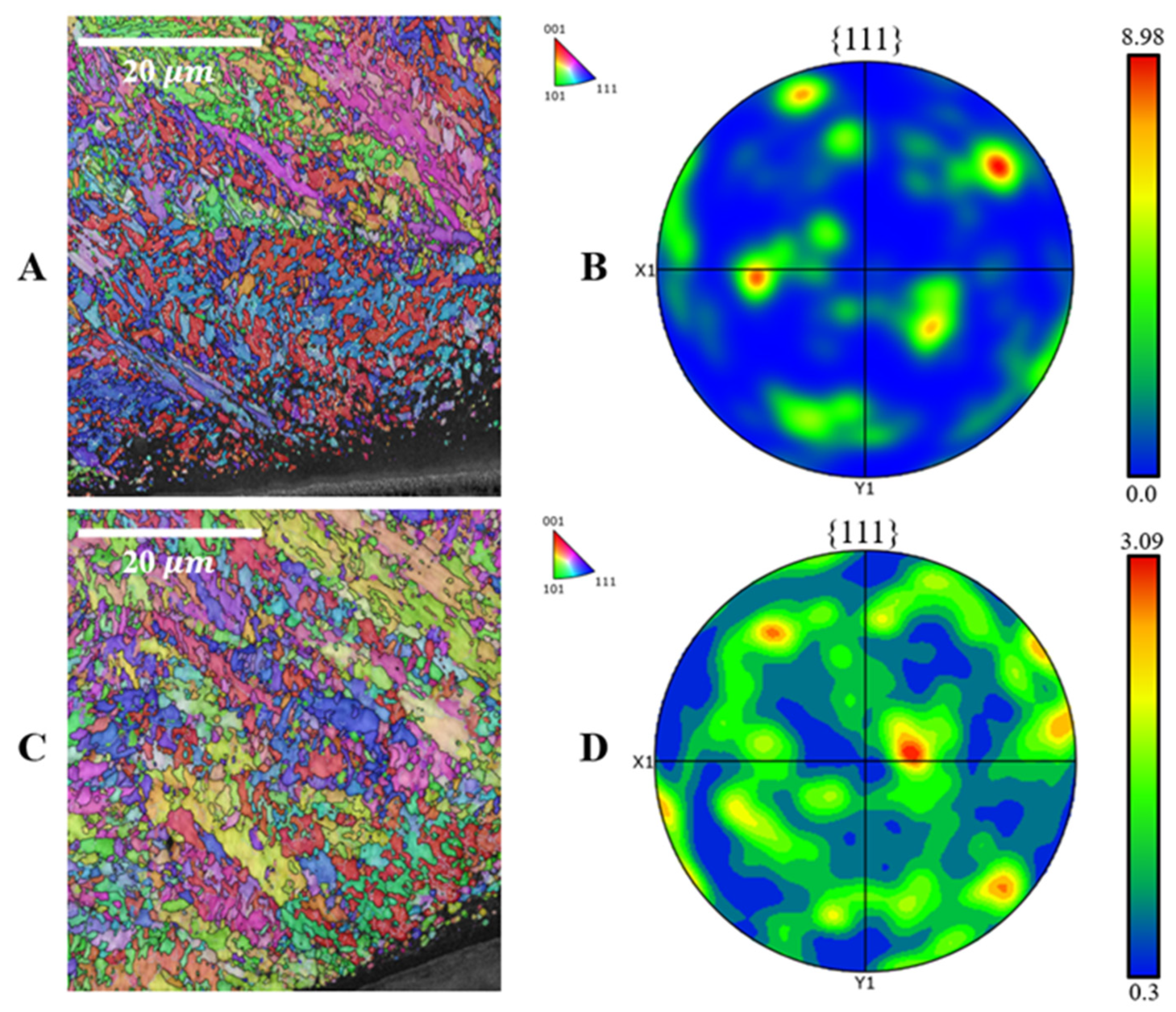
Figure 9A,B show the inverse pole figure (IPF) map of the machined sample along the machining direction. The surface generated using the lubricant-coated tool demonstrated a more random crystallographic texture near the subsurface, which agrees with the pole figure results seen in Figure 9C,D. The maximum intensity of the pole figure was lower for the coated sample at 3.09, compared to the higher intensity of 8.39 for the uncoated sample. The degree of force applied during the machining process (Figure 3) seemed to follow the observed textural changes, with stronger forces leading to a more pronounced cube component post-machining.

Figure 9.
IPF maps and pole figures of AISI H13 subsurfaces subjected to LPBF. (A) Uncoated dry IPF map, (B) coated dry IPF map, (C) uncoated pole figure, and (D) coated pole figure.
XRD Analysis
Supporting previous observations, XRD analysis was performed on the machined samples, and the phase map and XRD results are shown in Figure 10. The results show the distribution of martensite phases within the retained austenite in the microstructures of both samples, revealing a slightly higher fraction of martensite in the uncoated sample, especially close to the machined surface. This observation correlates with the greater intensity of the applied force in the uncoated sample. Stress-induced phase transformation during machining, where austenite transformed to martensite during the machining of AISI H13, has been reported before [30]. External stresses, particularly under uncoated dry conditions, during the post-machining of an additively manufactured part, can encourage the transformation of retained austenite to martensite. Figure 10d shows that the coated dry sample contains 12.04% retained austenite, which is slightly higher than the 10.8% observed in Figure 10b, the uncoated sample.
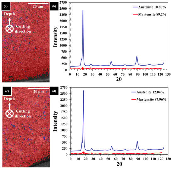
Figure 10.
(a) EBSD phase map of uncoated dry sample, (b) XRD data of uncoated dry sample, (c) EBSD phase map of coated dry sample, and (d) XRD data of coated dry sample.
4. Conclusions
The effectiveness of a soft metal coating (Al-Si) as a solid lubricant in the ASHM process was evaluated through the dry machining of additively manufactured AISI H13. The noticeable improvements in machinability and surface integrity are presented as follows:
- Tool wear analysis indicated a significant 50% decrease in tool wear resulting from the presence of the Al-Si lubricant coating in the cutting zone.
- Force analysis indicated a notable decrease of 65% in the average cutting force.
- SEM and advanced microscopy revealed improved surface characteristics after machining with the Al-Si-coated tool. The treated surface showed reduced groove formation and defect presence, indicating enhanced surface integrity in the final part.
- Extracted EBSD maps were used to examine subsurface integrity under coated and uncoated conditions. The results aligned with machining outcomes. The band contrast map showed higher dislocation density in the uncoated sample, indicating greater deformation near the surface due to increased machining forces.
- The KAM map also demonstrated increased localized strain in the subsurface of the uncoated sample. Interestingly, the affected zone associated with the uncoated tool was not limited to the machined surface but extended to the core.
- An analysis of IPF maps and pole figures showed a more random crystallographic texture at the subsurface in the coated sample, with a lower maximum intensity than that of the uncoated one. This suggests that higher machining forces lead to more pronounced textural changes.
- Phase maps and the XRD results were consistent with prior findings. The phase maps showed more austenite near the coated surface, indicating reduced transformation to martensite due to lower stresses. XRD confirmed this quantitatively.
In conclusion, the Al-Si coating enabled dry machining in the subtractive stage of the ASHM process while maintaining surface integrity. It improved machining performance and final part quality, indicating its potential value for ASHM applications.
Author Contributions
Conceptualization, M.A.; Methodology, M.A.; Validation, H.H.; Formal analysis, H.H.; Investigation, H.H.; Writing—original draft, H.H.; Writing—review & editing, M.A.; Supervision, M.A.; Project administration, M.A.; Funding acquisition, M.A. All authors have read and agreed to the published version of the manuscript.
Funding
This research was funded by Natural Sciences and Engineering Research Council of Canada (NSERC).
Data Availability Statement
The original contributions presented in this study are included in the article. Further inquiries can be directed to the corresponding author.
Acknowledgments
We would like to acknowledge Shahryar Asqardoust for acquiring EBSD maps and Morteza Narvan and Mo Elbestawi for providing AM fabricated parts to help us conduct this research. We would also like to thank the Natural Sciences and Engineering Research Council of Canada (NSERC) for funding this research.
Conflicts of Interest
The authors declare no conflict of interest.
References
- Wohlers, T.; Gornet, T.; Mostow, N.; Campbell, I.; Diegel, O.; Kowen, J.; Huff, R.; Stucker, B.; Fidan, I.; Doukas, A.; et al. Wohlers Report 2022, History of Additive Manufacturing 2022; Wohlers Associates: Fort Collins, CO, USA, 2022. [Google Scholar] [CrossRef]
- Sames, W.J.; List, F.A.; Pannala, S.; Dehoff, R.R.; Babu, S.S. The metallurgy and processing science of metal additive manufacturing. Int. Mater. Rev. 2016, 61, 315–360. [Google Scholar] [CrossRef]
- King, W.E.; Anderson, A.T.; Ferencz, R.M.; Hodge, N.E.; Kamath, C.; Khairallah, S.A.; Rubenchik, A.M. Laser powder bed fusion additive manufacturing of metals; physics, computational, and materials challenges. Appl. Phys. Rev. 2015, 2, 041304. [Google Scholar] [CrossRef]
- Ian, G.; Rosen, D.; Stucker, B.; Khorasani, M. Additive Manufacturing Technologies; Springer: Berlin, Germany, 2021; Volume 17. [Google Scholar]
- Zhang, X.; Liou, F. Introduction to additive manufacturing. In Additive Manufacturing; Elsevier: Amsterdam, The Netherlands, 2021; pp. 1–31. [Google Scholar] [CrossRef]
- Khan, N.; Riccio, A. A systematic review of design for additive manufacturing of aerospace lattice structures: Current trends and future directions. Prog. Aerosp. Sci. 2024, 149, 101021. [Google Scholar] [CrossRef]
- Zhou, L.; Miller, J.; Vezza, J.; Mayster, M.; Raffay, M.; Justice, Q.; Al Tamimi, Z.; Hansotte, G.; Sunkara, L.D.; Bernat, J. Additive Manufacturing: A Comprehensive Review. Sensors 2024, 24, 2668. [Google Scholar] [CrossRef] [PubMed]
- Maconachie, T.; Leary, M.; Lozanovski, B.; Zhang, X.; Qian, M.; Faruque, O.; Brandt, M. SLM lattice structures: Properties, performance, applications and challenges. Mater. Des. 2019, 183, 108137. [Google Scholar] [CrossRef]
- Bayraktar, Ş.; Alparslan, C. Comparison of the SLM, SLS, and DLMS techniques in additive manufacture of AlSi10Mg alloys. In Innovation and Sustainable Manufacturing; Elsevier: Amsterdam, The Netherlands, 2023; pp. 231–253. [Google Scholar] [CrossRef]
- Holesinger, T.G.; Carpenter, J.S.; Lienert, T.J.; Patterson, B.M.; Papin, P.A.; Swenson, H.; Cordes, N.L. Characterization of an Aluminum Alloy Hemispherical Shell Fabricated via Direct Metal Laser Melting. JOM 2016, 68, 1000–1011. [Google Scholar] [CrossRef]
- Felix, S.; Ray Majumder, S.; Mathews, H.K.; Lexa, M.; Lipsa, G.; Ping, X.; Roychowdhury, S.; Spears, T. In situ process quality monitoring and defect detection for direct metal laser melting. Sci. Rep. 2022, 12, 8503. [Google Scholar] [CrossRef]
- Murr, L.E.; Gaytan, S.M.; Ramirez, D.A.; Martinez, E.; Hernandez, J.; Amato, K.N.; Shindo, P.W.; Medina, F.R.; Wicker, R.B. Metal Fabrication by Additive Manufacturing Using Laser and Electron Beam Melting Technologies. J. Mater. Sci. Technol. 2012, 28, 1–14. [Google Scholar] [CrossRef]
- Gong, X.; Anderson, T.; Chou, K. Review on powder-based electron beam additive manufacturing technology. Manuf. Rev. 2013, 1, 2. [Google Scholar] [CrossRef]
- Peng, X.; Kong, L.; Fuh, J.Y.H.; Wang, H. A Review of Post-Processing Technologies in Additive Manufacturing. J. Manuf. Mater. Process. 2021, 5, 38. [Google Scholar] [CrossRef]
- Akula, S.; Karunakaran, K.P. Hybrid adaptive layer manufacturing: An Intelligent art of direct metal rapid tooling process. Robot. Comput. Integr. Manuf. 2006, 22, 113–123. [Google Scholar] [CrossRef]
- Li, L.; Haghighi, A.; Yang, Y. Theoretical modelling and prediction of surface roughness for hybrid additive–subtractive manufacturing processes. IISE Trans. 2019, 51, 124–135. [Google Scholar] [CrossRef]
- Zhang, C.; Zou, D.; Mazur, M.; Mo, J.P.T.; Li, G.; Ding, S. The State of the Art in Machining Additively Manufactured Titanium Alloy Ti-6Al-4V. Materials 2023, 16, 2583. [Google Scholar] [CrossRef] [PubMed]
- Cortina, M.; Arrizubieta, J.I.; Ruiz, J.E.; Ukar, E.; Lamikiz, A. Latest Developments in Industrial Hybrid Machine Tools that Combine Additive and Subtractive Operations. Materials 2018, 11, 2583. [Google Scholar] [CrossRef]
- Hedayati, H.; Mofidi, A.; Al-Fadhli, A.; Aramesh, M. Solid Lubricants Used in Extreme Conditions Experienced in Machining: A Comprehensive Review of Recent Developments and Applications. Lubricants 2024, 12, 69. [Google Scholar] [CrossRef]
- Aramesh, M. Ultra Soft Cutting Tool Coatings and Coating Method. U.S. Patent 20210129230A1, 19 July 2019. [Google Scholar]
- Aramesh, M.; Montazeri, S.; Veldhuis, S.C. A novel treatment for cutting tools for reducing the chipping and improving tool life during machining of Inconel 718. Wear 2018, 414–415, 79–88. [Google Scholar] [CrossRef]
- Narvan, M. Laser Powder Bed Fusion of AISI H13 Tool Steel for Tooling Applications in Automotive Industry. McMaster University. 2021. Available online: http://hdl.handle.net/11375/26276 (accessed on 11 June 2021).
- Khosrowshahi, J.H.; Aramesh, M. Application of novel soft solid lubricant coatings on turning tools for sustainable and high-performance machining of INC 718 alloy: A new efficient fluid-free method. J. Manuf. Process. 2025, 143, 387–398. [Google Scholar] [CrossRef]
- Wang, Q.G. Microstructural effects on the tensile and fracture behavior of aluminum casting alloys A356/357. Metall. Mater. Trans. A 2003, 34, 2887–2899. [Google Scholar] [CrossRef]
- Javaheri, V.; Sadeghpour, S.; Karjalainen, P.; Lindroos, M.; Haiko, O.; Sarmadi, N.; Pallaspuro, S.; Valtonen, K.; Pahlevani, F.; Laukkanen, A.; et al. Formation of nanostructured surface layer, the white layer, through solid particles impingement during slurry erosion in a martensitic medium-carbon steel. Wear 2022, 496–497, 204301. [Google Scholar] [CrossRef]
- Wu, S.; Liu, G.; Zhang, W.; Chen, W.; Wang, C. Formation mechanism of white layer in the high-speed cutting of hardened steel under cryogenic liquid nitrogen cooling. J. Mater. Process. Technol. 2022, 302, 117469. [Google Scholar] [CrossRef]
- Liu, S.; Wang, X.; Liu, Z.; Wang, Y.; Chen, H.; Wang, P. Microstructure and micromechanical properties evolution pattern of metamorphic layer subjected to turning process of carbon steel. Appl. Surf. Sci. 2023, 608, 154679. [Google Scholar] [CrossRef]
- Padhan, S.; Das, S.R.; Das, A.; Alsoufi, M.S.; Ibrahim, A.M.M.; Elsheikh, A. Machinability Investigation of Nitronic 60 Steel Turning Using SiAlON Ceramic Tools under Different Cooling/Lubrication Conditions. Materials 2022, 15, 2368. [Google Scholar] [CrossRef] [PubMed]
- Sharman, A.R.C.; Hughes, J.I.; Ridgway, K. An analysis of the residual stresses generated in Inconel 718TM when turning. J. Mater. Process. Technol. 2006, 173, 359–367. [Google Scholar] [CrossRef]
- Li, B.; Zhang, S.; Zhang, Q.; Chen, J.; Zhang, J. Modelling of phase transformations induced by thermo-mechanical loads considering stress-strain effects in hard milling of AISI H13 steel. Int. J. Mech. Sci. 2018, 149, 241–253. [Google Scholar] [CrossRef]


Disclaimer/Publisher’s Note: The statements, opinions and data contained in all publications are solely those of the individual author(s) and contributor(s) and not of MDPI and/or the editor(s). MDPI and/or the editor(s) disclaim responsibility for any injury to people or property resulting from any ideas, methods, instructions or products referred to in the content. |
© 2025 by the authors. Licensee MDPI, Basel, Switzerland. This article is an open access article distributed under the terms and conditions of the Creative Commons Attribution (CC BY) license (https://creativecommons.org/licenses/by/4.0/).