Article

Investigation of Microstructural, Mechanical, and Tribological Properties of TiC and MWCNT Reinforced Hot-Pressed Scalmalloy® Hybrid Composites

by
Taha Alper Yilmaz
Technical Sciences Vocational School, Gazi University, Ankara 06374, Turkey
Lubricants 2025, 13(7), 276; https://doi.org/10.3390/lubricants13070276
Submission received: 16 May 2025 / Revised: 18 June 2025 / Accepted: 18 June 2025 / Published: 20 June 2025

Abstract

In this study, hybrid composite materials were fabricated using a Scalmalloy® matrix with fixed multi-walled carbon nanotube (MWCNT, 0.8%) content and varying titanium carbide (TiC; 5%, 10%, 15%) reinforcements via the hot-pressing method. Unlike conventional approaches in the literature that utilize additive manufacturing, this research presents the first successful production of Scalmalloy®-based hybrid composites through a traditional powder metallurgy method. This method enabled the development of a more homogeneous and equiaxed microstructure. The composites were characterized using SEM, EDS, MAP, and XRD analyses, along with density and microhardness measurements. Mechanical performance was evaluated through Vickers hardness and transverse rupture strength (TRS) tests, while dry sliding wear behavior was examined in detail. The hardness of the 15% TiC + 0.8% MWCNT-reinforced composite increased from 87 HV to 181 HV (a 108% improvement), and TRS increased from 354 MPa to 545 MPa (a 54% improvement). Additionally, wear surface examinations showed that as the reinforcement ratio increased, the severity of surface damage decreased and abrasive wear mechanisms became more dominant. These findings demonstrate that hybrid reinforcement with TiC and MWCNT significantly enhances both mechanical and tribological performance, offering a promising alternative to additive manufacturing for Scalmalloy®-based composite production.

1. Introduction

Aluminum (Al) alloys are widely used in the aerospace, automotive, space, marine, and construction industries due to their unique properties, such as low density, high specific strength, good corrosion resistance, and formability [1,2]. The combination of the lightweight and strength of Al alloys is critical, especially in applications requiring mechanical and tribological performance [3]. Among Al alloys, Scalmalloy® is one of the prominent materials that has attracted attention recently [4]. Scalmalloy® is a special aluminum alloy based on Al-Mg-Sc-Zr and stands out with its high mechanical performance and ductility properties optimized especially for additive manufacturing technologies [5,6]. Due to its fine-grained microstructure and excellent age hardening and temperature resistance compared to other Al alloys, it has become preferred in advanced engineering applications such as the aerospace industry [7]. In addition, the presence of scandium (Sc) and zirconium (Zr) elements in Al enables this alloy to resist grain growth at high temperatures and maintain its microstructural properties [8,9,10].
Scalmalloy® alloy was developed for use in additive manufacturing technologies, especially Selective Laser Melting (SLM) [11,12], Direct Energy Deposition (DED) [13,14], and Laser Powder Bed Fusion (L-PBF) [15,16]. However, many studies have reported significant problems such as porosity, microcracks, component segregation, anisotropic mechanical behavior, and heterogeneous microstructure that often occur during production in additive manufacturing methods [17,18,19]. These microstructural irregularities can cause performance losses and reliability problems, especially in load-bearing engineering components [20]. To overcome such problems, the development of Scalmalloy® alloy in high-performance composite form with a more homogeneous microstructure using conventional manufacturing techniques, especially powder metallurgy-based methods, has become an important research area. Metal matrix composites (MMCs) are metal alloys reinforced with carbide, boride, nitride, or carbon-based reinforcements to provide significant improvements in mechanical, thermal, and tribological properties [21,22]. In MMCs, ceramics such as SiC, Al2O3, and TiC and carbon-based reinforcements such as graphene, carbon nanotubes (CNTs), and multi-walled carbon nanotubes (MWCNTs) are generally used [23,24,25]. Titanium carbide (TiC) is a widely preferred ceramic reinforcement material in metal matrix composites due to its properties such as high hardness, excellent wear resistance, and good thermal stability [26]. TiC particles provide good interfacial bonding with the matrix, improving tensile strength and wear resistance [27]. Multi-walled carbon nanotubes (MWCNTs) are used as an effective reinforcement phase in MMC systems due to their advantages, such as high elastic modulus, excellent tensile strength, and superior electrical conductivity [28,29]. Creating hybrid composite systems instead of a single reinforcement phase in MMCs allows the physical and mechanical properties of the particles reinforced in the matrix phase to be utilized together. In particular, the improvement of tribological properties such as hardness, strength, thermal stability, and wear resistance can give better results by optimizing microstructural and mechanical properties in hybrid composites [30,31,32]. In recent years, hybrid composite studies in which reinforcements such as TiC and MWCNT are used together or separately have attracted considerable attention. Samal and Vundavilli fabricated AA5052 Al-based hybrid metal matrix composites via the liquid metallurgy method and reinforced the structure with in situ-synthesized TiC and ex situ-synthesized MWCNTs. They reported that after the wear process, the unreinforced alloy exhibited adhesive wear, while the wear mechanism in the reinforced hybrid composites was abrasive [33]. Aborkin et al. produced pure MWCNT and TiC-coated MWCNT composites on AA5049 Al alloy via high-energy ball milling and uniaxial hot pressing. According to the mechanical test results, they reported that TiC-coated MWCNT reinforcement increased the yield strength by 21% compared to pure MWCNT. They also reported that the yield strength of composites containing 0.05% reinforcement increased several times compared to the matrix alloy [34]. Wei et al. fabricated nano-sized TiC and nickel-coated MWCNT reinforcements in Inconel 625 alloy using the L-PBF method in their study. They reported that they found significant increases in tensile and yield strengths and hardness values in the reinforced samples compared to unreinforced Inconel 625 alloy. They found that the combined use of both reinforcements improved the mechanical performance of the alloy by increasing the dislocation density [35]. In another study, Aborkin et al. produced 0.05% TiC and MWCNT nanoparticles in AMg2 alloy via the powder metallurgy technique. They reported a two-fold increase in hardness and tensile strength of hybrid composites [36].
In the existing literature, there are no studies on composite materials produced by conventional methods using hybrid reinforcements in a Scalmalloy®-based matrix. The development of Scalmalloy® in the form of hybrid composites by powder metallurgy-based hot-pressing methods offers a new perspective in terms of traditional production technologies and has an important potential in terms of controlling microstructural irregularities. In this study, Scalmalloy® matrix hybrid composites with varying TiC reinforcement ratios with a constant 0.8% MWCNT ratio were fabricated, and the mechanical, microstructural, and tribological properties of these materials were characterized in multiple aspects. As a result of the comprehensive analysis, an important gap in the literature has been filled, and the integration of conventional manufacturing techniques into high-performance alloys such as Scalmalloy® has been investigated. Previous research did not investigate Scalmalloy® matrix composites, and this matrix alloy was predominantly fabricated via additive manufacturing techniques. However, these manufacturing technologies lead to microstructural heterogeneities such as oriented grain growth, cellular microstructure formation, interlayer adhesion problems, and anisotropic mechanical properties. In addition, the formation of residual stresses and porous structures in some regions due to rapid cooling rates is also a common problem. In contrast, the powder metallurgy-based hot-pressing method used in this study resulted in a homogeneous and coaxial grain structure within the matrix. This microstructure contributes not only to the improvement of mechanical properties but also to isotropic behavior. In the specimens produced by this method, grain orientation is minimized, pores are controlled, and the reinforcement phases are more uniformly distributed. The technique overcomes some of the limitations inherent in additive manufacturing and supports powder metallurgy as an alternative method for the production of high-performance hybrid composites. This novel approach not only contributes to the development of Scalmalloy®-based hybrid composites but also offers new application areas for traditional manufacturing technologies and opens new research windows in the production of advanced engineering materials. In this context, the developed composites are considered suitable for use particularly in the aerospace and automotive industries, in structural components used in the defense sector, and in machine elements where wear resistance is critical, with the potential to provide long-term performance in these applications.

2. Materials and Methods

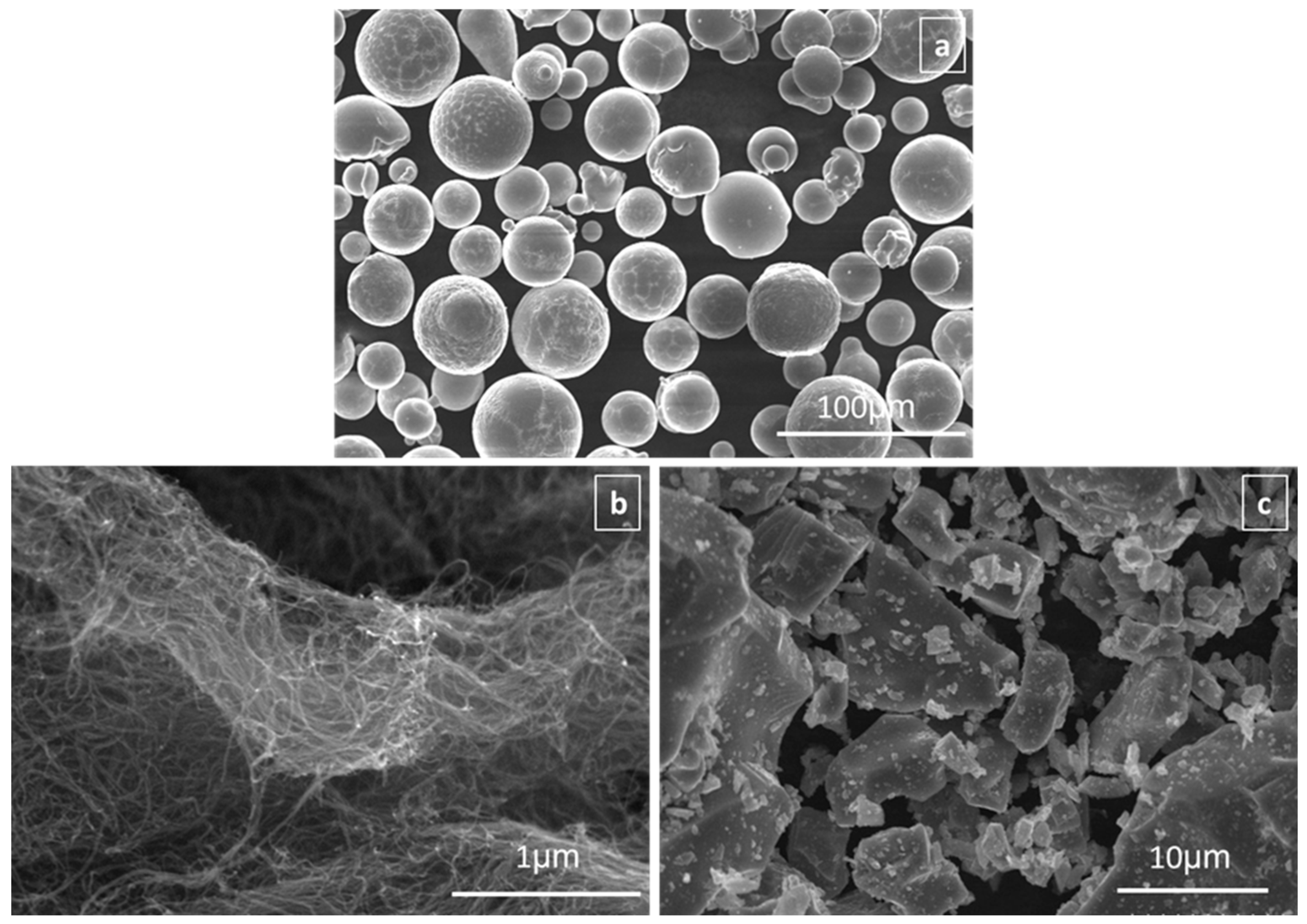
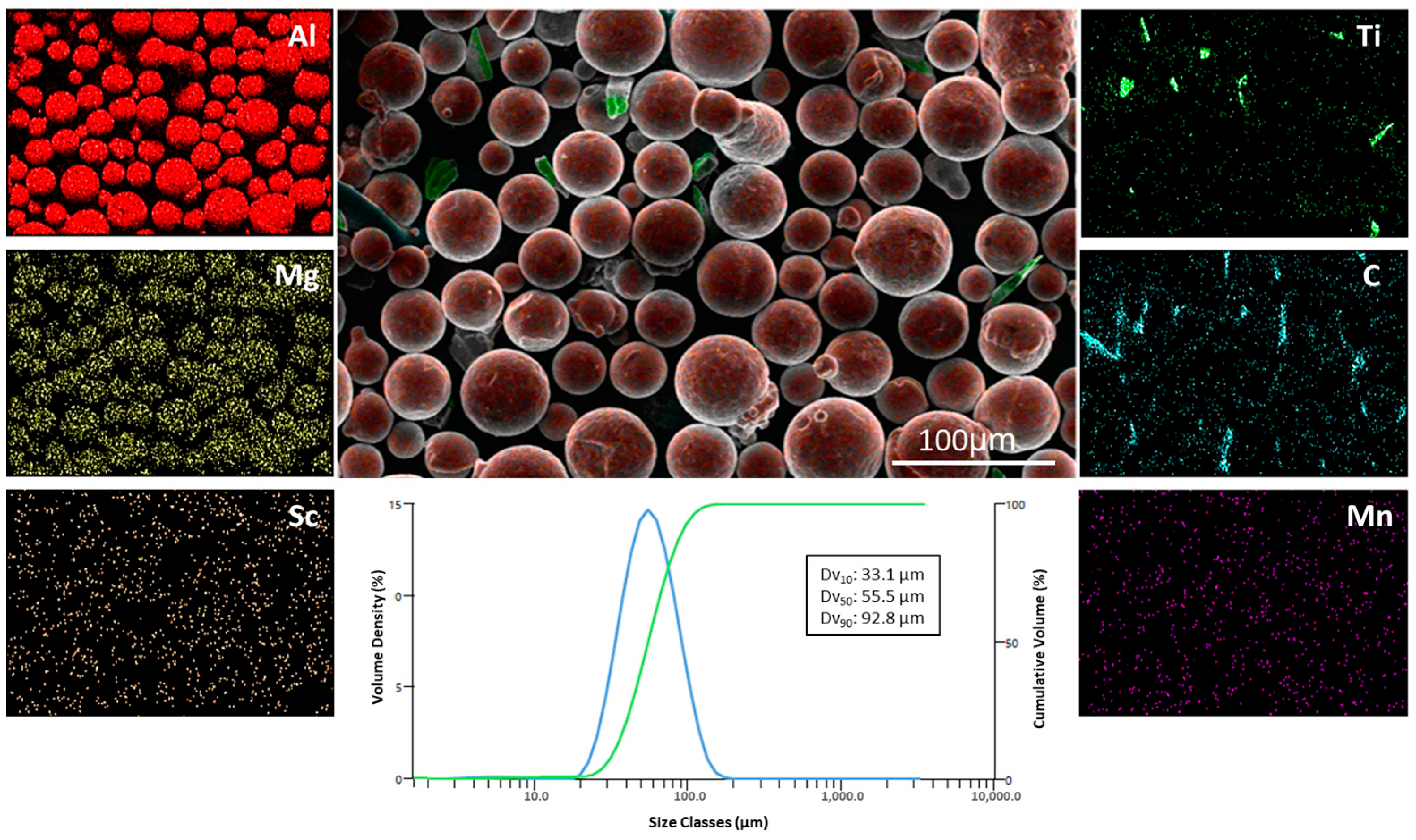
2.1. Preparation of Hybrid Composite Samples

In this study, commercial Scalmalloy® (Toyal Europe) powder based on Al-Mg-Sc-Zr was used as matrix material. The powders have a spherical morphology and a grain size in the range of 15–45 µm. The chemical composition of Scalmalloy® alloy is given in Table 1. Figure 1 shows the initial FE-SEM images of the hybrid composites. As reinforcing phases, TiC (Nanography Nanotechnology™) particles with an average particle size of ~30–40 µm and MWCNT (Nanography Nanotechnology™) particles with a diameter of 20–30 nm and a length of 10–15 µm were used at 5, 10, and 15% by weight. MWCNT reinforcement rates were determined to be 0.8 wt%. Due to the nano-sized structure of the MWCNT powders used, the reinforcement ratio was kept at a low level to ensure optimum mechanical performance, as a high rate of use would increase the risk of agglomeration and inhomogeneous dispersion.
The TiC and MWCNT powders prepared for reinforcement in Scalmalloy® were weighed on a precision balance in the specified ratios. To ensure a homogeneous distribution of the reinforcements in the matrix, a three-dimensional high-energy ball mixer was used. In the mixing process, the powder-to-ball ratio was set as 1:5, and the mixing process was carried out at a speed of 300 rpm (X:500, Y:200) for 4 h. In order to prevent mechanical deformation and deformation of the powders, the mixing process was carried out in a special chamber made of polymer-based kestamite instead of a metal chamber. Thus, possible contamination was prevented, and elements from the chamber wall were prevented from mixing into the composite. The particle size of the sample with 10%TiC + 0.8% MWCNT content from the hybrid composite powder mixtures was measured by the laser diffraction method using a Malvern Mastersizer 3000 (Malvern, Worcestershire, UK) device. The obtained powder mixtures were made into composites by the hot-pressing method. The pressing process was carried out for 60 min in a vacuum atmosphere at a temperature of 560 °C and a constant pressure of 300 MPa using a 40 × 40 mm mold. After pressing, the samples were cooled slowly in a controlled oven environment to minimize residual stresses. The hybrid composite specimens were prepared for transverse rupture stress (TRS) tests, abrasion tests, and microstructure analysis by wire EDM.

2.2. Microstructure Characterization and Phase Analysis

The composite samples were prepared in accordance with standard metallographic procedures prior to microstructure characterization. The samples were sanded with SiC sandpaper with grit numbers 320, 600, 800, and 1200, respectively, and then polished using a 1 µm diamond suspension. After polishing, the samples were etched with Keller’s solution containing 2% HF for 10–15 s to make the microstructures visible.
Microstructural analysis was carried out using a field emission scanning electron microscope (FE-SEM, TESCAN MAIA3 XMU (Tescan, Brno, Czechia)). An acceleration voltage of 5 kV was used in the FE-SEM analysis. Energy-dispersive spectroscopy (EDS) and elemental mapping (MAP) analyses were performed to determine the elemental distribution.
Phase analysis was performed by X-ray diffraction (XRD, Bruker D8 Advance, (Bruker, Karlsruhe, Germany)). The measurements were performed using Cu-Kα radiation (λ = 1.54056 Å) with a 2θ range of 10–90°, a step width of 0.02°, and a scan rate of 0.05 °/s. The obtained diffractometer data were evaluated using X’Pert HighScore Plus (Version: 2.2b PANalytical B.V., (Almelo, The Netherlands)) software for phase identification and peak analysis.

2.3. Density and Microhardness Tests

Density measurements of the produced composite samples were performed according to the Archimedes method according to ASTM B311–17 [37] standards. This method calculated density values by measuring the masses of the samples in both air and a liquid with a known density, specifically pure water. The measurements were performed in a constant temperature-controlled environment at 25 ± 1 °C. Five separate measurements were performed for each sample, and the final density was calculated by averaging the values obtained. Density (ρ) values were determined using Equation (1):
ρ = m m m 1 × ρ w
where m is the mass of the hybrid composite samples in air, m1 is the mass of the samples in pure water, and ρw is the density of pure water. Using Equation (1), the densities of unreinforced Scalmalloy® alloy and hybrid composite samples were determined.
Microhardness measurements were performed using the Vickers method in accordance with ASTM E92-16 [38]. A total of 15 measurements were taken on each specimen at different randomly selected areas on the surface. During the hardness measurements, a 500 gf (gram-force) load was applied to each point, and the load application time was set as 15 s. The results obtained are reported as mean value and standard deviation.

2.4. Transverse Rupture Strength (TRS) Test and Characterization

TRS tests were carried out at room temperature (25 ± 2 °C, 50% relative humidity). The tests were conducted in accordance with the MPIF-10 [39] standard published by the Metal Powder Industries Federation. Three test specimens of 6.45 × 12.7 × 31.2 mm3 were prepared for each composite group. The INSTRON MFL universal testing machine with a maximum capacity of 200 kN was used for the tests. The flexural test was performed in accordance with B528-16 [40] in controlled mode with a loading rate of 1 mm/min. During the test, TRS values for fracture strength were obtained and reported as mean ± standard deviation for each composite type. After the tests, the fracture surfaces of the fractured specimens were examined in detail by field emission scanning electron microscopy (FE-SEM, TESCAN MAIA3 XMU) to determine the fracture mechanisms. With these analyses, crack initiation points, reinforcement phase distribution, and fracture surface morphologies were evaluated, and fracture behavior was interpreted. In addition, standard deviation values in the TRS tests were calculated as percentages.

2.5. Tribological Behaviors and Characterization

The wear tests were performed under dry conditions at room temperature (25 ± 2 °C, 50% relative humidity) using an Anton Paar TRB3 model reciprocating wear tester. The constant load applied in the tests was 5 N, the total sliding distance was 100 m, the stroke length was 5 mm, and the test frequency was 2 Hz. A zirconia (ZrO2) ball with a diameter of 6 mm and a hardness of approximately 1200 HV was used as the counter material. All tests were conducted in accordance with ASTM G133-05 [41]. According to the wear test results, the specific wear rate (ω) of each sample was calculated using Equation (2):
ω = Δ V L × N
where ΔV is the wear volume, L is the sliding distance, and N is the applied load. Volumetric wear was calculated by considering the measured mass loss and the experimental densities of the samples. Specific wear rate values are expressed in mm3/N.m. All samples were evaluated under the same test parameters, and comparative analysis was performed.
After wear tests, the worn surfaces were microstructurally examined by field emission scanning electron microscopy (FE-SEM, TESCAN MAIA3 XMU) and the wear mechanisms were analyzed in detail.

3. Results and Discussion

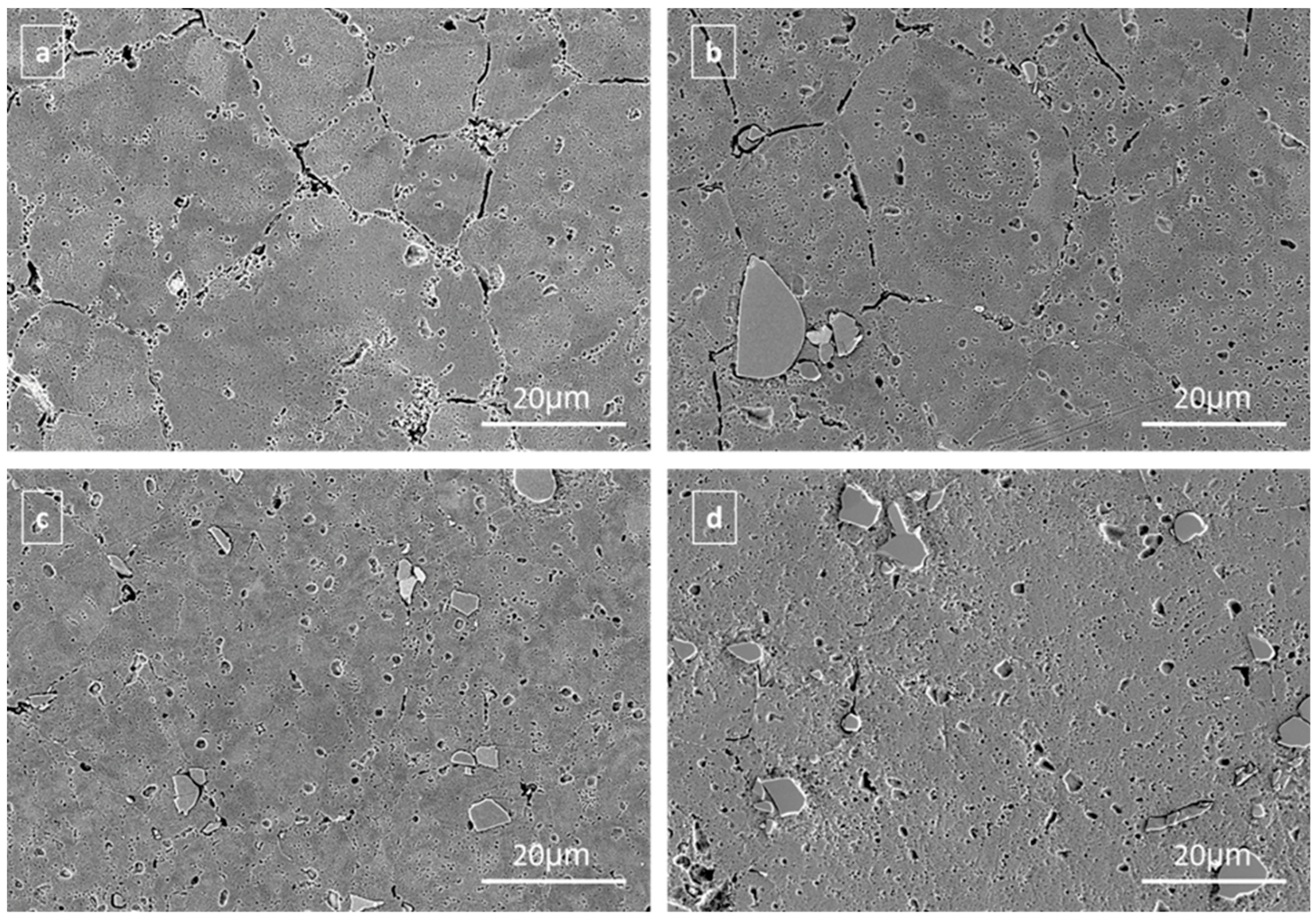
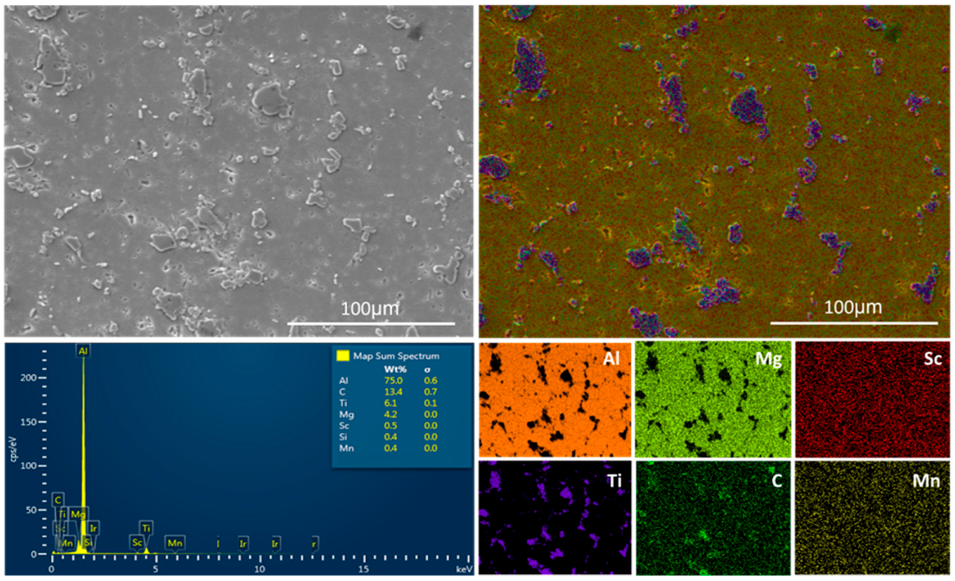
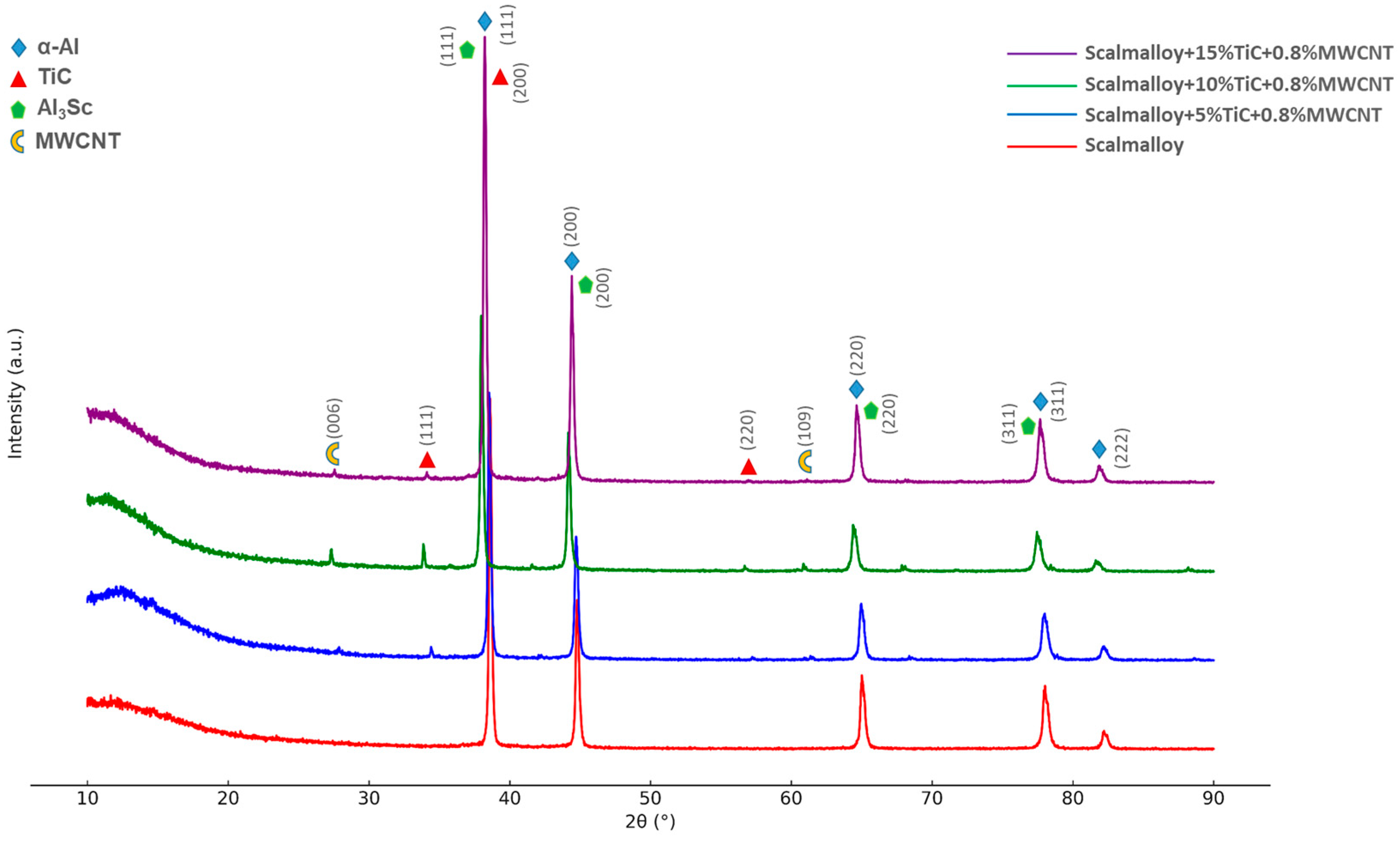
3.1. Microstructure Characterization

Figure 2 shows the initial powder morphology and elemental distribution maps of the Scalmalloy® +10%TiC + 0.8%MWCNT hybrid composite sample obtained using a three-dimensional high-energy ball mixer. The mixing process was carried out in a polymer-based Kestamite chamber to preserve the structural integrity of the powders and prevent contamination. Thus, unwanted elemental inputs from the metal-based vessels were avoided. SEM analysis after the grinding process shows that the powder particles largely retain their spherical morphology and that their surface roughness remains at a low level. This situation reveals that the high-energy mixing process is aimed at providing homogeneous distribution rather than structural deformation and that the mechanical alloying effect is limited. This stability in morphology facilitates the proper stacking of particles during sintering and contributes to the increase in density. SEM analysis indicates that the powders have spherical morphology and low surface roughness, which contributes to the density increase during pressing and sintering processes. EDS map analysis shows that the Al-based Scalmalloy® matrix and the elements Mg, Mn, Zr, and Sc are homogeneously distributed in the matrix. This homogeneous distribution supports the microstructural integrity of the matrix. The Ti elemental map reveals that, although TiC particles show local concentrations within the matrix phase, the overall distribution is quite successful. The carbon elemental map clearly shows that MWCNTs are homogeneously distributed in the powder matrix without agglomeration. This homogeneous dispersion is critical for improving load transfer, arresting crack propagation, and enhancing mechanical performance in hybrid composite systems. In conclusion, the obtained EDS maps and SEM images show that the high-energy mixing method applied makes significant contributions to the homogeneous dispersion of powders and the microstructural optimization of hybrid composites.
Figure 3 shows FE-SEM microstructure images of unreinforced Scalmalloy® and hybrid composite specimens containing different ratios of TiC + MWCNT reinforcement produced by the hot-pressing method. In Figure 3a, it is observed that the unreinforced Scalmalloy® sample has a homogeneous grain structure and limited microvoids due to the effect of the manufacturing method. The existing voids are due to the limited diffusion effect during pressing and do not seriously affect the overall structural integrity. In the Scalmalloy® + 5%TiC + 0.8%MWCNT hybrid composite sample in Figure 3b, it is seen that TiC and MWCNT reinforcements are homogeneously distributed throughout the matrix and the grain sizes remain stable due to the effect of the reinforcement phases. The reinforcement particles contributed to the control of growth at the grain boundaries. In the Scalmalloy® + 10%TiC + 0.8%MWCNT sample presented in Figure 3c, it was found that the particle density in the matrix increased due to the increase in the amount of TiC particles, but the particles maintained their homogeneous distribution. This shows that appropriate mixing and pressing parameters allow us to obtain a homogeneous microstructure even when the reinforcement ratio is increased. In the Scalmalloy® + 15%TiC + 0.8%MWCNT sample shown in Figure 3d, a significant increase in TiC particle density was observed. The increased particle ratio increases the surface area between the matrix phase and the reinforcement phase, thus providing a favorable microstructural basis for potential mechanical strength enhancement. The microstructures obtained were generally homogeneous and composed of equiaxed grains, and a stable matrix structure was obtained via hot pressing. In the literature, oriented and columnar grain growth is often reported in Scalmalloy® alloys produced using additive manufacturing methods. Mohebbi et al. [7], in their study on Al-Mg-Sc-Zr alloy using the Powder-Bed Fusion process, reported effective nucleation at the fusion boundary in the melt pool and the formation of fine equiaxed grains in the microstructure, but the presence of coarse and columnar grains due to insufficient nucleation in the core region. Similarly, Wang et al. [42] reported in their study the epitaxial growth of columnar grains in Al-Mg-Sc-Zr alloy produced by the L-PBF method. Thanks to the hot-pressing method applied in this study, the columnar growth tendencies often observed in additive manufacturing processes were eliminated, and a microstructure with more homogeneous, equiaxed, and isotropic mechanical properties was obtained.
Figure 4 displays the microstructural characterization, SEM, and EDS-MAP analysis of the hybrid composite obtained with 10% TiC and 0.8% MWCNT reinforcement in a Scalmalloy® matrix. Additionally, Table 2 presents the chemical composition results of the general EDS analysis for this hybrid composite.
SEM images reveal that the reinforcement phases are homogeneously dispersed in the matrix and show no signs of agglomeration. This homogeneous distribution plays an important role in improving the mechanical properties of the composite. EDS analysis indicates that the matrix elements Al, Mg, Mn, and Sc are homogeneously distributed throughout the composite. The homogeneous distribution of Sc and Mn in particular shows that Scalmalloy® retains its characteristic microstructural stability and that the reinforcement phases do not disturb this stability. The intensity of Ti and C elements observed in the EDS maps shows that TiC particles are uniformly distributed in the matrix, and MWCNTs together with C signals form a good bond between the matrix-reinforcement particles. These microstructural findings are in agreement with the results reported in the literature for similar hybrid composite systems. For example, Chandrakanth et al. [43] created hybrid composite samples using TiC and graphite reinforcements in a copper matrix through a microwave process. They found that TiC and graphite reinforcements are homogeneously distributed in the matrix phase and have isotropic mechanical properties and uniform stress distribution in the structure during service. In another study, Nyanor et al. [44] produced hybrid composite materials by reinforcing an Al matrix with CNT and TiC. The authors stated in their study that the short milling times used preserved the structural integrity and homogeneity of CNT and TiC reinforcement.
Figure 5 shows the XRD patterns of the unmodified Scalmalloy® alloy and hybrid composites produced with increasing MWCNTs (0.4%, 0.8%, and 1.2%) at a constant TiC content of 5%. In all samples, the characteristic peaks corresponding to the (111), (200), (220), (311), and (222) planes of the α-Al phase, the primary phase, were detected with high intensity and sharpness (PDF 01-085-1327). This indicates that the Al matrix of the Scalmalloy® alloy has retained its crystalline structure. The Sc element in the alloy combines with the Al element, which is the main part, to create the Al3Sc precipitation phase (PDF 00-017-0412), especially in the reinforced hybrid composite samples. In reinforced Scalmalloy® hybrid composites, the primary cause of the increased peak intensity of Al3Sc precipitation phases is believed to stem from TiC and MWCNT reinforcements forming heterogeneous nucleation centers within the matrix phase, thereby accelerating the precipitation kinetics [45]. These particles, along with increased dislocation density, facilitate the precipitation of Sc atoms within the Al lattice structure forming the main phase, thereby promoting the distinct formation of the Al3Sc phase. In a study by Noventy and Ardell, it was noted that Al3Sc precipitates in dislocation regions are influenced by particle–matrix interactions [46]. In another study, Kuo et al. investigated the effect of Al3Sc precipitates on mechanical properties in Scalmalloy® samples produced by additive manufacturing and reported that homogeneously distributed precipitates enhance mechanical strength [47]. The (110), (111), and (220) planes of the TiC phase identified in hybrid composite samples (PDF 01-074-1219) indicate that the particles remain in a crystalline structure within the structure without degradation during hot pressing. MWCNT was used as a reinforcement phase, and although at low intensity, characteristic reflections were observed in the XRD pattern of hybrid composite samples. MWCNTs with a hexagonal crystal structure produced signals corresponding to (006) and (109) planes, and these reflections were evaluated in accordance with the references mentioned in the literature (PDF 00-026-1076). However, the reflections of MWCNT generally appear as weak intensity and indistinct peaks due to the low amount of carbon nanotubes, their nanometric dimensions, and graphitic structures that cause low X-ray scattering, as frequently reported in the literature [48,49].

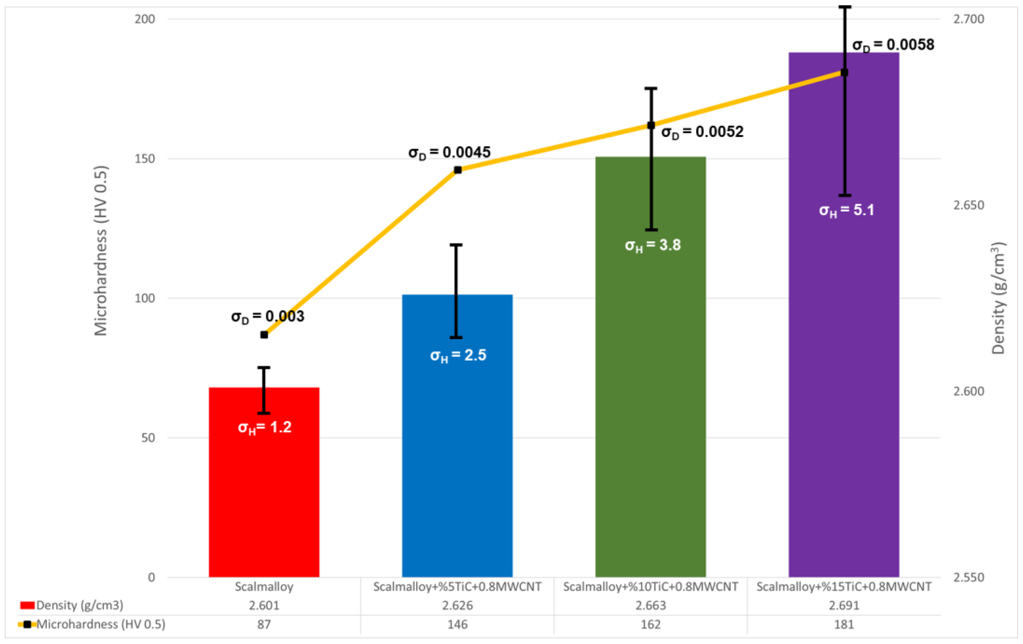
3.2. Density and Hardness Tests

Figure 6 shows the microhardness (HV 0.5) and density values of unreinforced Scalmalloy® and hybrid composites reinforced with 5%, 10%, and 15% TiC + 0.8% MWCNT. Also, in the figure, σH represents the standard deviation values obtained from microhardness measurements, while σD represents those obtained from density measurements. The structural and mechanical effects of the reinforcements were compared using the unreinforced Scalmalloy® sample with a hardness of 87 HV and a density of 2.601 g/cm3 as a reference. When the microhardness values were examined, the hardness increased by 67.8% to 146 HV with 5% TiC + 0.8% MWCNT reinforcement. This increase can be explained by the high hardness of TiC, together with the high elastic modulus and nanoscale effective load-bearing properties of MWCNTs. With 10% TiC reinforcement, the hardness value increased to 162 HV, which is an 86.2% increase compared to the unreinforced structure. The highest hardness was measured at 181 HV in the composite containing 15% TiC, representing a total increase of 108.0% compared to the initial value. This can be explained by the more dense, homogeneous, and more effective distribution of the reinforcement phases in the matrix. In particular, the effective distribution of TiC particles at the grain boundaries and throughout the matrix limits plastic deformation by preventing dislocation movements, resulting in a harder structure. In terms of density values, a more limited increase trend was observed compared to hardness. While the density of unreinforced Scalmalloy® was 2.601 g/cm3, this value was recorded as 2.626 g/cm3 in the composite containing 5% TiC, representing an increase of 0.96%. With 10% TiC reinforcement, the density reached 2.663 g/cm3 (a 2.38% increase), and with 15% TiC, it reached 2.691 g/cm3 (a 3.46% increase). Since the density of TiC particles (4.93 g/cm3) is quite high compared to the Scalmalloy matrix, it is expected that the increasing amount of reinforcement will theoretically contribute to the increase in density. However, the low density of MWCNTs (~2.0 g/cm3) and micro-pores that may arise during the incorporation of reinforcement phases into the microstructure partially limit this increase. This parallel increase in hardness and density is directly related to the more compact structure after sintering and the strengthening of the reinforcement–matrix interface. Hybrid reinforcements have increased the hardness within the matrix and positively affected the sintering efficiency, facilitating the reduction in micro-pores. In this context, parallel findings reported in the literature have been observed. Nayim et al. [50] reported in their study that they reinforced the Aluminium 3003 matrix with CNT and TiC reinforcements in a hybrid manner and observed an increase in hardness values with increasing reinforcement. With an increasing reinforcement ratio, a certain increase was observed in the standard deviation values obtained from microhardness tests. This situation can be explained by the fact that, although TiC and MWCNT reinforcement phases are homogeneously distributed within the matrix phase, different hardness values occur in the regions that directly contact the reinforcement particles and those that do not in the measurements performed at the microscale. Since the measuring tip encounters higher resistance in the regions where the hard phases are located, SD values naturally increase. On the other hand, the standard deviations of the density values are quite low. This result shows that porosity is effectively reduced under high pressure and temperature applied by the hot-pressing method and the density is provided with high consistency in each sample. In addition, it is understood that the reinforcement phases used are well integrated into the matrix during the sintering process and do not negatively affect the volumetric density.

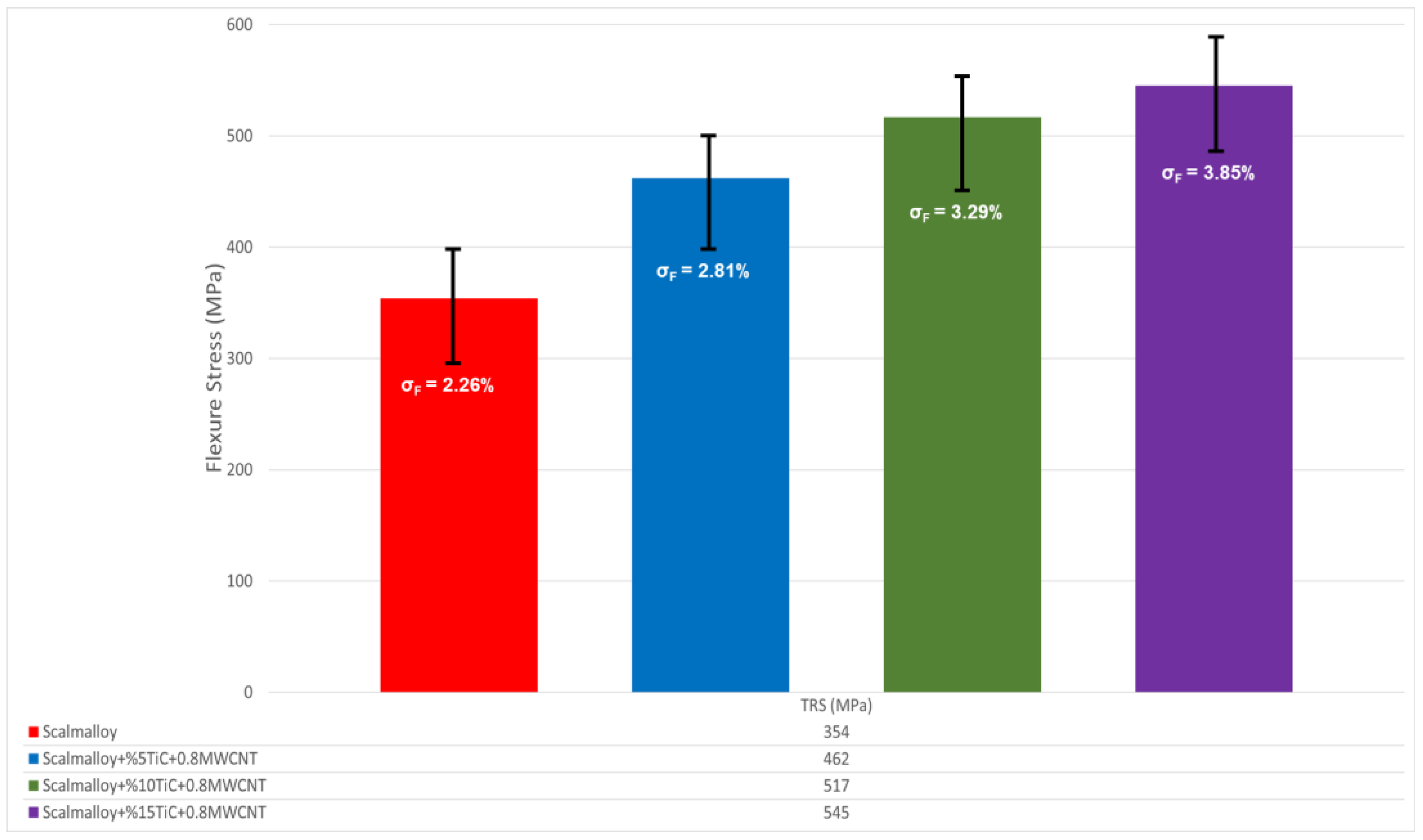
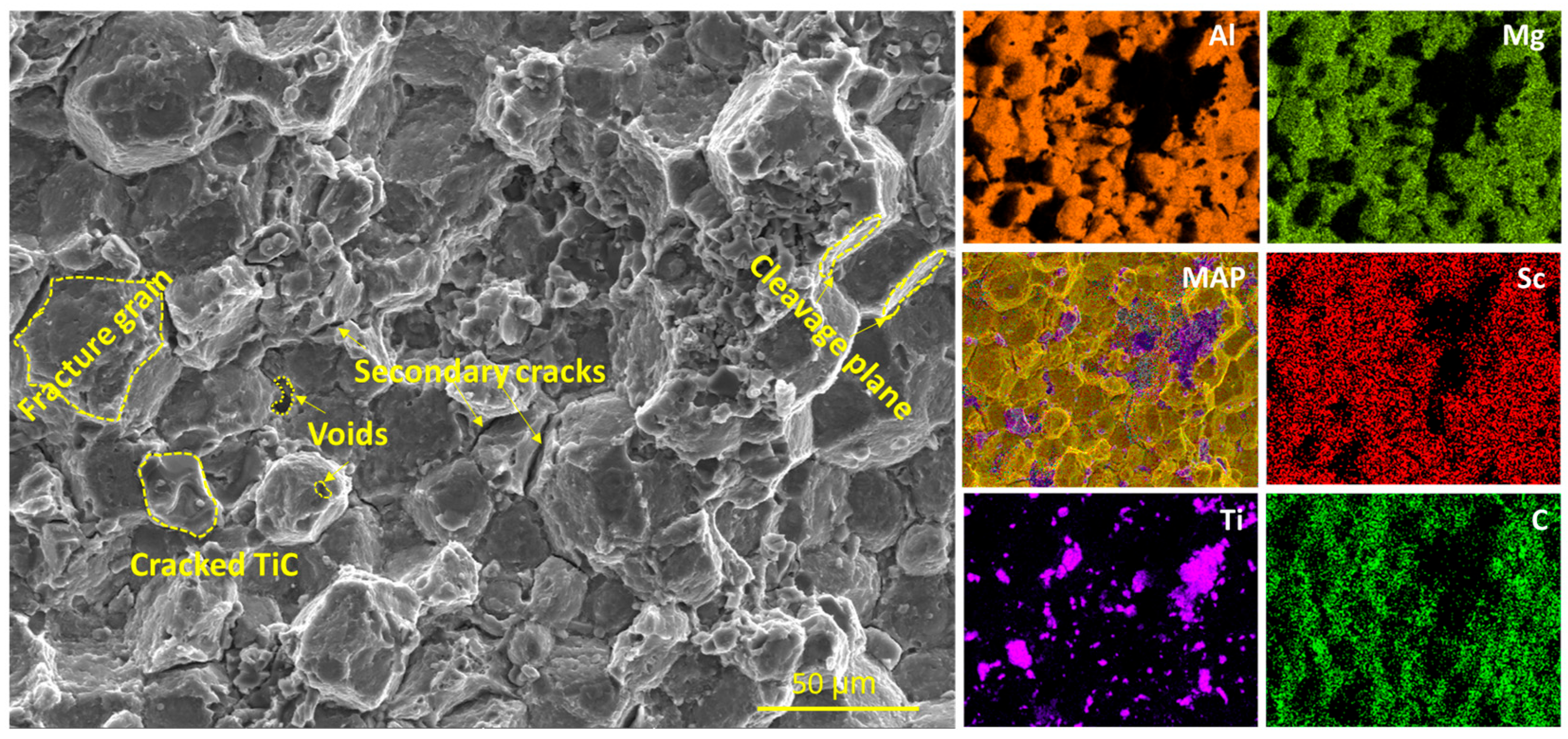
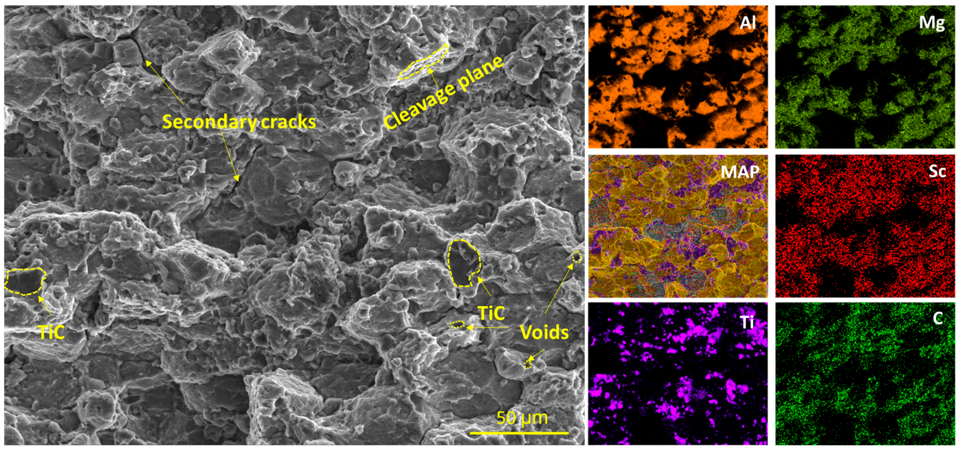
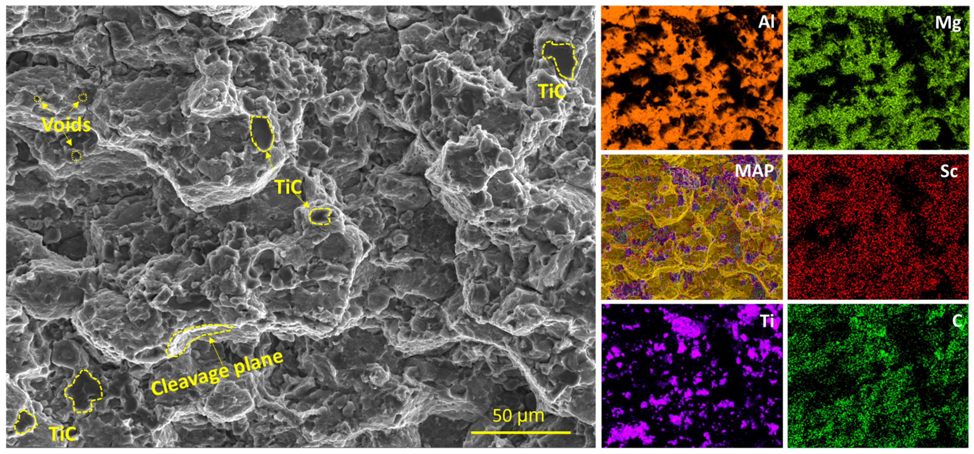
3.3. TRS Testing and Fractured Surface Analysis

The TRS results shown in Figure 7 demonstrate the mechanical performance of hybrid composites with a fixed MWCNT content of 0.8% in addition to TiC reinforcement at 5%, 10%, and 15% by weight in the Scalmalloy® matrix. While the unreinforced Scalmalloy® sample exhibited a TRS value of 354 MPa, this value increased to 462 MPa in the 5% TiC + 0.8% MWCNT-reinforced composite, corresponding to a 30.5% improvement. When the reinforcement ratio was increased to 10%, the TRS value reached 517 MPa, an increase of 46% compared to the unreinforced sample. The highest TRS resistance was measured as 545 MPa in the hybrid composite containing 15% TiC, which is a 54% increase compared to the unreinforced sample. Despite these increases, the data obtained also show that the hybrid reinforcement system causes a decrease in ductile deformation capacity. The evaluation of TRS and hardness values together reveals that the material evolves into a more rigid and brittle structure as the reinforcement ratio increases. This situation can be explained by the fact that the high-hardness TiC and MWCNT phases limit dislocation movements and terminate crack propagation with more sudden fractures. In structural applications, this balance between increased strength and decreased ductility should be considered. One of the main reasons for this increase is the micro-reinforcement effect of TiC particles and MWCNTs homogeneously distributed in the matrix. TiCs, which are hard ceramic particles, can prevent crack propagation by forming effective barriers, causing cracks to change direction or terminate under load. In addition, microstructural stress fields formed around the reinforcement particles suppress crack growth by changing the stress distribution at the crack tips [51]. MWCNTs, with their high elastic modulus and tensile strength, support load transfer at the matrix reinforcement interface and prevent the propagation of micro cracks. In particular, this hybrid reinforcement system positively affects fracture resistance by absorbing stress accumulations around micro-pores, which are critical for structures produced by powder metallurgy. The progression of cracks formed under bending load also provides information about the ductility and brittleness behavior of the material. It is understood that with an increasing reinforcement ratio, hybrid composites cause a decrease in ductile deformation capacity due to increased stiffness, and the structure shifts towards brittleness. In addition, a direct correlation is observed between the TRS results and the stiffness values obtained in the previous section. As the reinforcement ratio increased, significant increases in hardness values occurred (e.g., from 87 HV to 181 HV), which showed an increase parallel to the bending strength. The limitation of dislocation movements of the hard phases, the strengthening of the load transfer mechanism, and the emergence of a more rigid structure at the micro scale are among the main reasons for this parallel increase [52]. SD values (σF) increased from 2.26% in the unreinforced sample to 3.85% in the 15% TiC-reinforced sample in TRS measurements. This increase is thought to be due to the increase in microstructural diversity depending on the number of reinforcement phases in the composite structure and local stress distribution differences between samples. Nevertheless, the low SD percentages obtained in all groups show that the structural integrity of the samples produced by hot pressing is high and statistically reliable results were obtained.
Figure 8 shows the microstructural properties of the fracture surface of the unreinforced Scalmalloy® alloy after the TRS test, obtained by FE-SEM and EDS-MAP analyses, and the fracture mechanism. The image shows clearly defined, large, and distinctly separated grain structures. This indicates that the fractures caused by deformation primarily occur along grain boundaries. During fracture, it is understood that load transfer is highly concentrated in the direction of grain boundaries, and fracture develops along these discontinuities. The elongated dimples observed in the SEM image clearly indicate that the ductile fracture is dominant. The fact that these dimples extend particularly along grain boundaries supports the notion that fractures occur through a ductile and grain boundary-controlled mechanism. In this specimen, the depth and width of the dimples indicate a high plastic deformation capacity, while the limited and oriented structure of the dimple density suggests that the fracture initiates and progresses along grain boundaries. Numerous fine, oriented cracks, defined as secondary cracks, were also observed on the fracture surface. These cracks indicate that micro cracks propagating within the matrix during bending loading eventually coalesced to initiate a fracture and ultimately formed the main fracture plane. Secondary cracks primarily occur in brittle grain boundaries or regions with low toughness. In this context, it has been reported in the literature that the Al3Sc dispersions present in Scalmalloy® act as a barrier against dislocation movement, thereby enhancing strength but simultaneously localizing deformation and predisposing the material to brittle behavior [9]. EDS-MAP analyses revealed that Al, Mg, Sc, and Mn elements are homogeneously distributed along the fracture surface. The elemental distribution suggests that no phase separation, elemental segregation, or precipitation occurred in the alloy structure during the TRS test loading. The unreinforced Scalmalloy® alloy exhibited a surface morphology with high plasticity and ductile fracture characteristics after the TRS test.
Figure 9 shows the surface and elemental characteristics of a hybrid Scalmalloy® composite sample with 5% TiC and 0.8% MWCNT after the TRS test, analyzed using SEM and EDS-MAP. The distinct microstructural features visible in the image include cleavage planes, cracked TiC particles, voids, secondary cracks, and grain structures, as well as the effects of reinforcement phase fractures on the overall fracture characteristics. The general appearance of the fracture surface and dimensionless structure ratios indicate a more complex fracture range. The TRS test subjected the specimen to both tensile and bending stresses, utilizing three-point bending loading [53]. At this length, the cracks seen on the surface show signs of a brittle fracture, and the highest tensile stresses build up, particularly on the bottom surface. This fracture usually occurs in the assembly where the plastic deformation capacity of the matrix is locally limited. It is observed that the MWCNT dispersion interacts with TiC, slows down the movement of dislocations, and causes the fracture to change from being ductile to brittle. The cracked TiC diseases in the SEM image show that these ceramic phases can break despite their high rigidity during load transfer. In this case, the TiC contributes to the cracks by cracking at the critical propagation limit of the load-carrying capacity, and the contribution of the reinforcement phases to the strength increase is also revealed. The fractured grain structures and the fracture-aligned void formations along them represent a process that is marked and progresses with the formation of the classical ductile fracture. However, the fact that these boundaries are limited and that they are observed together with the cracks reveals a transitional mechanism where ductile and fracture properties take place simultaneously [54]. In the EDS-MAP maps, it is seen that Ti and C elements, i.e., reinforcement phases, are concentrated and that there is information at certain intervals along the fractures. This location directs the crack propagation together with the increase in the strength of the effective barriers against dislocation movement. MAP analyses show that TiC phases are not only effective in the rigid reinforcement contribution but also in controlling the fracture direction. The homogeneous distribution of matrix elements such as Al and Mg shows that microstructural deteriorations such as dissociation, dissolution, or phase separation did not occur during the test and that the matrix maintained its structural stability. Similarly, Sc and Mn elements were distributed in a shaped form in all parts. This situation is an indication that the stable precipitation of Scalmalloy® alloy was also preserved during the TRS test. As a result, the multiple fracture modes observed on the fracture surface formed after the TRS test in the hybrid composite sample containing 5%TiC + 0.8% MWCNT stability show that the reinforcement phases direct the fracture by causing both mechanical resistance and local stress concentrations. While this structure provides positive contributions in terms of strength increase, it increases the increase in microstructural fracture analysis by making the fracture morphology more complex.
Figure 10 shows the SEM and EDS-MAP analyses of the fracture surface of the Scalmalloy® hybrid composite sample with 10% TiC and 0.8% MWCNT reinforcement after the TRS test. The surface morphology causes a more pronounced brittle fracture behavior compared to the previous samples, and the cleavage planes, voids, secondary cracks, and cracked TiC particles observed along the fracture reveal that the microstructural fracture mechanisms are multidimensional. In the fracture surface formed as a result of the three-point bending loading applied in the TRS test, brittle cleavage planes and notched crack tips were clearly detected. This situation is attributed to both the limitation of the deformation capacity of the matrix and the crack-initiator role of the reinforcement phases by causing local stress accumulations [55]. The fact that TiC particles are observed more commonly with a high volume fraction indicates that the regions showing microstructural resistance under load increase and the load transfer capacity expands. However, this resistance also led to localized deformation in certain regions and accelerated fracture development. The homogeneous distribution of Ti and C elements throughout the microstructure in EDS-MAP maps confirms that the TiC reinforcement phases are actively involved not only in the grain boundaries but also in the intra-grain regions. This regular distribution causes the dislocation movement to be spread over the entire volume and to be blocked to a higher extent, which increases the TRS mechanical strength value by approximately 46% compared to the unreinforced structure. However, formations such as microscopic voids and secondary cracks indicate that the ductile deformation is concentrated in limited regions and that a transitional mechanism dominates the fracture process. The cracked TiC structures observed in the SEM image show that these particles undergo local fractures during the TRS test despite their high elastic moduli. These particles crack in the regions where the stress intensity is focused and cause interface separation with the surrounding matrix, which accelerates the crack formations that begin with interfacial debonding [56]. In addition, these broken particles cause the crack tips to deviate, causing the fracture surface to gain a rougher and non-directional morphology. It was observed that Al, Mg, Sc, and Mn elements were distributed homogeneously throughout the surface in the MAP maps.
Figure 11 presents high-resolution SEM and EDS-MAP analyses of the fracture surface of the Scalmalloy® hybrid composite sample containing 15% TiC and 0.8% MWCNT reinforcement after the TRS test. The cleavage planes, voids, and TiC particles embedded in the matrix, which are noticeable in the image, indicate that the fracture has acquired a completely brittle character and that the microstructural deformation mechanisms are largely limited. The increasing ratio of reinforcement phases has significantly reduced the deformation capacity by suppressing the movement of dislocations both within the grain and along the grain boundary. The crack initiation points formed around the TiC particles and the cleavage planes concentrated around these particles reveal that although the load transfer is effective, local stress concentrations create serious fracture risks. This means that although the composite structure gains superiority in terms of strength, its ductile deformation capacity has been significantly weakened. In fact, despite reaching the highest TRS value in this sample, the fracture surface morphology does not show traces of ductile deformation. The load transfer efficiency between the matrix and the reinforcement increased due to the high elastic modulus of MWCNTs, and this additive combined with the TiC particles to form a dual reinforcement effect. However, this situation prevented the plastic deformation rather than supporting it, which caused the stress accumulations to concentrate at a single point and trigger sudden crack formations [57]. The cleavage planes seen in the SEM image progressed together with the local deformation weaknesses around the TiC, causing the surface to gain a completely brittle fracture character. EDS-MAP analyses show that the distribution of Ti and C elements is quite homogeneous, but this distribution has an effect that limits plasticity while providing structural integrity. The regular distribution of alloy elements such as Al, Mg, and Sc reveals that the matrix can maintain its chemical integrity even under TRS loading. The high reinforcement ratio caused the fracture to change from ductile to completely brittle. The dips around the TiC and the random direction of the cracks show that the fracture spreads unevenly and the ability of the matrix to absorb energy goes down.

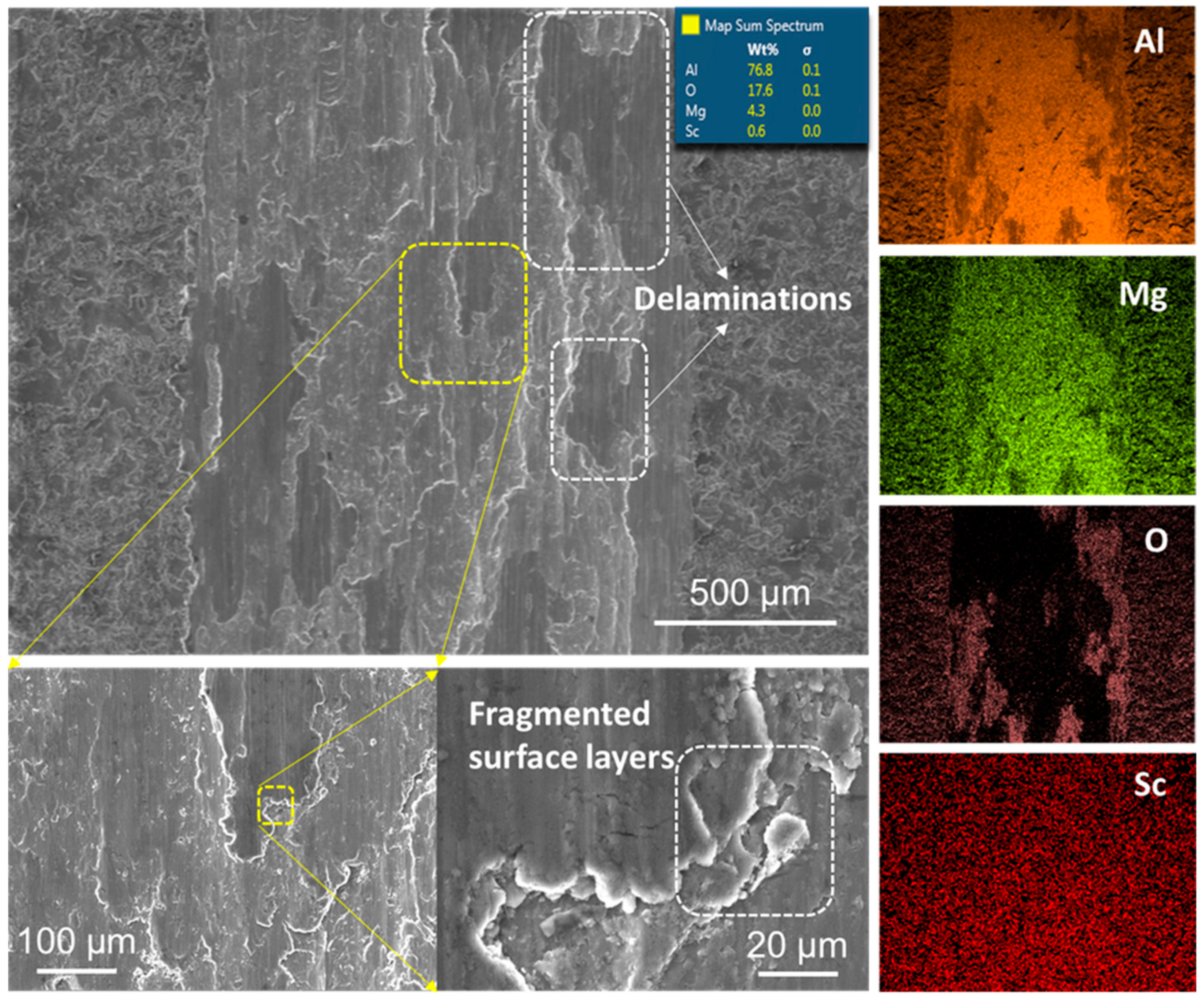
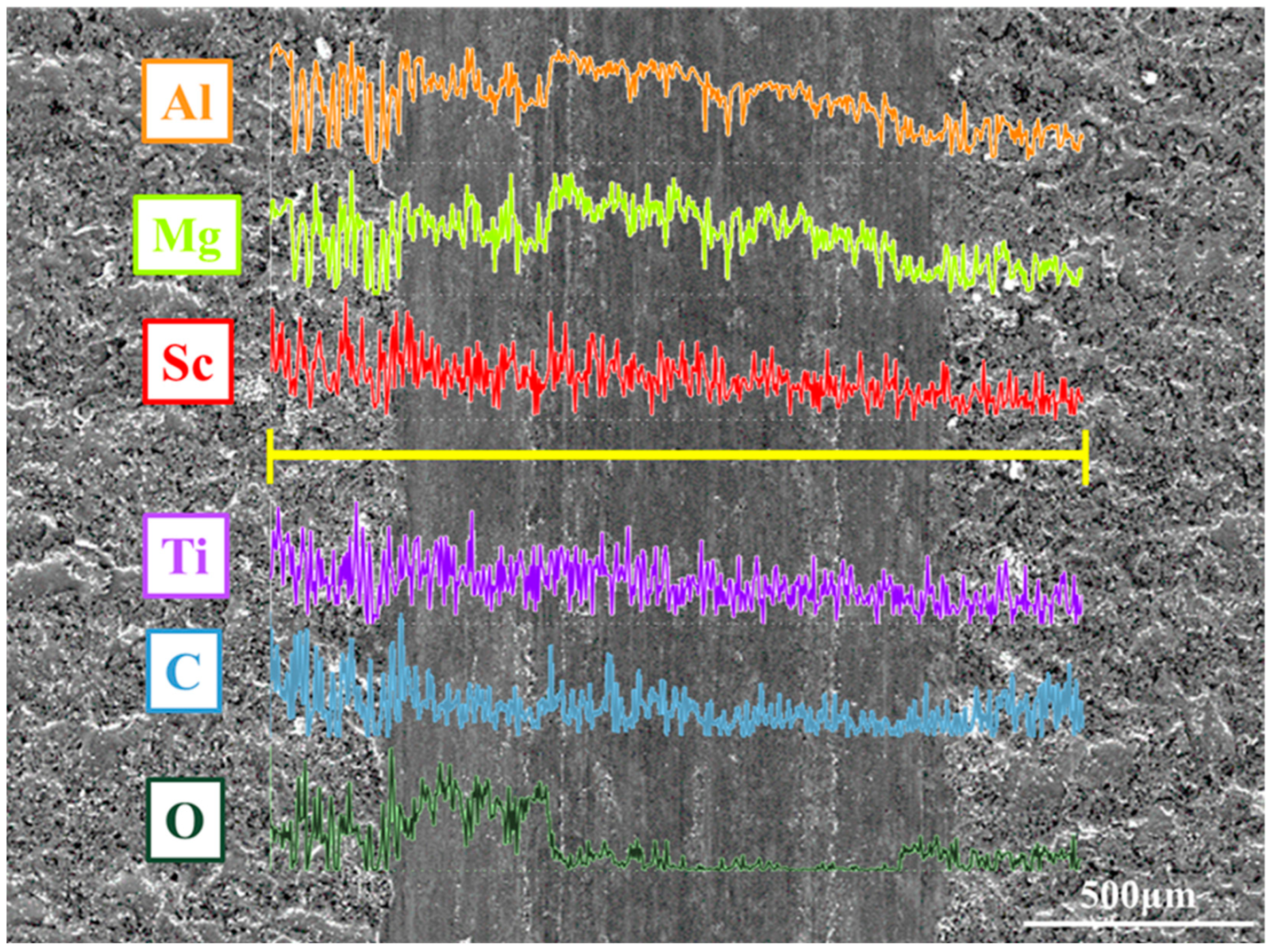
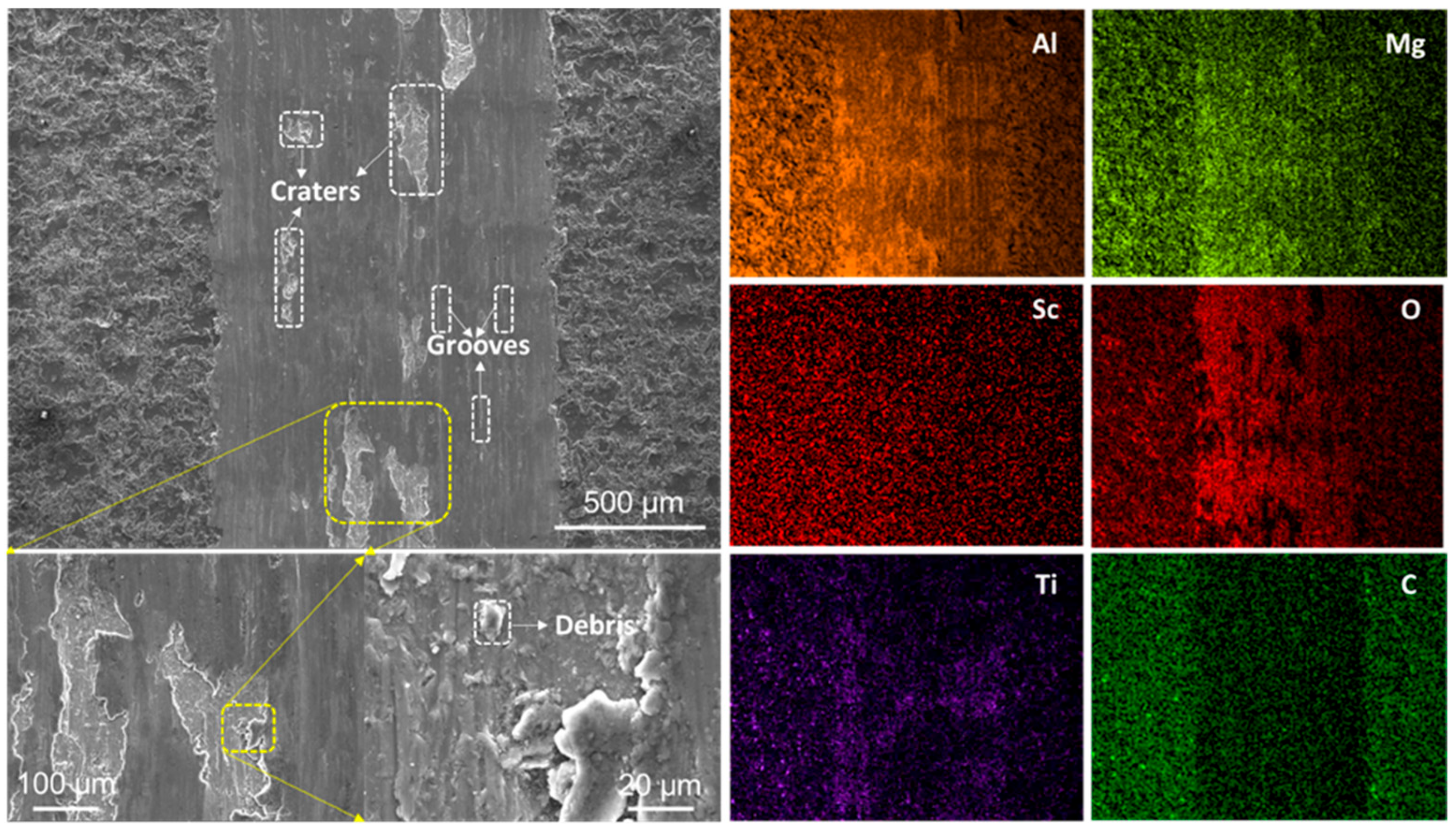
3.4. Wear Testing and Worn Surface Examination

Figure 12 presents the coefficient of friction (CoF)–distance curves, illustrating how an increased TiC reinforcement ratio affects the tribological behavior of hybrid Scalmalloy® composites. The unreinforced Scalmalloy® sample exhibited the highest friction coefficient, with an average of µ: 0.521 throughout the test, indicating that the lower hardness value of the matrix creates a larger contact area with the opposing surface and that the adhesion-dominated wear mechanism is dominant. The friction coefficient decreased to µ: 0.502 with 5% TiC reinforcement, indicating that the surface deformation was limited with the increase in matrix hardness and the microstructural contact was less adhesive. This trend continued in the 10% TiC-reinforced composite, reaching a value of µ: 0.491. In this sample, it is thought that the load transfer at the matrix–reinforcement interface became more efficient and the thermomechanical stability increased due to the high elasticity modulus of MWCNTs. Samal et al., in their study, reinforced the A383 alloy with B4C and MWCNT reinforcements at different rates. They reported that hybrid metal matrix composites had a positive effect on tribological properties compared to unreinforced alloys [58]. The lowest average friction coefficient µ: 0.475 belongs to the sample containing 15% TiC. This situation shows that high-rate TiC ceramics minimize plastic flow and adhesion in surface contact areas, resulting in lower friction energy during sliding. However, a short-term fluctuation was observed in this sample at the beginning of the test. This situation is thought to be due to a temporary imbalance in the system at the first moments of contact between the matrix-reinforcement elements in the surface microstructure.
Figure 13 shows the specific wear rate values of the hybrid composites containing 5%, 10%, and 15% TiC and a constant 0.8% MWCNT with unreinforced Scalmalloy® in comparison. The unreinforced Scalmalloy® sample exhibited a high wear rate of 9.70 × 10⁻² mm3/N m, which was associated with the low hardness and poor surface resistance properties of the structure. With 5% TiC + 0.8MWCNT reinforcement, this rate decreased to 8.10 × 10⁻³ mm3/N.m, providing an improvement of approximately 91.6%. With 10% TiC reinforcement, a value of 3.40 × 10⁻³ mm3/N.m was reached, providing an improvement of 96.5% compared to the unreinforced sample. The lowest wear rate was observed in the %15TiC + 0.8MWCNT composite, and the value was recorded as 1.26 × 10⁻³ mm3/N.m in this sample, which corresponds to an improvement of approximately 98.7%.
This decrease in wear rate is directly related to the increased hardness of the composites. TiC and MWCNT reinforcements acted as effective barrier phases, restricting dislocation movements within the matrix, which minimized surface deformation and significantly increased wear resistance. Especially thanks to the ceramic structure of TiC and the high elastic modulus of MWCNTs, stress accumulation in the matrix was effectively distributed, and surface damages caused by plastic deformation were largely prevented. Thus, with the increasing reinforcement rate, material loss from the surface was significantly reduced, and wear performance was improved thanks to the higher microhardness and limited dislocation activity.
Figure 14 shows the SEM, EDS, and MAP analyses of unreinforced Scalmalloy® and the surface topography and elemental distribution after wear under dry sliding conditions. The most important findings that draw attention to the surface morphology are dense delamination traces, fragmented surface layers, and high deformation zones. In particular, the wear trace is clearly wide, which reveals that the adhesive wear mechanism is dominant in this material. During wear, the surface particles adhering to the opposite surface broke off with successive loadings and caused volumetric losses on the surface; this increased the trace width. In the SEM image, the areas extending parallel to the surface and occasionally limited by microstructural separations present microscopic traces of delamination. These structures, which occur due to excessive local plasticity, represent layers separated from the surface under high stress [59]. In addition, it is seen that the matrix structure is more easily deformed under friction loads due to low hardness and strength properties and cannot show sufficient resistance against wear. EDS and MAP analyses show that Al, Mg, and Sc elements exhibit a homogeneous distribution throughout the surface; this situation reveals that chemical segregation, phase separation, or oxidation-related deterioration does not occur at a significant level during the wear process. However, the O element was detected densely on the surface. This finding shows that oxidation has started on the surface, and the heat generated during friction prepares the ground for local oxide film formation.
Figure 15 shows the SEM and EDS-MAP analyses of the Scalmalloy® hybrid composite sample containing 5% TiC + 0.8% MWCNT reinforcement under dry sliding conditions, the surface damage it is exposed to, and the elemental distribution properties in detail. The results clearly show that this reinforcement composition contributes positively to the tribological performance. As a result of the morphological examination of the wear track, it was observed that the ploughing tracks formed along the surface started to become apparent, but these tracks only caused local and relatively shallow deformations on the surface. Ploughing tracks generally occur when hard reinforcement phases, especially TiC particles, create scratch-like tracks on the surface in the direction of friction due to the abrasive effect. In addition, it was determined that the groove structures observed along the wear track were narrow and superficial, and plastic deformation was limited in these regions. This morphology shows that the loads acting on the surface were more homogeneously distributed and the material became more resistant to local stresses. Compared to the unreinforced Scalmalloy® sample, the wear track width of this composite structure remained at a lower level. This situation can be explained by the increase in matrix hardness up to 68% (from 87 HV to 146 HV) and the decrease in plastic deformation capability accordingly. The increase in hardness allowed a greater portion of the loads coming to the surface to be absorbed by elastic deformation; thus, surface wear and deep material loss were limited. EDS-MAP analyses reveal a significant concentration of Ti and C elements along the wear tracks. This evidence shows that the reinforcement phases provide active protection against wear and act as a mechanical barrier by integrating into the surface in the friction contact area [60]. It is thought that TiC particles, in particular, resist micro-cutting effects on the surface due to their high hardness and chemical stability. The homogeneous distribution of Al, Mg, and Sc elements throughout the matrix confirms that the matrix maintains its structural integrity during wear and that no segregation, dissolution, or structural separation occurs. In addition, in the regions where the O signal shows a local increase, oxidation tendencies that develop due to the increase in surface temperature have drawn attention. This evidence indicates that local oxide layers are formed under friction heat.
Figure 16 illustrates the surface morphology of the Scalmalloy® hybrid composite sample, which contains 10% TiC and 0.8% MWCNT reinforcement, under dry sliding conditions as analyzed by SEM and EDS-MAP after contact with the abrasive surface. The grooves clearly seen on the surface represent micro-tear marks formed by the hard abrasive particles in contact with the opposite surface. These grooves increase the surface roughness by creating permanent deformation under load and create new crack initiation points in the advancing wear cycles. The grooves exhibit linear surface ablation. Such marks show that the abrasive wear mechanism is dominant on the microstructure and that the plastic deformation progresses in a directed manner along the surface. Crater structures were also observed in some regions in the SEM image. These craters represent areas where the local material loss occurs during the wear process and volumetric detachments occur from the surface. Such structures are generally concentrated in the regions where the reinforcement phases are located and are formed as a result of the hard particles on the surface being displaced together with the surrounding matrix under excessive stress due to the friction effect. Especially under repetitive contact loads, the stress accumulation in these regions causes microstructural weakening and results in material removal from the surface. This situation shows that plastic deformation is limited locally during wear; instead, volumetric ruptures similar to brittle fractures become dominant [61]. Crater formations increase the instability of the surface topography and strengthen the tendency to initiate microcracks in the progressive wear cycles. The debris particles scattered on the surface are formed by the accumulation of material pieces that break off during contact. These particles increase the friction coefficient and complicate the wear behavior. Most of the debris pieces are formed as a result of the re-adhesion or compression of previously broken matrix or reinforcement pieces to the surface. This accumulation prepares the ground for the tertiary body wear mechanism, increases the friction resistance, and affects the tribological stability of the material. When the EDS element maps are examined, it is seen that Ti and C elements are distributed throughout the surface. The result shows that TiC and MWCNT reinforcement phases are directly exposed to surface wear and deformed together with the matrix. Also, the large increase in the amount of oxygen suggests that the surface is likely oxidized because of the tribo-oxidation effect.
Figure 17 displays the SEM image and EDS linear element distribution of a 15% TiC + 0.8% MWCNT-reinforced Scalmalloy® hybrid composite after wear, highlighting the surface features and the materials present. In the image, distinct linear deformation traces extending along the surface are observed, and these traces represent typical wear channels defined as groove and ploughing structures in the literature. Such traces occur as a result of the dragging of hard abrasive particles in contact with the opposite surface, creating deep, parallel tears on the matrix surface. Samal and Vundavilli chose AA5052 aluminum alloy as the main material using liquid metallurgy methods and combined it with both TiC made during the process and MWCNT added from outside to create metal matrix composites. As a result of their wear analysis, it was reported that the adhesive wear mechanism was dominant on the surface of the reference alloy without reinforcement; however, in hybrid reinforced composite systems, abrasive wear behavior, i.e., hard particle induced wear between microsurfaces, was more prominent. In particular, the groove formations strongly indicate that the dominant abrasive wear mechanism is effective [62]. It was also determined that the narrowest wear scar width was obtained in this sample compared to all other composite groups. The material’s high hardness (181 HV) and improved mechanical strength (TRS: 545 MPa) directly contribute to this situation. This composite, which increased in hardness by approximately 108% compared to unreinforced Scalmalloy®, minimized deformation by distributing external loads on a wider area and developed a more controlled wear process in the areas where it makes contact with the opposite surface. When EDS linear analyses are examined, it is seen that Al, Mg, and Sc elements exhibit a homogeneous distribution along the wear surface, thus preserving the chemical integrity of the matrix. On the other hand, repetitive peaks were detected along the surface in the signals of Ti and C elements; this situation shows that TiC and MWCNT reinforcements are concentrated in certain areas and contribute to a level that can affect the direction of groove structures by creating local resistance during wear. The increase in O, especially in groove channels along the wear surface, reveals that the tribo-oxidation mechanism also plays an active role in these areas.

4. Conclusions

In this study, hybrid composites containing a Scalmalloy® matrix and a fixed 0.8% MWCNT with varying ratios (5%, 10%, and 15%) of TiC reinforcement were successfully produced by a powder metallurgy-based hot pressing method, and Scalmalloy® alloy, which is widely used in additive manufacturing in the literature, was evaluated for the first time in hybrid composite form with a conventional production technique, and the results are given below:
Microstructural characterizations showed that the reinforcement phases were homogeneously distributed in the produced composites; TiC particles were concentrated especially at grain boundaries, and MWCNTs increased the integrity of the structure by forming network-like structures. As a result of the hot-pressing process, a more isotropic and equiaxed grain morphology was obtained, unlike the oriented and columnar grain structures frequently encountered in additive manufacturing.
Vickers microhardness tests showed that the reinforcement phases caused an increase in hardness in the matrix by limiting the dislocation movement. The hardness value increased from 87 HV in the unreinforced sample to 181 HV in the 15% TiC reinforcement. In terms of density values, it was determined that the sample with the highest reinforcement showed a 3.46% increase compared to the unreinforced one.
According to the TRS test results, the flexural strength increased significantly with the increase in the reinforcement ratio; in the sample containing 15% TiC + 0.8% MWCNT, the TRS value increased by approximately 54% compared to the unreinforced Scalmalloy® sample and reached 545 MPa.
Tribological analyses revealed that adhesive wear behavior dominated the unreinforced sample, while the abrasive wear mechanism became dominant in the hybrid reinforced samples. In the 15% TiC-reinforced sample, narrower wear scars and lower friction coefficients were observed; this development was associated with increased hardness and interface integrity.
Hybrid Scalmalloy® composites produced by hot pressing provide high hardness, increased TRS values, and improved wear resistance, making significant contributions to the production of high-performance structural materials by methods other than additive manufacturing.

Funding

This work was supported by the Scientific Research Projects Coordination Unit of Gazi University under Project No: FGA-2025-10266.

Data Availability Statement

All the data will be available on request.

Conflicts of Interest

The author declares no known competing financial interests or personal relationships that could have influenced the work reported in this paper.

References

  1. Ravi, L.; Vanaraj, P.W.; Subathra, B.S.; Perumal, S.; Kumar, S.; Kirana, R. Enhancing Mechanical, and Tribological Properties of Aluminum Metal Matrix Composite Reinforced with High Entropy Alloy Using Friction Stir Processing. Mater. Chem. Phys. 2025, 338, 130614. [Google Scholar] [CrossRef]
  2. Esawi, A.M.K.; Morsi, K.; Sayed, A.; Gawad, A.A.; Borah, P. Fabrication and Properties of Dispersed Carbon Nanotube–Aluminum Composites. Mater. Sci. Eng. A 2009, 508, 167–173. [Google Scholar] [CrossRef]
  3. Pole, M.; Mukhopadhyay, S.; Kastamo, S.; Loukus, A.; Choi, J.P.; Olszta, M.; Herling, D.R.; Grant, G.J.; Devaraj, A.; Efe, M. Tribological Behavior of Hybrid Aluminum-TiB2 Metal Matrix Composites for Brake Rotor Applications. Wear 2025, 562–563, 205639. [Google Scholar] [CrossRef]
  4. Cerri, E.; Curti, L.; Ghio, E. Main Heat Treatments Currently Applied on Laser Powder Bed-Fused Scalmalloy®: A Review. Crystals 2025, 15, 25. [Google Scholar] [CrossRef]
  5. Røyset, J.; Ryum, N. Scandium in Aluminium Alloys. Int. Mater. Rev. 2005, 50, 19–44. [Google Scholar] [CrossRef]
  6. Norman, A.F.; Prangnell, P.B.; McEwen, R.S. The Solidification Behaviour of Dilute Aluminium–Scandium Alloys. Acta Mater. 1998, 46, 5715–5732. [Google Scholar] [CrossRef]
  7. Mohebbi, M.S.; Nagy, S.; Hájovská, Z.; Nosko, M.; Ploshikhin, V. Understanding Precipitation during In-Situ and Post-Heat Treatments of Al-Mg-Sc-Zr Alloys Processed by Powder-Bed Fusion. Addit. Manuf. 2024, 90, 104315. [Google Scholar] [CrossRef]
  8. Kürnsteiner, P.; Bajaj, P.; Gupta, A.; Benjamin, W.; Weisheit, A.; Li, X.; Leinenbach, C.; Gault, B.; Jägle, E.A.; Raabe, D. Control of Thermally Stable Core-Shell Nano-Precipitates in Additively Manufactured Al-Sc-Zr Alloys. Addit. Manuf. 2020, 32, 100910. [Google Scholar] [CrossRef]
  9. Jeyaprakash, N.; Yang, C.-H.; Kumar, M.S. Influence of Coherent Intermetallic Nano-Precipitates on the Nano-Level Mechanical and Tribological Properties of the Laser-Powder Bed Fused Scalmalloy. Mater. Charact. 2022, 193, 112269. [Google Scholar] [CrossRef]
  10. Spierings, A.B.; Dawson, K.; Heeling, T.; Uggowitzer, P.J.; Schäublin, R.; Palm, F.; Wegener, K. Microstructural Features of Sc- and Zr-Modified Al-Mg Alloys Processed by Selective Laser Melting. Mater. Des. 2017, 115, 52–63. [Google Scholar] [CrossRef]
  11. Awd, M.; Tenkamp, J.; Hirtler, M.; Siddique, S.; Bambach, M.; Walther, F. Comparison of Microstructure and Mechanical Properties of Scalmalloy® Produced by Selective Laser Melting and Laser Metal Deposition. Materials 2018, 11, 17. [Google Scholar] [CrossRef] [PubMed]
  12. Cabrera-Correa, L.; González-Rovira, L.; de Dios López-Castro, J.; Botana, F.J. Pitting and Intergranular Corrosion of Scalmalloy® Aluminium Alloy Additively Manufactured by Selective Laser Melting (SLM). Corros. Sci. 2022, 201, 110273. [Google Scholar] [CrossRef]
  13. Boillat-Newport, R.; Isanaka, S.P.; Liou, F. Impact of Delayed Artificial Aging on Tensile Properties and Microstructural Evolution of Directed Energy Deposited Scalmalloy®. Appl. Sci. 2025, 15, 3674. [Google Scholar] [CrossRef]
  14. Boillat-Newport, R.; Isanaka, S.P.; Liou, F. Heat Treatment Post-Processing for the Improved Mechanical Properties of Scalmalloy® Processed via Directed Energy Deposition. Crystals 2024, 14, 688. [Google Scholar] [CrossRef]
  15. Cortis, D.; Campana, F.; Orlandi, D.; Sansone, S. Strength and Fatigue Behavior Assessment of the SCALMALLOY® Material to Functionally Adapt the Performance of L-PBF Components within CAE Simulations. Prog. Addit. Manuf. 2023, 8, 933–946. [Google Scholar] [CrossRef]
  16. van der Rest, C.; De Raedemacker, S.; Avettand-Fènoël, M.-N.; Pyka, G.; Cocle, R.; Simar, A. Improving the Fatigue Life of Laser Powder Bed Fusion Scalmalloy® by Friction Stir Processing. Mater. Des. 2024, 244, 113193. [Google Scholar] [CrossRef]
  17. Deillon, L.; Jensch, F.; Palm, F.; Bambach, M. A New High Strength Al–Mg–Sc Alloy for Laser Powder Bed Fusion with Calcium Addition to Effectively Prevent Magnesium Evaporation. J. Mater. Process. Technol. 2022, 300, 117416. [Google Scholar] [CrossRef]
  18. Schimbäck, D.; Mair, P.; Kaserer, L.; Perfler, L.; Palm, F.; Leichtfried, G.; Pogatscher, S. An Improved Process Scan Strategy to Obtain High-Performance Fatigue Properties for Scalmalloy®. Mater. Des. 2022, 224, 111410. [Google Scholar] [CrossRef]
  19. Isaac, J.P.; Lee, S.; Shamsaei, N.; Tippur, H.V. Dynamic Fracture Behavior of Additively Manufactured Scalmalloy®: Effects of Build Orientation, Heat-Treatment and Loading-Rate. Mater. Sci. Eng. A 2021, 826, 141978. [Google Scholar] [CrossRef]
  20. Best, J.P.; Maeder, X.; Michler, J.; Spierings, A.B. Mechanical Anisotropy Investigated in the Complex SLM-Processed Sc- and Zr-Modified Al–Mg Alloy Microstructure. Adv. Eng. Mater. 2019, 21, 1801113. [Google Scholar] [CrossRef]
  21. Maurya, M.; Kumar, S.; Bajpai, V. Assessment of the Mechanical Properties of Aluminium Metal Matrix Composite: A Review. J. Reinf. Plast. Compos. 2018, 38, 267–298. [Google Scholar] [CrossRef]
  22. Lakshmikanthan, A.; Angadi, S.; Malik, V.; Saxena, K.K.; Prakash, C.; Dixit, S.; Mohammed, K.A. Mechanical and Tribological Properties of Aluminum-Based Metal-Matrix Composites. Materials 2022, 15, 6111. [Google Scholar] [CrossRef] [PubMed]
  23. Kumar, S.; Singh, R.; Hashmi, M.S.J. Metal Matrix Composite: A Methodological Review. Adv. Mater. Process. Technol. 2020, 6, 13–24. [Google Scholar] [CrossRef]
  24. Nair, S.V.; Tien, J.K.; Bates, R.C. SiC-Reinforced Aluminium Metal Matrix Composites. Int. Met. Rev. 1985, 30, 275–290. [Google Scholar] [CrossRef]
  25. Zhao, Z.; Bai, P.; Du, W.; Liu, B.; Pan, D.; Das, R.; Liu, C.; Guo, Z. An Overview of Graphene and Its Derivatives Reinforced Metal Matrix Composites: Preparation, Properties and Applications. Carbon 2020, 170, 302–326. [Google Scholar] [CrossRef]
  26. Samer, N.; Andrieux, J.; Gardiola, B.; Karnatak, N.; Martin, O.; Kurita, H.; Chaffron, L.; Gourdet, S.; Lay, S.; Dezellus, O. Microstructure and Mechanical Properties of an Al–TiC Metal Matrix Composite Obtained by Reactive Synthesis. Compos. Part A Appl. Sci. Manuf. 2015, 72, 50–57. [Google Scholar] [CrossRef]
  27. Rao, V.R.; Ramanaiah, N.; Sarcar, M.M.M. Mechanical and Tribological Properties of AA7075–TiC Metal Matrix Composites under Heat Treated (T6) and Cast Conditions. J. Mater. Res. Technol. 2016, 5, 377–383. [Google Scholar]
  28. Ghahremani, A.; Abdullah, A.; Fallahi Arezoodar, A. Wear Behavior of Metal Matrix Nanocomposites. Ceram. Int. 2022, 48, 35947–35965. [Google Scholar] [CrossRef]
  29. Kumar, L.; Nasimul Alam, S.; Kumar Sahoo, S. Influence of Nanostructured Al on the Mechanical Properties and Sliding Wear Behavior of Al-MWCNT Composites. Mater. Sci. Eng. B 2021, 269, 115162. [Google Scholar] [CrossRef]
  30. Zhou, M.Y.; Ren, L.B.; Fan, L.L.; Zhang, Y.W.X.; Lu, T.H.; Quan, G.F.; Gupta, M. Progress in Research on Hybrid Metal Matrix Composites. J. Alloys Compd. 2020, 838, 155274. [Google Scholar] [CrossRef]
  31. Ravindran, S.; Mani, N.; Balaji, S.; Abhijith, M.; Surendaran, K. Mechanical Behaviour of Aluminium Hybrid Metal Matrix Composites—A Review. Mater. Today Proc. 2019, 16, 1020–1033. [Google Scholar] [CrossRef]
  32. Muley, A.V.; Aravindan, S.; Singh, I.P. Nano and Hybrid Aluminum Based Metal Matrix Composites: An Overview. Manuf. Rev. 2015, 2, 15. [Google Scholar] [CrossRef]
  33. Samal, P.; Vundavilli, P.R. Dry Sliding Wear Performances of AA5052 Hybrid Composite Brake Disc Materials Reinforced With In Situ Synthesized TiC and Multi-Walled Carbon Nanotube. J. Tribol. 2023, 145, 101705. [Google Scholar] [CrossRef]
  34. Aborkin, A.; Khorkov, K.; Prusov, E.; Ob’edkov, A.; Kremlev, K.; Perezhogin, I.; Alymov, M. Effect of Increasing the Strength of Aluminum Matrix Nanocomposites Reinforced with Microadditions of Multiwalled Carbon Nanotubes Coated with TiC Nanoparticles. Nanomaterials 2019, 9, 1596. [Google Scholar] [CrossRef]
  35. Wei, S.; Tang, J.J.; Jha, A.; Lau, K.B.; Wuu, D.; Soh, V.; Zhu, Q.; Tan, C.C.; Wang, P.; Chi, D. Individual and Collective Effects of Titanium Carbides and Multi-Walled Carbon Nanotubes on Reinforcing the Inconel 625 Alloy Fabricated by Laser Powder Bed Fusion. Mater. Charact. 2024, 207, 113555. [Google Scholar] [CrossRef]
  36. Aborkin, A.V.; Babin, D.M.; Zalesnov, A.I.; Ob’’edkov, A.M.; Kremlev, K.V.; Alymov, M.I. Changes in the Mechanical Properties of Powder Aluminum Matrix Composites Modified by Microadditives of Hybrid Materials Based on Multiwall Carbon Nanotubes Decorated with Titanium Carbide Nanoparticles. Dokl. Phys. Chem. 2019, 488, 113–116. [Google Scholar] [CrossRef]
  37. ASTM B311-17; Standard Test Method for Density of Powder Metallurgy (PM) Materials Containing Less Than Two Percent Porosity. ASTM International: West Conshohocken, PA, USA, 2019.
  38. ASTM E92-16; Standard Test Methods Vickers Hardness Knoop Hardness Met. ASTM International: West Conshohocken, PA, USA, 2017.
  39. Backensto, A.B. Powder Metallurgy Standards from the Metal Powder Producers Association of the Metal Powder Industries Federation. In Advances in Powder Metallurgy: Properties, Processing and Applications; Woodhead Publishing: Sawston, UK, 1992. [Google Scholar]
  40. ASTM B528-16; Standard Test Method for Transverse Rupture Strength of Metal Powder Specimens. ASTM International: West Conshohocken, PA, USA, 2015.
  41. ASTM G133-05; Linearly Reciprocating Ball-on-Flat Sliding Wear. ASTM International: West Conshohocken, PA, USA, 2016.
  42. Wang, Z.; Lin, X.; Kang, N.; Chen, J.; Tan, H.; Feng, Z.; Qin, Z.; Yang, H.; Huang, W. Laser Powder Bed Fusion of High-Strength Sc/Zr-Modified Al–Mg Alloy: Phase Selection, Microstructural/Mechanical Heterogeneity, and Tensile Deformation Behavior. J. Mater. Sci. Technol. 2021, 95, 40–56. [Google Scholar] [CrossRef]
  43. Chandrakanth, R.G.; Rajkumar, K.; Aravindan, S. Fabrication of Copper–TiC–Graphite Hybrid Metal Matrix Composites through Microwave Processing. Int. J. Adv. Manuf. Technol. 2010, 48, 645–653. [Google Scholar] [CrossRef]
  44. Nyanor, P.; El-Kady, O.; Yehia, H.M.; Hamada, A.S.; Hassan, M.A. Effect of Bimodal-Sized Hybrid TiC–CNT Reinforcement on the Mechanical Properties and Coefficient of Thermal Expansion of Aluminium Matrix Composites. Met. Mater. Int. 2021, 27, 753–766. [Google Scholar] [CrossRef]
  45. Cai, Y.; Liu, K.; Dong, Y.; Hua, A.; Su, Y.; Ouyang, Q.; Zhang, D. Enhanced Intragranular Precipitation Strengthening in Sc-Microalloyed Ultrafine-Grained SiCp/Al-Cu-Mg Composites via Retrogression and Re-Ageing Heat Treatment. Mater. Des. 2025, 252, 113789. [Google Scholar] [CrossRef]
  46. Novotny, G.M.; Ardell, A.J. Precipitation of Al3Sc in Binary Al-Sc Alloys. Mater. Sci. Eng. A 2001, 318, 144–154. [Google Scholar] [CrossRef]
  47. Kuo, C.N.; Peng, P.C.; Liu, D.H.; Chao, C.Y. Microstructure Evolution and Mechanical Property Response of 3D-Printed Scalmalloy with Different Heat-Treatment Times at 325 °C. Metals 2021, 11, 555. [Google Scholar] [CrossRef]
  48. Dorbani, T.; Bouleklab, M.C.; Settar, A.; Chetehouna, K.; Naoui, Y.; Revo, S.; Hamamda, S. Synthesis and Characterization of Al+0.25%MWCNTs Nanocomposite with Reduced Thermal Expansion Coefficient. J. Mater. Res. Technol. 2022, 19, 1484–1492. [Google Scholar] [CrossRef]
  49. Sharma, M.; Sharma, V. Investigation of Thermal Expansion and Physical Properties of Carbon Nanotube Reinforced Nanocrystalline Aluminum Nanocomposite. Z. Naturforschung A 2016, 71, 165–174. [Google Scholar] [CrossRef]
  50. Nayim, S.M.T.I.; Hasan, M.Z.; Seth, P.P.; Gupta, P.; Thakur, S.; Kumar, D.; Jamwal, A. Effect of CNT and TiC Hybrid Reinforcement on the Micro-Mechano-Tribo Behaviour of Aluminium Matrix Composites. Mater. Today Proc. 2020, 21, 1421–1424. [Google Scholar] [CrossRef]
  51. Guo, R.F.; Wang, Y.; Shen, P.; Shaga, A.; Ma, Y.H.; Jiang, Q.C. Influence of Matrix Property and Interfacial Reaction on the Mechanical Performance and Fracture Mechanism of TiC Reinforced Al Matrix Lamellar Composites. Mater. Sci. Eng. A 2020, 775, 138956. [Google Scholar] [CrossRef]
  52. Pradeep Kumar, G.S.; Koppad, P.G.; Keshavamurthy, R.; Alipour, M. Microstructure and Mechanical Behaviour of in Situ Fabricated AA6061–TiC Metal Matrix Composites. Arch. Civ. Mech. Eng. 2017, 17, 535–544. [Google Scholar] [CrossRef]
  53. Wronski, A.S.; Cias, A. The Determination of Fracture Strength from Ultimate Tensile and Transverse Rupture Stresses. Powder Metall. Prog. 2003, 3, 119–127. [Google Scholar]
  54. McGarry, D. Mechanisms and Appearances of Ductile and Brittle Fracture in Metals. In Failure Analysis and Prevention; ASM International: Almere, The Netherlands, 2021. [Google Scholar]
  55. Zhao, L.; Zheng, W.; Hu, Y.; Guo, Q.; Zhang, D. Heterostructured Metal Matrix Composites for Structural Applications: A Review. J. Mater. Sci. 2024, 59, 9768–9801. [Google Scholar] [CrossRef]
  56. Xiong, H.; Gu, L.; Wang, J.; Zhou, L.; Ying, T.; Wang, S.; Zhou, H.; Li, J.; Gao, Y.; Zeng, X. The Interface Structure and Property of Magnesium Matrix Composites: A Review. J. Magnes. Alloys 2024, 12, 2595–2623. [Google Scholar] [CrossRef]
  57. Mantha, S.R.V.; Veeresh Kumar, G.B.; Pramod, R.; Rao, C.S.P. Studies of SiC-Filled Al6061 Metal Matrix Composite Optical, Mechanical, Tribological, and Corrosion Behavior with Strengthening Mechanisms. Adv. Eng. Mater. 2024, 26, 2401997. [Google Scholar] [CrossRef]
  58. Samal, P.; Raj, H.; Meher, A.; Surekha, B.; Vundavilli, P.R.; Sharma, P. Synergistic Effect of B4C and Multi-Walled CNT on Enhancing the Tribological Performance of Aluminum A383 Hybrid Composites. Lubricants 2024, 12, 213. [Google Scholar] [CrossRef]
  59. Abdeltawab, N.M.; Esawi, A.M.K.; Wifi, A. Investigation of the Wear Behavior of Dual-Matrix Aluminum–(Aluminum–Carbon Nanotube) Composites. Metals 2023, 13, 1167. [Google Scholar] [CrossRef]
  60. Samal, P.; Vundavilli, P.R.; Meher, A.; Mahapatra, M.M. Influence of TiC on Dry Sliding Wear and Mechanical Properties of in Situ Synthesized AA5052 Metal Matrix Composites. J. Compos. Mater. 2019, 53, 4323–4336. [Google Scholar] [CrossRef]
  61. Kumar Patel, S.; Nateriya, R.; Kuriachen, B.; Pratap Singh, V. Slurry Abrasive Wear, Microstructural and Morphological Analysis of Titanium Carbide and Zirconium Sand Aluminium Alloy (A5052) Metal Matrix Composite. Mater. Today Proc. 2018, 5, 19790–19798. [Google Scholar] [CrossRef]
  62. Golla, C.B.; Babar Pasha, M.; Rao, R.N.; Ismail, S.; Gupta, M. Influence of TiC Particles on Mechanical and Tribological Characteristics of Advanced Aluminium Matrix Composites Fabricated through Ultrasonic-Assisted Stir Casting. Crystals 2023, 13, 1360. [Google Scholar] [CrossRef]
Figure 1. Initial powder images: (a) Scalmalloy®, (b) MWCNT, and (c) TiC.
Lubricants 13 00276 g001
Figure 2. EDS map and grain size distribution of Scalmalloy® + 10%TiC + 0.8%MWCNT hybrid composite.
Lubricants 13 00276 g002
Figure 3. FE-SEM images of the fabricated samples: (a) Scalmalloy®, (b) Scalmalloy® + 5%TiC + 0.8MWCNT, (c) Scalmalloy® + 10%TiC + 0.8MWCNT, and (d) Scalmalloy® + 15%TiC + 0.8MWCNT.
Lubricants 13 00276 g003
Figure 4. SEM, EDS, and MAP elemental distribution image of Scalmalloy® + 10%TiC + 0.8MWCNT hybrid composite.
Lubricants 13 00276 g004
Figure 5. XRD diffraction patterns of unreinforced Scalmalloy® and hybrid composites.
Lubricants 13 00276 g005
Figure 6. Hardness and density results of hybrid composites.
Lubricants 13 00276 g006
Figure 7. TRS test results of hybrid composites.
Lubricants 13 00276 g007
Figure 8. Fractured surface SEM/EDS and MAP elemental distribution of unreinforced Scalmalloy® alloy.
Lubricants 13 00276 g008
Figure 9. SEM/EDS and MAP elemental distribution of the fracture surface of Scalmalloy® + 5%TiC + 0.8MWCNT alloy.
Lubricants 13 00276 g009
Figure 10. SEM/EDS and MAP elemental distribution of fracture surface of Scalmalloy® + 10%TiC + 0.8MWCNT alloy.
Lubricants 13 00276 g010
Figure 11. SEM/EDS and MAP elemental distribution of fracture surface of Scalmalloy® + 15%TiC + 0.8MWCNT alloy.
Lubricants 13 00276 g011
Figure 12. CoF curves of unreinforced Scalmalloy® and hybrid composites.
Lubricants 13 00276 g012
Figure 13. Specific wear rate values of unreinforced Scalmalloy® and hybrid composites.
Lubricants 13 00276 g013
Figure 14. Worn surface, EDS, and MAP analyses of unreinforced Scalmalloy® sample.
Lubricants 13 00276 g014
Figure 15. Linear EDS and worn surface image of Scalmalloy® + 5%TiC + 0.8MWCNT hybrid composite.
Lubricants 13 00276 g015
Figure 16. Worn surface, EDS, and MAP analyses of Scalmalloy® + 10%TiC + 0.8MWCNT hybrid composite.
Lubricants 13 00276 g016
Figure 17. Linear EDS and worn surface image of Scalmalloy® + 15%TiC + 0.8MWCNT hybrid composite.
Lubricants 13 00276 g017
Table 1. Chemical composition of Scalmalloy®.
ElementMgScZrMnSiFeZnTiCuV
%wt.4–4.90.6–0.80.2–0.50.3–0.80–0.40–0.40–0.250–0.150–0.100–0.05
Table 2. EDS chemical composition of the Scalmalloy® + 10%TiC + 0.8MWCNT hybrid composite.
ElementAlCTiMgScSiMn
%wt.75.013.46.14.20.50.40.4
Disclaimer/Publisher’s Note: The statements, opinions and data contained in all publications are solely those of the individual author(s) and contributor(s) and not of MDPI and/or the editor(s). MDPI and/or the editor(s) disclaim responsibility for any injury to people or property resulting from any ideas, methods, instructions or products referred to in the content.

