Abstract
This paper delves into the potential of an optimized differential system within an underactuated tendon-driven soft robotic gripper, a crucial component that enhances the grasping abilities by allowing fingers to secure objects adapting to different shapes and geometries. The original version of the differential system exhibited a certain degree of deformability, which introduced some functional advantages. In particular, its flexibility allowed for more delicate grasping operations by acting as a force reducer and enabling a more gradual application of contact forces, an essential feature when handling fragile objects. Nonetheless, while these benefits are noteworthy, a rigid differential remains more effective for achieving firm and secure grasps. The primary goal of this study is to analyze the differential’s performance through FEM simulations and deformation experiments, assessing its structural behavior under various conditions. Additionally, the research explores an innovative differential geometry aimed at striking the ideal balance, ensuring a robust grasp while retaining a controlled degree of deformability. By refining the differential’s design, this study seeks to enhance the efficiency of underactuated soft robotic grippers, ultimately enhancing their capabilities in handling diverse objects ensuring a compliant and secure grasp with optimized efficiency.
1. Introduction
The development of robotic hands greatly benefits from the concepts of soft robotics and underactuation, as incorporating flexibility and compliant materials enhances dexterity and enables functionalities reminiscent of the human hand [1,2,3,4,5]. Pneumatic systems are frequently employed as actuators in soft robotic hands [6,7,8,9], but also tendon-driven underactuated grippers provide an elegant and cost-effective solution to manipulating objects using robotic arms [10,11,12,13] or while handheld by a human operator [14,15,16]. In fact, in the context of Industry 4.0, the design and technical advancements of robotic grippers are becoming ever more relevant to the objective of full collaboration between humans and machines [17]. Due to underactuation, robotic grippers perform grasping operations using less motors than degrees of freedom, and with the implementation and integration of differential systems, they can effectively wrap the fingers around the grasped object for power grasp operations or secure it between the fingerpads for precision grasping tasks. In actuality, these grippers are ideal for power or precision grasping of soft and delicate objects, especially when paired with force sensors to tune the grasping force depending on the rigidity of the object to be grasped [18,19,20,21]. Soft robotics provides significant advantages to robotic grippers, offering high versatility across diverse work environments by enabling delicate grasps when caution is required, as well as power grasping abilities in situations where gentleness and precision are less critical. Therefore, the geometry of the gripper is of great importance for a firm and effective grasp, mainly depending on the shape and material of each mechanical component [22,23]. For example, in [22], the addition of a movable palm drastically improves grasping performance with just a few modifications to the overall structure of an already fully working gripper. In [23], a review of all of the various gripper structures shows how much of a difference every modification to any component (gripper, wrist, palm, differential system, etc.) could actually make on the grasping performance. Grasping typically unfolds in two successive phases: an initial sweeping motion followed by caging, both working together to ensure that the object is securely enclosed within the grasping area [24,25]. The objective of the gripper proposed in this paper is to perform adaptive grasping [26,27] with one single actuator, but adapting the fingers to irregular objects for a compliant contact. As mentioned previously, to achieve adaptive grasping abilities with an underactuated gripper, a differential system is needed [28] to allow the fingers to move to near independence so that once a finger wraps around an object and gets locked, the remaining fingers can still move and wrap around as tightly as their counterparts with independent movements. There exist multiple types of differential mechanisms: seesaw or pulley systems, gear differential mechanisms, and hydraulic systems [29], or a combination of all of these [24,30,31,32,33]. For example, in [24], an underactuated hybrid differential actuation with a friction-optimized tendon channelling system is proposed, showing just how important the design for such critical components is, impacting both grasping efficacy, precision, and time response. In [32], the innovative differential design employs a predefined elastic force gradient within a tendon-driven underactuated finger, allowing passive distribution of forces across joints. By integrating non-linear elastic elements along the tendon path, the system achieves adaptive and dexterous motion without the need for additional sensors or complex control, enabling the finger to conform naturally to various object shapes during grasping, further showing the impact of differential design and characterization. Of all the differential systems mentioned above, an alternative has been proposed in the literature which is deformable or elastic [34,35,36]. In this paper, a deformable differential system is designed, characterized, discussed, and optimized for a soft underactuated gripper to obtain an improved structure in terms of stress distribution and power consumption, without losing the advantages offered by flexibility. Specifically, flexibility enables more delicate grasping by allowing smoother adjustment of contact forces, thereby minimizing excessive pressure or impact on fragile objects. Initially, a baseline structure of the differential system was designed and analyzed through both experimental characterization and finite element method (FEM) simulations to assess its mechanical behavior and performance [37]. Based on the insights gained from this preliminary analysis, a second, more rigid version was developed through structural optimization techniques. This optimized design was then systematically compared to the initial configuration to evaluate improvements in terms of stiffness, adaptability, and overall grasping performance, ultimately identifying the most effective architecture for integration into a soft underactuated gripper.
2. Proposed Gripper
The investigated grasping device is a 3D-printed soft underactuated tendon-driven gripper [19,38] with four fingers, actuated by a single servomotor. The gripper is represented in Figure 1, where the tendons are depicted in red and all the components are labeled. In particular, the gripper comprises four soft fingers (1), a rigid palm with adjustable slots to mount the fingers (2), a plastic pulley (3) and a cross-shaped differential system (4) to transmit the actuation force to the fingers, one servomotor (5), and tendons. Thanks to the adjustable palm, the gripper can adapt the spacing of the fingers to effectively grasp objects of various shapes and dimensions.
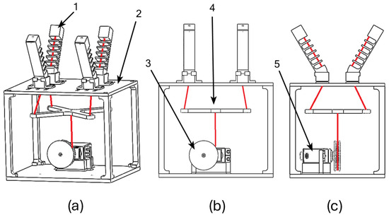
Figure 1.
Gripper’s structure: (a) isometric view (1: soft finger, 2: adjustable palm); (b) lateral view (3: pulley, 4: cross-shaped differential system); (c) front view (5: servomotor).
2.1. Finger Design and Characterization
The fingers are monolithic deformable 3D-printed structures made of Polyethylene Terephthalate Glycol (PETG) and have already been characterized in a previous work to evaluate their deformability [19]. The finger design was conceived to resemble a spring between two rigid phalanges, as Figure 1 and Figure 2 report. This structure lends the fingers a characteristic elasticity and deformation. The most significant finger dimensions are shown in Figure 2. The stiffness k of the robotic fingers was evaluated both through experimental tests and simulations, considering a maximum applied force of 4 N. For this characterization, the finger base was rigidly constrained, implementing the cantilever beam model.
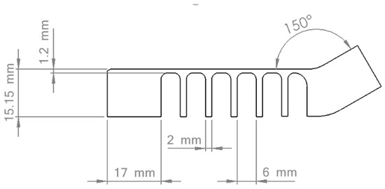
Figure 2.
Finger dimensions.
The fingers were experimentally characterized using a test bench equipped with a digital dynamometer (IMADA ZTA50, IMADA Co.,Ltd., Toyohashi, Japan), as represented in Figure 3a. A vertical load was applied to the fingertip through the tip of the dynamometer to replicate the finger flexion and the displacement values for different increasing loads were registered. The experimental force–displacement curve was built by interpolating the measured points (Figure 3d). The same experiment was then replicated with an FEM analysis (Figure 3b,c), obtaining a theoretical force–displacement curve as in Figure 3d. The material properties were incorporated into the simulation environment and tuned to fit the experimental curves. The selected density reflects the infill percentage used during the 3D printing of the fingers. In particular, the solid mesh comprises 10,154 elements of 2.26 mm with a mesh density of 0.88 element mm (Figure 3b). The material properties are Young’s modulus 2110 N/mm2, Poisson’s ratio 0.37, shear modulus 318.9 N/mm2, density 1270 kg/m3, tensile strength 50 N/mm2, compressive strength 73 N/mm2, and tensile yield strength 26 N/mm2. Based on the material characteristics and experimental results, a linear static analysis was performed on the PETG finger to evaluate its deformation under load.
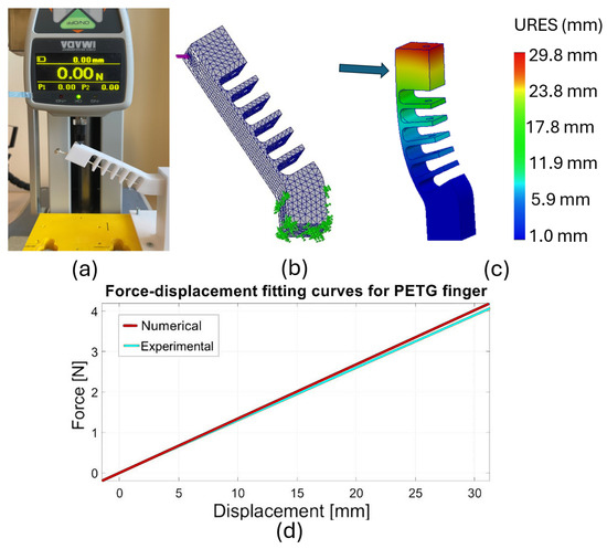
Figure 3.
Finger mechanical characterization: (a) experimental setup; (b) mesh, load, and constraints, (c) FEM simulation; (d) experimental and theoretical force–displacement curves.
In addition, the trajectories of the fingers were experimentally assessed, as reported in Figure 4, by applying known tensile forces to the tendon and tracking the motion of a specific point on the fingertip. For this purpose, a dedicated experimental set-up was implemented, in which the tendon was attached to a digital dynamometer. The fingertip trajectory was mapped incrementally, recording the corresponding force value at each position. This approach allowed for the reconstruction of the trajectory curves and a correlation between the tendon force and the resulting vertical displacement at each step.
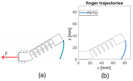
Figure 4.
Finger trajectories: (a) experimental setup conditions (red arrow represents the force applied on the finger tendon); (b) experimental evaluation of finger trajectories.
All these experiments and simulations allowed us to characterize the mechanical behavior of fingers and establish a basis for further predictions and analyses. In fact, in this paper, the same experiments and simulations were replicated for the cross-structure of the differential system with the aim of improving its mechanical behavior and effectiveness through a structural design optimization.
3. Proposed Differential System and Preliminary Characterization
3.1. Experimental Characterization of the Differential System
The proposed differential system was conceived to act as a seesaw mechanism and was designed with a 3 mm thick cross-shaped structure, and 3D printed in PETG, as shown in Figure 5a. It presents a certain flexibility that results in a specific curvature of the component occurring once it stands under significant loads. In the initial analysis of the differential system integrated into the four-finger gripper, full-grasping tests were performed using the setup represented in Figure 5b. An object was held with only two opposite fingers that lock immediately under full load, whereas the other two opposite fingers were free to move indefinitely until contact between finger pads. In these experiments, the servomotor was actuated at maximum speed by using an on/off remote command. It was observed that the cross-shaped structure underwent significant deformation and curvature when the fingers reached full flexion (full-grasp condition), as illustrated in Figure 5b.
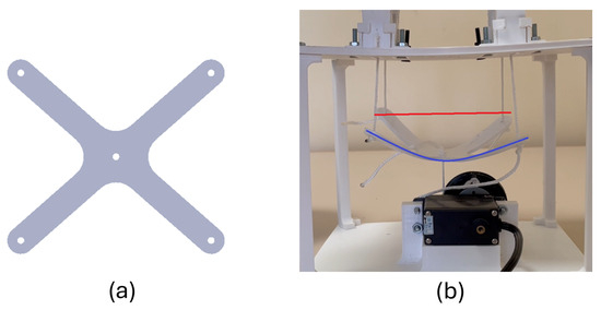
Figure 5.
Differential structure and preliminary analysis: (a) top view of the differential system, (b) curvature of the structure at full grasp (blue line) and at rest (red line).
Furthermore, another observation that emerged from this test was that the differential system slightly tilted during grasping, by about 5.5 degrees, according to the seesaw working principle. If the differential was infinitely rigid, the tilt would be the only possible movement necessary to accomplish a compliant and adaptive grasp, allowing for free movements of the fingers and the ability to pick up free-form objects. In contrast, in the shown differential system, the tilt is accompanied by deformation, which reduces the traction force on the tendons, but still allows for adaptive and compliant grasping. This behavior indicated that the system functioned as a force reducer, progressively modulating the transmission of force. While such compliance can be advantageous in delicate grasping tasks, allowing for smoother and more controlled force application, it also highlights a potential trade-off in terms of structural stability under higher loads.
To evaluate the mechanical behavior of the cross differential system, and the bending stiffness, an experimental force–displacement curve was obtained. The experimental set up was prepared connecting the differential to a digital dynamometer (IMADA ZTA50, IMADA Co., Ltd., Toyohashi, Japan) locking the four output tendons and connecting the input tendon to the dynamometer, as will be reported in the following sections.
The test was carried out by applying a force with steps of 1 N to 20 N and evaluating the displacement, obtaining the force–displacement curve from which the elastic properties of the component can be extracted.
3.2. Preliminary FEM Model and Theoretical Characterization
The FEM model was developed in Ansys (Ansys, Inc., Canonsburg, Pennsylvania, USA) and tried to replicate the gripper’s real actuation conditions, considering a fixed boundary in the center of the differential structure and applying the forces (1 N per wing) on the tip of the four wings. The forces were applied with a ramp lasting 1 s. These experimental conditions are reported in Figure 6a. The mesh grid was generated using a biased distribution approach, combining tetrahedral and swept meshing techniques. Specifically, sweepable bodies were identified and meshed using the swept method, while tetrahedral meshing was applied to the remaining regions. The biased grid distribution obtained is composed of tetrahedral elements of 1 mm, and the mesh comprises 8670 elements (Figure 6b). A mesh convergence study was conducted to ensure the reliability and accuracy of the simulation results.
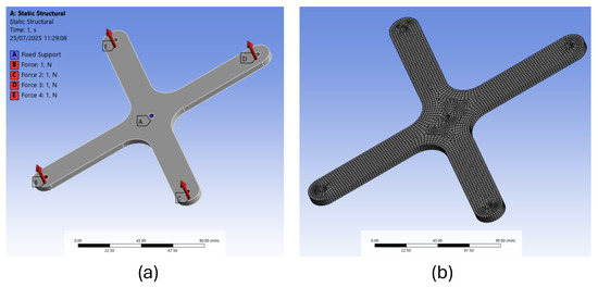
Figure 6.
FEM model of the cross structure: (a) boundary conditions; (b) mesh grid.
The simulation environment was configured to include the mechanical properties of the material, which were calibrated to match the experimental force–displacement curves. The material density was adjusted to reflect the infill percentage used in the 3D-printed differential, based on the actual measured weight of the component.
In particular, the material density was found to be 780 kg/m3 and the Young’s modulus 830 N/mm2. The other material properties were as follows: Poisson’s ratio 0.39, shear modulus 298.8 N/mm2, tensile strength 57.5 N/mm2, and tensile yield strength 52.44 N/mm2.
Based on this validated model, where the material properties were tuned to fit the experimental results, it was possible to perform a linear static analysis and a thorough evaluation of the stresses that act on the component, identifying the critical points where potential structural issues may arise.
Figure 7a reports the results in terms of von Mises equivalent stress and Figure 7b reports the preliminary results in terms of deformation. It can be observed that the most probable structural failure points are located at the base of each of the four wings of the cross, specifically in the regions corresponding to the connections with the central structure. This failure mode is considered consistent with expectations and was confirmed by previous braking tests conducted on the differential system. These results were useful to conceive a structural optimization of the component with the objective of optimizing the geometry to obtain lower and more uniformly distributed stresses, maintaining the same thickness.
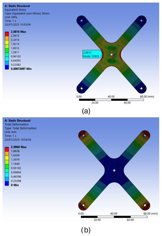
Figure 7.
Preliminary FEM results: (a) von Mises equivalent stress; (b) deformation.
4. Structural Optimization Based on FEM Analyses
The optimization process involved a topology optimization method that kept the thickness constant and applied the force and structural boundaries as in the preliminary FEM analysis, as reported in Figure 8a
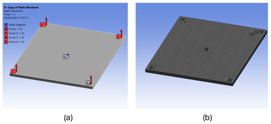
Figure 8.
FEM model of the square shell: (a) boundary conditions; (b) mesh grid.
Structural optimization can be carried out by modifying the geometry, the thickness, or both. Varying only the thickness, the structure would present the same failure points and stress distribution with improved resistance. Conversely, optimizing the geometry while keeping the thickness constant results in a more uniform stress distribution by reducing localized stress concentrations. Simultaneously altering both geometry and thickness would hinder a clear and meaningful comparison between the two design approaches.
The topological optimization started with a square shell structure with the same thickness as the original component. The mesh grid of the square shell comprises 30,276 elements of 1 mm (Figure 8b). For every step of the topology optimization procedure, a static structural study was performed to check the stress distribution and deformation. After simulations with different mass removal boundaries, it was established that around 50% or more mass removal would compromise the entire structure and would result in a non-functional component, while removing less than 40% the structure would result in it being too rigid and would have no apparent advantages. By iteration, a 45% mass removal boundary was chosen as a good compromise between flexibility and stress distribution. Therefore, in the optimization process, 45% of the material of the square shell was removed and a subtractive extrusion was imposed to the model. The result of this optimization is represented in Figure 9. After this first optimization, the resulting model was manually refined to obtain regular edges.
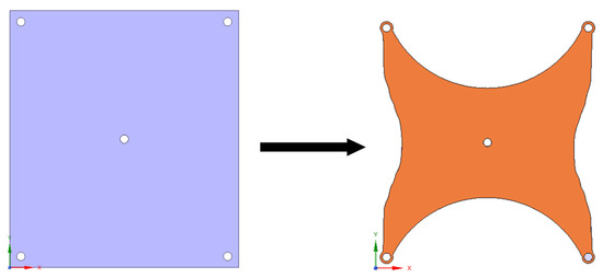
Figure 9.
Differential geometry optimization starting from a square shell.
Figure 10a reports the boundary and load conditions used for optimized structure, while the mesh grid is represented in Figure 10b and is composed of 14,816 elements of 1 mm. To validate the accuracy of the FEM model, a mesh sensitivity analysis was carried out, confirming that the results were not significantly affected by the element size.
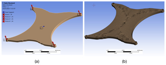
Figure 10.
FEM model of the optimized structure: (a) boundary conditions; (b) mesh grid.
The results of the static analysis performed on the optimized structure show that with the topology improvement, the material was strategically distributed to achieve a uniform stress distribution throughout the structure, minimizing weak points and enhancing overall resistance. This optimized configuration allows the structure to support heavier loads during deformation, which is essential for absorbing dynamic forces and preventing sudden failures. The improved rigidity contributes to greater durability and performance under varying conditions. One can clearly observe the differences in stress distribution and extent in Figure 11a, where the lower and more uniformly distributed stresses ascribable to the new optimized geometry are reported, highlighting the effectiveness of this new design approach. Figure 11b reports the FEM results in terms of deformation.
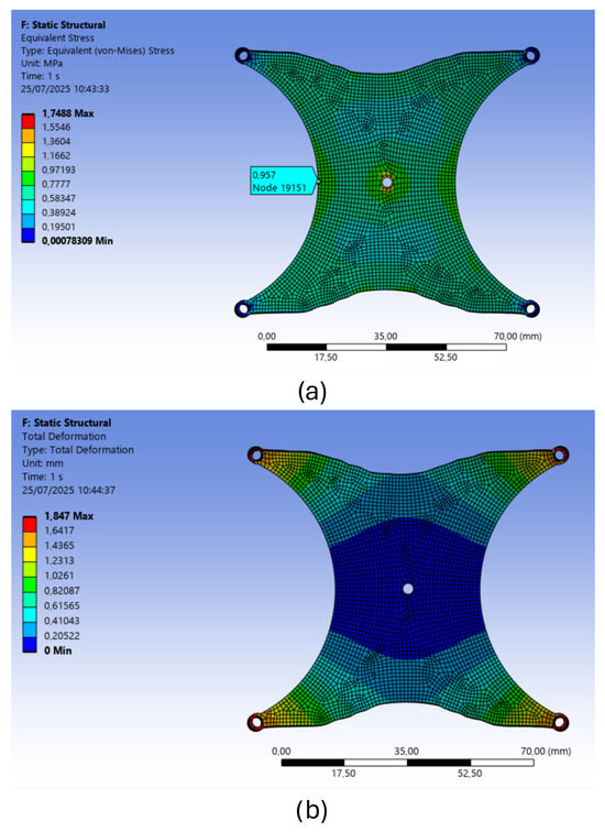
Figure 11.
FEM results of the optimized structure: (a) von Mises stress distribution; (b) deformation.
5. Experimental Characterization of the New Differential System and Comparison of Results
A thorough comparison between the experimental results of the original cross-structure and the optimized design was performed to rigorously evaluate the improvements achieved with the new differential configuration.
The tests aimed at the stiffness characterization were performed using the same methods and instruments, as described in Section 2.1 and as represented in Figure 12a. In addition, a practical measurement procedure utilizing video tracking techniques was implemented to assess the deformations over time. The measurements performed with the digital dynamometer provided precise force–displacement data, allowing a quantitative assessment of the stiffness and deformation characteristics. Meanwhile, video tracking techniques allowed for the observation of real-time motion and deformation under varying loads, providing qualitative and quantitative insights into different behavioral patterns. By combining these two measurement approaches, a more detailed evaluation of the system’s performance was achieved. The results related to rigidity, for both of the two studied differential’s structures, are illustrated in Figure 12b.
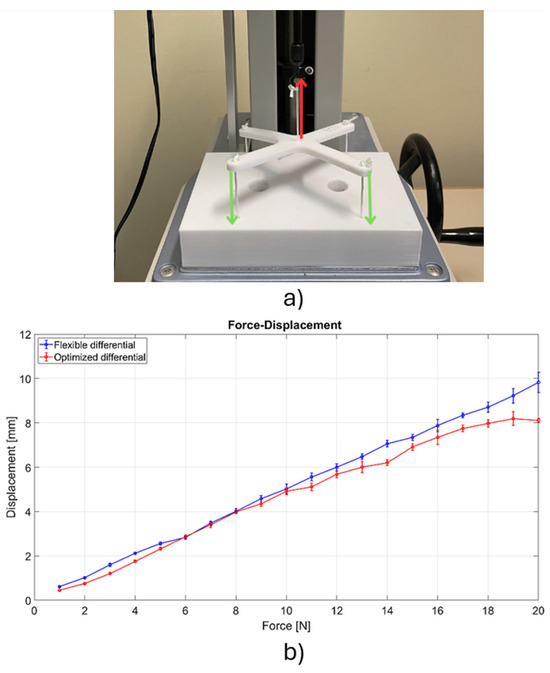
Figure 12.
Comparison of rigidity between the two differential systems: (a) experimental setup (red arrow represents force exerted by the dynamometer on the differential via the tendon, green arrows represent reaction forces due to boundary conditions), (b) experimental force–displacement curves.
From Figure 12, one can immediately observe that the stiffness of the optimized structure is non-linear, particularly when compared to its more flexible twin, and this behavior becomes more evident at higher load levels. This trend indicates that the optimized differential system does not exhibit a constant stiffness with increasing forces. Nevertheless, to provide a quantitative evaluation of the different flexibilities of the two differentials, the stiffness was calculated by approximating both the curves with lines. The results showed that the cross and optimized structures have, respectively, a stiffness of 2.04 N/mm and 2.47 N/mm. A behavior in agreement with these characteristic curves was further studied by performing full-grasp experiments with the two differential systems mounted on the robotic gripper. The test setup comprised a phone camera with 1080p resolution at 60 fps and a tripod to support the phone that was placed perpendicular to the gripper. The gripper was placed on a rigid table and remotely actuated by a controller with two switches. The video tracking software that was used was the Tracker—Video Analysis and Modeling Tool v. 6.2.0 (Open Source Physics, USA National Science Foundation, Virginia (USA)), which allowed us to record videos using arbitrary reference systems and to track specific points during motion. The results of these tests in terms of maximum displacement are reported in Figure 13, where the operation of the gripper equipped with the two types of differential structure is illustrated, revealing a notable contrast in deformations.
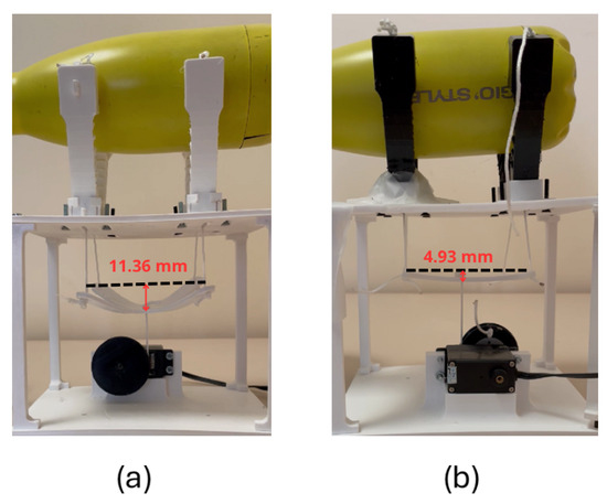
Figure 13.
Full grasp comparison: (a) flexible differential (b) optimized differential.
In addition, the tracking study allowed us to analyze displacements and forces in the time-domain for both of the two differential systems. For this purpose, a time–displacement curve was graphed using the data obtained by the tracking study, as reported in Figure 14. Thus, the transient phase in the differential’s response up to full grasp can be displayed. From this result and considering the characteristic force–displacement curves of the two differentials, a time-based force curve was obtained, as shown in Figure 15. This curve represents the rapidity with which it reached the maximum actuation force, the full-grasping time, and the force transfer efficiency of the two differentials.
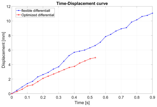
Figure 14.
Displacement transient during a full grasp.
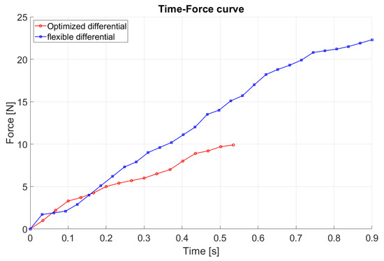
Figure 15.
Actuation force transient during a full grasp.
From these results, some observations can be made. In full grasp, while the contact force required to secure the object is the same when using both the differential systems, the motor that moves the flexible differential requires significantly higher forces, as one can observe in Figure 15.
In fact, considering that the maximum displacement of the flexible differential is much higher (11.36 mm vs. 4.93 mm) and taking into account the force–displacement curves of both the differentials, one can observe that, for the same task, the flexible differential needs the motor to output a force of 22.3 N, whereas for the optimized differential, the motor exerts a force of 9.8 N. The optimized differential is also faster in terms of reaching full grasp of the object, taking 0.54 s to achieve grasping compared to 0.89 s for the flexible differential, which results in a speed increase of 39.4%.
This is due to a portion of the motor torque being absorbed in deforming the differential’s structure, leading to energy dissipation and reduced efficiency (Figure 13a). In contrast, the optimized differential structure shows a different behavior. It demands less force from the motor, minimizing deformation and ensuring a more effective energy transfer. As a result, the motor operates with greater efficiency, requiring less power to achieve a firm and stable grasp. This refined design not only improves the overall performance of the gripper, but also contributes to a more energy efficient mechanism, making it better suited for the precise and controlled manipulation of objects with fine contact force tuning.
Other full-grasping tests with different objects confirmed these behaviors of the two differentials, showing that to secure various objects, the flexible differential presents higher deformations and requests higher actuation forces from the motor. This behavior can be observed in Figure 16, where three different grasps are presented using the gripper with the two differentials. A stapler was used as an example of non-symmetrical object, while a steel bottle was used both as a purely asymmetrical object, using just two opposite fingers, and as a cylindrical object, using all the fingers. In all these experiments, the lower displacement of the optimized differential can be observed.
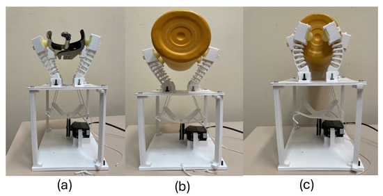
Figure 16.
Full grasp comparison for various objects: (a) non-simmetrical object (b) purely asymmetrical object (c) cylindrical object.
Figure 17 shows the lateral view of the three experiments conducted with the flexible cross differential. From this picture, some observations about the object centering can be argued. One can observe that the original differential, even if highly flexible, did not cause centering issues during grasping. This suggests that the differential deformability does not affect the symmetry of the finger movements.
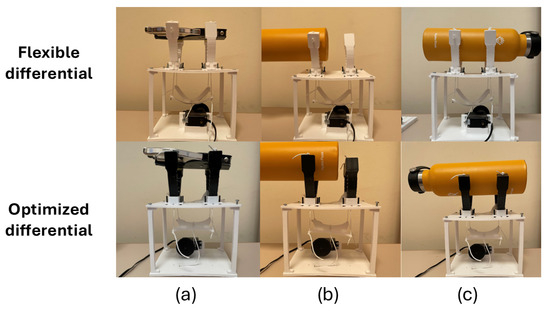
Figure 17.
Full grasp tests comparison with flexible differential (lateral view) (a) non-simmetrical object; (b) cylindrical object; (c) purely asymmetrical object.
6. Conclusions
In this paper, the structural optimization of a seesaw differential system for underactuated robotic grippers was performed to enhance the grasping efficiency. Considering an initial flexible cross-structure, various numerical evaluations and experiments were carried out to characterize the mechanical behavior of the component and assess the critical failing points. An FEM model was developed and validated as a starting point to obtain an optimized geometry of the differential structure. The optimized version of the differential system showed a notable difference in behavior with respect to the previous one, successfully achieving both desired objectives: maintaining sufficient stiffness while preventing excessive stress in critical areas. The new optimized structure was further experimentally characterized and tested in full-grasping conditions. Several full-grasp tests were performed using different objects to evaluate the grasping performance in terms of compliance and secure hold, considering freeform, symmetric, and asymmetric geometries.
In particular, the new optimized differential shows an increase in stiffness of 21.08%, which affects the differential behavior in terms of the actuation force needed for full grasp. Indeed, analysis of the force–displacement curves indicates that the optimized differential requires 56.1% less actuation force compared to the initial design. Moreover, the time required to complete a full grasp after initial contact is a relevant performance metric: the optimized differential is 39.4% faster (0.89 s vs. 0.54 s). Despite this improvement, it retains a certain degree of flexibility, which allows the forces transferred during finger contact to be distributed over a longer period of time. In contrast, a fully rigid differential would result in an almost instantaneous actuation, concentrating the forces in a much shorter time span.
These results demonstrate the effectiveness of the new differential system, which shows a non-linear stiffness and maintains the same level of grasping compliance while ensuring a secure hold and improving gripper performance in terms of required actuation force. From this perspective, the structure functions as a force reducer, effectively balancing rigidity and flexibility to optimize performance without compromising structural integrity. Furthermore, despite the faster execution of the grasping operation, a certain degree of smoothness and gradual force application is still preserved. Therefore, the new differential structure retains the advantages of a flexible design while significantly improving overall efficiency.
Future directions will be focused on extending the performance study of the new differential system. For example, the theoretical and experimental fatigue study will be approached together with the evaluation of contact forces and the grasping tests to assess the pick repeatability when objects are grasped from the same position. Other tests will be undertaken to study the differential behavior under torsional loads and varying grasping speeds.
Author Contributions
Conceptualization, S.L. and M.C.V.; methodology, S.L. and M.C.V.; software, V.B.; validation, S.A.,V.B., S.L. and M.C.V.; formal analysis, S.L.; investigation, S.A., V.B.; resources, V.B.; data curation, V.B.; writing—original draft preparation, S.A.; writing—review and editing, S.L. and M.C.V.; visualization, S.A.,V.B., S.L. and M.C.V.; supervision, S.L. and M.C.V.; project administration, M.C.V. All authors have read and agreed to the published version of the manuscript.
Funding
This work has been funded by the European Union—NextGenerationEU, Mission 4, Component 2, under the Italian Ministry of University and Research (MUR) National Innovation Ecosystem grant ECS00000041—VITALITY-CUP J97G22000170005.
Data Availability Statement
The original contributions presented in this study are included in the article. Further inquiries can be directed to the corresponding authors.
Conflicts of Interest
The authors declare no conflicts of interest.
References
- Shintake, J.; Cacucciolo, V.; Floreano, D.; Shea, H. Soft robotic grippers. Adv. Mater. 2018, 30, 1707035. [Google Scholar] [CrossRef]
- Otti, M.; Monsalve, D.; Chapelle, F.; Bouzgarrou, C.; Lapusta, Y. Recent Improvements in the Development of Soft Grippers Capable of Dexterous Manipulation. Appl. Sci. 2025, 15, 275. [Google Scholar] [CrossRef]
- Navas, E.; Fernández, R.; Sepúlveda, D.; Armada, M.; Gonzalez-de Santos, P. Soft Grippers for Automatic Crop Harvesting: A Review. Sensors 2021, 21, 2689. [Google Scholar] [CrossRef] [PubMed]
- Perez-Sanchez, V.; Garcia-Rubiales, F.J.; Nekoo, S.R.; Arrue, B.; Ollero, A. Modeling and Application of an SMA-Actuated Lightweight Human-Inspired Gripper for Aerial Manipulation. Machines 2023, 11, 859. [Google Scholar] [CrossRef]
- Sun, J.; Chen, C.; Wang, L.; Liang, Y.; Chen, G.; Xu, M.; Xi, R.; Shao, H. Design and Simulation Experiment of Rigid-Flexible Soft Humanoid Finger. Machines 2022, 10, 448. [Google Scholar] [CrossRef]
- Raparelli, T.; Mattiazzo, G.; Mauro, S.; Velardocchia, M. Design and development of a pneumatic anthropomorphic hand. J. Robot. Syst. 2000, 17, 1–15. [Google Scholar] [CrossRef]
- Chen, C.; Liang, Y.; Sun, J.; Lin, C.; Wen, Y. Adaptive pneumatic soft gripper with embedded flexible bending sensor. Ind. Robot Int. J. Robot. Res. Appl. 2024, 51, 358–368. [Google Scholar] [CrossRef]
- Ramírez-Montañez, J.A.; Rangel-Magdaleno, J.d.J.; Aceves-Fernández, M.A.; Ramos-Arreguín, J.M. Modeling of Particulate Pollutants Using a Memory-Based Recurrent Neural Network Implemented on an FPGA. Micromachines 2023, 14, 1804. [Google Scholar] [CrossRef]
- Malik, S.; Shafqat, W.; Lee, K.T.; Kim, D.H. A Feature Selection-Based Predictive-Learning Framework for Optimal Actuator Control in Smart Homes. Actuators 2021, 10, 84. [Google Scholar] [CrossRef]
- Logozzo, S.; Valigi, M.C. A Gripper with Wave Joint Fingers for Precision Grasping. In Advances in Italian Mechanism Science, Proceedings of the International Conference of IFToMM ITALY, Torino, Italy, 11–13 September 2024; Quaglia, G., Boschetti, G., Carbone, G., Eds.; Springer: Cham, Switzerland, 2024; pp. 492–499. [Google Scholar]
- Zhu, K.; Lueth, T.C.; Sun, Y. Design of FDM-printable tendon-driven continuum robots using a serial S-shaped backbone structure. Biomim. Intell. Robot. 2025, 5, 100188. [Google Scholar] [CrossRef]
- Denizon, D.; Dogru, S.; Marques, L. Improving Grasping Performance of Underactuated Two Finger Robotic Hands Using Variable Stiffness. In Proceedings of the 2024 7th Iberian Robotics Conference (ROBOT), Madrid, Spain, 6–8 November 2024; pp. 1–6. [Google Scholar] [CrossRef]
- Wang, W.; Ahn, S.H. Shape Memory Alloy-Based Soft Gripper with Variable Stiffness for Compliant and Effective Grasping. Soft Robot. 2017, 4, 379–389. [Google Scholar] [CrossRef]
- Achilli, G.M.; Logozzo, S.; Malvezzi, M.; Valigi, M.C. Underactuated embedded constraints gripper for grasping in toxic environments. SN Appl. Sci. 2023, 5, 96. [Google Scholar] [CrossRef]
- Achilli, G.M.; Logozzo, S.; Valigi, M.C.; Salvietti, G.; Prattichizzo, D.; Malvezzi, M. Underactuated Soft Gripper for Helping Humans in Harmful Works. Mech. Mach. Sci. 2022, 108 MMS, 264–272. [Google Scholar] [CrossRef]
- Kwok, T.M.; Zhang, B.; Chow, W.T. A Wearable Stiffness-Rendering Haptic Device with a Honeycomb Jamming Mechanism for Bilateral Teleoperation. Machines 2025, 13, 27. [Google Scholar] [CrossRef]
- Dzedzickis, A.; Petronienė, J.J.; Petkevičius, S.; Bučinskas, V. Soft Grippers in Robotics: Progress of Last 10 Years. Machines 2024, 12, 887. [Google Scholar] [CrossRef]
- Hirose, S.; Umetani, Y. The development of soft gripper for the versatile robot hand. Mech. Mach. Theory 1978, 13, 351–359. [Google Scholar] [CrossRef]
- Burini, V.; Logozzo, S.; Valigi, M.C. Design and Characterization of a New Soft Robotic Gripper. In Proceedings of the International Conference of IFToMM ITALY, Torino, Italy, 11–13 September 2024; Springer: Cham, Switzerland, 2024; pp. 474–482. [Google Scholar]
- Zhang, D.; Zhang, W.; Yang, H.; Yang, H. Application of Soft Grippers in the Field of Agricultural Harvesting: A Review. Machines 2025, 13, 55. [Google Scholar] [CrossRef]
- Tiboni, M.; Loda, D. Force-Optimized Monolithic Pneunets Soft Actuators: Design, Simulation and Characterization. Int. J. Mech. Control 2025, 26. [Google Scholar] [CrossRef]
- Rodinò, S.; Lago, F.; Malyshev, D.; Carbone, G. Design of a Movable Palmfor A 3-Fingers Robotic Hand. Int. J. Mech. Control 2023, 24, 177–188. [Google Scholar]
- Espinosa-Garcia, F.; Arias-Montiel, M.; Lugo González, E.; Tapia-Herrera, R.; Ceccarelli, M. A Review and Classifiacation of Robotic Hands Focused on Palm STRUCTURE. Int. J. Mech. Control 2022, 23, 45–59. [Google Scholar]
- Isakhani, H.; Nefti-meziani, S.; Davis, S.; Isakhani, H. A Bioinspired Underactuated Dual Tendon-Based Adaptive Gripper for Space Applications. In Proceedings of the 2023 IEEE/RSJ International Conference on Intelligent Robots and Systems (IROS), Detroit, MI, USA, 1–5 October 2023; pp. 2447–2454. [Google Scholar] [CrossRef]
- Antonelli, M.G.; Beomonte Zobel, P.; Durante, F.; Gaj, F. Development and testing of a grasper for NOTES powered by variable stiffness pneumatic actuation. Int. J. Med. Robot. Comput. Assist. Surg. 2017, 13, 1796. [Google Scholar] [CrossRef]
- Dechev, N.; Cleghorn, W.; Naumann, S. Multiple finger, passive adaptive grasp prosthetic hand. Mech. Mach. Theory 2001, 36, 1157–1173. [Google Scholar] [CrossRef]
- Antonelli, M.G.; Zobel, P.B.; D’ambrogio, W.; Durante, F. Design methodology for a novel bending pneumatic soft actuator for kinematically mirroring the shape of objects. Actuators 2020, 9, 113. [Google Scholar] [CrossRef]
- Birglen, L.; Gosselin, C. Force Analysis of Connected Differential Mechanisms: Application to Grasping. Int. J. Robot. Res. 2006, 25, 1033–1046. [Google Scholar] [CrossRef]
- Achilli, G.M.; Logozzo, S.; Valigi, M.C. An Educational Test Rig for Kinesthetic Learning of Mechanisms for Underactuated Robotic Hands. Robotics 2022, 11, 115. [Google Scholar] [CrossRef]
- Khatik, V.; Saxena, A. On Optimal Tendon Routing Based Design of Biologically Inspired Underactuated Hand Exoskeleton for Gross Grasping. IEEE Trans. Med. Robot. Bionics 2024, 6, 600–617. [Google Scholar] [CrossRef]
- Bajaj, A.; Jain, V.; Kumar, P.; Unal, A.; Saxena, A. Soft Hand Exoskeleton for Adaptive Grasping Using a Compact Differential Mechanism. In Mechanism and Machine Science: Select Proceedings of Asian MMS 2018, Bengaluru, India, 17–18 December 2018; Springer: Berlin/Heidelberg, Germany, 2021; pp. 733–746. [Google Scholar] [CrossRef]
- Zhao, C.; Liu, M.; Huang, X.; Ma, Y.; Zhang, B.; Li, H.; Huang, Q.; Jiang, Z. Adaptive and Dexterous Tendon-Driven Underactuated Finger Design With a Predefined Elastic Force Gradient. IEEE/ASME Trans. Mechatronics 2023, 29, 1622–1633. [Google Scholar] [CrossRef]
- Park, W.; Seo, S.; Bae, J. A Hybrid Gripper With Soft Material and Rigid Structures. IEEE Robot. Autom. Lett. 2018, 4, 65–72. [Google Scholar] [CrossRef]
- Shahmohammadi, M.; Liarokapis, M. A Series Elastic, Compact Differential Mechanism: On the Development of Adaptive, Lightweight Robotic Grippers and Hands. In Proceedings of the 2021 IEEE/RSJ International Conference on Intelligent Robots and Systems (IROS), Prague, Czech Republic, 27 September–1 October 2021; pp. 6110–6116. [Google Scholar] [CrossRef]
- Sun, X.; Gan, C.; Chen, W.; Chen, W.; Liu, Y. Design of a Three-Finger Underactuated Robotic Gripper Based on a Flexible Differential Mechanism. In Intelligent Robotics and Applications, Proceedings of the International Conference on Intelligent Robotics and Applications; Yang, H., Liu, H., Zou, J., Yin, Z., Liu, L., Yang, G., Ouyang, X., Wang, Z., Eds.; Springer: Singapore, 2023; pp. 546–557. [Google Scholar]
- Xu, K.; Liu, H. Continuum Differential Mechanisms and Their Applications in Gripper Designs. IEEE Trans. Robot. 2016, 32, 754–762. [Google Scholar] [CrossRef]
- Antonelli, M.G.; Beomonte Zobel, P.; Mattei, E.; Stampone, N. Mechanical Design, Manufacturing, and Testing of a Soft Pneumatic Actuator with a Reconfigurable Modular Reinforcement. Robotics 2024, 13, 165. [Google Scholar] [CrossRef]
- Dong, H.; Asadi, E.; Qiu, C.; Dai, J.; Chen, I.M. Geometric design optimization of an under-actuated tendon-driven robotic gripper. Robot. Comput.-Integr. Manuf. 2018, 50, 80–89. [Google Scholar] [CrossRef]


Disclaimer/Publisher’s Note: The statements, opinions and data contained in all publications are solely those of the individual author(s) and contributor(s) and not of MDPI and/or the editor(s). MDPI and/or the editor(s) disclaim responsibility for any injury to people or property resulting from any ideas, methods, instructions or products referred to in the content. |
© 2025 by the authors. Licensee MDPI, Basel, Switzerland. This article is an open access article distributed under the terms and conditions of the Creative Commons Attribution (CC BY) license (https://creativecommons.org/licenses/by/4.0/).