1. Introduction
Brush clearing involves the removal of unwanted and spontaneous vegetation, and it is performed for several purposes. Beyond improving the aesthetics and accessibility of areas, this practice is essential in cultivated fields for preventing wild vegetation from competing with crops for water, light, and nutrients. In other contexts, it reduces the risk of wildfires, ensures clear visibility along roadsides, and aids in maintaining proper water flow in drainage channels during heavy or prolonged rainfall. The continuous clearing operation avoids the thickening of bushes and allows for the growth of different and abundant herbaceous species suitable for grazing [
1]. An investigation carried out in a savannah has shown that mechanical clearing favours the development of herbaceous plants and retains the species with high woody density, favouring both the overall abundance and the composition of ungulate species [
2].
The tools used for brush clearing depend on the type of vegetation and on the size of the area to treat. Some information on the cutting resistance of various plant species and the corresponding cutting tools to be adopted can be found in [
3]. Although there is an extensive bibliography on grass cutting [
4,
5] and various types of crops [
6,
7], studies focused on brush cutting are relatively rare, likely due to the vast number of plant varieties and their combinations.
Brush clearing can be performed by cutting the vegetation and collecting the residues for disposal. Alternatively, a mulching technique [
8] can be used, where the vegetation is repeatedly cut and shredded, and the fragments are left on the ground. This method has multiple benefits: it reduces soil water evaporation, naturally fertilizes the soil, and eliminates the costs associated with residue disposal.
The equipment used for brush clearing typically includes a cutting head powered by a motor, either thermal or electric. The cost of agricultural brush clearing decreases as the size of the machinery increases, up to a point, over which it increases continuously [
9]. To clear difficult areas, it is convenient to have machines that are not very large so that they can maneuver around obstacles. Difficult areas can be defined as environments that include unstructured terrain, which is characterized by surface irregularities such as holes, bumps, slopes, steps, rocks, and by soils with poor bearing capacity or reduced friction.
Furthermore, in areas near cultivated fields, it is preferable to avoid machinery that emits polluting gases. The European Commission, to reduce the impact of emissions on the climate, has set the ambitious goal of reducing emissions by 55% by 2030 and of becoming “carbon neutral” by 2050. To achieve this goal, agricultural machinery will also gradually have to be equipped with electric motors.
This paper investigates the possibility of adopting a six-wheeled mobile robot equipped with a kinematic rocker–bogie suspension system [
10,
11,
12], featuring a robotic arm with a cutting head as the end effector, to reach areas between obstacles. This kind of wheeled platform has been employed for Martian exploration since 1997 [
13,
14]. Compared to dynamic suspension systems (with springs and shock absorbers), kinematic suspensions allow each wheel to have greater vertical travel to better adapt them to irregularities of the soil; in this way, each wheel remains in contact with the ground, contributing to supporting the weight of the rover and providing traction with a lower propensity to slip and sink [
15,
16].
Over time, vehicles equipped with such suspensions have also been proposed for land applications when they need to move on rough terrain, as occurs in search and rescue operations in areas hit by disasters, such as earthquakes or landslides, characterized by the presence of rubble and unstable terrain [
17]; for military reconnaissance and ordnance clearance operations; for maintenance and inspection operations of industrial or civil infrastructures, such as nuclear power plants, bridges, dams, pipelines, etc., if there is a need to overcome obstacles such as debris or differences in level; for wheelchairs that can go up and down stairs [
18]; and in agriculture [
19,
20], although cultivated areas are often characterized by sufficiently regular soil. In this last application, mobile manipulator robots are used for automatic fruit and vegetable harvesting, plant pruning, sowing or crop monitoring [
21,
22].
A robot brush cutter of this type could be adopted to clean up areas adjacent to cultivated fields if characterized by significant irregularities due to the presence of rocky areas, steep slopes, etc. Sometimes, these unfavourable characteristics depend on the presence of infrastructures such as railway embankments, rainwater retention basins, solar or wind farms, etc.
The robotic arm can position the cutting head differently with respect to the rover, determining the shift in the robot’s centre of mass. This peculiarity can be adopted to increase the robot’s stability or to redistribute the load between the wheels to increase the traction capacity or to overcome an obstacle.
Since such mobile robots must move on terrains that could be soft or slippery, to prevent the robot from entering a trap zone from which it cannot escape due to wheel slipping or sinking, the feasibility of assessing ground grip conditions is explored by using the front wheels as tactile sensors. Keeping the four rear wheels stationary, it is assumed that the driving torque of the front wheels cannot move the robot; in this condition, the torque of the front wheels can be increased up to the slip limit, thereby identifying key soil parameters. The slip limit is influenced by the surface roughness, slope gradient, soil type, vegetation density, presence of rocks, weather conditions, etc. In case of unfavourable conditions, the rover can reverse using the rear wheels and test an alternative path. To this end, the rover must be instrumented to measure the driving torque on the front wheels and the load acting on them. The driving torque can be determined by monitoring the current intensity supplied to the motors, while the load on the front wheels can be estimated using strain gauges glued to the suspension links. The strain gauge signal, together with a rotation signal of the suspension links, allows for the detection of the load acting on the front wheels, which may vary due to ground irregularities. The onset of wheel slip is detected by changes in the deformation of the suspension links, which corresponds to a shift from grip to slip conditions or from the sudden variation in voltage absorbed by the motor if controllable in current.
For mobile robots, it is essential to identify the environment in which they move to assess whether they can navigate safely and efficiently. Autonomous navigation requires the perception of the environment as precisely as possible to verify whether it can be crossed; this can be achieved through proprioceptive sensors that monitor the state and behaviour of the robot itself, and exteroceptive sensors that detect information external to the robot, monitoring the surrounding environment or the relationship between the system and the outside. The proposed system uses the measurement of the deformation of the suspension links to estimate the characteristics of the wheel–ground interaction and can be a useful tool that, together with other sensors, can provide a more accurate indication of the traversability of an area.
This article is a revised and expanded version of a paper entitled
A feasibility analysis of a six-wheel drive rover for bush clearing operations [
23], which was presented at
The 5th IFToMM ITALY Conference, 11–13 September 2024, Torino, Italy.
2. Brush Clearing Rover Description
For brush clearing operations, the use of wheeled rovers is considered as, in comparison with existing tracked vehicles, they are not polluting and less expensive both in terms of initial cost and maintenance costs; furthermore, they are lighter, so the pressure on the soil is not high if they are equipped with an adequate number of wheels with suitable dimensions. Considering that each wheel can exert a tractive force proportional to its weight, even if some wheels have poor grip, the other wheel can exert the necessary traction force. In the field of space exploration, it has been seen that a six-wheeled rover represents a good compromise between performance, cost, and ease of management.
In the following, the main characteristics of a rover with six drive wheels, equipped with rocker–bogie suspension, are described.
2.1. Rover Geometric Characteristics
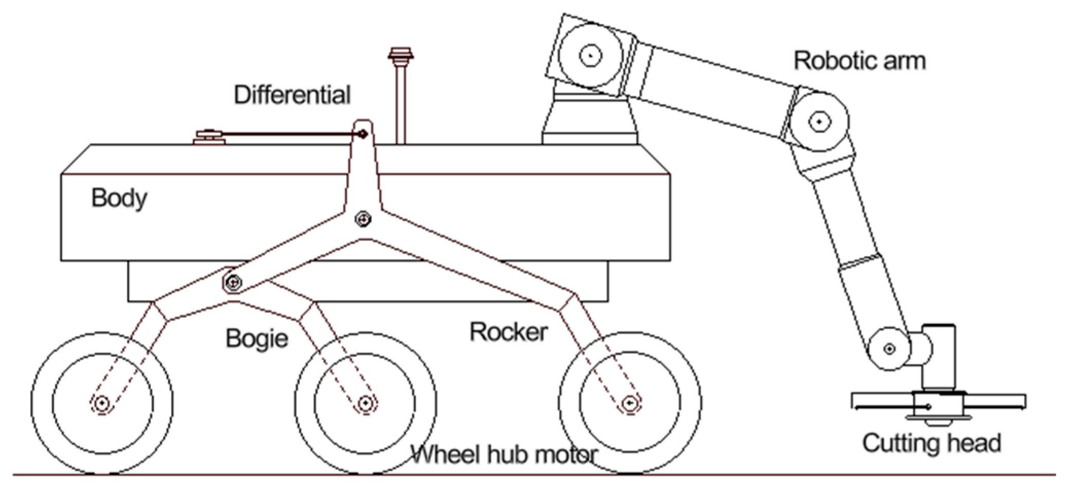
The proposed mobile robot is schematically represented in
Figure 1; the body dimensions are 1000 × 600 × 300 mm, which should be adequate to operate in quite restricted areas; it supports a robotic arm, with an outreach of about 850 mm, whose end effector is a cutting head.
The choice of the size of the wheels and of the suspension elements can be made by adopting optimization algorithms that consider the geometric characteristics of the obstacles that the rover must overcome, as reported in [
24].
The geometric characteristics of the rover were chosen considering that the diameter of the wheels should be approximately equal to one-half the height of the obstacles to be overcome [
24,
25,
26]. Considering a 500 mm high obstacle, the wheel could have the dimensions of a commercial wheel hub motor: a wheel 245 mm in diameter and 79 mm wide with a tire pattern for off-road use.
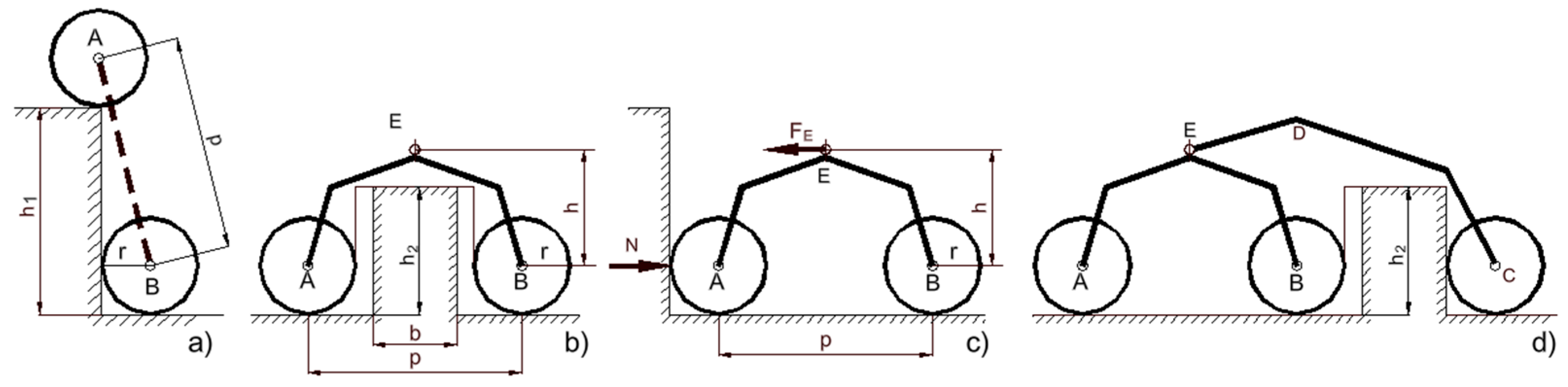
Once the height
h0 of the obstacle to be overcome has been defined, the length of the bogie wheelbase (
p) can be chosen such that, when the first wheel is on the obstacle, the second one is just in contact with it. With reference to
Figure 2a,
The bogie wheelbase was chosen to be 520 mm. The height and shape of the bogie depend on the geometry of the “box” obstacle to be overcome (
Figure 2b). The bogie height (
h2) represents the perpendicular distance between the two parallel forces, F
E and N, that generate the moment that opposes the rotation of the bogie in the initial phase of climbing the obstacle (
Figure 2c) exerted by the rocker and the obstacle, respectively. Attention must be paid to the shape of the rocker to avoid interference with the box obstacle (
Figure 2d).
2.2. Robotic Arm and Cutting Head
The cutting head of the electric brush cutter is mounted at the end of a robotic arm; as reference, the Universal Robots UR5 [
27] manipulator was chosen. It is characterized by a mass of 20 kg, an outreach of 850 mm, and a payload of 5 kg, which is in accordance with the mass of the chosen cutting head (about 2 kg). The energy consumption required by the cutting head depends on the type of vegetation to be cut; its rotation speed is adjustable in the range 6000–9000 rpm; low values are adopted for normal cut operation while higher ones are used to cut denser vegetation. The manipulator motors must also provide a reaction torque to the gyroscopic torques that arise from the simultaneous rotation of the cutting head rotor around two orthogonal axes. Considering that each link can rotate at the maximum speed rotation of 30 rpm, and have a rotor of about 1.25∙10
3 kgm
2, the maximum gyroscopic torque can reach values of about 3–4 Nm.
Inertial forces due to acceleration or deceleration of the rover and of the arm can be neglected, since the system is designed to move at low speed during the cutting operations.
The reaction forces generated during the cutting phase depend on the peripheral velocity of the rotating disc and on the power absorbed by the cutting head (FC = P/v). The gyroscopic effects, which oppose rotational movement of the brush cutter, depend on its moment of inertia and on the angular velocity of precession. These forces and moments must be considered when evaluating the required load and torque capacity of the robotic arm.
The estimated values for the forces and torques acting at the end of the robotic arm are provided in
Table 1. They were defined considering a 500 W cutting head placed 0.5 m from the terminal flange of the arm, with a 2 kg mass; the moment of inertia of its rotating disc was considered equal to 0.0225 kgm
2, its rotating velocity equal to 7600 rpm, and a precession rotating velocity equal to 0.1 rad/s.
2.3. Energy Consumption
The operation of the device involves an average power of about 2500 W with peaks of about 3600 W. It must be considered that a manual brush cutter with a power of approximately 2 kW can cut shrubs with diameters up to about 2 cm, especially if equipped with disc or toothed blades. However, considering that more frequent cutting prevents the vegetation from developing a significant diameter or woody consistency, and that the focus is on the management of the cutting head, a 500 W brush cutter was selected to reduce energy consumption and increase system autonomy. The average power required by the robotic arm is about 200 W with peaks of 570 W; each of the six wheels of the mobile robot has a 500 W electric motor but the overall power used is equal to about 2000 W (it is considered that, due to the unfavourable ground conditions, two wheels are not able to exert a traction action and that the rover can still move forward with the other four wheels). For the other devices (control system, sensors, etc.) a power of about 30 W is estimated.
It is planned to use a LiFePO4 battery, with a capacity of 90 Ah, nominal voltage of 48 V, and total energy: C = 90 × 48 = 4320 Wh.
Considering a battery efficiency η of 95%, the autonomy of the rover (a = (C/P)η) could approximately range between 2 and 1 h for a required power ranging between 2000 and 3500 W.
The typical energy density δ of LiFePO4 batteries is 95 Wh/kg; therefore, the estimated mass of the battery is as follows: m = C/δ = 45 kg.
2.4. Longitudinal and Lateral Stability
The geometry and the distribution of the masses ensure a good stability of the mobile robot; after some rough evaluations, the following masses are considered for the main components: about 80 kg for the body (chassis, batteries, control system, etc.), 14 kg for the kinematic suspension, about 34 kg for the motorized wheels, 20 kg for the robotic arm, and 2 kg for the cutting head. The total mass is approximately 150 kg.
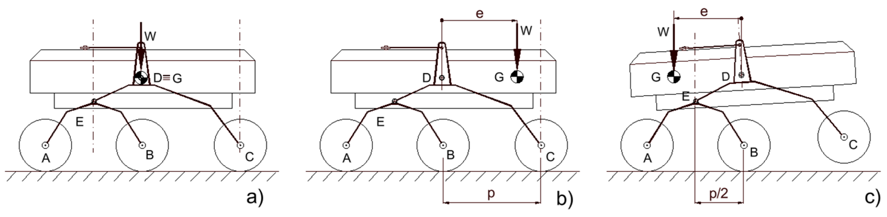
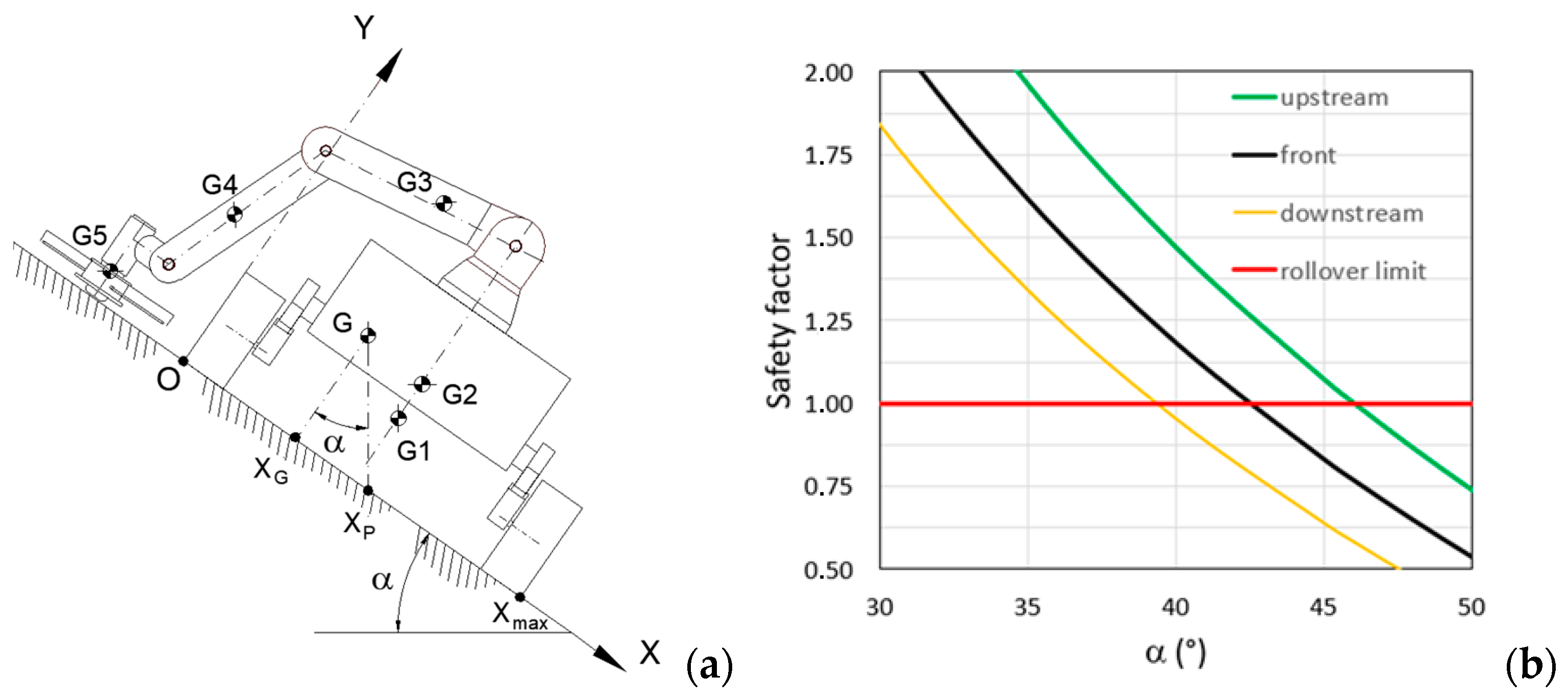
The robotic arm configuration causes a shift in the centre of mass G of the rover and a different load distribution between the wheels (
Figure 3). With reference to the longitudinal shift, indicating with
e the eccentricity of weight
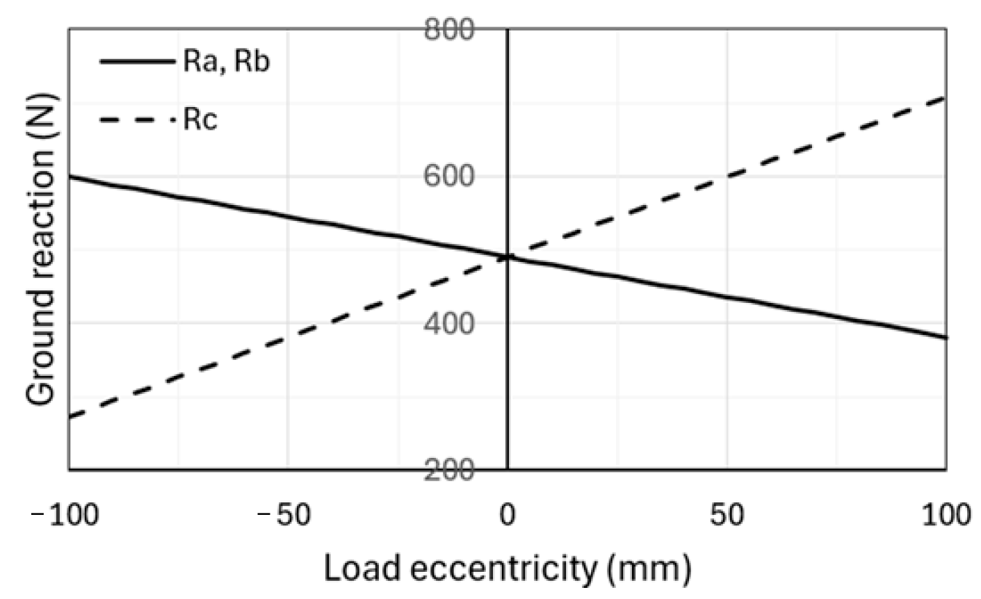
W, with respect to point D, in case of flat and horizontal ground, the vertical ground reactions are
If
W is the total load, these expressions refer to the wheel pairs of the same axle. In
Figure 4, the ground reactions are plotted versus the eccentricity. If the G position is shifted to the rocker side (
Figure 3b), higher load acts on the rocker wheels while the remaining load is equally distributed among the wheels of the bogie; in this case, the eccentricity must be lower than the wheelbase (
p) to avoid overturning around hinge C. If the centre of mass is shifted to the bogie side (
Figure 3c), the eccentricity must be lower than one-half the wheelbase (
p/2) to avoid overturning around hinge E that connects the rocker and bogie. For this reason, it is preferable to locate the robotic arm on the rocker side.
Considering the mass of the mobile platform and that of the robotic arm, as the configuration of the latter varies, the maximum displacement of the centre of gravity of the entire rover is approximately 80 mm. The eccentricity of the weight could be used to increase the longitudinal or lateral stability of the rover, in case of sloping terrain; to reduce the load on a pair of wheels to allow the rover to overcome an obstacle more easily; and to increase the load on the wheels with greater grip to increase the overall traction force.
The lateral stability is evaluated on a transversal sloped ground, considering the robotic arm operating both frontally and laterally to the rover chassis. With the data reported in
Table 2, the overturning safety factor, i.e., the ratio of stabilizing to overturning moments, is represented in
Figure 5 as a function of the ground transversal inclination α. The analysis reveals that the rover can handle slopes that are approximately 4° steeper if the cutting head operates upstream rather than in front of the chassis. Under this condition, it must be evaluated if lateral slip may occur before lateral overturning.
3. Load on Wheels
If all the wheels of the rover can rest on the ground, the ratio between the maximum traction and load acting on each wheel can be assumed to be constant; in this way, the rover can exert the maximum traction force and can advance with relatively low grip. The load acting on each wheel depends on the configuration that the rover assumes due to the irregularity of the soil.
Some theoretical and experimental evaluations have been conducted by adopting the geometric characteristics of the Bogie Runt Rover™ [
28] equipped with rocker–bogie suspension and six wheels. The suspension link is made of ABS (acrilonitrile-butadiene-stirene); its geometric characteristics are indicated in
Table 3. The rover is equipped with six independent driving wheels whose diameter and width are 65 mm and 25 mm, respectively; each electric motor provides a stall torque of 78.4 Nmm with a current of 250 mA, 6 V; the maximum rotation speed is 140 rpm; the mass of the rover is equal to about 0.870 kg.
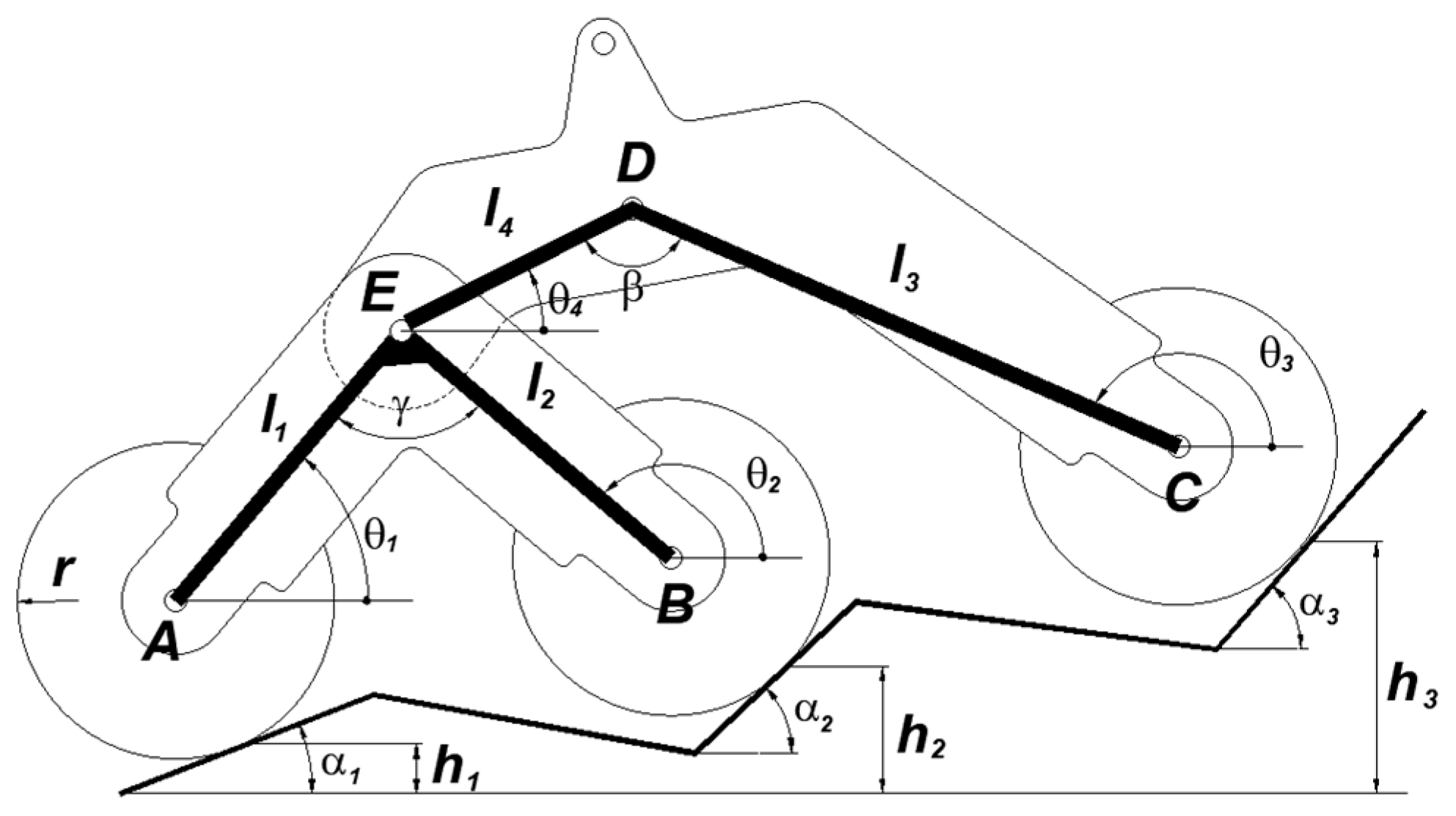
Referring to the planar scheme for a semi-suspension (
Figure 6), if all the wheels are at the same level, the load applied at point D is equally distributed between the three wheels. For generic soil profiles, to define the load on each wheel, it is first necessary to solve the kinematic analysis [
29] to define the suspension pose in terms of the angles
θi between the axis of each link and the horizontal direction. If the soil profile is defined by the height
of the wheel–soil contact point and by the soil inclination,
, at the same point, the
angles can be obtained from the following equations:
with
where
and
are the fixed angle of the rocker and bogie, respectively, while
is the relative rotation between the rocker and bogie.
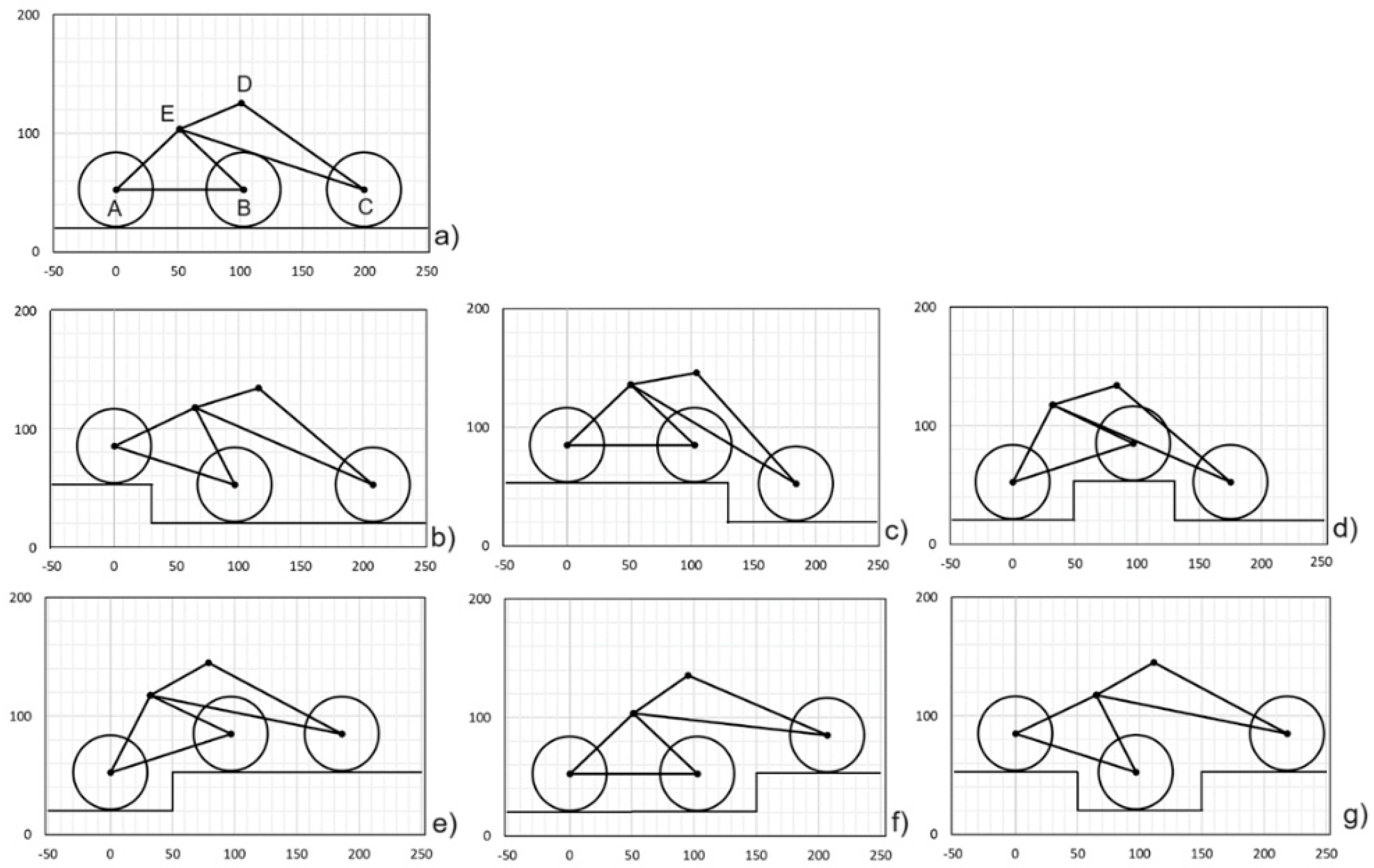
A kinematic analysis was developed for some soil profiles (
Figure 7) and the results are reported in
Table 4. For each case, the table also reports the soil reactions due to the vertical load of 300 N, acting at point D. This load, although large enough for the considered rover, leads to a reaction on each wheel equal to 100 N if all the wheels are on flat and horizontal soil (
Figure 3a) allowing us, for the other poses, to easily evaluate the percentage variation of the load. The table shows that, by shifting the wheels up or down by a quantity equal to the wheel radius, the soil reactions can undergo variations of up to 40%. The corresponding maximum traction force undergoes the same variations.
4. Grip Condition Evaluation
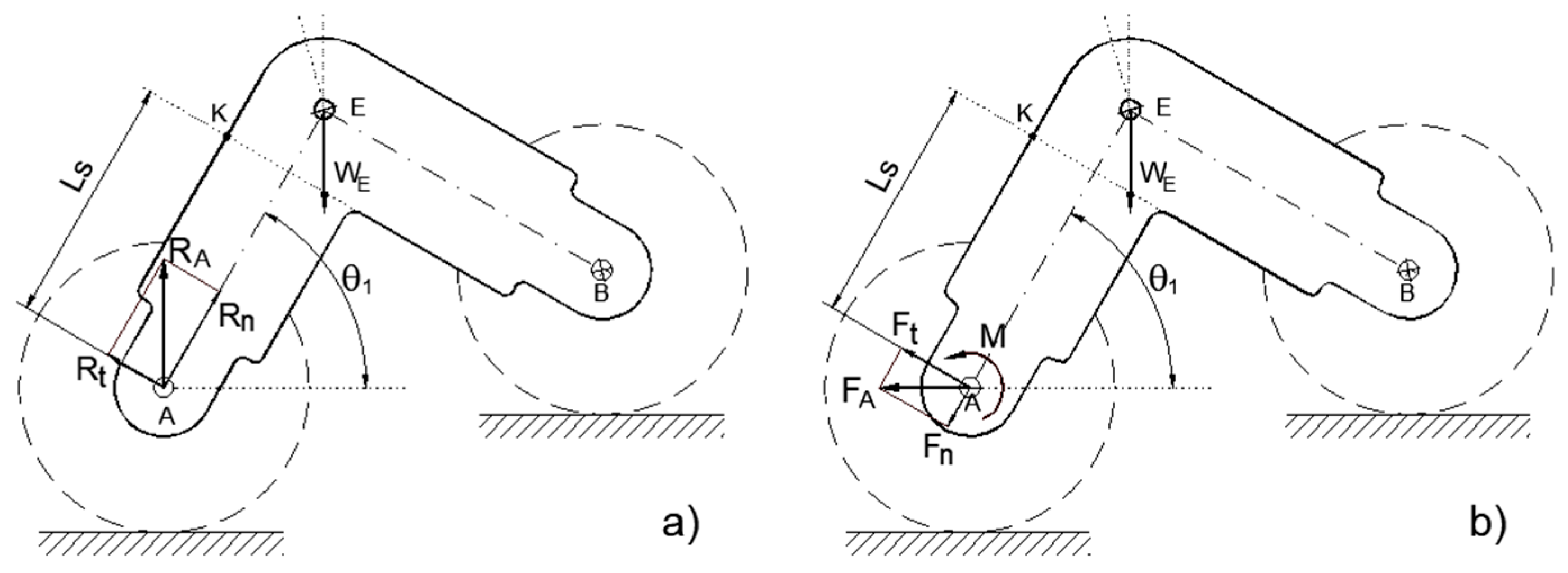
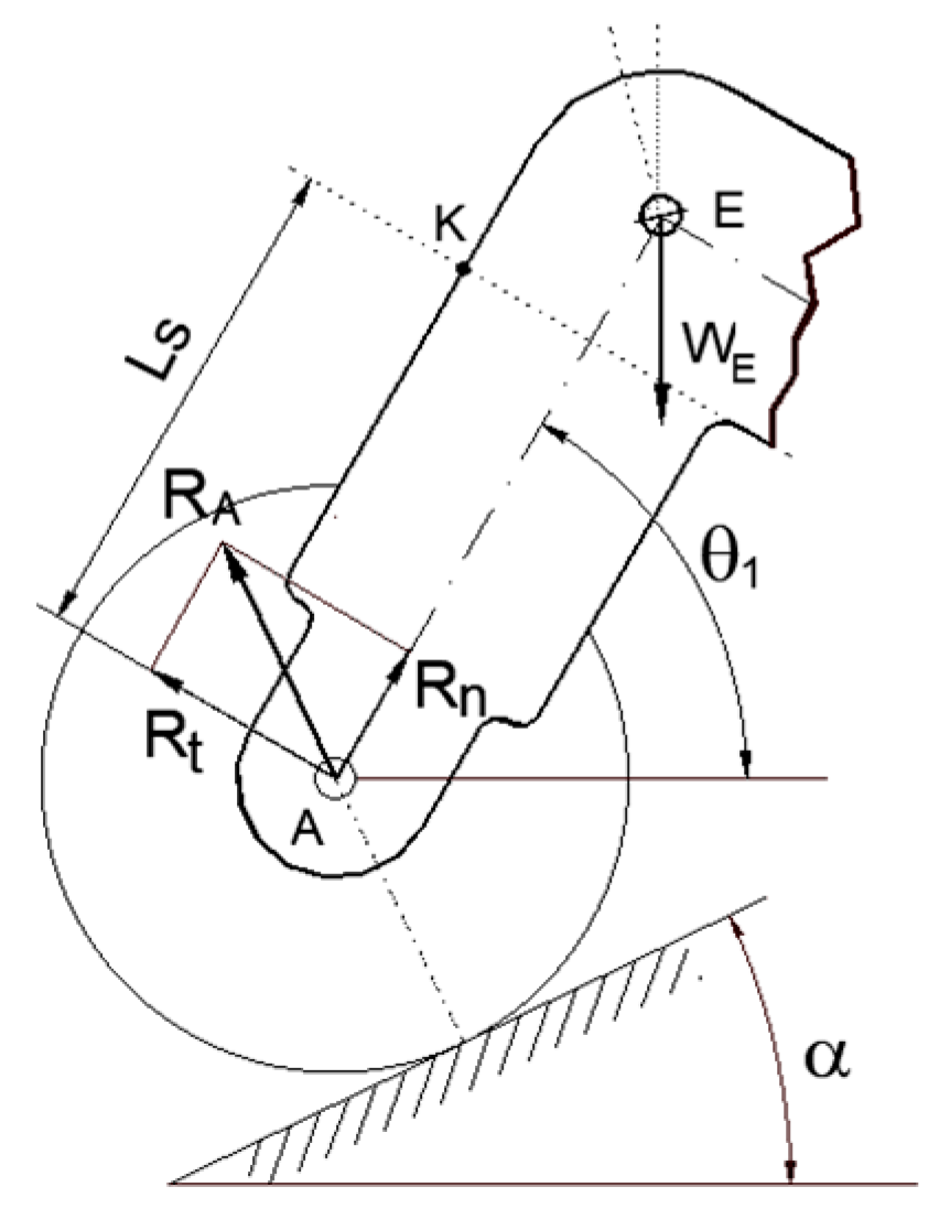
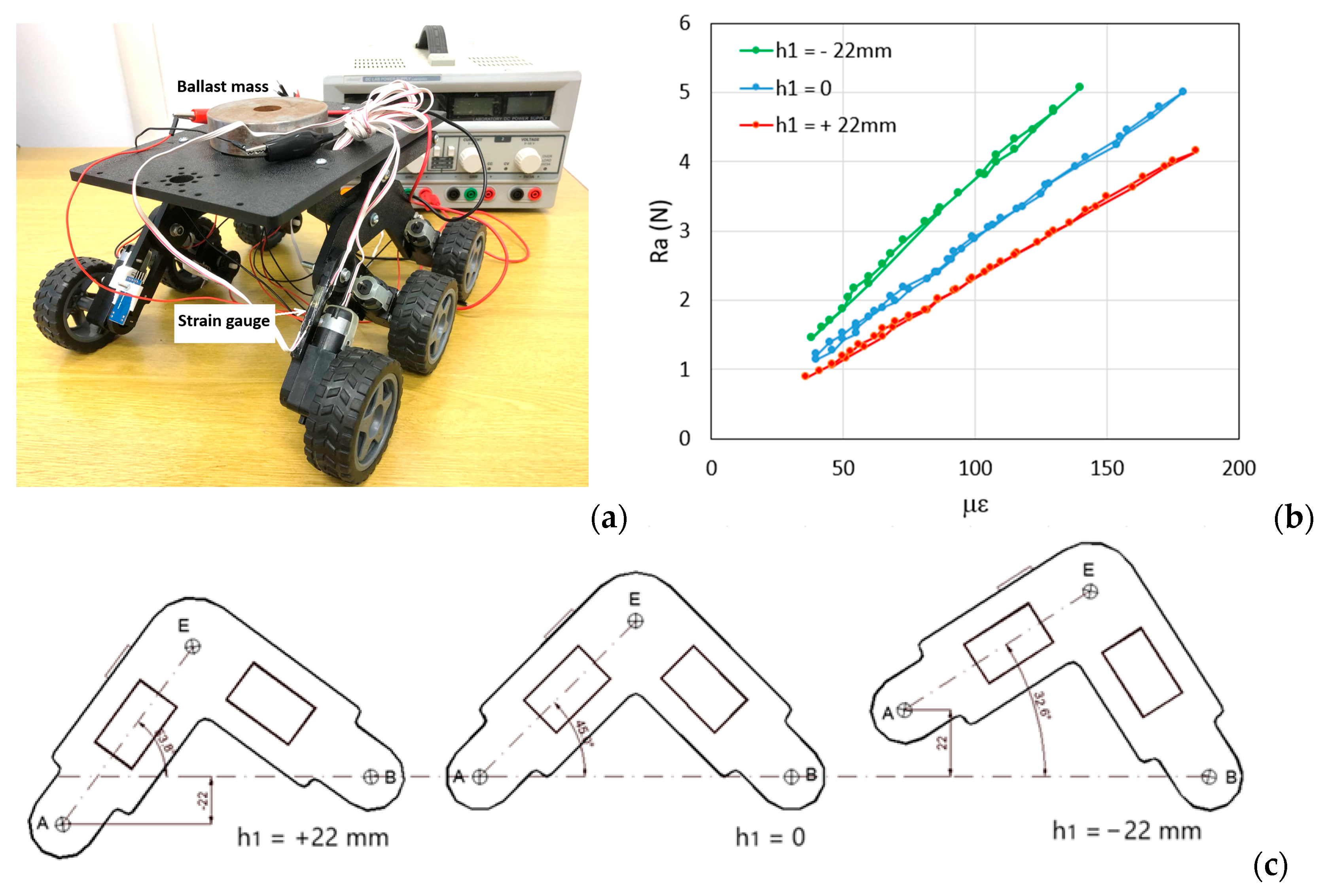
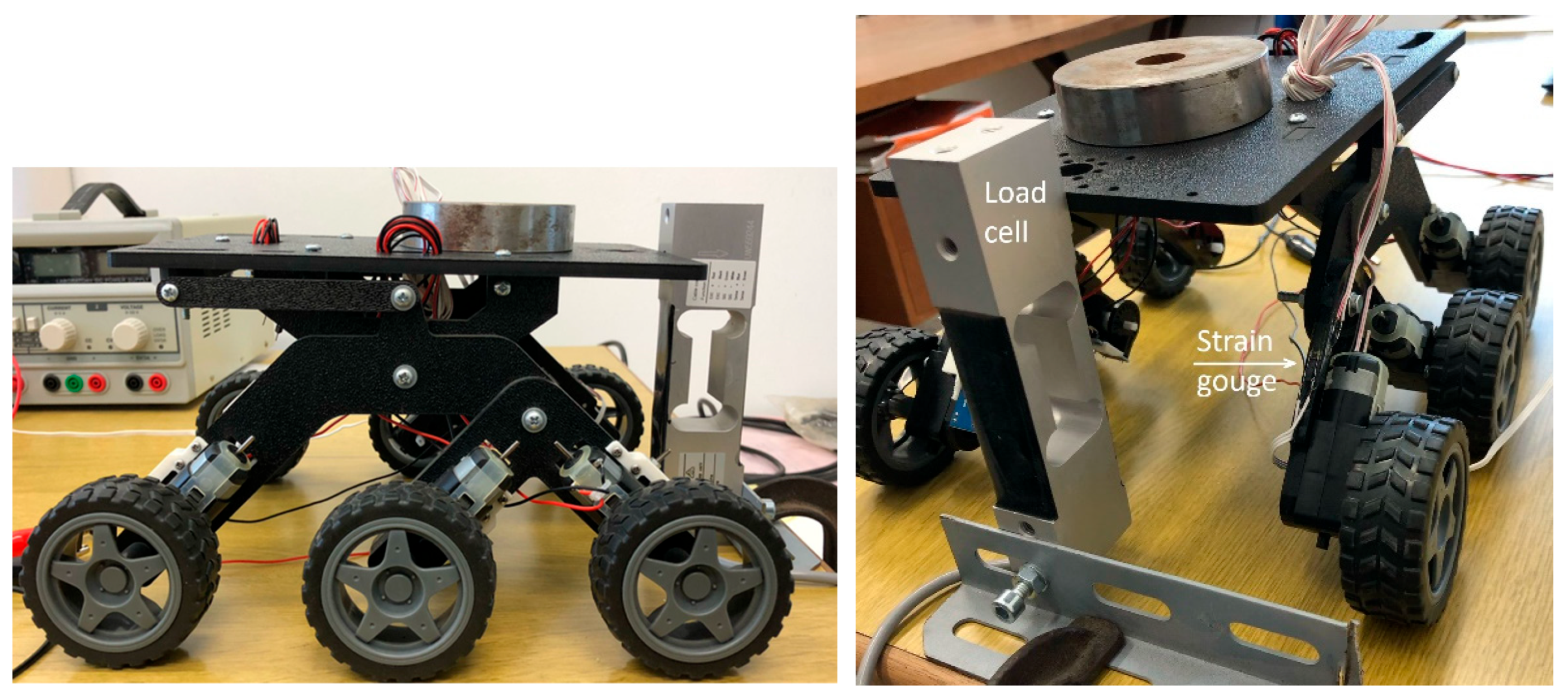
To develop a slip prevention system, which uses the front wheels of the bogie as tactile sensors, the vertical load acting on the front driving wheels must be estimated. Since the rover can move in both directions (rocker forward or bogie forward) the deflection measurement must be performed on the outer suspension links. Below, the results of some tests regarding the deflection of the outer bogie link are reported. This deformation depends on the ground reaction acting on wheel A and on the bogie inclination that can assume non-negligible values. In case of flat and horizontal soil (
Figure 8), the vertical reaction R
A can be decomposed according to the direction of the arm axis and its normal. The normal stress at point
k of the bogie arm, where it is assumed to place a strain gauge, is
In Equation (6), the stress contribution, due to the eccentricity of the load with respect to the plane of the bogie arm which induces bending, and a torsional moment, has been neglected. It can be considered with sufficient approximation that the strain gauge placed on the back of the bogie does not detect this deformation (the average value is zero) or that, in any case, it does not significantly influence the deformation detected by the strain gauge.
The negative sign is due to the compressive stress. As a result,
, with E being the Young modulus and
the strain. Therefore,
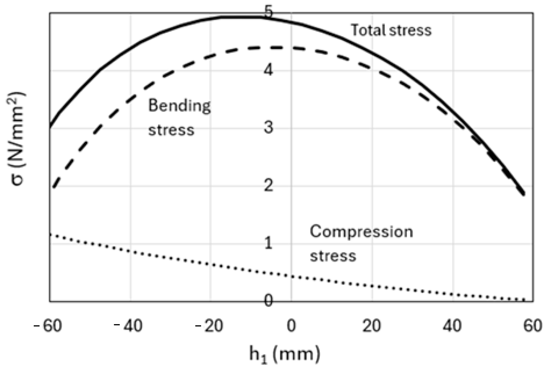
With reference to the cross-section of the front arm of the bogie (rectangular 5 × 32 mm), considering a load of 300 N applied at point D of the suspension, the moduli of the compressive and bending stresses at point K (Ls = 53 mm), for different values of the height h1 of the front wheel axle, keeping the positions of the other wheels unchanged, are reported in
Figure 9. The diagram shows the easily predictable result that the compressive stress is zero if the front arm of the bogie is horizontal while the bending stress is zero if the same arm is vertical; the value chosen for Ls makes the compressive stress less than the bending stress.
Once the load R
A acting on the wheel, in the case of zero driving moment, has been identified, it is possible to increase the driving torque of wheel A. Due to the driving torque M = Sr, with S being the traction force and r the wheel radius, the front arm is subjected to an additional moment and, therefore, the normal stress at point K is
The stress and strain at point K increase (in modulus) with the driving torque until the wheel begins to slip. Slippage produces a reduction in strain that can be detected to identify the maximum value of the tractive force S
max from which slippage occurs; the ratio S
max/R
A represents the grip coefficient μ. The maximum thrust is:
The stress in the trolley arm varies if the ground in the contact area is not level. (
Figure 10). The local slope of the ground could be measured by LIDAR, often installed on such vehicles, which can detect this feature even in the presence of vegetation. In the case of ground inclined at an angle α
1, the stress in the front arm of the bogie is


