Article

Performance Prediction of Outer Rotor PMSM Considering 3-D Flux Coefficient Using Equivalent 2-D FEA

1
Department of Automotive Engineering (Automotive-Computer Convergence), Hanyang University, Seoul 04763, Republic of Korea
2
Vehicle Electrification R & D Center, Korea Automotive Technology Institute, Daegu 43011, Republic of Korea
3
Department of Automotive Engineering, Yeungnam University, Gyeongsan 38541, Republic of Korea
4
Power Electronics Lab, H & A R & D Center, LG Electronics, Seoul 08592, Republic of Korea
*
Author to whom correspondence should be addressed.
Machines 2025, 13(8), 692; https://doi.org/10.3390/machines13080692
Submission received: 18 June 2025 / Revised: 3 August 2025 / Accepted: 5 August 2025 / Published: 6 August 2025

Abstract

In this article, we propose an equivalent 2-D finite element analysis (FEA) process considering the 3-D flux of an outer rotor permanent magnet synchronous motor (PMSM). In the motor, 3-D flux such as axial leakage flux (ALF) and overhang fringing flux (OFF) are influenced based on design variables. Three-dimensional FEA is required to consider the components of 3-D flux. However, 3-D FEA is inefficient to use during the design process because of time-consuming. Therefore, we propose an equivalent FEA that considers the 3-D flux. First, the effects of ALF and OFF according to design variables such as rotor inner and outer diameter, stack length, and overhang length. Second, the 3-D flux is converted into a coefficient. Finally, it is applied to 2-D FEA. Using the proposed process, motor performance considering 3-D flux can be quickly predicted. The proposed performance prediction process is verified through simulation and experiment.

1. Introduction

The permanent magnet synchronous motor (PMSM) is widely used in home appliances (HA), such as air conditioners and fans, to improve energy efficiency [1,2,3,4]. To achieve high power density, rare-earth magnets are commonly employed in PMSMs. However, the cost of rare-earth magnets continues to rise due to limited production areas and supply instability. As a result, researchers in the HA field are actively exploring the development of relatively low-cost, rare-earth-free motors to enhance price competitiveness. Non-rare-earth magnets exhibit weaker magnetic strength, and consequently, rare-earth-free motors suffer significant performance degradation due to leakage flux. One approach to mitigate this performance degradation is to apply a rotor overhang structure. The rotor overhang structure effectively enhances the air gap flux and power density by leveraging fringing flux. To accurately account for axial leakage flux (ALF) and overhang fringing flux (OFF), 3-D finite element analysis (FEA) is required. However, 3-D FEA is computationally intensive and inefficient for use during the early stages of the design process. To address this, previous works have proposed equivalent magnetic circuit (EMC) and empirical scaling approaches [5,6,7,8]. In [5,6], the leakage flux path was arbitrarily assumed to construct the EMC model. In [7], a mathematical formulation was applied for the design of a magnetic gear. Reference [8] introduced a 2-D lumped magnetic circuit model to efficiently analyze the overhang effects in surface-mounted permanent magnet machines, and its accuracy was validated through 3-D FEA and experimental results under various design conditions. However, these methods often rely on simplified assumptions or general coefficients, which may not fully capture the interaction between key design parameters and 3-D flux effects. Although EMC enables rapid performance estimation, the required modeling time depends on the desired level of accuracy. Furthermore, since the flux path is difficult to model precisely, several assumptions are often introduced, which may lead to inaccuracies in predicting the impact of ALF. EMC has the advantage of quickly predicting the motor performance, but the time required for modeling depends on the precision of the results desired. Additionally, since it is difficult to consider the path accurately, assumptions are made. These assumptions may lead to errors in predicting the impact of ALF. Previous studies [9,10,11,12,13] did not consider ALF generated by the motor, while [14] proposed an ALF path for a surface-mounted PMSM and applied it to 2-D FEA. Various approaches have been explored to improve motor performance. In [15], leakage flux was entirely eliminated using plastic injection molding. In [16], the leakage flux path was reduced through alternating multi-core stacking. In [17], motor performance was improved by applying a combination of rotor overhang and alternating stacking. Existing studies have focused on the design and analysis of inner rotor surface-mounted PMSMs and spoke-type PMSMs. However, there are a few analysis methods that simultaneously consider ALF and OFF in relation to design variables, and some studies have neglected them.
In this study, we propose a novel performance prediction method for outer rotor PMSMs that integrates 3-D flux effects (ALF and OFF) into an equivalent 2-D FEA framework. The method generates flux correction coefficients based on design variables, enabling accurate and efficient prediction of no-load back electromotive force (BEMF). This work differs from existing EMC and empirical approaches by incorporating 3-D flux dependency into a 2-D analysis structure through systematic coefficient extraction and design variable linkage. The proposed method allows for rapid prediction of motor performance while accounting for ALF and OFF, considering key design parameters such as rotor inner and outer diameters and stator/rotor stack lengths. First, the effect of ALF and OFF on outer rotor PMSM performance, according to changes in design variables, is investigated by comparing the results of 2-D and 3-D FEA. Through this comparison, design variables affecting ALF and OFF are identified. Second, this study introduces the performance prediction process using equivalent 2-D FEA. To confirm the accuracy of the proposed method, the results are compared with 3-D FEA results. Finally, the effectiveness of the proposed method is validated through testing on a fabricated prototype of the outer rotor PMSM.

2. Design Variables Affecting 3-D Flux

In this section, design variables influencing ALF and OFF are identified based on their relevance to the motor’s electromagnetic characteristics. The selected variables, including the inner and outer diameters of the rotor and the stacking lengths of the rotor and stator, serve as fundamental parameters in determining the motor geometry and flux path [18,19]. Subsequently, these variables are used to define the geometry ratio and the overhang ratio, which quantitatively represent the structural configuration affecting ALF and OFF, respectively. This formulation provides a basis for systematically analyzing the impact of design variations on 3-D flux phenomena and motor performance.

2.1. Axial Leakage Flux (ALF)

ALF is caused by the difference in magnetic vector potential between rotor cores. Figure 1a illustrates the structure of the outer rotor, where the rotor cores are separated by permanent magnets, creating a significant magnetic potential difference between adjacent rotor cores. Since permanent magnets have a permeability similar to air, magnetic flux tends to leak along the axial path between rotor cores. As a result, axial leakage flux is generated through the motor’s axial air path, as shown in Figure 1b, between adjacent rotor cores. Such leakage flux does not pass through the air gap, thereby reducing the effective air gap flux, which in turn leads to degradation of motor performance. In particular, the reduction in effective flux due to ALF results in a decrease in one of the key performance indicators of the motor: the no-load BEMF. The total magnetic flux passing through the air gap is a combination of the effective air gap flux and the leakage flux caused by ALF. The relationship can be expressed as follows:
Φ g = Φ total Φ alf
where Φg is the effective magnetic flux through the air gap, Φtotal is the total magnetic flux passing through the air gap, and Φalf is the leakage flux due to ALF. The decrease in effective magnetic flux caused by ALF results in reduced BEMF, which is given as follows:
E = N d Φ d t
where E is the BEMF, N is the number of turns in the coil. When ALF is present, the BEMF is reduced because the effective flux is smaller, which leads to the following:
E = N d ( Φ t o t a l Φ a l f ) d t
The increase in BEMF due to ALF can be quantified as follows:
Δ E a l f = N d Φ a l f d t
where ΔEalf is the reduced BEMF caused by ALF.
This reduction in BEMF directly results in a decrease in output power, which is given as follows:
Δ P = Δ E × I = N d Φ a l f d t × I
where ΔP is the decrease in output power, and I is the current supplied to the motor.
In conclusion, ALF, induced by the magnetic vector potential difference between adjacent rotor cores, leads to a reduction in the effective air gap flux. This diminished flux subsequently results in a decrease in both the BEMF and the output power of the motor.

2.2. Overhang Fringing Flux (OFF)

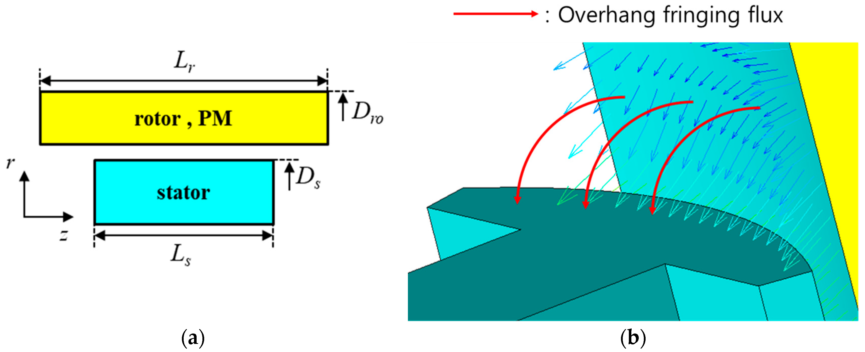
The overhang refers to a structural configuration in which the rotor stack length exceeds that of the stator, as illustrated in Figure 2a. This configuration contributes to an increase in magnetic flux, as the extended use of permanent magnets leads to enhanced magnetic field generation. Consequently, the motor performance is improved. Figure 2b presents the additional magnetic flux path that is formed due to the presence of the overhang. The rotor overhang structure extends the magnetic flux path, enabling a more uniform and efficient distribution of the magnetic field. In particular, the increased cross-sectional area of the flux path and the effective utilization of fringing flux contribute to an enhancement in the air gap flux density, which leads to improvements in both BEMF and output torque. When the rotor overhang is applied and the effect of ALF is not considered, the magnetic flux in the air gap increases. This can be expressed mathematically as follows:
Φ t o t a l = Φ g + Φ o v h
where Φtotal is the total magnetic flux passing through the air gap, Φg is the magnetic flux when the rotor overhang is not applied, and Φovh is the fringing flux caused by the rotor overhang. Specifically, when an overhang is introduced, the magnetic flux is enhanced, which consequently increases the air gap flux. In the presence of OFF, the BEMF increases as the total magnetic flux is enhanced, resulting in the following:
E = N d Φ d t = N d ( Φ g + Φ o v h ) d t
The increase in BEMF due to OFF can be quantified as follows:
Δ E o v h = N d Φ o v h d t
where ΔEovh is the increased BEMF caused by OFF.
This increase in BEMF directly results in an increase in output power, which is described as follows:
Δ P i n c = Δ E o v h × I = N d Φ o f f d t × I
where ΔP is the increase in output power.
In conclusion, OFF, which arises from the additional magnetic flux generated by the rotor overhang, contributes to an increase in the effective air gap flux. This enhanced flux subsequently leads to an increase in both the BEMF and the output power of the motor.

2.3. Influence of Design Variables on 3-D Flux Effects

The design variables of PMSM significantly influence its electromagnetic characteristics. Assuming a constant outer diameter of the rotor in the outer rotor motor, a decrease in the inner rotor diameter leads to an increase in the rotor’s saturation. As the stack length increases, the magnetic flux flows more efficiently through the air gap, resulting in a higher BEMF and improved output power. However, physical space limitations and manufacturing costs impose constraints. Table 1 shows the shape, specifications, and design range of the PMSM. The outer diameter of the rotor, inner diameter of the stator, pole arc of the permanent magnets, and air gap length are set as constants. This article investigates the design variables that influence ALF and OFF.
ALF is influenced by the ratio of the rotor’s inner and outer diameters as well as the stack length, assuming the motor volume remains constant. The design variables affecting ALF are expressed as follows:
G R = L s t k D r o D r i
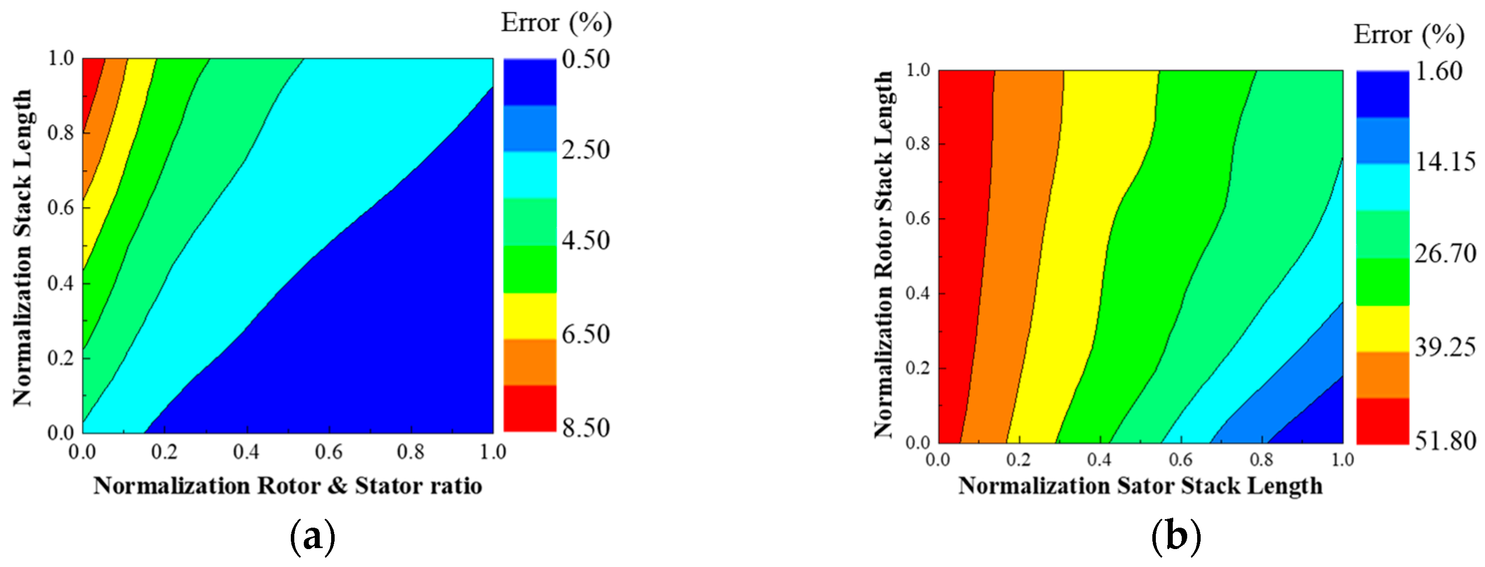
where GR is the geometry ratio, Lstk is the stack length of the motor, Dro is the rotor outer diameter, and Dri is the rotor inner diameter. To evaluate the impact of ALF based on the geometry ratio, 2-D and 3-D finite element analysis (FEA) were performed. Figure 3a compares the fundamental BEMF values obtained from 2-D and 3-D FEA simulations. It is evident that as the stack length decreases and the difference between the inner and outer rotor diameters increases, the influence of ALF becomes significant and cannot be neglected.
OFF is influenced by the stack lengths of both the stator and the rotor. The design variables affecting OFF are expressed as follows:
O R = L r L s
where OR is the overhang ratio, Lr is the rotor stack length, and Ls is the stator stack length. Here, the overhang ratio is always greater than or equal to 1.
To investigate the impact of OFF based on the overhang ratio, 2-D and 3-D FEA were conducted. Figure 3b presents the comparison of the fundamental BEMF values obtained from 2-D and 3-D FEA for varying overhang ratios. The results show that as the overhang ratio increases, the influence of OFF becomes more pronounced and cannot be ignored. In conclusion, an analysis that considers 3-D flux, such as ALF and OFF, is essential for accurate performance prediction and optimization of PMSM.

3. Performance Prediction Method Considering 3-D Flux

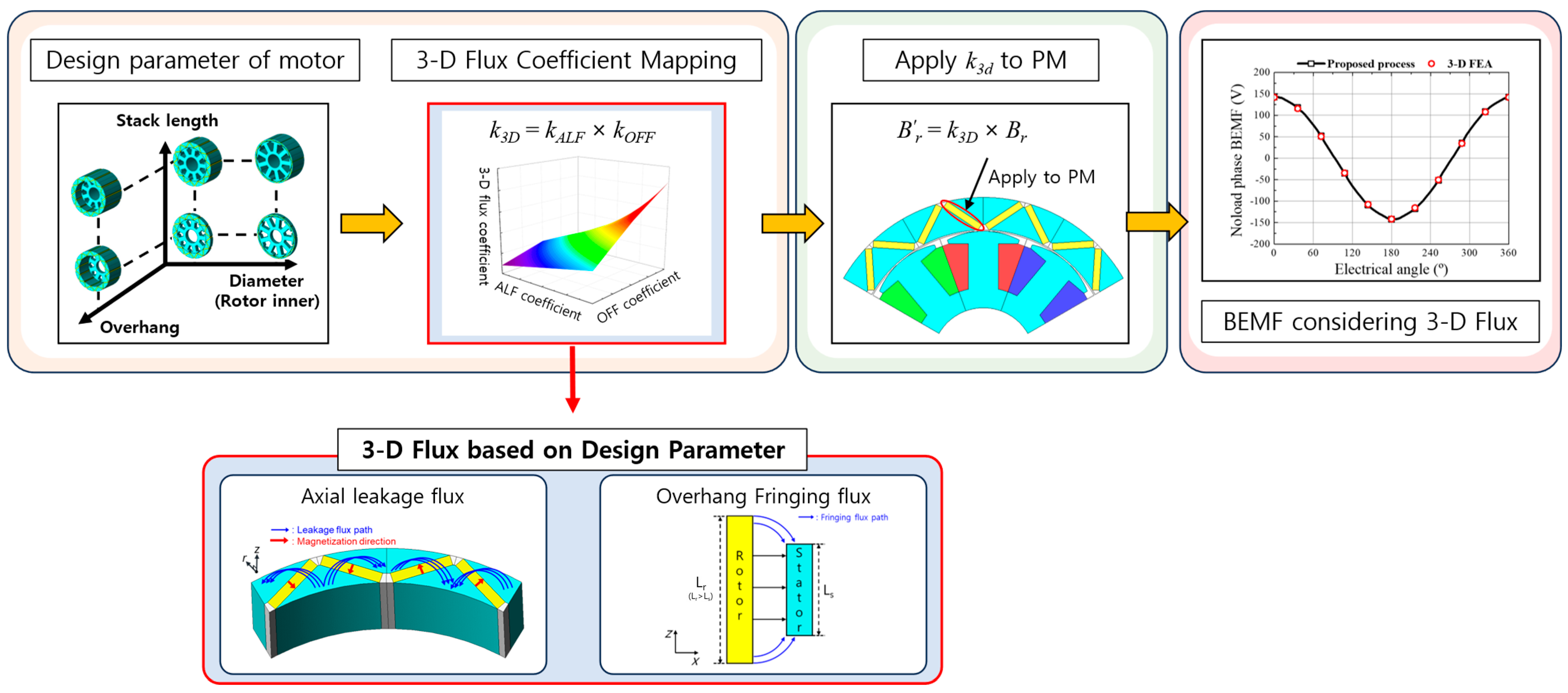
This section presents the proposed method for integrating the effects of 3-D flux into the motor performance prediction process. The proposed method is divided into three key stages, each systematically analyzing the impact of 3-D flux on motor performance and offering an efficient approach to predicting these effects. The proposed process using the 3-D flux coefficient is shown in Figure 4.
First, the effects of motor design variables on 3-D flux, specifically ALF and OFF, are investigated. To achieve this, coefficients for ALF and OFF are calculated to quantitatively analyze how these fluxes are reflected in motor performance. To determine the correction coefficients for ALF and OFF, at least one reference 3-D FEA simulation is required. The coefficients are extracted by comparing 3-D and 2-D no-load BEMF results as follows:
e a x l = E 3 D   w / o     o v h ,   e o v h = E 3 D   w i t h     o v h
where eaxl is the result of 3-D FEA where the fundamental component of the BEMF is calculated considering ALF, E3D(w/o ovh) is 3-D FEA without rotor overhang, eovh is the result of 3-D FEA where the fundamental component of the BEMF is calculated considering rotor overhang, and E3D(with ovh) is 3-D FEA considering rotor overhang.
The coefficients of ALF and OFF are expressed as follows:
k A L F = e a x l e n o n a x l ,   k O F F = e o v h e n o n o v h
where kALF is the coefficient of ALF, enon−axl is the result of 2-D FEA where the fundamental component of the BEMF is calculated without considering ALF. kOFF is the coefficient of OFF and enon−ovh is the result of 2-D FEA where the fundamental component of the BEMF is calculated without considering rotor overhang.
In the second stage, the ALF and OFF coefficients, calculated in the previous step, are utilized to derive the 3-D flux coefficient. Given that the ALF and OFF coefficients operate independently, the 3-D flux coefficient is obtained by multiplying these two coefficients. The 3-D flux coefficient significantly influences the total magnetic flux and is essential for accurately predicting motor performance. The 3-D flux coefficient is expressed as follows:
k 3 D = k A L F × k O F F
where k3D is the coefficient of the 3-D flux coefficient.
Then, the ALF coefficient and OFF coefficient are utilized to map the 3-D flux coefficient. Next, the 3-D flux coefficient is applied to the residual induction of the permanent magnet, and 2-D FEA is conducted. The new residual induction is expressed as follows:
B r = k 3 D × B r
where B r is the residual induction considering the 3-D flux coefficient, and Br is the residual induction generally used in 2-D FEA. In this case, when residual induction considering 3-D flux is used, this is referred to as equivalent 2-D FEA. Finally, the results of equivalent 2-D FEA and 3-D FEA are compared.

4. Simulation and Experimental Verification

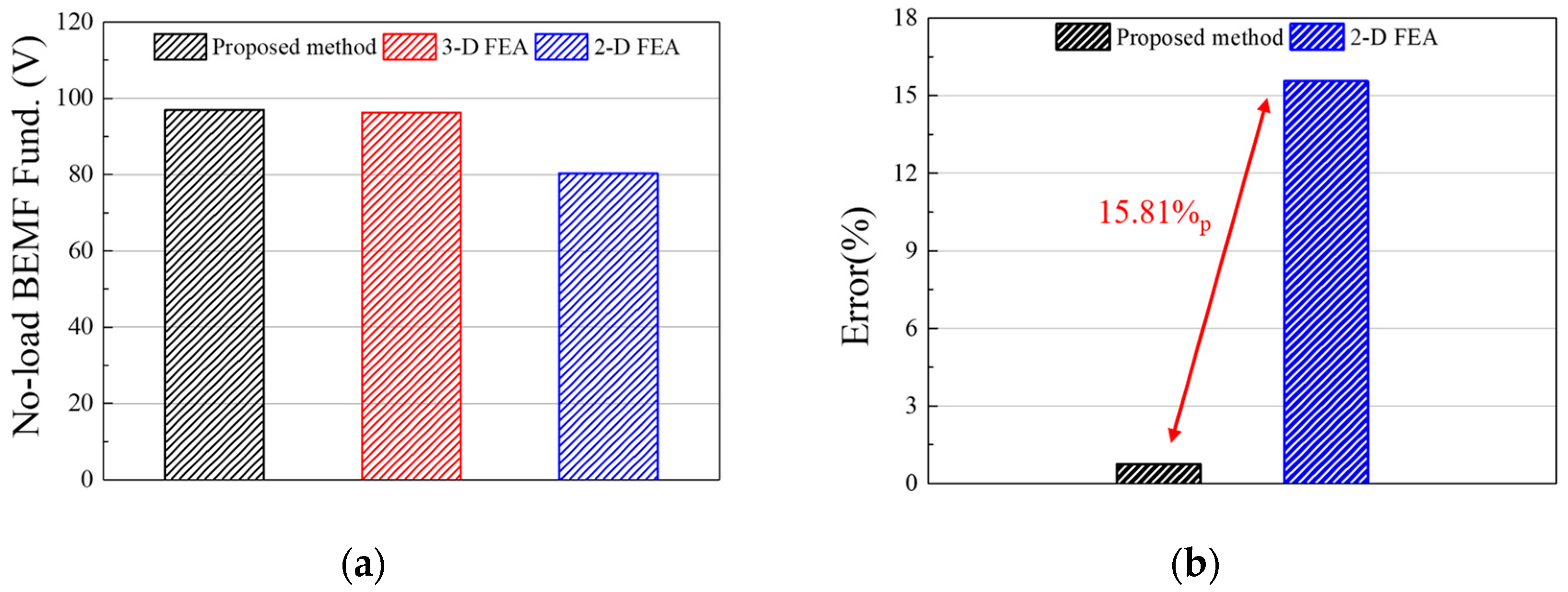
To verify the proposed method, the amplitude of the no-load BEMF fundamental is compared through simulation. Figure 5a presents a comparison of the no-load BEMF fundamental components obtained from the proposed method and the 2-D/3-D FEA approaches. When the 3-D FEA results are regarded as reference values, the proposed method yields predictions that closely align with the reference, whereas the 2-D FEA shows significant deviations. Figure 5b quantifies the relative error associated with each method. The 2-D FEA, which does not account for ALF and OFF, results in an error exceeding 15%. In contrast, the proposed method maintains an error below 1%, thereby confirming its effectiveness in accurately capturing the influence of ALF and OFF. Table 2 compares the amplitudes and analysis times of the no-load BEMF fundamental between the proposed method and 3-D FEA. The four cases have different 3-D flux coefficients. The comparison results show that the error between the proposed method and the 3-D FEA for no-load BEMF is less than 1%. Additionally, the proposed method reduces the analysis time by approximately 30 times compared to the 3-D FEA.
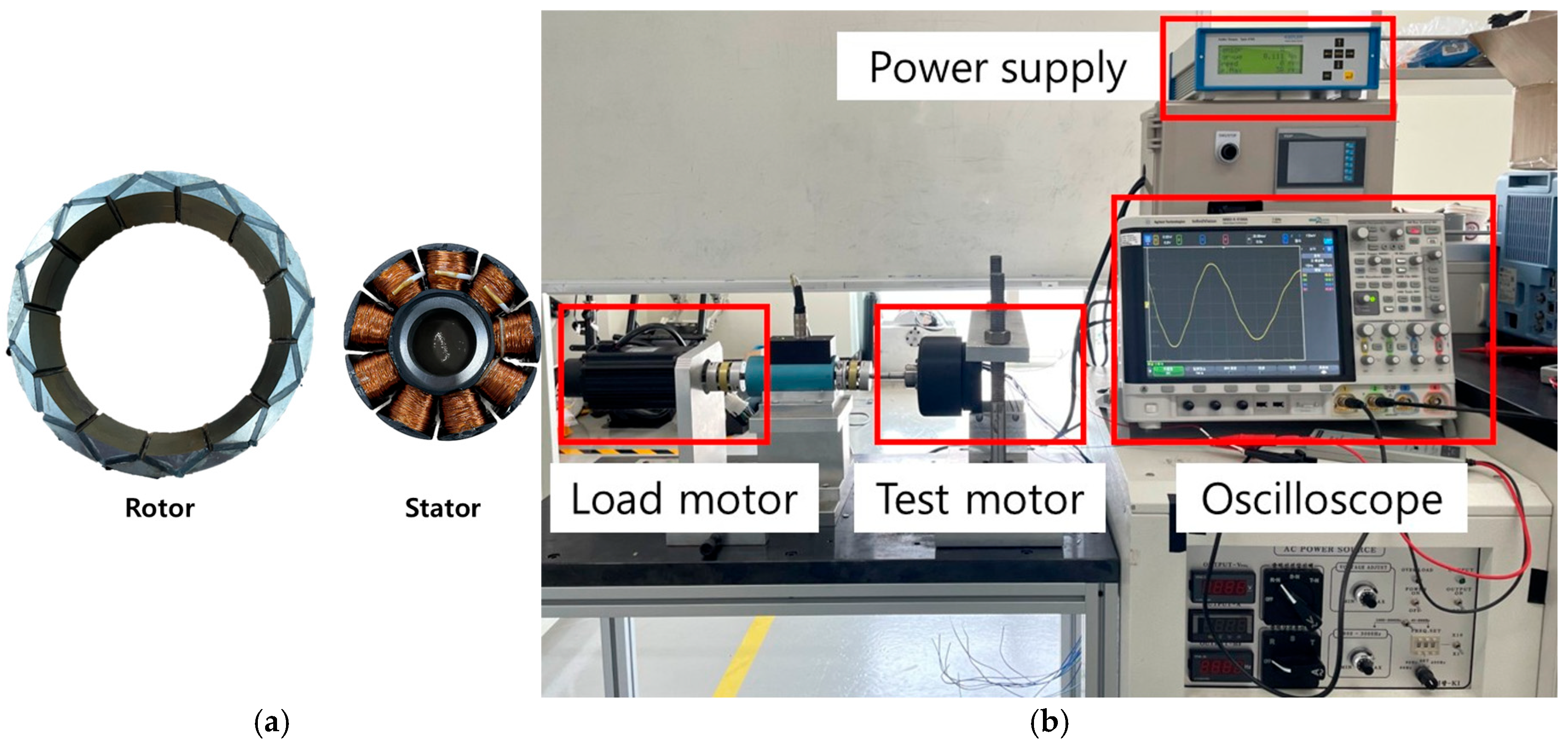
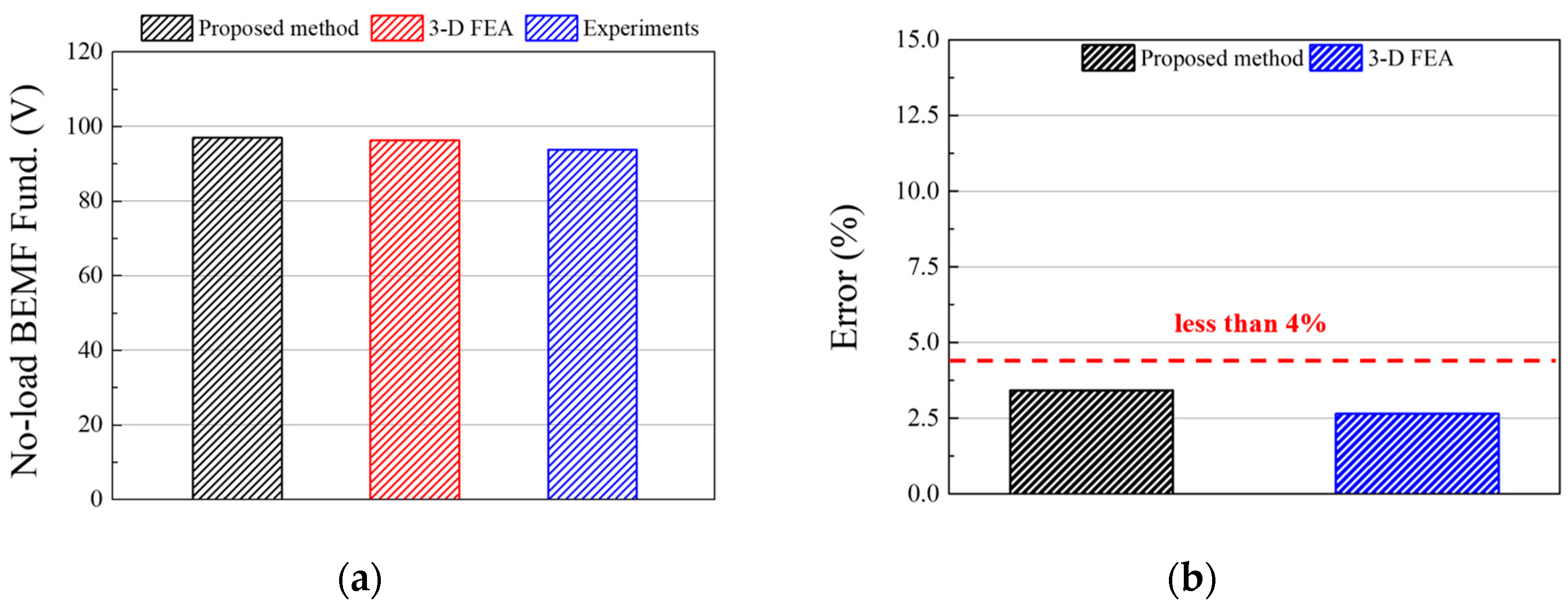
A prototype was developed to experimentally verify the proposed method. The specifications of the prototype are shown in Table 3. The stator-to-rotor volume ratio of the prototype is 11.18, and the rotor has an overhang, making the rotor stack length 11.50 mm longer than the stator stack length. The manufactured prototype and test setup are shown in Figure 6. The test is conducted under no-load conditions at 1000 rpm. Figure 7a compares the no-load BEMF results from the test and the simulation. Both the 3-D FEA and the proposed method exhibit results that closely resemble the experimental data. The error rates shown in Figure 7b confirm the reliability of the proposed method, as both approaches demonstrate errors of less than 4%.

5. Conclusions

This study proposed a performance prediction method for outer rotor permanent magnet synchronous motors using equivalent 2-D FEA, incorporating the influence of 3-D flux phenomena—namely, axial leakage flux and overhang fringing flux. The method introduces correction coefficients derived from a single 3-D FEA reference, which are then applied to 2-D models based on key design variables such as rotor dimensions and stack lengths. To validate the effectiveness of the proposed method, no-load back electromotive force was evaluated at 1000 rpm and compared between the 2-D and 3-D FEA results. The proposed model achieved high prediction accuracy, with the BEMF values closely matching those of full 3-D simulations. Additionally, the BEMF comparison was conducted at multiple speeds, confirming the consistency of the correction approach across various operating points. As the analysis was performed under no-load conditions, only the BEMF coefficient was derived and validated in this study. Torque prediction and torque coefficient evaluation, which require current injection and load operation, are left for future work. Moreover, potential directions for future research include extending the method to dynamic load conditions, analyzing torque ripple, and integrating the approach into optimization routines for early-stage motor design. Overall, the proposed method offers a fast and reasonably accurate alternative to full 3-D FEA during the initial design phase, while still accounting for key 3-D flux effects that are typically neglected in conventional 2-D models.

Author Contributions

Conceptualization, M.-H.S.; methodology, M.-H.S., K.-S.C. and Y.-H.J.; software, M.-H.S.; investigation, K.-S.C.; writing—original draft, M.-H.S.; writing—review and editing, M.-H.S., Y.-H.J., K.-S.C. and M.-S.L.; supervision, M.-S.L.; project administration, M.-S.L. and J.-H.S. All authors have read and agreed to the published version of the manuscript.

Funding

This research received no external funding.

Data Availability Statement

The original contributions presented in this study are included in the article. Further inquiries can be directed to the corresponding author.

Conflicts of Interest

The author, Jae-Han Sim was employed by the company LG Electronics. The remaining authors declare that the research was conducted in the absence of any commercial or financial relationships that could be construed as a potential conflict of interest.

Abbreviations

The following abbreviations are used in this manuscript:
PMSMPermanent Magnet Synchronous Motor
FEAFinite Element Analysis
2-DTwo-Dimensional
3-DThree-Dimensional
BEMFBack Electromotive Force
ALFAxial Leakage Flux
OFFOverhang Fringing Flux
EMCEquivalent Magnetic Circuit

References

  1. Huynh, T.A.; Che, V.H.; Hsieh, M.F. Maximization of High-Efficiency Operating Range of Spoke-Type PM E-Bike Motor by Optimization Through New Motor Constant. IEEE Trans. Ind. Appl. 2023, 59, 1328–1339. [Google Scholar] [CrossRef]
  2. Park, C.S.; Kim, J.H.; Park, S.H.; Yoon, Y.D.; Lim, M.S. Multi-Physics Characteristics of PMSM for Compressor According to Driving Mode Considering PWM Frequency. IEEE Access 2022, 10, 114490–114500. [Google Scholar] [CrossRef]
  3. Li, Y.; Zhao, J.; Fu, J.; Xia, Y.; Wang, W.; Li, X. Performance Comparison of Permanent Magnet Vernier Motors and Permanent Magnet Synchronous Motors. Machines 2025, 13, 390. [Google Scholar] [CrossRef]
  4. Sarac, V.; Minovski, D.; Aneva, S.; Janiga, P.; Smitkova, M.F.; Bogatinov, D.; Atanasova, A. Various Designs of Spoke-Type Permanent Magnet Motor for Performance Optimization. Machines 2025, 13, 375. [Google Scholar] [CrossRef]
  5. Lee, S.H.; Im, S.Y.; Ryu, J.Y.; Lim, M.S. Optimum Design Process of Coaxial Magnetic Gear Using 3D Performance Prediction Method Considering Axial Flux Leakage. IEEE Trans. Ind. Appl. 2024, 60, 3075–3085. [Google Scholar] [CrossRef]
  6. Johnson, M.; Gardner, M.C.; Toliyat, H.A. A parameterized linear magnetic equivalent circuit for analysis and design of radial flux magnetic gears—Part I: Implementation. IEEE Trans. Energy Convers. 2018, 33, 784–791. [Google Scholar] [CrossRef]
  7. Rasmussen, P.O.; Andersen, T.O.; Jorgensen, F.T.; Nielsen, O. Development of a high-performance magnetic gear. IEEE Trans. Ind. Appl. 2005, 41, 764–770. [Google Scholar] [CrossRef]
  8. Seo, J.M.; Jung, I.S.; Jung, H.K.; Ro, J.S. Analysis of Overhang Effect for a Surface-Mounted Permanent Magnet Machine Using a Lumped Magnetic Circuit Model. IEEE Trans. Magn. 2014, 50, 8201207. [Google Scholar] [CrossRef]
  9. Liang, P.; Chai, F.; Yu, Y.; Chen, L. Analytical Model of a Spoke-Type Permanent Magnet Synchronous In-Wheel Motor with Trapezoid Magnet Accounting for Tooth Saturation. IEEE Trans. Ind. Electron. 2019, 66, 1162–1171. [Google Scholar] [CrossRef]
  10. Carraro, E.; Bianchi, N.; Zhang, S.; Koch, M. Design and performance comparison of fractional slot concentrated winding spoke type synchronous motors with different slot-pole combinations. IEEE Trans. Ind. Appl. 2018, 54, 2276–2284. [Google Scholar] [CrossRef]
  11. Jiang, S.; Liu, G.; Zhao, W.; Xu, L.; Chen, Q. Modeling and analysis of spoke-type permanent magnet Vernier machine based on equivalent magnetic network method. Chin. J. Electr. Eng. 2018, 4, 96–103. [Google Scholar] [CrossRef]
  12. Lee, D.; Song, J.Y.; Seo, M.K.; Jung, H.C.; Kim, J.W.; Jung, S.Y. Development of Differing Extent Mesh Adaptive Direct Search Applied for Optimal Design of Spoke-Type PMSM. IEEE Trans. Magn. 2018, 54, 8205905. [Google Scholar] [CrossRef]
  13. Jung, J.W.; Park, H.I.; Hong, J.P.; Lee, B.H. A Novel Approach for 2-D Electromagnetic Field Analysis of Surface Mounted Permanent Magnet Synchronous Motor Taking Into Account Axial End Leakage Flux. IEEE Trans. Magn. 2017, 53, 8208104. [Google Scholar] [CrossRef]
  14. Lee, S.G.; Bae, J.; Kim, W.H. Study on the Axial Leakage Magnetic Flux in a Spoke Type Permanent Magnet Synchronous Motor. IEEE Trans. Ind. Appl. 2019, 55, 5881–5887. [Google Scholar] [CrossRef]
  15. Kim, J.M.; Chai, S.H.; Yoon, M.H.; Hong, J.P. Plastic Injection Molded Rotor of Concentrated Flux-Type Ferrite Magnet Motor for Dual-Clutch Transmission. IEEE Trans. Magn. 2015, 51, 8205204. [Google Scholar] [CrossRef]
  16. Park, M.R.; Jung, J.W.; Kim, D.Y.; Hong, J.P.; Lim, M.S. Design of High Torque Density Multi-Core Concentrated Flux-Type Synchronous Motors Considering Vibration Characteristics. IEEE Trans. Ind. Appl. 2019, 55, 1351–1359. [Google Scholar] [CrossRef]
  17. Park, J.H.; Jung, K.T.; Jung, Y.H.; Lim, M.S.; Yoon, M.H.; Hong, J.P.; Jung, J.W. Design and Verification for the Torque Improvement of a Concentrated Flux-Type Synchronous Motor for Automotive Applications. IEEE Trans. Ind. Appl. 2019, 55, 3534–3543. [Google Scholar] [CrossRef]
  18. Kim, H.J.; Jeong, J.S.; Yoon, M.H.; Moon, J.W.; Hong, J.P. Simple Size Determination of Permanent-Magnet Synchronous Machines. IEEE Trans. Ind. Electron. 2017, 64, 7972–7983. [Google Scholar] [CrossRef]
  19. Park, S.H.; Chin, J.W.; Cha, K.S.; Lim, M.-S. Deep Transfer Learning-Based Sizing Method of Permanent Magnet Synchronous Motors Considering Axial Leakage Flux. IEEE Trans. Magn. 2022, 58, 8206005. [Google Scholar] [CrossRef]
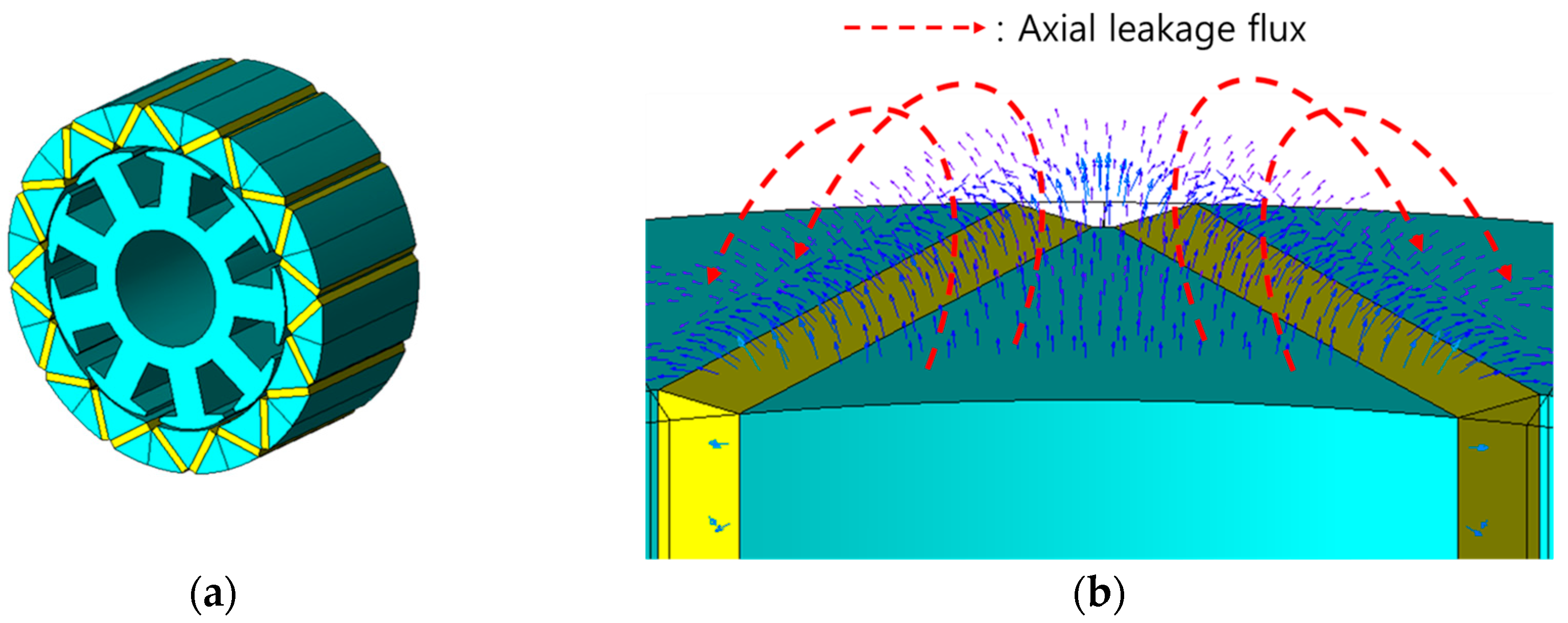
Figure 1. Motor shape and flux path: (a) outer rotor PMSM; (b) axial leakage flux path.
Machines 13 00692 g001
Figure 2. Rotor overhang: (a) overhang structure schematic diagram; (b) overhang fringing flux path.
Machines 13 00692 g002
Figure 3. No-load BEMF differences of 2-D/3-D FEA according to design variables: (a) error according to ALF; (b) error according to OFF.
Machines 13 00692 g003
Figure 4. The flowchart of the proposed method using the 3-D coefficient process.
Machines 13 00692 g004
Figure 5. Result of simulation about no-load BEMF fundamental value: (a) comparison of fundamental amplitude of no-load BEMF; (b) the error compared to the 3-D FEA.
Machines 13 00692 g005
Figure 6. Fabricated motor and no-load test: (a) fabricated prototype model; (b) no-load test.
Machines 13 00692 g006
Figure 7. Comparison of no-load BEMF value with experiments: (a) no-load BEMF fundamental values; (b) error rate compared to experimental values.
Machines 13 00692 g007
Table 1. Design range of PMSM.
ItemUnitValue
Motor type-Outer rotor IPMSM
Number of poles/slots ratio-4:3
Permanent magnets-Ferrite
Stator/rotor core-35PN270
Maximum stack lengthmm50
Stator/Rotor volume ratio-0.3–15.6
Table 2. The amplitudes and analysis times of the no-load BEMF fundamental between the proposed method and 3-D FEA.
Model
Number
kALFkOFFNo-Load BEMF Fund. (Vrms)Error (%)Analysis Time (hour)Number of Elements
(ea)
3-D FEAProposed
Method
3-D FEAProposed
Method
3-D FEAProposed
Method
10.921.2298.9798.900.076.00.2888,08027,150
20.951.2499.6099.540.06888,341
30.911.1785.1684.500.78807,116
40.831.25102.70102.800.10873,902
Table 3. Specification of PMSM.
ItemUnitValue
Stator/rotor volume ratio-11.18
Rotor/stator diameter ratio-1.17
Stack length ratio-1.44
Phase number-3
Phase resistance6.30
Number of turnsturn720
Maximum currentArms2.00
Cooling type-Natural convection
Disclaimer/Publisher’s Note: The statements, opinions and data contained in all publications are solely those of the individual author(s) and contributor(s) and not of MDPI and/or the editor(s). MDPI and/or the editor(s) disclaim responsibility for any injury to people or property resulting from any ideas, methods, instructions or products referred to in the content.