Abstract
To study the typical failure mechanism (rotor unbalance, rotor friction, and rotor crack) and vibration characteristics of the turbocharger rotor system, a rotor system dynamics simulation model was established by an improved four-node aggregate parameter method. The geometric and physical characteristics of the rotor system under three failure states and its dynamics under operation were analyzed. Thus, a typical failure dynamics simulation model of the rotor system was established. On this basis, the output failure simulation signal was extracted using the Hu invariant moment feature extraction method to analyze the system vibration characteristics under each typical failure state of the rotor system. The results show that the model in this paper can effectively reduce the computational volume and computational time, and the errors of numerical simulation were less than 3%. When an unbalance fault occurred in the rotor system, the shaft trajectory was “0” shaped and the response spectrum was dominated by 1X. When the rotor system was frictional, the shaft trajectory was a slightly concave “8” shape, and the response spectrum was dominated by 0.5X. When the rotor system was cracked, the axial trajectory was a “vortex”, and the response spectrum was dominated by 0.5X. Thus, the study of typical failure mechanism and vibration characteristics of a turbocharger rotor system by simulation calculation is effective and has good research prospects, providing an important technical reference for dynamic analysis and fault diagnosis of the rotor system.
1. Introduction
Common failures of turbocharger rotors include rotor imbalance, rotor cracks, rotor touching friction, etc. Therefore, timely and efficient determination of the type of rotor failure is particularly critical in fault monitoring and diagnosis. At present, most of the turbocharger fault diagnosis at home and abroad is based on the fault phenomenon, judgment based on practical engineering experience, with a certain degree of subjectivity, and it is very difficult to obtain experimental data, thus reducing the efficiency and accuracy of fault diagnosis. Therefore, in order to identify the differences between multiple faults more accurately and efficiently, as well as to improve the accuracy and sensitivity of the fault diagnosis of the turbocharger rotor bearing system, it is necessary to simulate the fault simulation of the rotor bearing system and to analyze the fault characteristics in detail.
As the finite element method solves the critical rotor speed with high solution accuracy, it is time-consuming to solve more complex rotor structures. Horner and Pilkey proposed the Riccati transfer matrix method [1], which has the characteristics of rapidness and simplicity in solving the traditional transfer matrix method, as well as ensuring the continuity of matrix data transfer. Ngo et al. [2] analyzed the unbalanced response of the rotor with and without damping according to the finite element method and verified that damping has a certain vibration suppression impact by comparing the peak response. Singh, A. [3] studied the effect of engine excitation on turbocharger performance. It was found that the system exhibits chaotic behavior accompanied by the generation of extensive subsynchronous vibrations at low speed. Hannant [4] studied the dynamic stability of a rotor disk-shaft system under external unbalanced masses and pulsating axial loads. Chao Fu et al. [5] studied the response analysis of an accelerated unbalanced rotating system with random and interval variables. To study the influence of different factors on the dynamics of rotor friction, Guangchi Ying et al. [6] investigated the dynamics of rotor friction failure under the action of base excitation and found that the base excitation exacerbates the severity of rotor friction to a certain extent. Ya Zhang et al. [7] investigated the dynamics of a double-disk rotor-bearing system under axial touching, radial touching, and both together and also analyzed the influence law of rotor speed, the position of the unevenness measure action, and the shell stiffness on the rotor touching characteristics. Liu Guizhen et al. [8] studied the dynamical response of a rotor-stator-bearing system under the action of mass eccentricity variation and nonlinear oil film forces to reveal the system bifurcation characteristics and the pathway into chaos. Ghozlane, M. et al. [9] used a relatively simple normally open crack to study the change in the local flexibility of the crack, further confirming that the presence of the crack will lead to a reduction in stiffness and consequently a decrease in the intrinsic frequency. In addition to the fundamental frequency, 2X and 3X frequency components were also observed in the frequency domain. Jain, A.K. et al. [10] investigated the nonlinear dynamical behavior of a multi-cracked rotor system, considering the effects of crack depth, crack location, and shaft speed, experimentally and analytically. Rotor stiffness is shown to decrease significantly with increasing crack depth. Khorrami, H. et al. [11] studied the vibration response characteristics of a rotor-disc-bearing system containing one and two cracks. The effect of characteristics such as depth, location, and relative angular position of the cracks on the selected vibration characteristics was analyzed and studied. Xiuqin Wang et al. [12] improved the conventional invariant moments to obtain six higher-order improved Hu invariant moments with scale scaling invariance with respect to the conventional Hu invariant moments. Yueh Hara et al. [13] used six improved Hu invariant moments with K-means classifier to better identify the types of storage media. Since the traditional invariant moment matching algorithm requires full pixel traversal each time, which is time-consuming for larger images, Ding Yue et al. [14] obtained good matching results by improving the Hu invariant moment fast matching algorithm using the pyramid model. Yongmei Ren et al. [15] proposed a feature recognition method based on Hu invariant moments, and the results showed that it could effectively provide the recognition rate on the dataset. Lv Chun et al. [16] proposed a Hu invariant moment-based gear fault feature extraction method. However, numerical simulations of typical failures of turbocharger rotor systems and related characteristics have been less studied and analyzed.
In summary, this paper establishes the kinetic models for the common failures of turbochargers, such as rotor unbalance failure, rotor touch wear failure, and rotor crack failure. On the basis of the modeling of the set total parameter method, the rotor bearing system is simplified to a four-disc, three-axis segment model. According to the established model for dynamics analysis, the trajectories of the three faults and the spectral characteristics are derived, and the Hu invariant moment method is used to extract the corresponding typical fault characteristics for the purpose of exploring the fault vibration characteristics. The study in this paper overcomes the limitation of the set total parameter method to calculate a large number of shaft segments. Moreover, compared with the authoritative finite element simulation results, the error is very small, which effectively saves the effective reduction of calculation volume and calculation time.
2. Theoretical Method
2.1. Dynamics Model of a Rotor-Bearing System
The structure of the turbocharger rotor-bearing system is shown in Figure 1a. From left to right are the compressor impeller, the two bearing supports, and the turbine. The dynamics of the turbocharger rotor-bearing system are modeled by the finite element method, and the whole system is simplified to four collector masses of the wheel disc and three shaft segments, as shown in Figure 1.
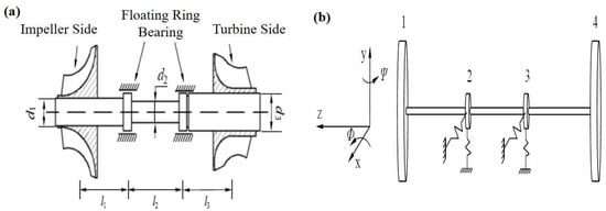
Figure 1.
(a) Schematic diagram of the turbocharger rotor-bearing system. (b) Mechanical model of a turbocharger rotor-bearing system.
Here, 1 is the total mass of the compressor impeller set, 2 and 3 are the total mass of the bearing set, and 4 is the total mass of the turbine set. Considering that the turbocharger rotor is equipped with thrust bearings, which can limit the axial displacement of the rotor, its axial vibration can be neglected. To further investigate the bending vibration of the rotor, its shear effect and torsional vibration can be neglected.
Combining the simplified system in Figure 1, the forces in the shaft segment and the disk in the x-z plane were analyzed separately. The mechanical equations of the i-th wheel and the i-th axle segment can be obtained by using Newton’s second law, which is shown in Equations (1) and (2), respectively.
Consideration of the forces and bending moments of the compressor wheel disc and turbine disc need to satisfy the following conditions:
Assuming that the bearing stiffness is isotropic, the expression for the bearing force at this point is
Substituting the above Equation (4) into Equation (1),
Without affecting the rotor dynamics, the above set of total mass model axle segments is further simplified to 4 wheel discs and 3 axle segments.
2.2. Rotor System Typical Failure Modeling
- (i)
- Rotor imbalance
Under the action of unbalanced mass and unbalanced moment, the rotor system generates a centrifugal force, , which is schematically shown in Figure 2. The direction of the centrifugal force changes by one cycle when the rotating shaft rotates for one week, so the frequency of unbalanced vibration is consistent with the rotational speed. In this section, an unbalanced failure rotor dynamics model at the turbocharger rotor turbine and the compressor impeller is developed.
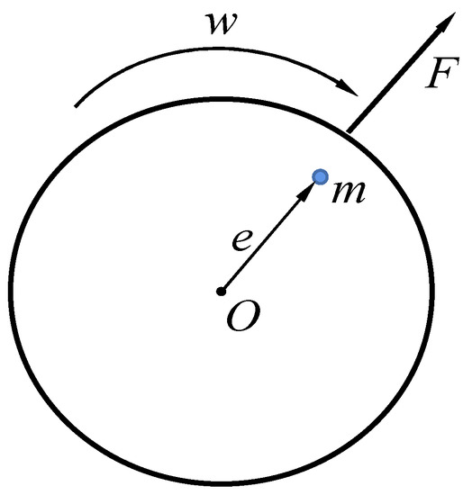
Figure 2.
Diagram of the rotor unbalanced state. Note: is the eccentric mass; is the eccentric distance; F is the centrifugal force; is the angular velocity.
The differential equations of unbalanced motion at the turbocharger rotor turbine and the compressor impeller can be expressed as
In addition, the Capone short-axis oil film force model [17] is used in this paper.
- (ii)
- Rotor bumper modeling
According to the actual turbocharger friction faults and simulation calculations, the first-order vortex mode of the rotor system, the amplitude of the compressor disc is larger than that of the turbine disc, and the friction usually occurs at this location. Therefore, in the dynamics of the study of the turbocharger rotor with frictional failure, only the case of frictional failure on the compressor wheel disc is considered.
The schematic diagram of the rotor touching friction is shown in Figure 3a, and the physical diagram of the impeller blade touching friction damage is shown in Figure 3b.
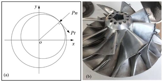
Figure 3.
(a) Diagram of rub-impact. (b) Physical diagram of rub-impact.
Assumptions: (1) The rotor speed is considered constant; (2) the displacement of the rotor in the axial direction is negligible; (3) ignore the gyroscopic effect of the rotor; (4) the collision time between the rotor and stator is very short, the deformation of the stator during the collision can be regarded as linear deformation, and the friction force satisfies Coulomb’s law.
On the basis of the rotor unbalanced fault dynamics model, considering the action mode and mechanical characteristics of the rotor friction fault, the differential equation of rotor motion containing the friction fault can be expressed as follows:
In Equation (7), , , , , , , , , .
- (iii)
- Rotor crack modeling
The supercharger rotor works in the operating range of 3000~42,000 rpm, while the higher speed can ignore the continuous process at full opening and closing. To reflect the stiffness changes caused by the crack opening and closing process during operation, the Mayes cosine wave model was selected as the opening and closing function of the crack stiffness of the supercharger rotor.
Then, the differential equation of motion of the rotor containing the crack fault can be expressed as
where
2.3. Hu Invariant Moment Feature Extraction
Two-dimensional shape invariant moments is a method to identify shapes by extracting invariant moments from images of axial trajectories. The two-dimensional shape invariant moments mainly reflect the image geometric features and mainly contain the mathematical features of invariance such as rotation, translation, and scale stretching. The invariant moment has a clear physical meaning, and the image can be theoretically considered as a thin plate with inhomogeneous mass density, where each order of invariant moment has different meanings: the zero-order moment indicates the total mass of the plate; the first-order moment indicates the center of mass of the plate; and the second-order moment indicates the size and direction of the plate.
Assume that the two-dimensional function is a distribution density function in the plane range , which represents the grayscale at each coordinate point, and is segmentally continuous; then, for any positive integer and , the -th order moment of in the plane is defined in Equation (9):
Considering that the image of the fault axis trajectory is a discrete image, it is necessary to simplify the above equation, Equation (9) in discrete form, see Equation (10):
To simplify the calculation, the axial trajectory has the same gray scale for each coordinate in the plane, ; and the defined gray level outside the axial trajectory is 0, . Then, Equation (10) can be simplified to Equation (11):
In order to make the moment feature translation transform invariant, it is necessary to transform the moment and calculate the central moment of its image. The central moment of the -th order moment of the axial trajectory in the -plane is given in Equation (12):
In order to obtain scale scaling invariance for moment features, is normalized, and the feature set of normalized central moments is used to make the moment features rotationally invariant. The seven normalized invariant moments , obtained in this paper using the Hu invariant moment study are shown in Equation (13):
3. Calculation Conditions and Model Validation
3.1. Rotor System Model Parameters
In order not to affect the dynamics characteristics of the rotor dynamics characteristics, the above set of axle segments of the total mass model is further simplified to four wheel discs and three axle segments, and the dynamics model parameters are specified in Table 1.

Table 1.
Simplified disk-shaft model parameters for a supercharger rotor.
3.2. Model Validation
As can be seen in Table 2, the simplified model of the rotor system proposed in this paper and the Ansys finite element method of the finite element method (FEM) have errors within 3% in the calculation results of the first- and second-order critical speeds, which reduce the errors compared with the traditional Riccati transfer matrix method (TMM).
Table 2.
Comparison of critical speed results.
The above analysis results show that the rotor dynamics model constructed in this paper is in good agreement with the results of the finite element method in solving the rotor inherent frequency, vibration pattern, and shaft trajectory. Therefore, it is considered that the dynamics model constructed in this paper has high accuracy and can be applied to the subsequent research on the fault diagnosis characteristics.
In this paper, the typical fault modeling and vibration characterization scheme of turbocharger rotor system has three steps, as shown in Figure 4, these steps are (1) turbocharger rotor system modeling; (2) turbocharger rotor system failure modeling; and (3) vibration characteristics analysis.
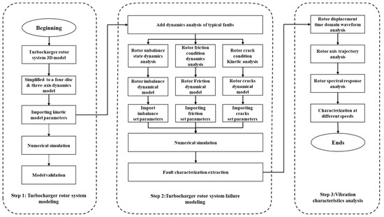
Figure 4.
Flow chart of typical fault modeling and vibration characteristics study of the turbocharger rotor system.
4. Calculation Results and Analysis
4.1. Rotor Unbalanced Fault Characterization
(1) The rotor dynamics response at the impeller end is shown in Figure 5 for an impeller end unbalance of 3.4 × 10⁻⁴ and a rotor speed of 18,000 rpm.
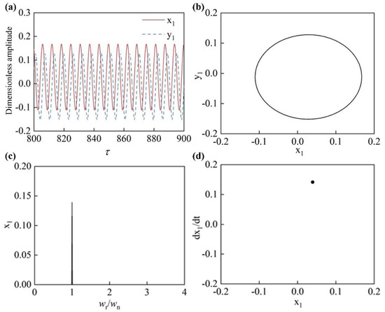
Figure 5.
Rotor dynamic response under unbalanced conditions: (a) time domain curve of impeller displacement change; (b) impeller axis locus; (c) frequency spectrum of the impeller; (d) impeller poincare drawing.
As shown in Figure 5, when the imbalance response occurred at the impeller end, the displacement time domain waveform was a sine wave, the rotor axis trajectory was elliptical, and the rotor showed “a single cycle” motion in the steady running state when there was only one point in the poincare diagram. In addition, as shown in Figure 5c, when the unbalanced response occurred at the impeller end, the response spectrum was dominated by 1X, and the response amplitude was smaller at some higher harmonics such as 2X and 3X.
(2) When the impeller end unbalance was 2 × 10⁻⁴ , the rotor impeller end axial trajectory with increasing rotational speed under rotor unbalance failure at this time was as is shown in Figure 6a. At this time, the spectrum at the corresponding rotational speed is shown in Figure 6b.
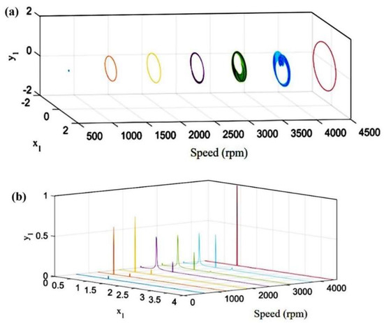
Figure 6.
(a) Rotor axis trajectory at different speeds and (b) rotor spectrum at different speeds.
From Figure 6a, it can be seen that with the increase in speed, the rotor axis trajectory gradually evolved from “0” to “8” and finally returned to “0”. The rotor underwent an oil film vortex during the process described above. However, at the early stage of entering the oil film vortex process, the axial trajectory still showed the typical “0” shape of an unbalance fault, which cannot be correctly judged only from the angle of the axial trajectory. Combined with the rotor spectrum in Figure 6b, it is obvious that a more obvious amplitude of 0.5X appeared in the initial spectrum of the oil film eddy. This is a typical half-speed vortex phenomenon.
4.2. Characterization of Rotor Bumper Fault
For the rotor touching fault, we selected the more obvious fault characteristics of the fixed-point touching fault as a reference object.
(1) The impeller end unevenness was 2 × 10⁻⁴ , the impeller and casing clearance was set to 10 μm, and the speed was 18,000 rpm. The rotor dynamics response at the impeller end is shown in Figure 7.
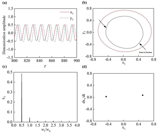
Figure 7.
Rotor dynamic response under rub-impact: (a) time domain curve of impeller displacement change; (b) impeller axis locus; (c) frequency spectrum of the impeller; (d) impeller poincare drawing.
As shown in Figure 7a–c, the displacement time domain waveform was approximately sinusoidal; the rotor axis trajectory was a slightly concave “8” shape; the frequency spectrum was dominated by 0.5X, accompanied by the generation of 1X harmonic of smaller amplitude; and as shown in Figure 6, the displacement time domain waveform was approximately sinusoidal when the fault occurred. Furthermore, as shown in Figure 7d, there were two points on the impeller poincare diagram, which showed that the rotor system entered a “two-cycle” motion when the impeller touched the casing slightly.
(2) The unevenness of the impeller end was 2 × 10⁻⁴ ; we set the clearance between the impeller and the compressor to 5 μm, and the speed was 24,000 rpm, and following this, the rotor dynamics response of the impeller end was as shown in Figure 8.
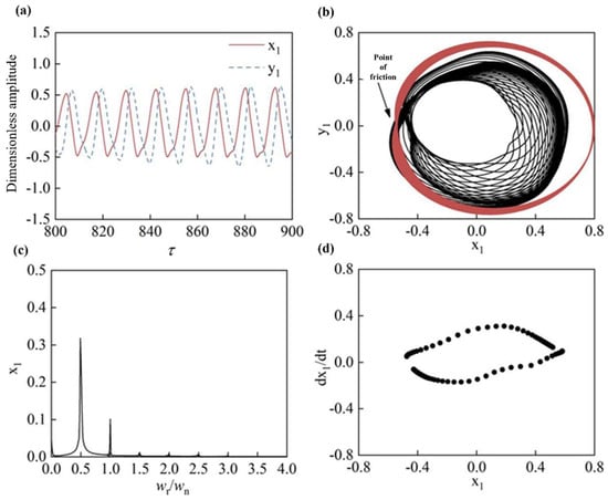
Figure 8.
Rotor dynamic response under rub-impact: (a) time domain curve of impeller displacement change; (b) impeller axis locus; (c) frequency spectrum of impeller; (d) impeller poincare drawing.
As shown in Figure 8a–c, with the deepening of the degree of friction, the rotor x-direction displacement time domain waveform distortion, the y-direction displacement time domain waveform was approximately sine wave; the rotor axis trajectory was a multiloop intertwined gourd “8”; and the spectrum to 0.5X was mainly accompanied by the generation of a smaller amplitude 1X harmonics. Furthermore, as shown in Figure 8d, there were multiple points on the impeller poincare diagram consisting of an approximate ring shape, showing that the rotor system entered into the proposed cyclic motion when the impeller was in severe contact with the casing.
(3) When the impeller end unevenness was 2 × 10⁻⁴ , we set the impeller and casing clearance of the compressor to 10 . The axial trajectory of the impeller end of the rotor with increasing speed under the fixed-point touching fault is shown in Figure 9a. At this point, the spectrum at the corresponding speed was as is shown in Figure 9b.
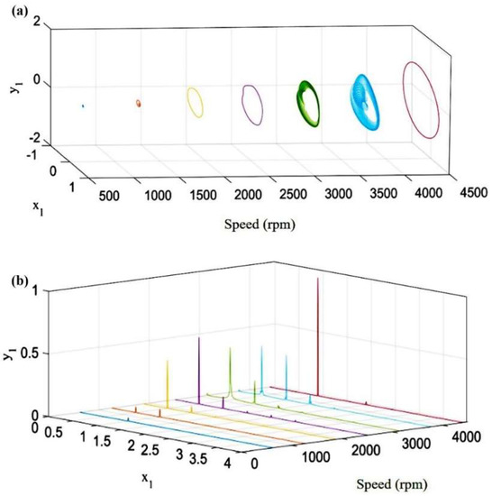
Figure 9.
(a) Rotor axis trajectory at different speeds. (b) Rotor spectrum at different speeds.
As can be seen from Figure 9a, with the increase in speed, the rotor axis trajectory from the unbalanced predominant “0” to the oil film vortex concave “8” shape, with the fixed point of touching friction, the axis trajectory became a slight concave “8” shape, with the deepening of the touching friction gradually evolving into a multi-ring intertwined concave “8” shape, which finally returned to the “0” shape. When combined with the spectrum shown in Figure 9b, it can be found that the friction fault was more likely to excite the oil film vortex at low speed, and the rotor axis trajectory at high speed showed the “0” shape of the unbalance fault, which cannot be correctly judged only from the axis trajectory angle. Comparing the spectrum components shown in Figure 6b, we found that there were 2X more components for the touch-motion fault at high speed than for no touch-motion, and thus it can be seen that the spectrum components can be used to enrich the fault characteristics.
4.3. Rotor Cracking Fault Characterization
(1) The impeller end unevenness was 3.4 × 10⁻⁴ , the crack location was located near the journal of the impeller end of the compressor, the crack depth a/R = 1, the crack opening and closing angle was /2, the vortex angle was 0 degrees, and at this time the speed was 18,000 rpm; the rotor dynamics response results are shown in Figure 10.
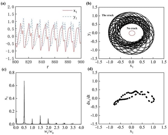
Figure 10.
Rotor dynamics response under rub-crack: (a) time domain curve of impeller displacement change; (b) impeller axis locus; (c) frequency spectrum of impeller; (d) impeller poincare drawing.
As shown in Figure 10a–d, when a crack failure occurred near the compressor impeller end journal, the displacement time domain waveform was distorted; the rotor axis trajectory was shaped as a “swirl”. The frequency spectrum was dominated by 0.5X, and the frequency component was mainly caused by the oil film vortex, while a higher peak value appeared at the 1.5X harmonic times, accompanied by the generation of 1X, 2X, 3X, and other octave components, combined with poincare diagrams can be found in the rotor axis for a number of scattered intertwined; the rotor system can be judged to be in the proposed periodic motion.
(2) The impeller end unevenness was 3.4 × 10⁻⁴ , the crack location was located near the impeller end journal, the crack depth a/R = 1, the crack opening and closing angle was /2, the vortex angle was 0 degrees, and the rotor dynamics response results were as shown in Figure 11 at the speed of 34,800 rpm.
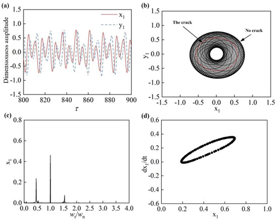
Figure 11.
Rotor dynamics response under rub-crack: (a) time domain curve of impeller displacement change; (b) impeller axis locus; (c) frequency spectrum of impeller; (d) impeller poincare drawing.
As shown in Figure 11a–d, when the crack fault occurred near the compressor end impeller, the displacement time domain waveform showed a wave-like pattern. The rotor axis trajectory was “petal” shaped; the spectrum was dominated by 1X, while higher peaks appearing at 0.5X and 1.5X harmonics, combined with the Poincare diagram, were found in the rotor axis for a number of scattered points formed by the “0”, and the rotor system could be judged to be in the proposed periodic motion.
(3) The rotor crack fault was set as follows: the impeller end unevenness was 3.4 × 10⁻⁴ , the crack location was near the journal of the impeller end of the compressor, the crack depth a/R = 1, the crack opening and closing angle was /2, and the vortex angle was 0 degrees. At this time, the axial trajectory of the rotor impeller end under the crack fault with increasing rotational speed is shown in Figure 12a. At this time, the spectrum at the corresponding rotational speed is shown in Figure 12b.
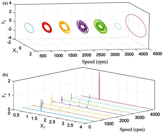
Figure 12.
(a) Rotor spectrum at different speeds. (b) Rotor spectrum at different speeds.
From Figure 12a, it can be seen that as the speed increased, the rotor axis trajectory gradually evolved from the “0” when it was unbalanced to the “vortex” shape with multiple intertwined rings and finally returned to the “0” shape. Compared with the interlacing complexity of the rotor shaft trajectory, the crack fault characteristics were more intuitive in the spectrum, as shown in Figure 12b; with the increase in speed, the rotor crack fault excited more obvious 1.5X and 2X components in amplitude.
5. Conclusions
In this study, for the common failures of turbochargers (rotor unbalance failure, rotor touch wear failure, and rotor crack failure), the rotor bearing system was developed as a four-disc, three-axis segment model on the basis of the aggregate parameter method modeling. The characteristics of the output fault simulation signals were extracted using Hu invariant moments. The system vibration characteristics for each typical fault state of the rotor system were analyzed, and some key findings are as follows:
- (1)
- Compared with the traditional set total parameter method, the improved four-node centralized parameter method overcame the limitation of calculating a large number of axis segments and effectively reduced the calculation volume and calculation time. By comparing the critical speed calculation results of FEM and TMM, the errors were found to be less than 3%, which proves the reliability of the model established in this paper.
- (2)
- When the unbalance fault occurred in the rotor system, the displacement time domain waveform approximated a sine wave, and the rotor axis trajectory was “0” shaped. In the steady state of operation, the rotor exhibited single-cycle motion, and its response spectrum was dominated by 1X.
- (3)
- When the rotor system had a friction fault, the displacement time domain waveform was similar to a sine wave, and the rotor axis trajectory was a slightly concave “8” shape, with 0.5X dominating the frequency spectrum. When the friction fault was light, the rotor system entered a two-cycle motion. When the friction fault was more serious, the rotor system entered the proposed cycle motion.
- (4)
- When a crack fault occurred near the impeller journal, the displacement time domain waveform was distorted and the rotor axis trajectory was “vortex” shaped, and the response spectrum was dominated by 0.5X, which was mainly caused by the oil film vortex. At the same time, the crack failure also caused a significant vibration peak at the 1.5X harmonic. The combined effect put the rotor system in a proposed periodic motion.
Author Contributions
Conceptualization, J.W.; Methodology, J.W.; Software, J.D.; Validation, J.W. and H.S.; Formal analysis, H.Q.; Writing—review & editing, H.W., J.G. and J.Z. All authors have read and agreed to the published version of the manuscript.
Funding
This work was supported by Postgraduate Research and Practice Innovation Program of Jiangsu Province (SJCX21_1788).
Data Availability Statement
The data that support the findings of this study are available on request from the corresponding author, [H.W.], upon reasonable request.
Conflicts of Interest
The authors declare no conflict of interest.
Nomenclature
| X | The displacements of the wheel along the x directions |
| Y | The displacements of the wheel along the y directions |
| Φ | The angles of rotation of the wheel in the x-axis directions |
| Ψ | The angles of rotation of the wheel in the y-axis directions |
| m | The mass of the wheel |
| Jdi | The diameter inertia |
| Jpi | The pole inertia |
| E | The modulus of elasticity |
| I | The moment of inertia of the section |
| l | The length of the shaft section |
| wr | The rotor speed |
| e | The distance between the centers of the wheel |
| t | Time |
| F | Force |
| M | The bending moment |
| The cross-sectional moment of the shaft section | |
| The shear factor, | |
| The cross-sectional coefficient (0.886 for solid circular shafts and about 2/3 for thin-walled hollow shafts) | |
| The vector of degrees of freedom of the rotor | |
| The mass matrix of the rotor | |
| The rotor stiffness matrix | |
| The gyro matrix | |
| The excitation force vector | |
| The total mass at the impeller of the compressor | |
| The total mass at the bearing near the impeller | |
| The total mass at the bearing near the turbine | |
| The total mass at the turbine | |
| Damping at the compressor impeller | |
| Damping near the impeller bearing | |
| Damping near the turbine bearing | |
| Damping at the turbine | |
| The bending stiffness of the shaft segment | |
| The eccentric mass at the impeller | |
| The eccentricity at the turbine of the compressor | |
| The component of the oil film force in the x-direction | |
| The component of the oil film force in the y-direction | |
| The distance between the rotor and stator of the supercharger | |
| FEM | Finite element method |
| TMM | Riccati transfer matrix method |
References
- Horner, G.C.; Pilkey, W.D. The Riccati Transfer Matrix Method. J. Mech. Des. 1978, 100, 297–302. [Google Scholar] [CrossRef]
- Ngo, V.T.; Xie, D.; Xiong, Y.; Zhang, H.; Yang, Y. Dynamic analysis of a rig shafting vibration based on finite element. Front. Mech. Eng. 2013, 8, 244–251. [Google Scholar] [CrossRef]
- Singh, A.; Gupta, T.C. Effect of rotating unbalance and engine excitations on the nonlinear dynamic response of turbocharger flexible rotor system supported on floating ring bearings. Arch. Appl. Mech. 2020, 90, 1117–1134. [Google Scholar] [CrossRef]
- Phadatare, H.P.; Pratiher, B. Dynamic stability and bifurcation phenomena of an axially loaded flexible shaft-disk system supported by flexible bearing. Proc. Inst. Mech. Eng. Part C J. Mech. Eng. Sci. 2020, 234, 2951–2967. [Google Scholar] [CrossRef]
- Fu, C.; Xu, Y.; Yang, Y.; Lu, K.; Gu, F.; Ball, A. Response analysis of an accelerating unbalanced rotating system with both random and interval variables. J. Sound Vib. 2020, 466, 115047. [Google Scholar] [CrossRef]
- Guangchi, Y. Fundamental Excitation Identification and Rotor Dynamics of Turbocharger. Ph.D. Thesis, Shanghai Jiaotong University, Shanghai, China, 2008. [Google Scholar]
- Zhang, Y.; Wang, W.; Yao, J. Analysis of axial-radial friction nonlinear dynamics of a double-disk rotor system. Vib. Shock 2012, 31, 141–145. [Google Scholar]
- Liu, G.; Yu, Y.; Ma, X.; Haijuan, D.; Ding, H.; Wen, B. Nonlinear analysis of bumper rotor under the influence of mass eccentricity. Chin. J. Constr. Mach. 2016, 14, 21–25+31. [Google Scholar]
- Ghozlane, M. Dynamic Response of Cracked Shaft in Rotor Bearing-Disk System. Lect. Notes Control. Inf. Sci. 2015, 789, 615–624. [Google Scholar]
- Jain, A.K.; Rastogi, V.; Agrawal, A.K. Experimental Investigation of Vibration Analysis of Multi-Crack Rotor Shaft. Procedia Eng. 2016, 144, 1451–1458. [Google Scholar] [CrossRef]
- Khorrami, H.; Rakheja, S.; Sedaghati, R. Vibration behavior of a two-crack shaft in a rotor disc-bearing system. Mech. Mach. Theory 2017, 113, 67–84. [Google Scholar] [CrossRef]
- Xiuqin, W.; Hongyang, X. Improvement of invariant moment algorithm and human ear recognition technology. J. Heilongjiang Inst. Sci. Technol. 2008, 1, 51–53+57. [Google Scholar]
- Yue, Y.; Hong, W.; Peixin, Y.; Chang, W. An improved Hu-invariant moment algorithm for storage media image recognition. J. Instrum. 2016, 37, 1042–1048. [Google Scholar]
- Ding, Y.; Wu, J.J.; Jiang, Y.; Jiexian, Z. Fast image matching algorithm based on improved HU invariant moments. Sens. Microsyst. 2020, 39, 124–127. [Google Scholar]
- Ren, Y.; Yang, J.; Zhang, Q.; Guo, Z. Ship recognition based on Hu invariant moments and convolutional neural network for video surveillance. Multimed. Tools Appl. 2020, 80, 1343–1373. [Google Scholar] [CrossRef]
- Lv, C.; Zhang, P.; Wu, D. Gear Fault Feature Extraction Based on Fuzzy Function and Improved Hu Invariant Moments. IEEE Access 2020, 8, 47490–47499. [Google Scholar] [CrossRef]
- Adiletta, G.; Guido, A.R.; Rossi, C. Chaotic motions of a rigid rotor in short journal bearings. Nolinear Dyn. 1996, 10, 251–269. [Google Scholar] [CrossRef]


Disclaimer/Publisher’s Note: The statements, opinions and data contained in all publications are solely those of the individual author(s) and contributor(s) and not of MDPI and/or the editor(s). MDPI and/or the editor(s) disclaim responsibility for any injury to people or property resulting from any ideas, methods, instructions or products referred to in the content. |
© 2023 by the authors. Licensee MDPI, Basel, Switzerland. This article is an open access article distributed under the terms and conditions of the Creative Commons Attribution (CC BY) license (https://creativecommons.org/licenses/by/4.0/).