Article

Gear Crack Detection Based on Vibration Analysis Techniques and Statistical Process Control Charts (SPCC)

1
Laboratory of Mechanics, Modeling and Production (LA2MP), National School of Engineers of Sfax, Sfax BP1173-3038, Tunisia
2
Ministry of Construction, Housing, Municipalities and Public Works, Diyala Governorate, Diyala IQ32001, Iraq
*
Author to whom correspondence should be addressed.
Machines 2023, 11(2), 312; https://doi.org/10.3390/machines11020312
Submission received: 1 January 2023 / Revised: 2 February 2023 / Accepted: 11 February 2023 / Published: 20 February 2023
(This article belongs to the Section Machines Testing and Maintenance)

Abstract

:
Vibration condition monitoring is a non-devastating technique that can be performed to detect tooth cracks propagating in gear systems. This paper proposes to apply a new methodology using time-domain analysis, frequency-domain analysis, and statistical process control charts (SPCC) for gear crack detection of a 10 DOF dynamic model of spiral bevel gear system (SBGS). The gear mesh stiffness effect used in the model has been studied analytically for different levels of crack faults. Adding Gaussian white noise is discussed as the first step to simulating the initial modeling signals of real-world conditions. Second, time-domain signal analysis was performed to identify periodic vibration pulses as failure components and calculate the statistical standard deviation (STD) feature as a fault-sensitive feature. Third, a fast Fourier transform (FFT) to time signals of the variable gear mesh stiffness was applied to determine the gear mesh frequency and sidebands to detect tooth cracks. Fourth, the SPCC was designed using the Shewhart X-bar chart and an exponentially weighted moving average (EWMA) chart based on the STD feature of the healthy gears. Finally, in the testing stage, the control charts are carried out with simulation signals under faulty conditions to detect the different levels of cracks. The results showed that the EWMA chart outperformed the time domain analysis, frequency domain analysis, and Shewhart X-bar chart in detecting all levels of cracks at an early stage.

1. Introduction

The condition monitoring (CM) of rotating machines, including spiral bevel gear systems (SBGS), used in power transmission, industrial production, and modern manufacturing machinery, has attracted the increasing interest of industrialists and researchers in this field [1]. Gear cracks are one of the most common failures in bevel gear systems; they can occur due to excessive torque, poor lubrication, manufacturing or installation defects, or simply end-of-life fatigue [2]. Early detection of cracks can prevent unexpected machine breakdowns, improve product quality, increase the production and reliability of modern rotating machines, and provide safety for people [3]. Therefore, it is necessary to investigate crack fault detection in the bevel gear transmission system for mechanical status assessment and health maintenance.
In this field, dynamic modeling of gear systems has proven to be an effective method for analyzing and understanding the dynamics behavior of gear systems during a fault. The time-varying meshing stiffness (TVMS) plays an essential role in the vibration response excitation of the dynamic models and can be used to represent local gear defects [4]. Consequently, the search for methods for crack fault detection caused by changes in the gear mesh stiffness has become the emphasis and attention of foreign and local scholars [5,6]. Most studies carried out in the last two decades have focused on crack defect detection using vibration analysis techniques in spur gear systems [7,8,9,10,11]. In contrast, some works in the literature have been found related to fault detection in bevel gear models caused by TVMS fluctuations, such as cracks, wear, and breakage. For instance, Yassin et al. [12] developed a numerical method of the 3D-dynamic model of a two-stage straight bevel gear to study the change effect in mesh stiffness to detect manufacturing and tooth crack defects using time and frequency domain analysis methods and compare the dynamic behavior of the system under healthy and faulty conditions. Figlus and Wilk [13] used an envelope spectrum analysis to diagnose tooth chipping and wear faults. Hu et al. [14] developed a vibration indicator extracted from gear signals using time synchronous averaging (TSA). This gear status indicator consists of the sideband ratios of a number of mesh frequency harmonics to monitor different wear faults. Yang et al. [15] presented a dynamic model of a spiral bevel gear transmission with torsional vibration response, friction excitation, and time-varying mesh stiffness. Then, model vibration response was analyzed to detect various broken tooth failures at minor fault severity (10–30%) and severe fault severity (30–60%) using statistical features of time domain and frequency domain components. Figlus [16] introduced a new method for processing the gearbox vibration signal in means of transport. The method combined multi-stage filtering and entropy. The results showed the effectiveness of the presented technique in extracting symptoms of gear damage from the complex gearbox vibration signal. Dewangan et al. [17] proposed a mesh stiffness model for a single-stage bevel gearbox to calculate the dynamic response with a missing tooth fault. The defect feature characteristics were determined using signal processing methods in the time and frequency domain, and the simulation results were compared with the experimental results. Han et al. [18] used different statistical indices for both time and frequency domains to determine the tooth root cracking faults with different crack degrees obtained from the repeated reduction in time-varying mesh stiffness (TVMS) under the influence of assembly errors in a spiral bevel gear (SBG) transmission system established by a finite element (FE). Mauricio et al. [19] used a diagnostic indicator called squared envelope spectrum(SES) for early and accurate detection of gear failures
Furthermore, the detection of bevel gear tooth failures caused by the impact of mesh stiffness variation under non-stationary dynamic conditions was performed. Karray et al. [20] studied the TVMS influence on the dynamic response of a spiral bevel gear with a local defect under load and speed variable states. The results showed that time-frequency analysis is more suitable for detecting tooth cracks than spectral analysis. Ziani et al. [21] developed a signal processing technique using an Empirical Mode Decomposition(EMD), Teager–Kaiser Energy Operator (TKEO), and shock detector (SD) to investigate the behavior of time-varying mesh stiffness (TVMS) for detecting crack defects at different levels using simulated vibration data obtained from a dynamic model of a spiral bevel gearbox operating under non-stationary conditions. Chaari et al. [22] presented a dynamical model of a spiral bevel gear under stationary and non-stationary operating conditions and time-varying mesh stiffness (TVMS). Using the jerk, the acceleration derivative, different levels of local tooth defects in the gearbox were diagnosed.
Meanwhile, some researchers have identified failures of bevel gear models resulting from TVMS effects and transmission (TE) errors. Zhu et al. [23] studied the effects of time-varying mesh stiffness (TVMS), transmission error (TE), gearbox flexibility, unbalanced excitation, flexible shaft, and bearing support of the full coupling system vibration of spiral bevel gears. In the same way, Peng et al. [24] performed a transmission error change (TE) investigation using a lumped parameter model (LPM) to diagnose localized defects, namely cracks and spalling, using a finite element model.
Besides that, Cao et al. [25] propose a Tribo-dynamic model for spiral bevel gears through an iterative numerical scheme to correlate a non-linear dynamic model of 8-DOF with a lubrication model. To simulate fatigue life analysis using the rolling contact stress life (RCSF) model. Further, Molaie et al. [26] analyzed the non-linear dynamic behavior and time-variation of a spiral bevel gear pair with different cases of axial and radial misalignments using time responses, phase portraits, Poincare maps, and bifurcation diagrams.
Recently, the statistical process control charts (SPCC) technique has attracted great interest in the fault detection of gear systems [27,28]. SPCC has several advantages, including shorter computational capacity with fewer data, fault detection in less time, and ease of application [28]. Nevertheless, studies in [27,28] focused on applying the SPCC technique to detect fracture and wear faults in spur gear systems, even though they have yet to be widely used in real life. Besides, SPCC has not been applied to detect crack defects that are difficult to produce in experimental tests, especially in producing small cracks with precise dimensions.
To sum up, according to the literature mentioned above, scholars have conducted many research studies on the dynamic behavior of gear transmissions with failures. Only a few studies included detecting crack faults at small levels by time-varying mesh stiffness excitation in the SBGS. In order to fill this research gap, this paper aims to investigate the behavior of linear dynamics of an SBGS, which relies on the described method in [20,21,29] for time-varying mesh stiffness (TVMS) calculation as the starting point. The novelty of this study is in investigating the variation effect of the gear mesh stiffness with different percentages to represent small levels of tooth crack defects using vibration analysis techniques and statistical process control charts (SPCC). Time domain and frequency domain analysis methods are used to detect the periodic fluctuations and sidebands caused by the TVMS changes. Then, the SPCC approach was applied using the Shewhart X-bar and the exponentially weighted moving average (EWMA) charts. The results demonstrated that the EWMA control chart is superior to the vibration analysis methods and Shewhart X-bar chart in detecting all levels of cracks. The sections of the paper are organized as follows. Section 2 describes the dynamic model of SBGS. Section 3 presented the proposed methods and procedures for crack fault detection. Section 4 offered the results and discussion. Finally, Section 5 explains the conclusions and future work.

2. Theoretical Modeling of the Transmission System

2.1. Dynamic Modeling of a Spiral Bevel Gear System (SBGS)

A single-stage spiral bevel gear system model is considered [21] with 10 degree of freedom (DOF), as shown in Figure 1. This transmission is presented by two rigid blocks consisting of a pinion and a wheel. The pinion is joined to the motor for the input shaft, and the wheel is coupled to the receiver shaft (load). The 5 DOF are assigned to each block. x i , y i , z i ( i = 1 , 2 ) are three translational displacements, θ 1 and θ 2 are rotations of the pinion and wheel, respectively, and θ m and θ r are rotations of the motor and receiver (load) shafts, respectively. The two gear bodies are treated as rigid cone disks and the shafts are presented by torsional stiffness. The following assumptions were made of the model:
  • The transmission system operates under stationary conditions;
  • Linear springs are used to represent the stiffness generated by the gears meshing;
  • The frictional force effect that occurs while meshing is disregarded;
  • Any effects of errors in assembly and manufacturing are neglected;
  • There is no consideration for any transmission errors;
  • Due to the low rotational speed, the Coriolis force was neglected;
  • Damping is considered Rayleigh damping.

2.2. Equation of Motion of the System

After defining the model specifications, the equation of motion of the system is computed through Newmark’s method [21,30] and obtained by applying Lagrange formulation and is given by:
M q ¨ + C q ˙ + K ( t ) q = F
where M is a diagonal mass matrix, C is the proportional Rayleigh damping matrix, K ( t ) is the stiffness matrix.
The degree of freedom (DOF) vector of the system is defined as:
q = { x 1 , y 1 , z 1 , θ m , θ 1 , x 2 , y 2 , z 2 , θ 2 , θ r } T
The diagonal mass matrix (M) of the system is defined as:
M = [     m 1 m 1 0 m 1 0 I m I 1 m 2 m 2 m 2 I 2 I r ]
where m1 and m 2 are the mass of the first block and the mass of the second block, respectively. I m , I r , I 1 , I 2 are the moments of inertia that are associated with the motor, the receiver, the pinion, and the wheel gear, respectively.
F is the applied external torque vector and defined as:
F = { 0 , 0 , 0 , C m , 0 , 0 , 0 , 0 , 0 , C r } T
where C m and C r are the driving and the loading torque, respectively.
Based on the premise that the transmission operates under a constant and permanent system, so the driving torque is related to the loading torque, as follow:
C r = Z 2 Z 1 C m
where Z 1 and Z 2 the numbers of teeth on the pinion and the wheel, respectively.

2.3. Modeling of Gear Mesh Stiffness

This part describes the procedure for modeling the temporal fluctuation of the two-meshing stiffness of spiral bevel gears.
In a gear system, gear mesh stiffness is a time-varying metric because the number of connected teeth changes by the contact ratio. Moreover, the mesh stiffness changes continuously with changing location and direction of the forces applied to the tooth through the meshing duration [9]. The mesh stiffness shows a reduction during the gear tooth fault. The ratio of this reduction is different according to the magnitude of the fault during the defective tooth meshing period.
In this model, the mesh stiffness is modeled through a linear stiffness k e ( t ) . It is modeled as a trapezoidal function a minimum value of this function corresponds to 1 pair in mesh, and the maximum one corresponds to 2 pairs in contact, as shown in Figure 2.
The stiffness matrix K ( t ) , can be defined as follows:
K t = s 2 k e + k x 1 - s 6 k e - s 4 k e 0 - s 9 k e - s 2 k e s 6 k e s 4 k e s 10 k e 0 - s 6 k e s 3 k e + k y 1 s 5 k e 0 s 11 k e s 6 k e - s 3 k e - s 5 k e - s 12 k e 0 - s 4 k e s 5 k e s 1 k e + k z 1 0 s 7 k e s 4 k e - s 5 k e - s 1 k e - s 8 k e 0 0 0 0 k θ 1 - k θ 1 0 0 0 0 0 - s 9 k e s 11 k e s 7 k e - k θ 1 s 13 k e + k θ 1 s 9 k e - s 11 k e - s 7 k e - s 15 k e 0 - s 2 k e s 6 k e s 4 k e 0 s 9 k e s 2 k e + k x 2 - s 6 k e - s 4 k e - s 10 k e 0 s 6 k e - s 3 k e - s 5 k e 0 - s 11 k e - s 6 k e s 3 k e + k y 2 - s 5 k e s 12 k e 0 s 4 k e - s 5 k e - s 1 k e 0 - s 7 k e - s 4 k e - s 5 k e s 1 k e + k z 2 s 8 k e 0 0 0 0 0 0 0 0 0 - k θ 2 k θ 2 s 10 k e - s 12 k e - s 8 k e 0 - s 15 k e - s 10 k e s 12 k e s 8 k e s 14 k e + k θ 2 - k θ 2
where ke is the function that defines the time-varying gearmesh stiffness; k x i ,   k y i and k z i   ( i = 1 , 2) are the bearing stiffness of each block. k θ i ( i = 1 , 2 ) are the torsional stiffness of the shafts. The coefficients S j ( j = 1 15 ) are given in Table 1.
The mesh stiffness matrix K ( t ) can be decomposed into called a mean stiffness matrix K m and a variable matrix k ( t ) expressed by:
K ( t ) = K m + k ( t )
C is the proportional Rayleigh damping can be defined as:
C = 0 · 05   M + 10 4   K m

3. The Proposed Methodology for the Gear Fault Detection

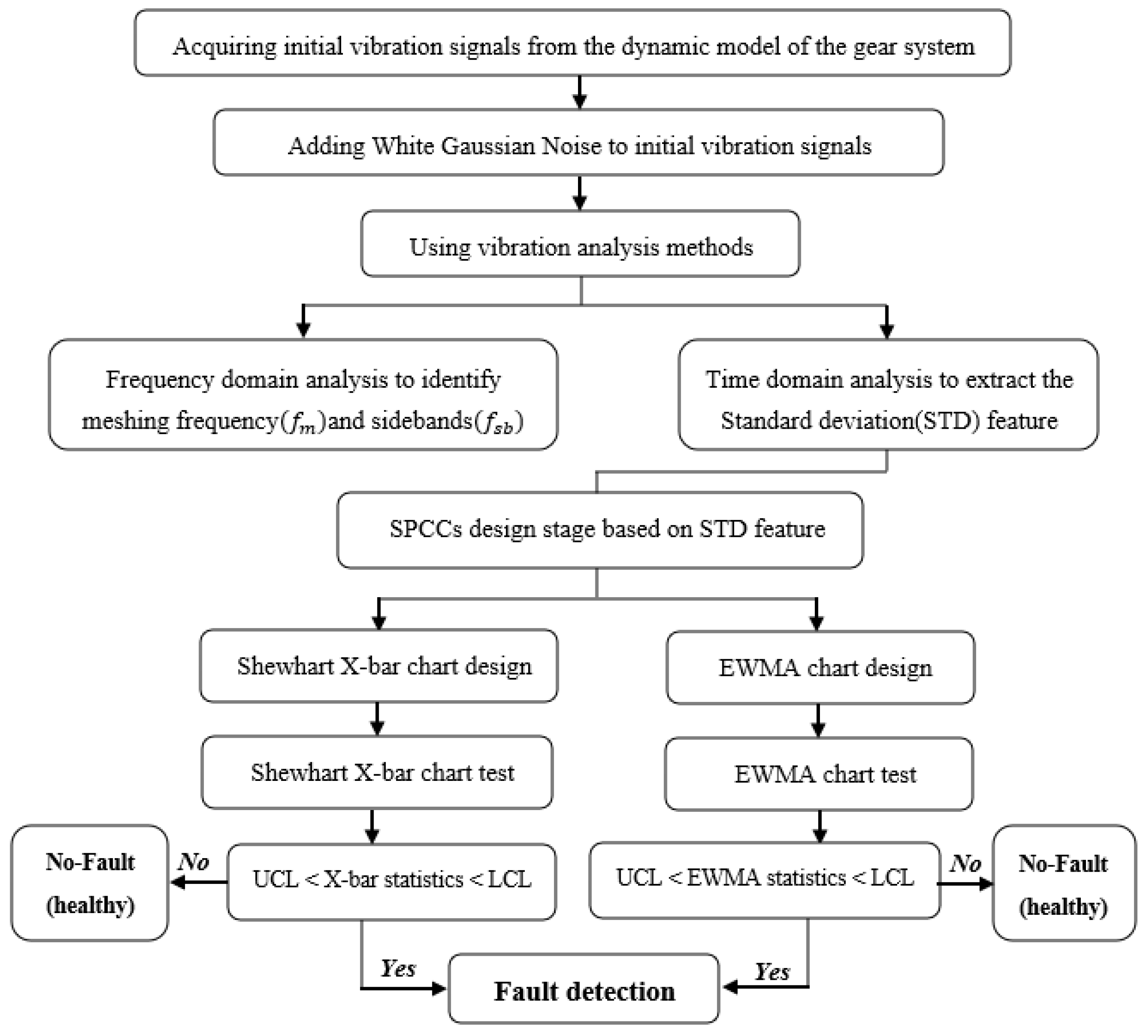
Figure 3 shows a flow chart depicting the proposed gear fault detection methodology based on the vibration analysis methods and statistical process control charts (SPCC) approach. This methodology is divided into the subsequent steps:
  • Data acquisition: the initial simulated vibration signals are obtained from the dynamic model described in Section 2. Next, as a first step, a noise-add simulation of the initial signals is performed using noise contrast and signal-to-noise ratio (SNR) to simulate work conditions for raw signals as in real practice;
  • Data processing: Vibration analysis methods, including both time domain analysis and frequency domain analysis, are used for vibration signals after they are divided into segments as short-time signals. Firstly, the time-domain signal is analyzed to detect periodic pulse and calculate the standard deviation (STD) feature as a fault-sensitive statistical feature and then used to design and test the SPCC. Secondly, the vibration signal is analyzed in the frequency domain using fast Fourier transform (FFT) analysis to identify meshing frequency ( f m ) and sidebands ( f s b ) that are associated with different crack levels.
  • The design stage of statistical process control charts (SPCC): Univariate statistical control charts are designed, each of the Shewhart X-bar chart and the exponentially weighted moving average (EWMA) chart, depending on the standard deviation (STD) feature under healthy gear system conditions and the establishment of upper control limits (UCL) and lower control limits (LCL) for the SPCC;
  • The test stage for statistical process control charts (SPCC): In this step, Shewhart X-bar and EWMA control charts are tested using the same UCL and LCL as in the healthy status charts to detect different levels of the crack defect in the root tooth of the pinion.
Next, we will briefly describe the methods that have been applied, i.e., the procedure for noise simulation, the vibration analysis methods, and the statistical process control charts (SPCC).

3.1. Noise Simulation of Raw Signals

Gearbox vibration signals are often contaminated by a combination of noise from other gearbox components (shafts and bearings) and environmental conditions of gear working. Therefore, the conditions for the initial simulated signals obtained from the dynamic modeling should be similar to those in real life. When there is no gearbox fault, i.e., when the gearbox operates normally, the vibration signal consists only of white background noise, which is usually interpreted as a Gaussian distribution. Whenever the gearbox is faulty, the vibration signal will have both the fault signal and background noise. As a result, the vibration signal produced can be expressed as in Equation (8)
s = x + ε   if   x = 0 there   is   no   fault
where s is the vibration signal, x is the fault signal, and ε is the Gaussian background noise.
The noise variance ( σ 2 ) can be determined from the vibration signal under normal conditions [31] by simulations using the randn function in MatLab software. The signal-to-noise ratio (SNR) shown in Equation (9) and given by [32] is used to determine the appropriate noise ratio. A higher SNR indicates that the power of the fault signal is more elevated than the power of the background noise, making its detection more accessible [32].
SNR = 10 × log 10 ( P x P ε )
where P x = n 1 N { x ( n ) } / N is the average power of the signal and P ε = n 1 N { ε ( n ) } / N is the average power of the noise.

3.2. The Vibration Analysis Methods

3.2.1. Time Domain Analysis Method

The time-domain analysis method is one of the vibration analysis methods and is characterized by its simplicity and ease of implementation to analyze the signal in the time domain. This method is commonly used to monitor the gear’s health condition. The main goal of it is to determine the abnormal changes causing the gearbox signal vibration. A change in the gearbox’s condition can cause a variation in the vibration signals. Therefore, any change or variation in vibration excitation must be analyzed to detect potential faults. The source of vibration excitation is mainly represented in dynamic models of gear systems through gear mesh stiffness [5]. Each time domain feature can, to some extent, reflect the different characteristics of the signal that will be extracted and serve as a substantial basis for early detection. The standard deviation (STD), root mean square (RMS), crest factor, and kurtosis are widely statistical parameters applied in time domain analysis to assess the health of gear systems. The standard deviation (STD) is often used to measure the observed data’s variance because it has the same units as the data [33]. In addition, it demonstrates the dispersion of data concerning the mean of its sum, and its size is equal to the average value of the variance [33]. Moreover, it has been successfully used as a more sensitive feature in designing control charts for fault detection of rotating machinery [34]. For that, in this study, we chose the STD as a fault-sensitive feature and used it to design and test SCC. It can be computed by the following Equation (10).
STD = i = 1 n ( x i x ¯ ) 2 n 1
where n is the number of data points, x i each the values of the data, and x ¯ equal the mean of x i .

3.2.2. Frequency Domain Analysis Method

Frequency analysis is an important tool in determining the frequencies of abnormal vibrations caused by damaged teeth from the time-domain signal analysis. The most widely used frequency field method is spectrum analysis by using fast Fourier transform (FFT). Under healthy operation conditions, components in a gear system, such as gears, etc., generate signals that contain specific frequencies related to the frequency of their rotation. In the case of a defective component, the signals generated by that defective component will be different from the signals generated by an undamaged component. This will be reflected in the component’s rotation frequency and gear mesh frequency harmonics. As a result, the fault indicator is found by observing these changes in vibration signals. The appearance of sidebands of gear mesh frequency ( f m ) harmonics are an important indicator that reflects gear related defects through a characteristic peak in the spectrum. The gear mesh frequency ( f m ) is computed by multiplying the number of gear teeth ( Z ) by the rotation frequency ( f ) as in Equation (11) [35].
f m = Z × f
When a gear tooth fault occurs, the f m will be modulated in both amplitude and phase. This modulation appears as sidebands on either side of the f m in the spectrum and is separated by integer multiples of the gear rotation frequency. The sideband by integer multiples of the gear rotation frequency. The sideband frequency can be expressed as in Equation (12) [35]:
f s b = m · f m   ± k · f
where m is the number of the meshing harmonic, and k is an integer.

3.3. Statistical Process Control Charts (SPCC)

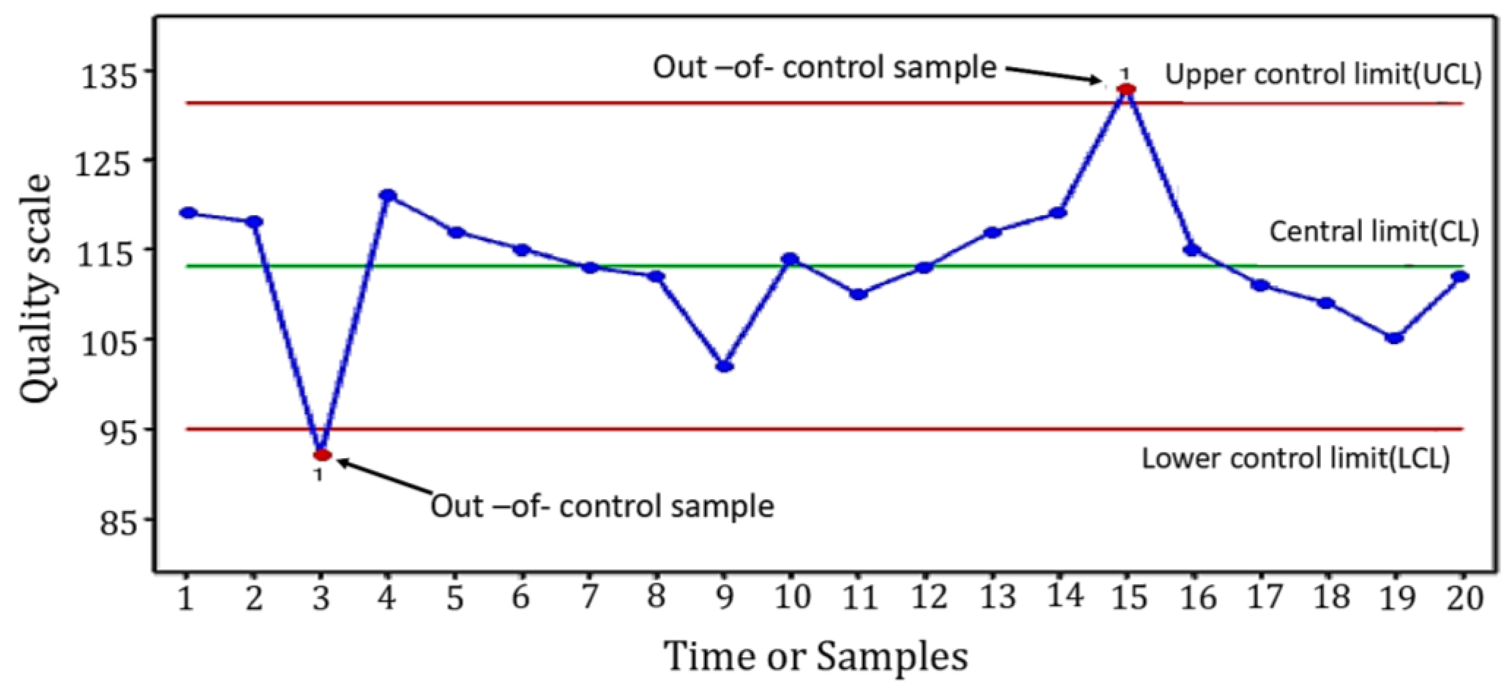
Statistical control charts are graphs applied to investigate whether a process varies over time. Therefore, the data are plotted in a sequence of time. Control charts consist of three lines representing the control area: the central line, upper line, and lower line. The central line of the control chart represents the central limit (CL) or mean, an upper line represents the upper control limits (UCL), and a lower line represents the lower control limits (LCL). These limits are computed from historical data based on the normal conditions of the process or machine. Performance is tested by comparing current data and its occurrence within these limits, which reveals whether the process variance is controlled, i.e., in-control or out-of-control, affected by special causes of variance [36]. Figure 4 displays a typical control chart. This chart description of a quality characteristic computed or measured from the number of samples or a time sequence. The x-axis represents the number of samples or time, and the y-axis represents the boundaries of the control region known as the 3-sigma control region. The chart shows the condition of the samples subject to control and their monitoring. The chart issues an alarm signal when any monitored sample exits the upper and lower control limits. Statistical control charts are classified into univariate and multivariate charts. Univariate charts monitor a single variable, such as the vibrations caused by the machines, the variation in temperature, relative humidity in the manufacturing plant, and fluctuations in electricity supply [37]. Many of these charts have been developed, such as Shewhart X-bar, Exponentially Weighted Moving Average (EWMA), and Cumulative Sum (CUSUM) schemes [36] (Chapter 9).
In this study, Shewhart X-bar and EWMA charts were chosen to monitor the variations of simulated vibration signals acquired from a dynamic model of a bevel gearbox. The basic principle and mathematical formulas for the above charts are explained in the following sections:

3.3.1. The Shewhart X-Bar Control Chart Principle

The Shewhart X-bar chart is one of the oldest statistical quality control charts and the first suggested scheme for testing the hypothesis. The American scientist Walter A. Shewhart first discovered it during the first half of the twentieth century [36]. The X-bar chart is widely used in statistical process control and is a helpful tool for detecting large shifts in the process mean [37]. An X-bar chart is used to monitor the mean of a process by collecting samples acquired from the process at certain times and subgroups ( n ) ranging between two and ten observations. The mean ( μ x ) of subgroups is calculated and shown as a “snap-shot” process in a given sample or time. The X-bar chart monitors the most recent data sample concerning the investigated process and overlooks any relevant information included in earlier samples. The control chart consists of three limits, namely the central limit (CL), the upper control limit (UCL), and the lower control limit (LCL), as explained in Equations (13)–(15) [36] (p. 185).
CL = μ x
UCL = μ x + K σ x
LCL = μ x K σ x
where, x represents the statistical parameter for measuring quality characteristics. μ m and σ x are the mean and standard deviation, respectively, whereas K represents the distance between the UCL and LCL from the CL of the controlled data. The value of K was first suggested as equal to 3 by Walter S. Shewhart, and hence, such control charts are known as Shewhart control charts [36].

3.3.2. Exponentially Weighted Moving Average Control Chart Principle

EWMA control chart is one of the statistical quality control chart types; it was first introduced by Roberts [38]. The EWMA chart effectively detects small shifts in the process mean because the EWMA chart considers all the previous and current data in the entire process history [39]. On the other hand, the CUSUM chart accumulates all relevant information from the historical data, giving equal weight to all process history observations. For this reason, the EWMA chart is much less sensitive to exceeding the normal assumption because it utilizes a weighted average of all previous and present observations compared to the CUSUM chart [36] (Chapter 9). According to the literature, EWMA is one of the most widely utilized charts for process monitoring because of its adaptability and sensitivity to small shifts. The chart is widely used in time series analysis and in many different disciplines by scientists and engineers to detect abnormalities [40]. The EWMA chart’s moving average is computed by multiplying the historical data by a weight that decays exponentially with time [41]. The following mathematical expression describes the EWMA decision statistic in Equation (16). The EWMA control chart mainly consists of three control limits: the upper control limit, the central limit, and the lower control limit, also known as the control area (3 sigma region). The UCL, CL, and LCL are set as in Equations (17)–(19).
E W M A t = λ x t + ( 1 λ ) E W M A t 1 if   t > 0
E W M A 0 = μ 0     if   t = 0
where the E W M A t represents the output for the observation statistics values, and x t is the value corresponding to the observation in the monitoring process in real-time. The E W M A t statistic value is initially dependent on the average of the normal data (healthy condition) to be equal to μ 0 .   λ is the smoothing constant, which ranges between 0 and 1 [36].
UCL = μ 0 + L σ λ ( 2 λ ) [ 1 ( 1 λ ) 2 i ]
C L = μ 0
LCL = μ 0 L σ λ ( 2 λ ) [ 1 ( 1 λ ) 2 i ]
where L is a multiplier of the EWMA standard deviation ( σ ) .

4. Results and Discussion

4.1. Numerical Simulation of Dynamic Behaviour

Considering an SBGS model shown in Section 2, vibration signals are simulated in healthy and faulty conditions. Its parameters are given in Table 2. The dynamic response of the SBGS is calculated using the Newmark problem-solving method, then gear mesh stiffness is introduced in the Equation (1) of system motion.
In this model, a local defect is created on the root of one tooth pinion of the 14 teeth. This defect exhibits as a crack caused by a repetitive reduction in the profile of mesh stiffness whenever the cracked tooth comes into contact with another tooth during the meshing process. Each level of tooth crack severity corresponds to a different level of mesh stiffness severity as shown in Figure 5, which can be described as follows: 1% decrease in mesh stiffness (crack level 1), 5% decrease in mesh stiffness (crack level 2), and 10% decrease in mesh stiffness (crack level 3). The crack defect has a period of 0.0454 s, corresponding to a frequency of 22 Hz.
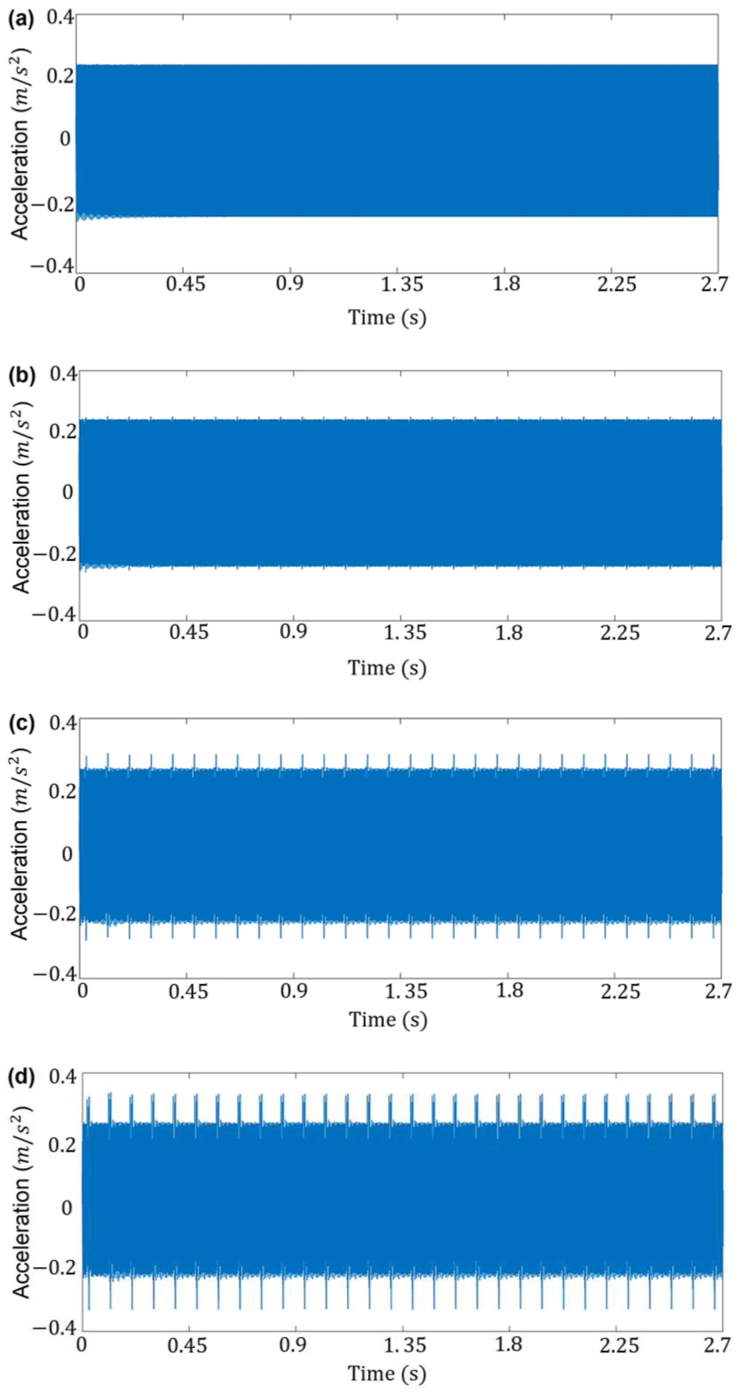
Assuming we take into account a sampling frequency of f s   = 30,800 Hz, a sampling time of T s = 3.24675 ×   10 5 s, and a number of samples (N = 84,000 samples), we obtain a total time of 2.7 s for each initial signal. Figure 6 represents the mesh stiffness function that was included in the vibration acceleration signals under the health conditions as well as the three different levels of crack defects.
To simulate the initial vibration signals of the working environment in real life, Gaussian noise was added using different ratios of noise variance ( σ 2 ), where the appropriate noise variance ratio equal to 0.001 was chosen because it gave the highest value of SNR as shown in Table 3. The noisy simulated acceleration signals under healthy and faulty conditions are shown in Figure 7.

4.2. Vibration Analysis Methods Results

4.2.1. Time-Domain Analysis Method

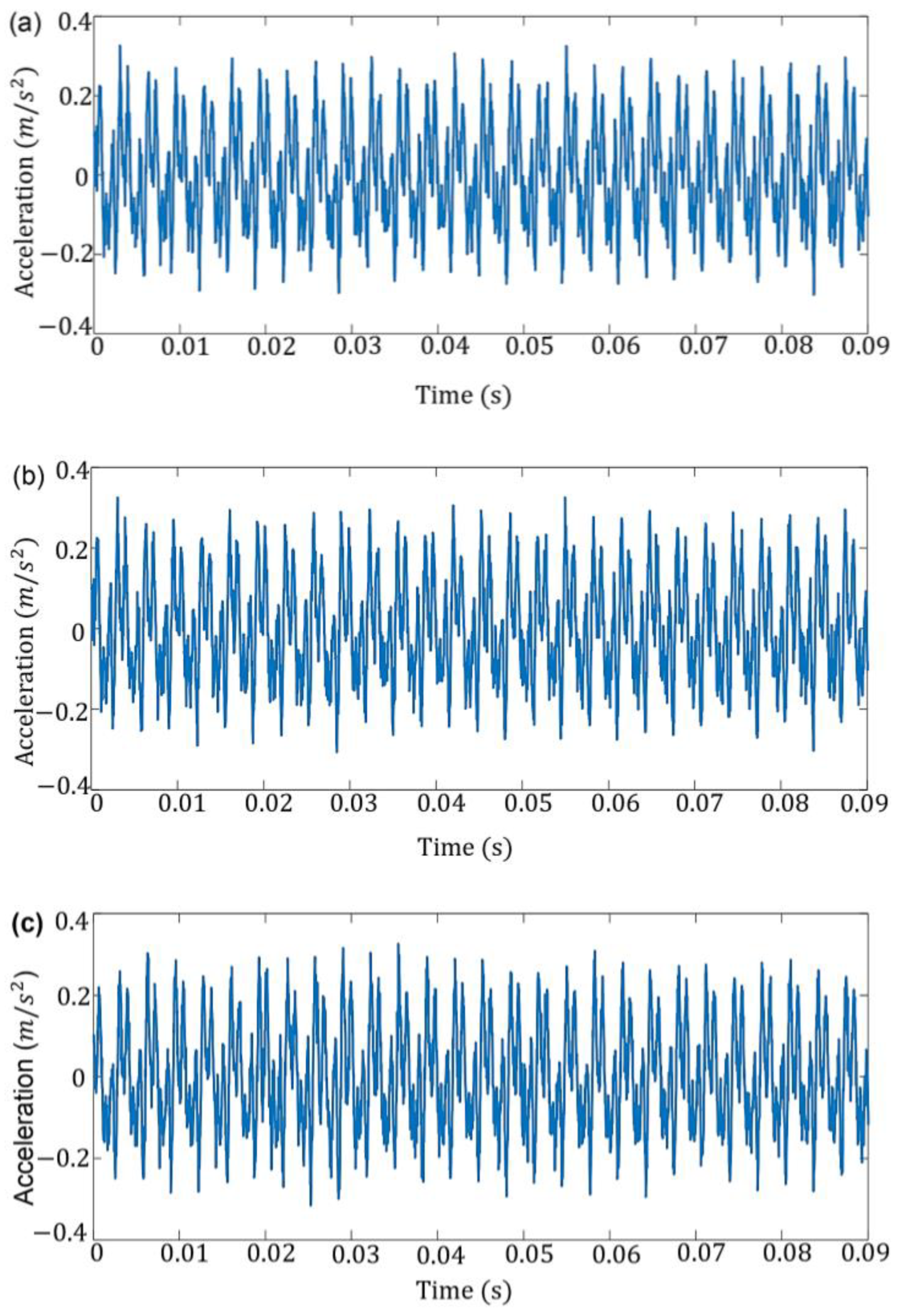
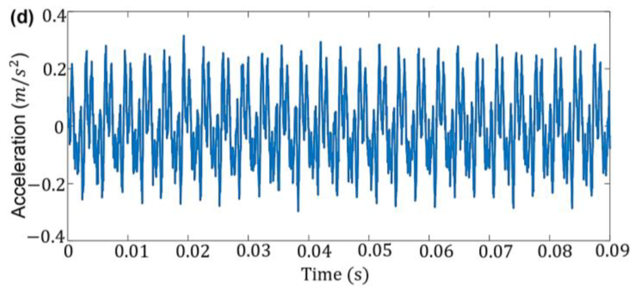
The time domain signal is analyzed to determine the diagnostic information to extract components of gear tooth failure. The crack fault components often appear in a time domain signal as periodic impulses that can be seen more clearly as the crack level increases [42]. As we explained earlier, the faults are simulated with small crack defect levels of 1, 2, and 3 produced by the repeated reduction in the gear mesh stiffness by levels 1%, 5%, and 10%, respectively, once per shaft revolution. Thus, the period between every two pulses equals the period of one shaft T 1 = 1 f 1 = 0.0454 s. Generally, short-period signals provide a clearer and more accurate visual insight into the fault signature than long-period signals. Therefore, vibration signals with a length of 2.7 s for the healthy and faulty states were divided into 30 windows as short-time signals. Each short-time signal represents the period between two fault-related pulses, a length of 0.09 s using a sampling time (Ts) equal to 3.24675 × 10⁻⁵ and the number of samples N = 2800. Figure 8 shows short-time acceleration signals representing two rotations of the pinion in the y-direction of the healthy and cracked gears. The time-short signals in Figure 8b–d, with crack levels caused by decreasing TVMS by 1%, 5%, and 10%, appear very similar to the healthy signal (without crack) in Figure 8a. These findings are consistent with the literature [42] on crack detection generated by reducing the mesh stiffness in spur gears by 2%, 6%, 18%, and 28%. As a result, the time-domain signal analysis did not provide any information about the appearance of a periodic vibration pulse or an increase in vibration amplitude that may indicate the appearance of a crack caused by the mesh stiffness influence.
For further analysis, the effect of mesh stiffness variation on the dynamic response of the gear system. One statistical indicator, the standard deviation (STD), was used. The STD, as a fault-sensitive feature, was extracted from the short-time signals and used to design and test the SPCC technique. Therefore, STD features values are calculated from each short-time signal by 30 values for each healthy and faulty signal using Equation (10). Figure 9 shows the resulting standard deviation (STD) values of the SBGS signals under the healthy case and three different crack levels. There is a clear overlap between the four cases, as appears in Figure 9. Thus, the increased crack levels on the vibration response of the meshing gears cannot be effectively determined by the dynamic statistical results of the STD. Therefore, we introduced a statistical process control charts (SPCC) approach using a Shewhart X-bar chart and EWMA chart based on STD features to diagnose the crack defect level.

4.2.2. Frequency-Domain Analysis Method

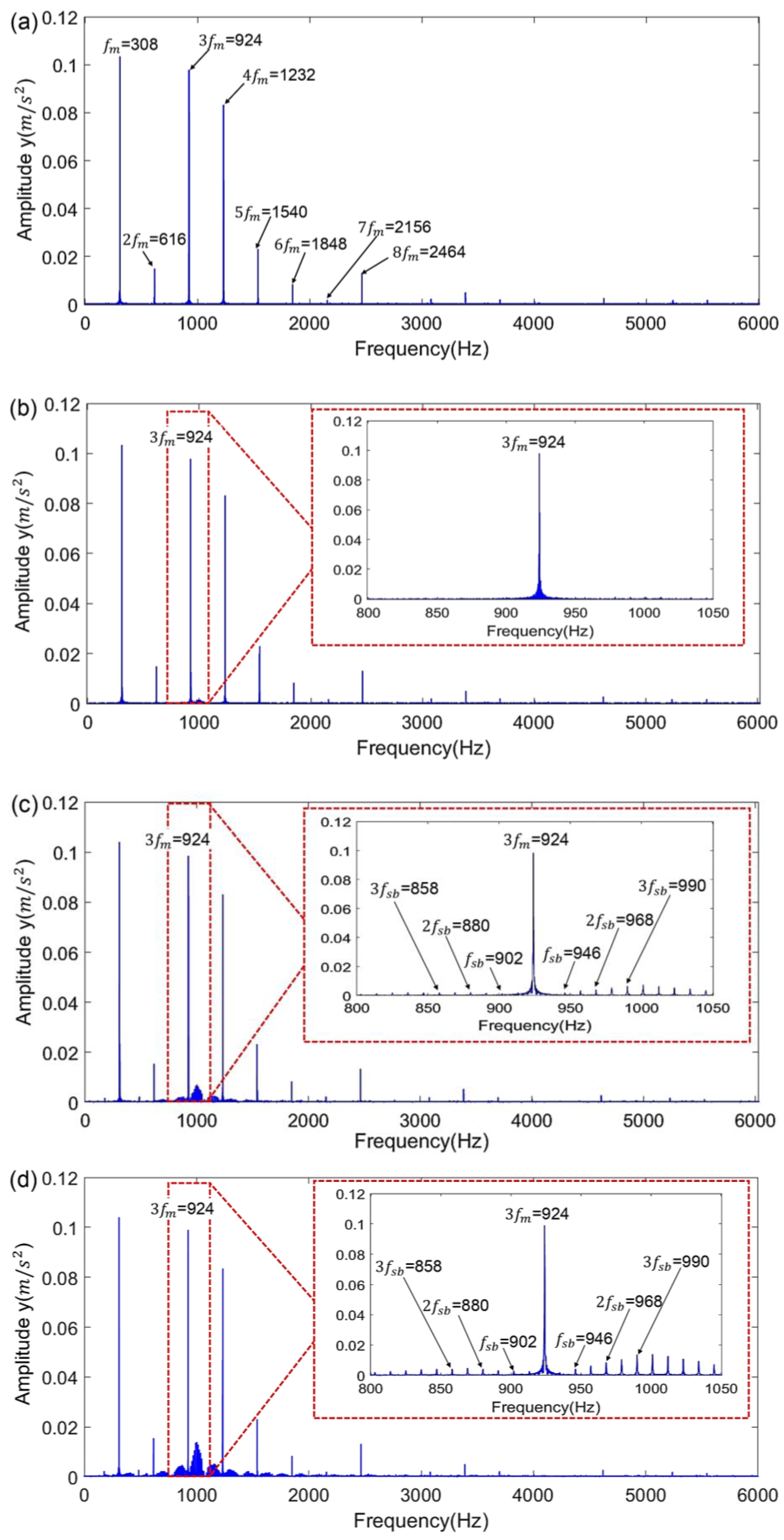
The FFT spectra were recorded of the SBGS vibration signal under healthy and faulty conditions. From Figure 10a, we can see that the gear mesh frequencies (fm = 308) and the harmonic frequencies (3fm, 4fm) are the largest in the spectra, as is evident by the dominance of their prominent peaks. After a crack tooth defect due to a 1% loss in mesh stiffness (Figure 10b), we can see no increase in the amplitude of the meshing frequency and the sidebands of the third harmonic frequency. The interval of the sideband frequency is the pinion rotation frequency (fr = 22 Hz). At the same time, we can see a slight increase in the amplitude of the sidebands around the third harmonic in Figure 10c,d with an increase in the level of a crack defect caused by a loss increase in the mesh stiffness at a ratio of 5% and 10%.

4.3. Designing Control Charts Results

As mentioned earlier, X-bar and EWMA charts are univariate; they adopt one variable to monitor the variation in the gear vibration signal. Therefore, the standard deviation was used as a statistical monitoring variable for the vibration signal changes.
As a first step for designing control charts based on STD features, the essential condition for selecting features must be met, requiring their distribution to be normal, a prerequisite of design SPCC threshold bounds (control limits) [36].
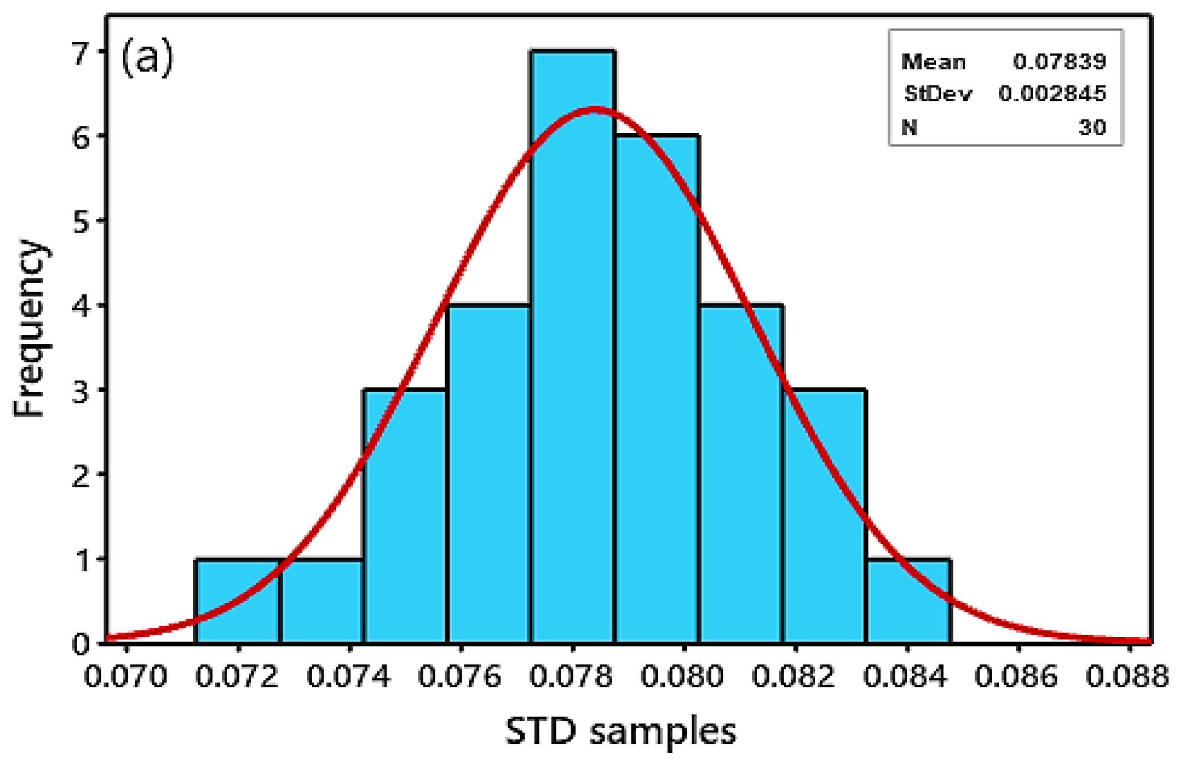
The condition of the normal distribution of the STD features based on the healthy pinion signal was verified by visual verification of the graphs of the Minitab 2019 statistical package, shown in Figure 11. The histogram was used to evaluate whether the distribution of the STD values of healthy pinion condition corresponded to the normal distribution, as shown in Figure 11a. The histogram is a bar graph tool that displays data in the same format as a probability density function. The graph’s horizontal axis represents the variable samples, and the vertical axis represents the frequency of the data. The histogram showed that the data distribution is bell-shaped, meaning the resulting STD feature for a healthy pinion state is normally distributed [36] (Chapter 3). Similarly, normal probability plots are very useful and often the first tool to appropriately determine the data distribution. In Figure 11b, a normal probability plot was used by drawing a probability line passing through the mean of the variable and the cumulative probability of 50%. The cumulative probability scale is displayed on the vertical axis of the plot, and the STD values are displayed on the horizontal axis. According to the probability plot, most data points are centered along the line of normal probability and normally distributed along this line. However, data points are generally not distributed if they have a curve shape. The histogram results and normal probability plot show that the STD feature satisfies the essential requirements for normal distribution data.
After the condition of normal distribution of the STD features is satisfied, the STD samples are extracted based on the health status of the gears, of which there are 30 values, and are transferred to the Minitab 2019 software. Then, the central limit (CL) of the control chart, representing the mean ( μ ) sum of the total for STD samples divided by the total number, is calculated to equal 0.07839 and a multiplier of the EWMA standard deviation ( σ ) to equal 0.002845. Next, the design parameters of the control limits of each of the two schemes are determined as follows: for the design of the X-bar chart, the K = 3 parameter is specified. This choice of the K value makes about 99% of the observed data fall within the control area (3 sigma region) [33,36].
Along the same lines, in the EWMA design, the parameters are determined by λ = 0.2 and L = 3. It has been demonstrated that λ-values lie between the range 0 < λ <1; generally, choosing smaller λ values increases the sensitivity of the EWMA to detect small shifts [23,38]. Moreover, selecting small values of λ and L can provide a suitable balance between data for historical and current observations in the EWMA. Finally, the upper control limits (UCL) and lower control limits (LCL) are calculated for the X-bar chart by Equations (13)–(15) and the EWMA chart using by Equations (16) and (19).
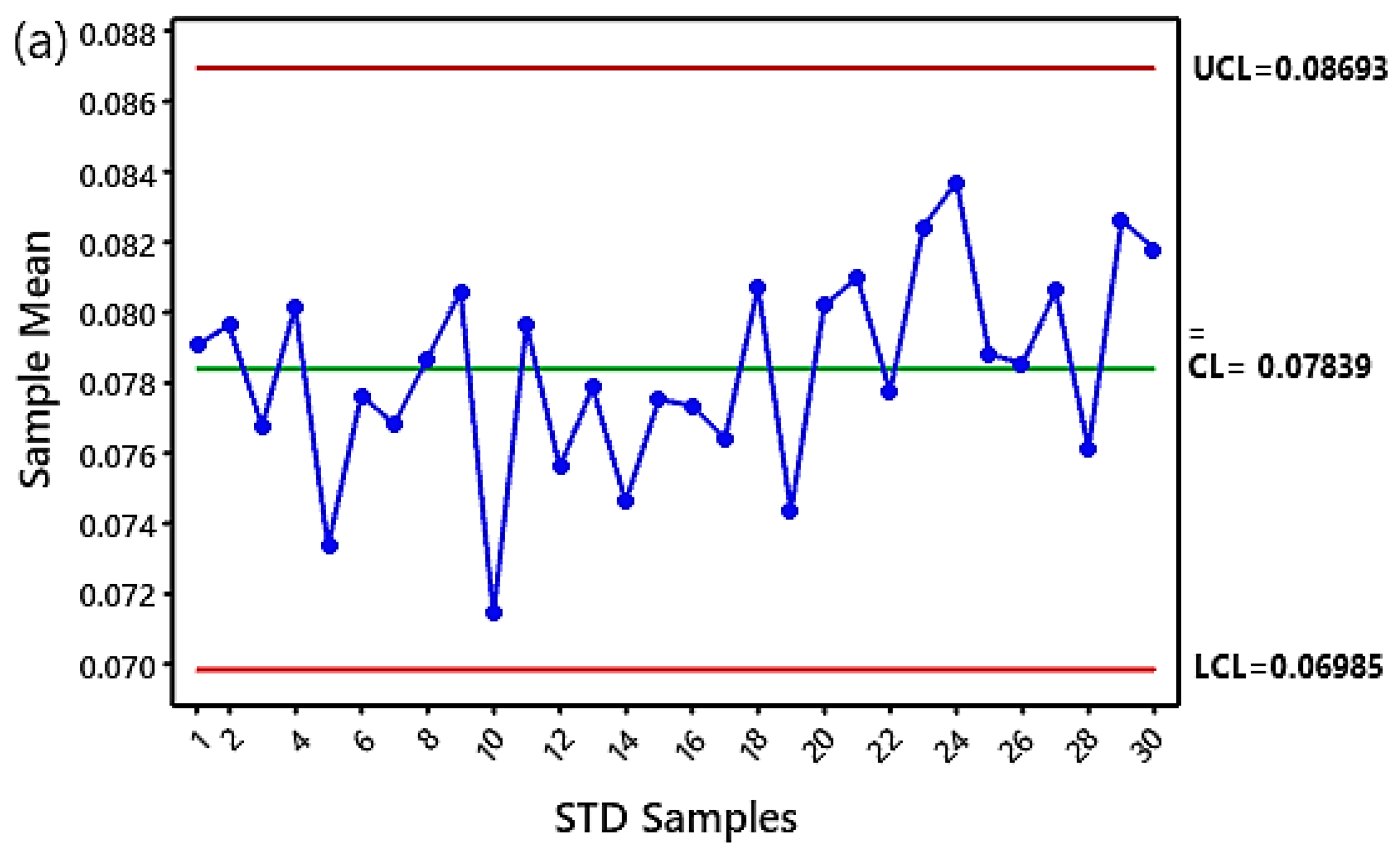
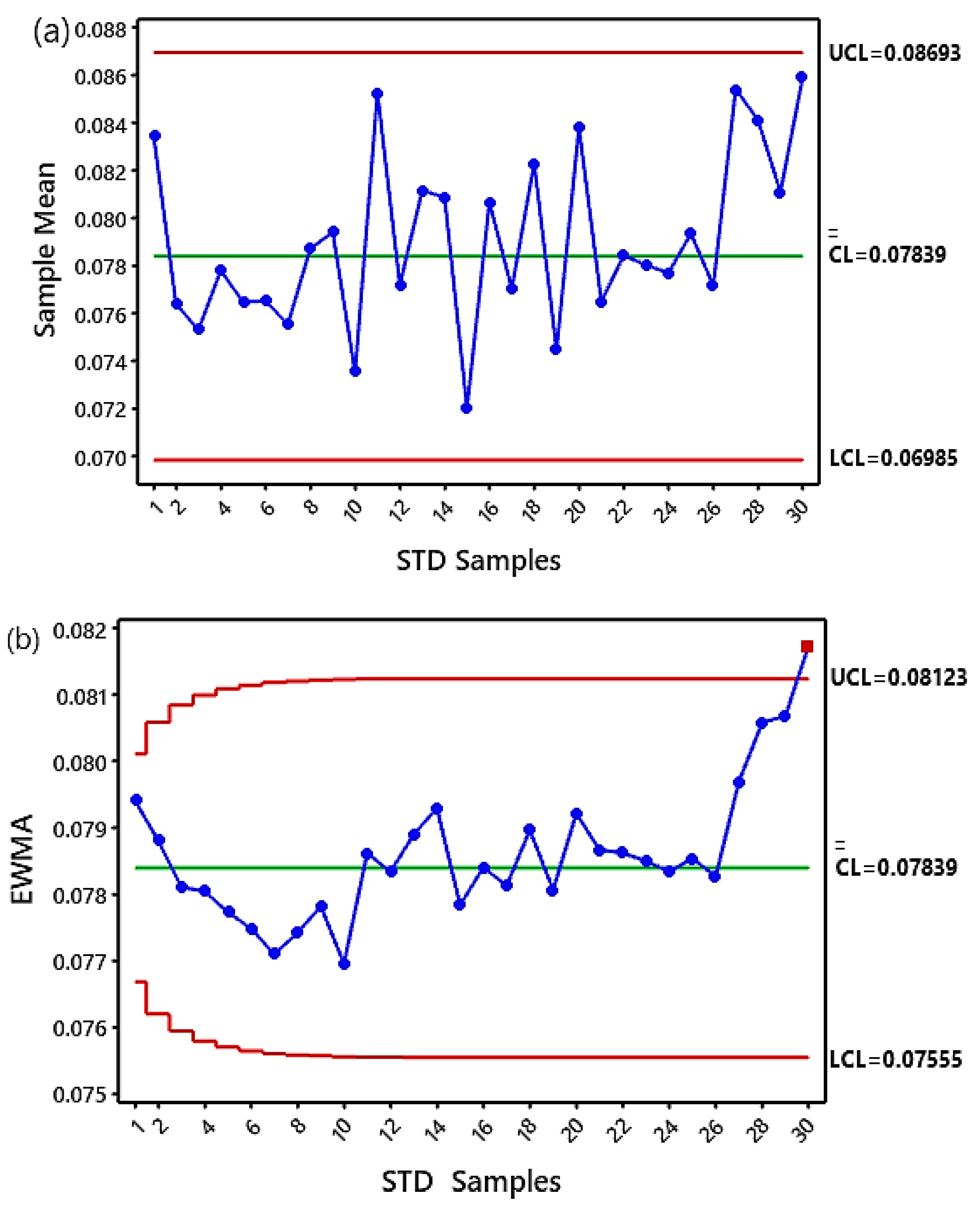
Following providing the necessary information, the design phase of the two control schemes is completed using the statistical Minitab19 software. Figure 12 shows the X-bar and EWMA control charts for monitoring the time acceleration signals of a pinion under normal conditions. It is seen that the average amplitude of all controlled statistical features lies within the control region. As a result, these control charts show how the normal gear system works. Moreover, the charts provide a graphical display of the STD samples within the control limits, which reflects the stability status of the system under healthy operating conditions and any sudden shifts that can occur concurrently.

4.4. Testing Control Charts Results

The testing phase begins after the design phase of the control system has been examined using quality schemes based on the health conditions of the gears. As a first step to implementing this, the standard deviation (STD) samples for each faulty signal are moved to the Minitab 19 software. Next, the same upper control limits (UCL) and lower control limits (LCL) are used for the charts in the healthy state. The same procedure is repeated to test three defect levels. It is widely known that when control charts are used, two types of errors occur: Type-I and Type-II.
To compare the test performances of the control system by X-bar and EWMA charts in detecting crack faults, we measured the following two benchmarks: (1) whether a fault level can be detected more quickly and (2) the types of errors that can occur when control charts are used. In this study, we classified Type-I errors as those in which the gearbox is healthy (without fault), but its monitored data fall outside the control area. In Type-II errors, the gearbox is faulty, but controlled data do not fall outside the control area. Indeed, Type-II errors were easier to detect in this study, as the fault signal was known. In contrast, Type-I errors did not occur, as no event outside the control limits was recorded for a gearbox under healthy conditions (as explained in Figure 12). For this reason, we focused on Type-II errors. The SPCC test results are discussed based on the three crack cases shown below.

4.4.1. The Crack of Level 1 (1% Loss in Mesh Stiffness)

In this case study, shown in Figure 13, the testing data shows a defect at the root of one of the teeth in the pinion. Figure 13a illustrates the fault monitoring process using the X-bar chart, which was utterly unable to detect the fault; thus, it resulted in Type II errors. The reason is that X-bar fault detection metrics only take information about new data samples into the decision-making process and ignore other information, making these metrics ineffective at detecting minimal shifts.
On the contrary, the performance of the EWMA shows successful results in the control process in Figure 13b, which is exhibited by exceeding one sample for the upper control limits (out of control) at sample 30. As a result, the EWMA chart could effectively detect the level 1 fault without triggering any false alarms because it uses both historical and current data in its monitoring process.

4.4.2. The Crack of Level 2 (5% Loss in Mesh Stiffness)

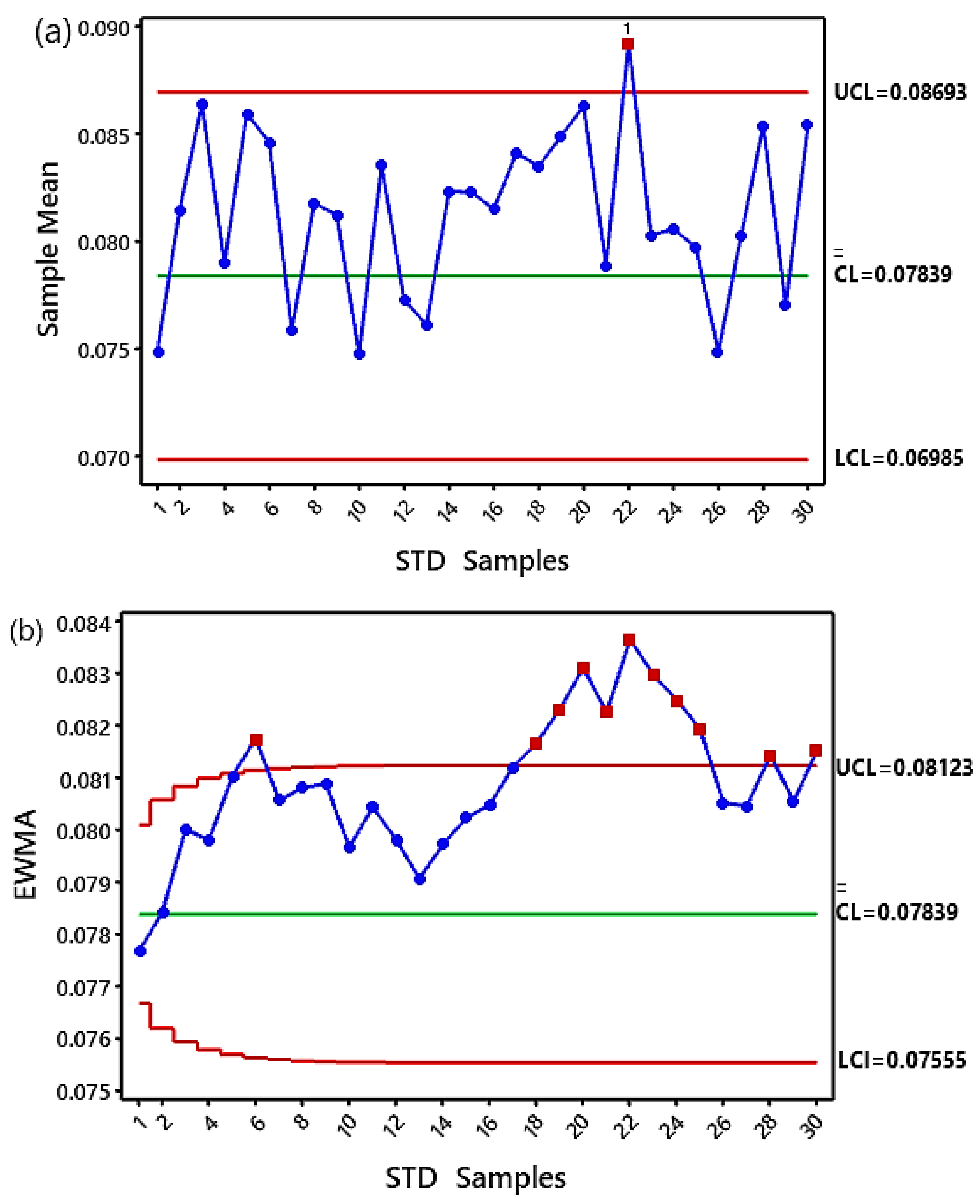
In this case study, a tooth crack failure was simulated with an increasing reduction of 5% in mesh stiffness to test the ability of the schemes to detect the fault. Figure 14 illustrates the results obtained by comparing the two monitoring charts. Figure 14a shows that as the level of crack defect increases, the performance of the X-bar chart shows a slight improvement in crack detection. This development is represented by the red dot in Figure 14a, which denotes that the STD feature (sample no. 22) beyond is out-of-control, which indicates that the beginning of a crack has occurred. This STD feature is visible in the associated period of two defect pulses (2Td = 0.091 s × 22), which represents the time at 2 s of the total signal time of 2.7 s.
In contrast, EWMA showed substantial superiority in detecting defect level 2. It is illustrated by the rapidity with which the fault was identified, beginning with the departure of the STD feature (sample no. 6) from the control region, as shown in Figure 14b. In addition, the EWMA chart proved that the decrease in gear mesh stiffness led to increases in the crack level confirmed by the increase in out-of-control samples, estimated at 11 samples. Furthermore, the speed of EWMA in defect detection is represented by the STD feature period associated with two defect pulses (2Td = 0.091s × 6), which represents the time in 0.54 s out of a total signal time of 2.7 s.

4.4.3. The Crack of Level 3 (10% Loss in Mesh Stiffness)

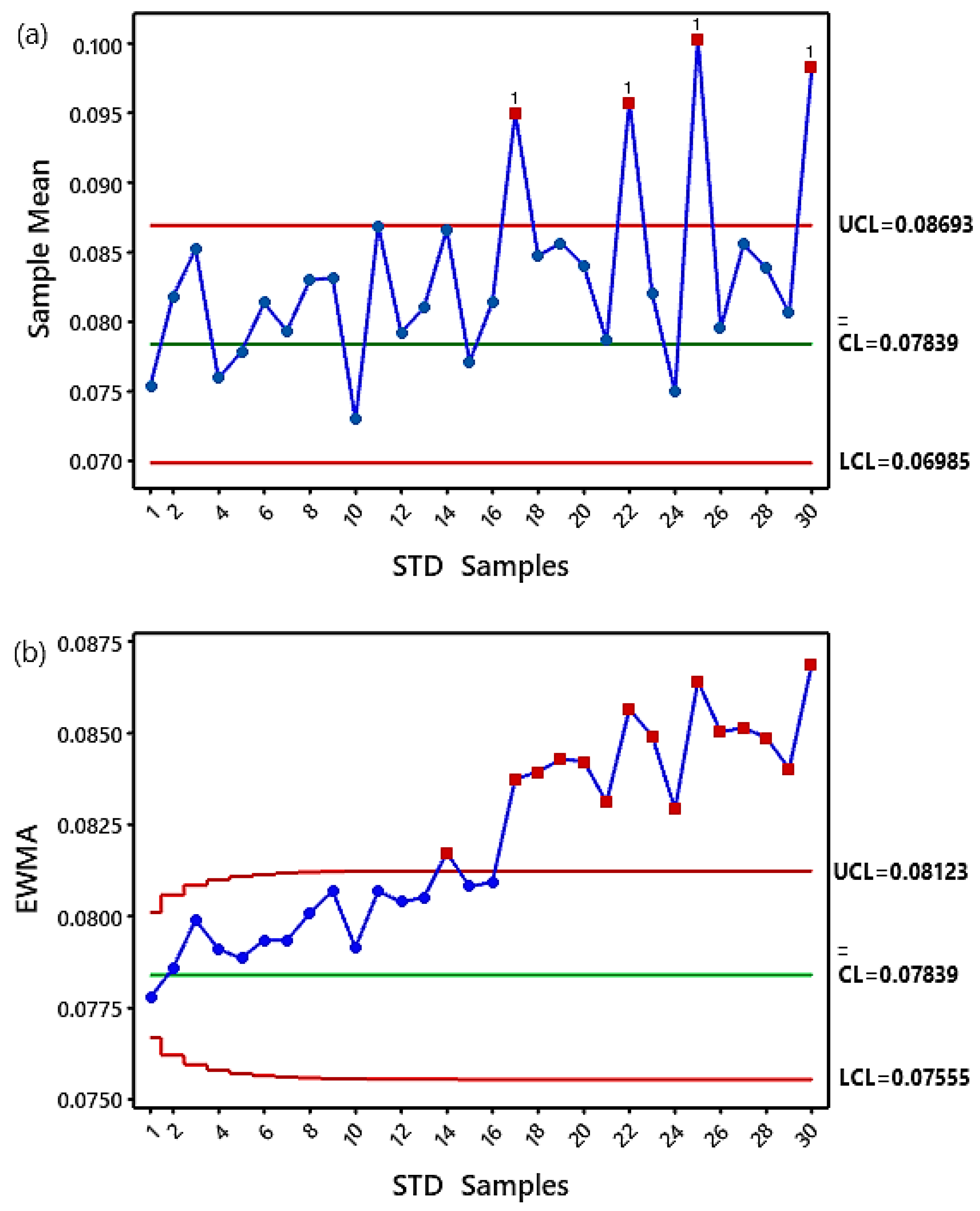
In this case study, a defect level 3 was introduced into the tooth root of the pinion. The statistics for the control charts for this case are displayed in Figure 15. The X-bar chart demonstrates in Figure 15a the possibility of detecting defects through the samples outside the upper control limits. However, it could recognize this defect for specific periods of the process control, as evidenced by the number of samples within the control region.
On the contrary, the EWMA chart has been demonstrated to be outstanding in early detection and defect recognition throughout the monitoring period. The monitoring process appeared completely out of control after sample14 became uncontrolled samples, i.e., the occurrence of a gear crack, as shown in Figure 15b.
This result makes perfect sense because the EWMA chart effectively detects small shifts. Consequently, the X-bar chart’s usual control area limits were higher than the EWMA limits. Therefore, medium-level defects can easily exceed the EWMA threshold but not the X-bar threshold, which makes the EWMA chart more sensitive than the X-bar for this type of fault with small levels. As a result, these graphs indicate the strong association between increasing levels of defect and changes in the pattern of the linear acceleration of the defective tooth through the number of out-of-control samples.
Table 4 shows the performance results of the control charts for detecting crack faults, where the control process by the EWMA chart has been even more accurate and clear than the X-bar chart.
By comparing the results of the proposed SPCC technique with previous studies [15,42,43], it can be concluded that crack fault detection resulting from repeated reductions in TVMS of 1%, 5%, and 10% was not reported in [15,42,43]. For instance, the results in [15] indicated the detection of levels of tooth fracture in the bevel gears at levels ranging from 10% to 60% through the development of statistical indicators of the time-domain signals. According to the results in [42], tooth cracks were not detected at levels (2%, 6%, 18%, and 28%), whereas detected crack levels ranged from 42% to 78% using the statistical features of the time domain analysis. In contrast, the outcomes reported in [43] identify tooth crack levels at 48.38%.

5. Conclusions

In this paper, we investigate a new approach to gear crack detection by applying vibration analysis techniques and statistical process control charts (SPCC) based on simulated vibration signals from a dynamic model of a spiral bevel gear system (SBGS) running under stationary conditions. The proposed approach was evaluated using the methods of time domain analysis, frequency domain analysis, univariate statistical control charts, such as the Shewhart X-bar chart, and an exponentially weighted moving average (EWMA) chart. This approach includes the procedures of time-vibration signal analysis, analysis of FFT spectra, implementation of design and testing stages of control charts, and comparison of their performance to detect the crack fault in one of the teeth of the pinion with different defect levels: 1, 2, and 3, caused by a repeated decrease in gear mesh stiffness at percentages of 1%, 5%, and 10%, respectively. The conclusions can be stated as follows:
  • Gaussian noise was added for initial acceleration vibration signals using different ratios of noise variance of 0.001, 0.002, and 0.003, respectively, to simulate them in real life. Then, the suitable noise level was chosen based on the highest signal-to-noise ratio (SNR);
  • Vibration analysis methods, both time-domain and frequency-domain techniques, were applied to process signals and identify failing components. Time domain analysis of short-time signals revealed no failure components, such as a periodic pulse, as an indicator of the onset of crack occurrence and deterioration of its propagation levels. In contrast, one of the time domain features, the standard deviation (STD) feature, was extracted and calculated as a fault-sensitive statistical feature to be used in designing and testing an SPCC approach;
Besides, FFT spectra did not reveal the presence of any sideband frequency at crack defect level 1, resulting from a 1% decrease in mesh stiffness. Meanwhile, FFT spectra revealed a slight increase in the amplitude of the sideband frequency of the third harmonic with defect levels 2 and 3 due to the increased rate of repeated reduction in mesh stiffness by 5% and 10% as an alarm sign of the crack propagation. Thus, vibration analysis methods do not provide precise results for diagnosing micro-crack levels.
3.
Shewhart X-bar and EWMA univariate statistical control charts were designed using a time domain feature known as standard deviation (STD). Listed below are the outcomes that the SPCC was able to achieve;
  • The control chart results of the simulated vibration acceleration signals showed a strong relationship between the increase in the control chart limits (UCL, LCL) and the repeated reduction increase in time-varying meshing stiffness (TVMS)at 1%,5%, and 10% for crack detection;
  • The EWMA chart’s performance proved superior to vibration analysis techniques in quickly detecting all levels of crack through a clear visual vision by increasing the number of STD feature samples outside the control chart limits;
  • The EWMA chart showed better results than the X-bar chart. In two ways: firstly, the EWMA chart detected all small crack levels early stage, as evidenced by sequencing the number of STD feature samples outside the upper control limits (UCL), and secondly, the EWMA chart did not record any Type I or Type II errors;
  • Furthermore, the advantage of the SPCC approach is that it is implemented using only system health status data, which are appropriate and applicable, especially in cases where there is a lack of defective status data. On the contrary, the main disadvantage of SPCC is that they can detect damage without locating it;
According to this research’s findings, the study’s main objective was to investigate alternative methods of diagnosing small crack levels. When compared to the studies [15,42,43], which detects a large crack level of 48.38%, detecting a large crack level could not be more beneficial from a practical point of view because it can be seen visually. In addition, the tooth will break with such a large crack because gearboxes usually operate under heavy loads.
It is worth mentioning that in some published papers [21,22], new methods have been used to diagnose crack defects due to the effect of mesh stiffness variation in SBGS under non-stationary operating conditions (variable speed and load). The research focus of this paper was to discuss the presentation of the results of the proposed method for simulated tooth crack detection at small levels instead of large levels [15,42,43]. The above factors were not taken into consideration in this paper. Therefore, in our future work, these factors will be taken into account, as well as experimental data, for more evaluation and investigation by the proposed SPCC approach.

Author Contributions

All authors contributed to the main idea of this paper. Conceptualization, R.M.J. and F.C.; methodology, R.M.J.; software, R.M.J. and M.H. (Maroua Haddar); validation, R.M.J., F.C. and M.H. (Maroua Haddar); formal analysis, F.C., M.H. (Mohamed Haddar), M.H. (Maroua Haddar) and R.M.J.; investigation, R.M.J., F.C. and M.H. (Maroua Haddar); data curation, F.C. and R.M.J.; writing—original draft preparation, R.M.J.; writing—review and editing, F.C., M.H. (Maroua Haddar) and R.M.J.; visualization, R.M.J., F.C. and M.H. (Maroua Haddar); supervision, F.C., M.H. (Mohamed Haddar) and M.H. (Maroua Haddar). All authors have read and agreed to the published version of the manuscript.

Funding

This research received no external funding.

Data Availability Statement

The authors will make available the data used in this work if requested by email: [email protected] and [email protected].

Conflicts of Interest

The authors declare no conflict of interest.

References

  1. Motahar, H.; Samani, F.S.; Molaie, M. Nonlinear vibration of the bevel gear with teeth profile modification. Nonlinear Dyn. 2016, 83, 1875–1884. [Google Scholar] [CrossRef]
  2. Chaari, F.; Fakhfakh, T.; Haddar, M. Analytical modelling of spur gear tooth crack and influence on gearmesh stiffness. Eur. J. Mech. A/Solids 2009, 28, 461–468. [Google Scholar] [CrossRef]
  3. Mohammed, S.A.; Ghazaly, N.M.; Abdo, J. Fault Diagnosis of Crack on Gearbox Using Vibration-Based Approaches. Symmetry 2022, 14, 417. [Google Scholar] [CrossRef]
  4. Ma, H.; Song, R.; Pang, X.; Wen, B. Time-varying mesh stiffness calculation of cracked spur gears. Eng. Fail. Anal. 2014, 44, 179–194. [Google Scholar] [CrossRef]
  5. Ma, H.; Zeng, J.; Feng, R.; Pang, X.; Wang, Q.; Wen, B. Review on dynamics of cracked gear systems. Eng. Fail. Anal. 2015, 55, 224–245. [Google Scholar] [CrossRef]
  6. Mohammed, O.D.; Rantatalo, M. Gear fault models and dynamics-based modelling for gear fault detection—A review. Eng. Fail. Anal. 2020, 117, 104798. [Google Scholar] [CrossRef]
  7. Chen, Z.; Shao, Y. Dynamic simulation of spur gear with tooth root crack propagating along tooth width and crack depth. Eng. Fail. Anal. 2011, 18, 2149–2164. [Google Scholar] [CrossRef]
  8. Mohammed, O.D.; Rantatalo, M.; Aidanpää, J.O.; Kumar, U. Vibration signal analysis for gear fault diagnosis with various crack progression scenarios. Mech. Syst. Signal Process. 2013, 41, 176–195. [Google Scholar] [CrossRef]
  9. Mohammed, O.D.; Rantatalo, M. Dynamic response and time-frequency analysis for gear tooth crack detection. Mech. Syst. Signal Process. 2016, 66–67, 612–624. [Google Scholar] [CrossRef]
  10. Jiang, H.; Liu, F. Analytical models of mesh stiffness for cracked spur gears considering gear body deflection and dynamic simulation. Meccanica 2019, 54, 1889–1909. [Google Scholar] [CrossRef]
  11. Wang, L.; Shao, Y. Fault mode analysis and detection for gear tooth crack during its propagating process based on dynamic simulation method. Eng. Fail. Anal. 2017, 71, 166–178. [Google Scholar] [CrossRef]
  12. Yassine, D.; Ahmed, H.; Lassaad, W.; Mohamed, H. Effects of gear mesh fluctuation and defaults on the dynamic behavior of two-stage straight bevel system. Mech. Mach. Theory 2014, 82, 71–86. [Google Scholar] [CrossRef]
  13. Figlus, T.; Wilk, A. Application of analysis of envelope’s spectrum for gearbox diagnosing. Int. Rev. Mech. Eng. 2012, 6, 1350–1355. [Google Scholar]
  14. Hu, C.; Smith, W.A.; Randall, R.B.; Peng, Z. Development of a gear vibration indicator and its application in gear wear monitoring. Mech. Syst. Signal Process. 2016, 76–77, 319–336. [Google Scholar] [CrossRef]
  15. Yang, D.; Chen, L.; Jiang, L.; Wang, P.; Tao, J. Research on the influence of time-varying excitation on vibration characteristics of the spiral bevel geared transmission system with broken teeth. Shock Vib. 2021, 1–10. [Google Scholar] [CrossRef]
  16. Figlus, T. A method for diagnosing gearboxes of means of transport using multi-stage filtering and entropy. Entropy 2019, 21, 441. [Google Scholar] [CrossRef] [PubMed] [Green Version]
  17. Dewangan, P.; Ramteke, D.S.; Parey, A. Smart Monitoring of Rotating Machinery for Industry 4.0. In Model Based Fault Diagnosis in Bevel Gearbox; Chaari, F., Chiementin, X., Zimroz, R., Bolaers, F., Haddar, M., Eds.; Springer Nature: Cham, Switzerland, 2022; pp. 117–133. ISBN 978-3-030-79518-4/978-3-030-79519-1. [Google Scholar]
  18. Han, H.; Ma, H.; Wang, H.; Zhu, J.; Li, Z.; Liu, Z. Dynamic Simulation of Cracked Spiral Bevel Gear Pair Considering Assembly Errors. Machines 2022, 10, 929. [Google Scholar] [CrossRef]
  19. Mauricio, A.; Wang, W.; Antoni, J.; Gryllias, K. Advanced signal processing techniques for helicopter’s gearbox monitoring. J. Phys. Conf. Ser. 2021, 1909, 012043. [Google Scholar] [CrossRef]
  20. Karray, M.; Chaari, F.; Khabou, M.T.; Haddar, M. Dynamic analysis of bevel gear in presence of local damage in nonstationary operating conditions. In Design and Modeling of Mechanical Systems—III; Lecture Notes in Mechanical Engineering; Springer: Cham, Switzerland, 2018; pp. 325–330. [Google Scholar] [CrossRef]
  21. Ziani, R.; Hammami, A.; Chaari, F.; Felkaoui, A.; Haddar, M. Gear fault diagnosis under non-stationary operating mode based on EMD, TKEO, and Shock Detector. Comptes Rendus—Mec. 2019, 347, 663–675. [Google Scholar] [CrossRef]
  22. Chaari, F.; Schmidt, S.; Hammami, A.; Heyns, P.S.; Haddar, M. Smart Monitoring of Rotating Machinery for Industry 4.0. In On the Use of Jerk for Condition Monitoring of Gearboxes in Non-Stationary Operations; Chaari, F., Chiementin, X., Zimroz, R., Bolaers, F., Haddar, M., Eds.; Springer Nature: Cham, Switzerland, 2022; ISBN 9783030795184. [Google Scholar]
  23. Zhu, H.; Chen, W.; Zhu, R.; Gao, J.; Liao, M. Modelling and Dynamic Analysis of the Spiral Bevel Gear-Shaft-Bearing-Gearbox Coupling System. Math. Probl. Eng. 2019, 2019, 9065215. [Google Scholar] [CrossRef]
  24. Peng, D.; Smith, W.A.; Borghesani, P.; Randall, R.B.; Peng, Z. Comprehensive planet gear diagnostics: Use of transmission error and mesh phasing to distinguish localised fault types and identify faulty gears. Mech. Syst. Signal Process. 2019, 127, 531–550. [Google Scholar] [CrossRef]
  25. Cao, W.; Pu, W.; Wang, J. Tribo-dynamic model and fatigue life analysis of spiral bevel gears. Eur. J. Mech. A/Solids 2019, 74, 124–138. [Google Scholar] [CrossRef]
  26. Molaie, M.; Samani, F.S.; Pellicano, F. Spiral Bevel Gears Nonlinear Vibration Having Radial and Axial Misalignments Effects. Vibration 2021, 4, 666–678. [Google Scholar] [CrossRef]
  27. Lal, H.; Kane, P.V. Gearbox Fault Detection Using Exponentially Weighted Moving Average Control Charts. In Machines, Mechanism and Robotics; Badodkar, D., Dwarakanath, T., Eds.; Lecture Notes in Mechanical Engineering; Springer: Singapore, 2019. [Google Scholar] [CrossRef]
  28. Maraş, S.; Arslan, H.; Birgören, B. Detection of Gear Wear and Faults in Spur Gear Systems Using Statistical Parameters and Univariate Statistical Process Control Charts. Arab. J. Sci. Eng. 2021, 46, 12221–12234. [Google Scholar] [CrossRef]
  29. Peng, T. Coupled Multi-Body Dynamic and Vibration Analysis of Hypoid and Bevel Geared Rotor System. Ph.D. Thesis, University of Cincinnati, Cincinnati, OH, USA, 2010. [Google Scholar]
  30. Karray, M.; Chaari, F.; Viadero, F.; del Rincon, A.F.; Haddar, M. Dynamic Response of Single Stage Bevel Gear Transmission in Presence of Local Damage. Mech. Mach. Sci. 2013, 7, 337–345. [Google Scholar] [CrossRef] [Green Version]
  31. Makovoz, D. Noise variance estimation in signal processing. In Proceedings of the 2006 IEEE International Symposium on Signal Processing and Information Technology, Vancouver, BC, Canada, 28–30 August 2006; pp. 364–369. [Google Scholar] [CrossRef] [Green Version]
  32. Fan, W.; Zhou, Q.; Li, J.; Zhu, Z. A Wavelet-Based Statistical Approach for Monitoring and Diagnosis of Compound Faults with Application to Rolling Bearings. IEEE Trans. Autom. Sci. Eng. 2018, 15, 1563–1572. [Google Scholar] [CrossRef]
  33. Jaber, A.A.; Bicker, R. Industrial robot fault detection based on statistical control chart. Am. J. Eng. Appl. Sci. 2016, 9, 251–263. [Google Scholar] [CrossRef] [Green Version]
  34. Jawad, S.M.; Jaber, A.A. Rolling Bearing Fault Detection Based on Vibration Signal Analysis and Cumulative Sum Control Chart. FME Trans. 2021, 49, 684–695. [Google Scholar] [CrossRef]
  35. Scheffer, C.; Girdhar, P. Practical Machinery Vibration Analysis and Predictive Maintenance; Elsevier: Amsterdam, The Netherlands, 2004; ISBN 0080480225. [Google Scholar]
  36. Montgomery, D.C. Introduction to Statistical Quality Control, 6th ed.; John Wiley & Sons, Inc.: Hoboken, NJ, USA, 2009; ISBN 9780470169926. [Google Scholar]
  37. Selvamuthu, D.; Das, D. Introduction to Statistical Methods, Design of Experiments and Statistical Quality Control; Springer Nature: Singapore; Singapore Pte Ltd.: Singapore, 2018; ISBN 9789811317361. [Google Scholar]
  38. Roberts, S.W. Control Chart Tests Based on Geometric Moving Averages. Technometrics 2000, 42, 97–101. [Google Scholar] [CrossRef]
  39. Hynek, M.; Smetanová, D.; Stejskal, D.; Zvárová, J. Exponentially weighted moving average chart as a suitable tool for nuchal translucency quality review. Prenat. Diagn. 2014, 34, 367–376. [Google Scholar] [CrossRef]
  40. Morton, A.P.; Whitby, M.; McLaws, M.; Dobson, A.; McElwain, S.; Looke, D.; Stackelroth, J.; Sartor, A. The application of statistical process control charts to the detection and monitoring of hospital-acquired infections. J. Qual. Clin. Pract. 2001, 21, 112–117. [Google Scholar] [CrossRef] [PubMed]
  41. Montgomery, D.C.; Runger, G.C. Applied Statistics and Probability for Engineers; John Wiley & Sons, Inc.: Hoboken, NJ, USA, 2010; ISBN 0470053046. [Google Scholar]
  42. Wu, S.; Zuo, M.J.; Parey, A. Simulation of spur gear dynamics and estimation of fault growth. J. Sound Vib. 2008, 317, 608–624. [Google Scholar] [CrossRef]
  43. Yang, L.; Wang, L.; Yu, W.; Shao, Y. Investigation of tooth crack opening state on time varying meshing stiffness and dynamic response of spur gear pair. Eng. Fail. Anal. 2021, 121, 105181. [Google Scholar] [CrossRef]
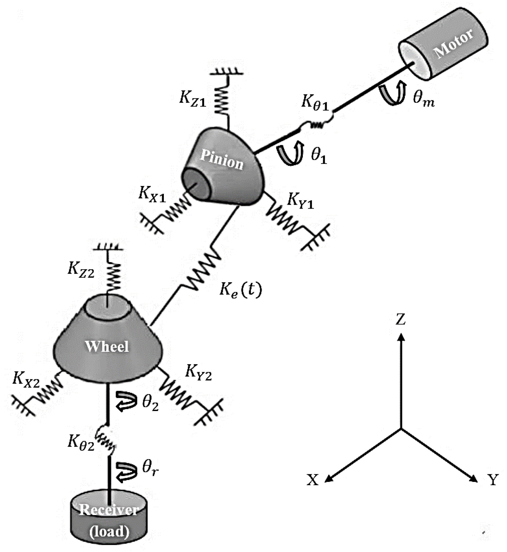
Figure 1. Dynamic model of a single-stage bevel gear system (10 DOF).
Machines 11 00312 g001
Figure 2. Time evolution of the gear mesh stiffness.
Machines 11 00312 g002
Figure 3. Flowchart of the proposed methodology framework.
Machines 11 00312 g003
Figure 4. Outline of a control chart.
Machines 11 00312 g004
Figure 5. Mesh stiffness, Ke(t) at different reduction cases: (a) case 1: no reduction, healthy, (b) case 2: 1% reduction in mesh stiffness, (c) case 3: 5 % reduction in mesh stiffness, and (d) case 4: 10% reduction in mesh stiffness.
Machines 11 00312 g005aMachines 11 00312 g005b
Figure 6. Initial simulation acceleration signals for four states: (a) healthy state, (b) crack level 1, (c) crack level 2, and (d) crack level 3.
Machines 11 00312 g006
Figure 7. Noisy simulation acceleration signals for four states: (a) healthy state, (b) crack level 1, (c) crack level 2, and (d) crack level 3.
Machines 11 00312 g007
Figure 8. Acceleration signals for each two rotations of the shaft at pinion rotation: (a) health state, (b) crack level 1, (c) crack level 2, and (d) crack level 3.
Machines 11 00312 g008aMachines 11 00312 g008b
Figure 9. Standard deviation (STD) statistical values extracted from the SBGS acceleration signals under healthy and faulty conditions.
Machines 11 00312 g009
Figure 10. FFT spectrum analysis for pinion signals cases (a) health state, (b) crack level 1, (c) crack level 2, and (d) crack level 3.
Machines 11 00312 g010
Figure 11. Normal distribution displays for the STD feature using (a) histogram and (b) normal probability plot.
Machines 11 00312 g011aMachines 11 00312 g011b
Figure 12. Univariate statistical control charts for the healthy pinion state (a) X-bar chart and (b) EWMA chart.
Machines 11 00312 g012aMachines 11 00312 g012b
Figure 13. Univariate statistical control charts with the crack defect level 1 in the pinion state (a) X-bar chart and (b) EWMA chart.
Machines 11 00312 g013
Figure 14. Univariate statistical control charts with the crack defect level 2 in the pinion state (a) X-bar chart and (b) EWMA chart.
Machines 11 00312 g014
Figure 15. Univariate statistical control charts with the crack defect level 3 in the pinion state (a) X-bar chart and (b) EWMA chart.
Machines 11 00312 g015
Table 1. Coefficients S j of the meshing stiffness matrix K ( t ) .
S 1 = ( a 3 ) 2 S 6 = a 1 a 2 S 11 = r m 1 a 2 a 3
S 2 = ( a 1 ) 2 S 7 = r m 1 ( a 3 ) 2 S 12 = r m 2 a 2 a 3
S 3 = ( a 1 ) 2 S 8 = r m 2 ( a 3 ) 2 S 13 = ( r m 1 ) 2 ( a 3 ) 2
S 4 = a 1 a 3 S 9 = r m 1 a 1 a 3 S 14 = ( r m 2 ) 2 ( a 3 ) 2
S 5 = a 2 a 3 S 10 = r m 2 a 1 a 3 S 15 = r m 1 r m 2 ( a 3 ) 2
where a 1 = sin α sin δ 1 + cos α sin β cos δ 1 , a 2 = sin α cos δ 1 cos α sin β sin δ 1 , a 3 = cos α cos β . β is the spiral angle, δ 1 is the gear pitch angle and α is the pressure angle. r m 1 and rm2 are the average radius of the pinion and the wheel, respectively.
Table 2. Model parameters of the one-stage spiral bevel gear system [21].
PinionGear
Number of teeth Z1445
Module (m)0.0095
Teeth width(m)0.064
Pitch angle (rad)0.3021.269
Pressure angle ( α ) 20°
Spiral teeth angle (rad)0.480
Pitch radius(m)0.0670.215
Mass (kg)24.7122.6
Shaft rotation speed (Hz)226.84
Inertia moment of a torsional (Kg.m2)0.05851.91
Inertia moment of a bending (kg·m2)0.5012.07
Axial stiffness k x 1 , k y 2   (N/m)1 × 1092.3 × 109
Lateral stiffness k y 1 , k z 1 , k x 2 , k z 2 (N/m)8.8 × 1091.3 × 1010
Torsional stiffness k θ 1 , k θ 2 (Nm/rad)1.2 × 1047.4 × 104
Bending shaft & bearing stiffness (Nm/rad)3.1 × 1079.8 × 107
Maximum mesh stiffness value (Nm/rad)2.641 × 107
Minimum mesh stiffness value (Nm/rad)1.671 × 107
Mean mesh stiffness (N/m)2.156 × 107
The damping coefficient of mesh0.06
The damping coefficient 0.02
Table 3. SNR ratio of gear signals based on the noise variance ( σ 2 ) ratios.
SNR Ratios for Signals σ 2 = 0.001 σ 2 = 0.002 σ 2 = 0.003
SNR for signal healthy11.81638.75866.9950
SNR for signal with crack level 111.81428.78127.0354
SNR for signal with crack level 211.87698.85407.1109
SNR for signal with crack level 312.08409.03987.3239
Table 4. Control charts performance for gear system signals.
Number of Out-of-Control SamplesX-Bar ChartEWMA Chart
The number of STD samples that are out of control for a crack level 1. Type-II error1 sample
The number of STD samples that are out of control for a crack level 2. 1 sample11 samples
The number of STD samples that are out of control for a crack level 3. 4 samples 15 samples
Disclaimer/Publisher’s Note: The statements, opinions and data contained in all publications are solely those of the individual author(s) and contributor(s) and not of MDPI and/or the editor(s). MDPI and/or the editor(s) disclaim responsibility for any injury to people or property resulting from any ideas, methods, instructions or products referred to in the content.