Article

Evaluation of Magnetic Separation Efficiency on a Cassiterite-Bearing Skarn Ore by Means of Integrative SEM-Based Image and XRF–XRD Data Analysis

1
Institute of Mechanical Process Engineering and Mineral Processing, TU Bergakademie Freiberg, Agricolastraße 1, 09599 Freiberg, Germany
2
Helmholtz-Zentrum Dresden-Rossendorf, Helmholtz Institute Freiberg for Resource Technology, Chemnitzer Straße 40, 09599 Freiberg, Germany
*
Authors to whom correspondence should be addressed.
These authors contributed equally to this work.
Minerals 2018, 8(9), 390; https://doi.org/10.3390/min8090390
Submission received: 8 June 2018 / Revised: 28 August 2018 / Accepted: 31 August 2018 / Published: 6 September 2018

Abstract

:
Image analysis data obtained from scanning electron microscopy provided data for a detailed evaluation of the separation efficiency for various processes involving the beneficiation of particulate materials. A dry magnetic separation by a drum type magnetic separator served as a case study to visualize effects of processing of a skarn ore with a high content of cassiterite as ore mineral (~4 wt%). For this material, iron oxides and silicates are the main gangue mineral groups. Based on the obtained data, partition curves were generated with the help of local regression. From the partition curves, the separation efficiency was evaluated and the relevant particle properties deduced. A detailed analysis of the bias of the quantitative mineralogical data is presented. This bias was monitored and further analyzed in detail. Thorough analysis of feed and products of magnetic separation enabled identification of the most important factors that control losses of cassiterite to the magnetic product, namely the association with iron oxides and particle sizes below ~40 µm. The introduced methodology is a general approach applicable for the optimization of different separation processes and is not limited to the presented case study.

Graphical Abstract

1. Introduction

Complex skarn ores containing considerable amounts of tin, zinc, indium, and other metals are located in the Ore Mountains (Erzgebirge) region of Germany. Due to the finely disseminated nature and the complex mineralogy of these skarn ores, past beneficiation attempts failed, and the ore was considered economically unprocessable. Yet, increasing resource demand has resulted in renewed interest in these deposits [1]. In this study, a skarn ore from the Hämmerlein deposit, one of the prime examples of skarn ores from the Ore Mountains, was investigated. Cassiterite is the main tin-bearing mineral in this ore. Due to the high density of cassiterite (~7 g/cm³), gravity separation is considered as an important beneficiation technique [2]. Yet, the investigated skarn ore contains about ~30 wt% of iron oxides (magnetite and hematite). The effective separation of these iron oxides is important for the following reasons:
  • Low magnetic separation is usually implemented as a pre-concentration step to reduce the mass streams in the downstream flow sheet [3];
  • A by-product of high grade iron oxides will increase the feasibility of the planned mining operations;
  • Subsequent density separation steps will become more efficient due to a higher contrast in the separation properties;
  • Iron oxides are a source for multivalent ions, which have a detrimental effect on the froth flotation of cassiterite [2,4];
Because of the brittle nature of cassiterite [2,4] this mineral is easily enriched in the fine particle size fractions, reducing the effectivity of separation processes. It is thus beneficial to apply a first magnetic separation step to remove iron oxides at a relatively coarse particle size (<250 µm) [5]. However, evidence from prior studies at Hämmerlein [1,6] showed that cassiterite is intergrown with iron oxides, thus raising the question of how much value can potentially be lost in the magnetic products. The first aim of this paper is to quantify these potential losses, evaluate possible reasons, and discuss feasible remedies.
To answer this sort of questions, the feed and output streams are often analyzed by one or more of X-ray fluorescence (XRF), X-ray diffractometry (XRD) and scanning electron microscopy-based image analysis (such as QEMSCAN (FEI Company, Hillsboro, OR, USA) or MLA—Mineral Liberation Analyzer (FEI Company, Hillsboro, OR, USA)). With SEM-based image analysis, it is possible to identify characteristic mineral specific effects that help to achieve a deeper understanding of the different processes. For example Little et al. [7,8] describe specific shape effects during grinding as a function of different minerals. Similarly, Leißner et al. (2016a) [9] were able to quantify selective breakage effects. Various authors have utilized SEM-based image analysis in their studies for detailed characterization of their materials [10,11,12]. However, most of these studies disregard the existence of uncertainties (material heterogeneity, sample representativity, sample preparation issues, and counting errors) despite the fact that tools for monitoring them have been proposed [13,14]. The second aim of this paper is thus to test some tools for an assessment of the uncertainty on the fate of value and waste minerals through processing, here illustrated with the behavior of cassiterite and iron oxides in magnetic separation.
The application of SEM-based image analysis data to magnetic separation was inter alia carried out by Leißner et al. (2016b) [15]. The magnetic susceptibility of different minerals is one major determining parameter influencing the results of magnetic separation. The iron content in minerals shows a big influence on their response in magnetic separation [16]. As these contents are different for each deposit, a practical testing of this magnetic separation for the different materials is necessary. For ferromagnetic substances, different from paramagnetic and diamagnetic materials [17], the susceptibility shows strong dependence on the applied magnetic field, hence for materials containing such ferromagnetic minerals (i.e., magnetite) this property is difficult to access [18,19].

2. Materials and Methods

A complex tin-bearing skarn ore from the Hämmerlein deposit was processed with a magnetic separator. The feed material and the different products were analyzed by a Mineral Liberation Analyzer (MLA), a commercially available SEM-based image analysis system [20].
To evaluate the SEM-based image analysis, special focus was on the statistical representativity of the obtained results. Due to the 2D structure of the image data, a stereological bias arises [21]. Numerous authors have addressed this topic and given certain relatively complex tools at hand to remedy this problem [22,23]. Furthermore, the sampling of the material is of high significance for the validity of the obtained results but also an adequate sample preparation is crucial for obtaining representative results [24].

2.1. Materials

Table 1 represents the modal mineralogy of the sample characterized by MLA technique. The modal mineralogy of the material shows high contents of silicates, phyllosilicates, and iron oxides. Additionally, the cassiterite content with approximately 4 wt% (Table 1), (corresponding to 3.44 wt% Sn measured by XRF) is rather high compared to many other tin ores [2].
It is worth noting that an appropriate grouping of the identified minerals is a crucial step for determination of the significant effects for the investigated system. For the grouping, various approaches are possible. The mineral groups can be based on the significance of the applied process (e.g., magnetic separation), on important properties for the applied measurement method (e.g., atomic mass), or the geological classification. The mineral grouping shown in Table 1 was applied to the investigated separation process and was focused on the main mineral groups that influence magnetic separation (additionally there are carbonates and others, but these groups represent only small amounts below 1 wt%). The silicates group mainly consists of quartz, feldspar, garnet, and members of the amphibole group. The group phyllosilicates is dominated by mica and chlorite. The main constituents of the group sulfides are sphalerite and minor pyrite, arsenopyrite, and galena. The iron oxides are comprised of magnetite and hematite. Figueroa et al. [25] reported that it is possible to discriminate hematite and magnetite with MLA by their backscattered electron (BSE) values. This approach is inapplicable with the Hämmerlein ore because the BSE values of hematite and magnetite are subject to fluctuations caused by varying amounts of Sn and other elements in the crystal lattice. There are typical ranges regarding susceptibility for the most important minerals of the present study (Table 2).
Table 2 explicitly represents that the susceptibility ranges are significantly different for iron oxides and cassiterite. As already stated, the mineral susceptibility is highly influenced by Fe content and varies strongly for different deposits. This fact necessitates a practical testing of the individual materials.
The feed material was comminuted via a cone crusher and a subsequent screen ball mill (screen aperture w = 250 µm). Figure 1 shows the particle size distribution (measured by laser diffraction: HELOS, Sympatec, Germany) after comminution of the feed material for the magnetic separation test. Additionally, the mineral grain size distribution of cassiterite (based on MLA data) is shown.

2.2. Magnetic Separation

For the experimental tests, a drum type magnetic separator according to Figure 2 was utilized. The separator operated in a dry magnetic environment. An installed permanent magnet generated a maximum magnetic flux density of approx. 160 mT on the surface of the drum.
The drum operated at a rotational speed of approx. 33 revolutions per minute (rpm) and the diameter of the drum was approx. 600 mm. The magnetic field of this specific magnetic separator was described in detail by Madai et al. (1998) [27]. Magnetic separation tests were carried out in a batch condition feeding 4 kg while the feed rate was adjusted manually to generate a mono-particle layer on the surface of the drum.
Since the magnetic separator was operated in a low magnetic field, the main task was to remove the ferromagnetic components and to concentrate them in the magnetic product. The main ferromagnetic components in the feed material were identified as the magnetite.
The different products (magnetic, middlings and non-magnetic) were collected below the drum and representative samples for subsequent analysis were obtained using rifle- and rotator-splitters.

2.3. X-ray Diffraction and X-ray Fluorescence Measurements

X-ray powder diffractometry (XRD) analysis were undertaken to distinguish between the iron oxides. A PANalytical Empyrean diffractometer (PANalytical, Almelo, Netherlands) was used, equipped with a PIXcel3D-Medipix area detector (in combination with a Fe-filter) and a proportional counter (with monochromator) as well as a Co X-ray tube. It was operated at 35 kV and 35 mA, measurements were done in the 2θ range of 5°–80°, with step size of at least 0.013° 2Θ and an overall measurement time of 2.5 h. The irradiated area was kept constant (10 × 12 mm) by means of an automated divergence slit. Quantifications were implemented utilizing the Rietveld method by the BGMN/Profex software package v. 3.9.2 [28].
Bulk chemical assays were carried out by X-ray fluorescence spectrometry at a commercial laboratory (ALS, Ireland) using an analytical method reported elsewhere [29].

2.4. Mineral Liberation Analysis (MLA)

The particulate samples were characterized by a Mineral Liberation Analyzer (MLA). Grain mounts of the particulate samples were prepared. For this purpose, aliquots of 3 g of material were mixed with the same volume of graphite and epoxy resin. The grain mounts were polished and then carbon coated with Leica (Baltec) MED 020 vacuum evaporator (Leica Microsystems, Wetzlar, Germany).
The MLA consists of a FEI Quanta 650F field emission SEM (FE-SEM) (FEI Company, Hillsboro, OR, USA) equipped with two Bruker Quantax X-Flash 5030 energy dispersive X-ray detectors (EDX). Identification of mineral grains by MLA was based on backscattered electron (BSE) image segmentation and collection of EDX-spectra of the particles and grains distinguished in BSE imaging mode. Collected EDX-spectra were further classified using a list of mineral spectra collected by the user. More detailed information with regard to the functionality of the MLA system can be found in the literature [20,30]. The GXMAP measurement mode [20] was applied to all samples. Data processing and evaluation was exanimated with the software package MLA Suite 3.1.4.686 using the modified approach for automated mineralogy as described by Kern et al. (2018) [6].

2.5. Bootstrap Resampling

The bootstrapping algorithm was developed by Efron and Tibshirani [31]. The algorithm enabled information to be gained about the statistical reliability of the results. In the processing stage, a bootstrap resampling with replacement method was used as described by Evans and Napier-Munn (2013) [13]. Bootstrap resampling created M virtual subsets of the sample by randomly taking N particles from the measured particle population. Particles once selected by the algorithm were directly replaced in the population to be again available for sampling. The potential of error analysis based on the bootstrap resampling method was tested and compared to other methods available in the literature by Mariano and Evans (2015) [32]. It was shown that bootstrap resampling indicated reliable estimates of sample statistics without being based on any assumptions.

2.6. Tromp Curves

The partition curve so-called Tromp curve (T( ξ )) for a separation property ξ , is a suitable instrument to evaluate the quality of selectivity of a separation process. Basically, the separation feature is either particle size or another physical property. Values for the partition curve were calculated for all discrete classes using Equation (1) [33].
T i ( ξ ) = µ i ,   mag µ i , relcalc .   feed R m , mag
where Rm,mag represents the recovery of mass into the magnetic product in wt%.
The mass portion μij of a certain property class i in a certain material stream j was calculated with the mass in this certain class and the material fraction mij and the total mass of this fraction mj:
μ ij = m ij m j
With respect to the partition curves, the feed material represents the recalculated material based on magnetic product, middlings, and non-magnetic products. The results from MLA enable partition curves to be generated for various separation properties. Therefore, a reasonable classification for the investigated properties was applied and Ti was calculated for each class.
For fitting smooth curves to the values of the partition curve based on the empirical data for each class, local regression (“loess”) was applied. It represents a simple nonparametric fitting for smooth curves to empirical data [34], similar to a moving window regression. The method parameters are α and λ. The parameter α represents a smoothing parameter and determines the portion of nearest observations that are used for estimating the regression at each point. It is specified between 0 and 1, with higher values producing smoother curves. The parameter λ defines the degree of the polynomial regression that is fitted to the data in that window. Here, α and λ are set to 0.75 and 1, respectively. Linear equations are fitted to the data points in each window. Further, the confidence interval of 95% for each curve is indicated.
An ideal separation is as a vertical line, whereas an ideal splitting is characterized as a horizontal line for T. For a real separation process, the performance will be between these two cases as a function of the particular investigated feature. For the magnetic separation, the magnetic susceptibility may be used as separation property.

3. Results and Discussion

In this section, the plausibility of the MLA data is discussed by comparing the recalculated feed with the real feed sample. Further, the quality of the magnetic separation is evaluated with a special focus on possible reasons for the significant amounts of cassiterite lost into the magnetic and middlings product. For the following considerations, the focus is on cassiterite and the iron oxides as these minerals show high relevance for magnetic separation processes. The particle size (xparticle) is defined as the maximum length of the minimum bounding rectangle (MLMR) around a 2D particle image from MLA.

3.1. Plausibility of MLA Data

A detailed analysis of the data quality is presented. Thereby, the feed for the magnetic separation is compared with a recalculated feed based on the products of magnetic separation. The mass distribution over different particle size classes is compared and a critical evaluation of the mineral contents is given. Furthermore, XRF and XRD analyses complement the assessment of the established mass balance.

3.1.1. Comparison of Feed and Recalculated Feed

A comparison of the real and recalculated feed obtained from the products of the magnetic separation is presented to evaluate the quality of the MLA-data precisely as suggested by Grant et al. (2018) [35]. It enables deviations to be understood and for these to be categorized in the context of assessing various effects of magnetic separation. For that reason, Figure 3 displays mass fractions (µ) in the different particle size (MLMR) classes by comparing them with the real and recalculated feeds.
There are deviations for µ between the real and recalculated feed visible in Figure 3. For particle size classes—160 µm—µ is overestimated for the recalculated feed, whereas it is underestimated for sizes +160 µm compared to the real feed. The deviations for the particle size fractions +160 µm are explained by the comparative smaller number of particles in these coarser size fractions that cause a larger statistical uncertainty. As mass fractions have to total 100%, the uncertainty for coarse particle sizes also influences the bias for fine particle sizes.
A similar approach can also be applied to mineral contents. Figure 4 illustrates the contents of the main mineral groups (Table 1) in the real and recalculated feeds from the magnetic product stream. For the estimation of mineral contents, bootstrap resampling was applied [32]. The bootstrap resampling methodology allows for error estimation in quantitative textural analysis [13]. In addition, it enables the calculation of the confidence interval of the mineral content of the real and recalculated feed samples. The results of the bootstrap resampling are visualized via boxplots in Figure 4.
Figure 4a illustrates obvious discrepancies between the mineral contents of the real and recalculated feeds. These deviations are especially prominent for silicates and iron oxides. The recalculated feed overestimates the content of iron oxides and underestimates the silicates content compared to the real feed. If the iron oxides are excluded and the content of the remaining minerals is close to 100 wt% (Figure 4b), the mineral contents of the recalculated feed are in good agreement with the actual feed. This illustrates that the content of iron oxides carries an error to all other mineral components in the middlings, non-magnetic or magnetic product.
The bulk chemical composition of feed and products of magnetic separation can be used as an external monitor for the validity of the MLA data. In Table 3, the concentrations of Sn and Fe as determined by XRF are compared to concentrations calculated from the mineral chemistry and contents of all minerals contained in the feed sample as well as the recalculated feed based on the results for the three products of magnetic separation. Compared with deviations for the mineral contents from MLA, the element contents from XRF show only minor discrepancies. It has to be stated that the elemental contents for Sn and Fe cannot be easily assigned to the mineral contents of cassiterite and iron oxides respectively, due to the complex character of the investigated ore and the elements also being present in various other minerals.
Possible reasons for the discrepancies of the real feed and the recalculated feed are pointed out below under Section 3.1.3.

3.1.2. Hematite–Magnetite Ratio

For a more detailed analysis of the iron oxides content (cironox), XRD analyses were conducted for the feed and the products of magnetic separation. From these XRD measurements, it is possible to distinguish between hematite and magnetite. However, this is just a bulk value, not particle wise as by MLA. In Table 4, the values for cironox and the proportions for magnetite and hematite are shown. In comparison to the MLA data, the mass balance for the iron oxides shows fewer deviations for the XRD-results and also the ratio of magnetite to hematite for the feed is in good agreement with the recalculated feed.
From Table 4 it is obvious that the XRD measurement indicates the absence of magnetite (e.g., concentrations below the detection limit of 1 wt%) in the non-magnetic product. All of the iron oxides recovered in this product were found to be hematite. For the feed, the magnetic and the middlings, the ratio for hematite and magnetite is in a similar range. Here the mass ratio of hematite to magnetite for the materials is approx. 50:50, with only slight deviations. For the feed, the hematite proportion is higher than that for magnetite. In contrast to that for the magnetic product and the middlings, magnetite slightly dominates. The non-magnetic product contains only 4.8 wt% of total iron oxides, whereas an enrichment to 53.1% can be found in the magnetic product.
From the findings, it can be concluded that particles even containing only small amounts of iron oxides are recovered into the magnetic product or the middlings. It follows, that the applied magnetic separation is a suitable method to remove the iron oxides from the feed material.

3.1.3. Assessment of Data Quality

As shown above the discrepancies of the mass balance in MLA data can be mainly assigned to the iron oxide contents. However, as shown in Table 3 and Table 4 the consistency of XRF and XRD results indicate only minor deviations. Therefore, it can be concluded that the overall mass balance is correct. The bias in MLA data for the mineral content of feed and recalculated feed can be explained with the following points.
As differentiation of magnetite and hematite by MLA is not possible for this material, the mean values of Fe-content and mineral density are applied. In the products of magnetic separation the ratio of the iron oxide phases varies from the feed, as is shown in Table 4, leading to an error in the mineral content estimation in these fractions.
The resolution limit of MLA makes a detailed analysis of agglomerates of fine particles in the sample problematic. An inaccurate determination of the minerals in the agglomerates causes an error in the overall mineral contents, which can be selective for specific phases. Further, different effects such as a nugget effect or segregation during sampling or sample preparation contribute to deviations of mineral contents.
According to the obtained results, the following partition curves were calculated based on the recalculated feed, as a closed mass balance is necessary. Hence, the presented partition curves only consider the distribution of the products. To assess the cassiterite distribution over the different property classes for the products of magnetic separation, the real feed is always shown for comparison.

3.2. Overview of Results of Magnetic Separation

According to Figure 2, there are three products resulting from the magnetic separation process. An integral view on the content and recovery of the magnetic separation gives a first impression about the enrichment of cassiterite and iron oxides in the products as shown in Table 5. The values presented in Table 5 were calculated using the following Equations:
R m = m p m total × 100   in   wt %
R cas = c cas ,   p c cas ,   f   R m   in   wt %
R ironox = c ironox ,   p c ironox ,   f   R m   in   wt %
where the index f represents the feed material and p represents the three different products of magnetic separation including magnetic, middlings and non-magnetic materials. Rm is the mass recovery of the products, whereas Rcas and Rironox represent the mineral recovery in the different products for cassiterite and iron oxides, respectively.
The values of Rm in Table 5 represent the mean value of mass recovery of six individual tests of magnetic separation with identical parameter settings and material. For ccas and cironox (concentration of cassiterite and iron oxide) the values represent the mean of 1000 virtual samples from bootstrap resampling (according to chapter 2.5, N = particle number of MLA sample; M = 1000) based on the original data from MLA for the products and the feed. Rcas and Rironox (recovery of cassiterite and iron oxide) were calculated with these values. The standard deviations for Rcas and Rironox were estimated by error propagation. The calculated recovery for iron oxides into the magnetic product of 112.1%, which is obviously not possible, is caused by the bias in the iron oxide content obtained by MLA (refer to Section 3.1.1). A correction of this bias is not possible, as its origin cannot be clearly assigned to either the feed data or the data of the magnetic product. Therefore, the following results and considerations are only based on calculation methods, which are independent of the found bias in the data. For the partition curve, this is valid, as the calculation was done based on the recalculated feed (Section 3.3). Due to the fact, that the combination of the feed data and the product data is not possible, the distribution of cassiterite bearing particles within the feed and the products is shown individually (Section 3.4). The presented assessment of the uncertainty in the data allows for the decision of which calculations and methods are applicable to the data to obtain reliable information.
In the case of the product mass distribution for Rm, it is found that approx. 60 wt% of the material accumulated in the magnetic product and 40 wt% in the non-magnetic product. However, only a small proportion reports to the middlings. The majority of the iron oxides report to the magnetic product; for cassiterite, however, the allocation is less pronounced. More than 50% of the cassiterite is recovered in the non-magnetic product, whereas approximately 40 and 2 to 3 wt% respectively report to the magnetic and middlings products. This fact justifies a more detailed review of the cassiterite behavior on a particle basis to identify the effects that determine the cassiterite recovery in the different products.

3.3. Evaluation of Quality of Magnetic Separation

Leißner et al. (2016) [15] established partition curves on the mixed susceptibility of the separated material from isodynamic separator experiments. This was performed because the material investigated by Leißner et al. (2016) predominantly consisted of minerals showing paramagnetic character. In the present case, the feed material contains a high proportion of ferromagnetic minerals (e.g., magnetite). In the case of ferromagnetic material, the susceptibility is a function of the applied magnetic field. It is thus not constant in the variable external field of a magnetic separator and difficult to calculate. Therefore, it is necessary to generate partition curves based on other relevant parameters. One reasonable parameter is the content of iron oxides (cironox) of the particles as these minerals show the most pronounced ferromagnetic character compared to other minerals present in the studied skarn ores [36]. Although magnetite and hematite show different magnetic properties it can be stated, based on the presented results, that the two minerals behave rather similarly during the applied magnetic separation step—and because it was difficult to separate these two iron oxides by MLA [37], it was deemed appropriate to consider them together as iron oxides for further analysis via partition curves.
The partition curve as function of the mineral content in the particles is shown in Figure 5a for the iron oxides, which illustrates the behavior of a particle in the presence of the magnetic field. In addition, another partition curve is plotted for the cassiterite content in the particle. This example shows how the partition curve behaves in dependency of a particle property that is not determent for the separation behavior. To generate the data points for T(c), a grouping of the mineral content for each particle from MLA data is applied. The recalculated feed is chosen as a reference point due to the findings reported in Section 3.1. It follows that the generated partition curves define the distribution between the magnetic product, middlings and non-magnetic product. The classes vary from 0 to 100 wt% for each mineral content with a step width of 5 wt%. The values of T(c) are plotted against the mean of each content class and are represented as points in the diagram. For both minerals, a smoothed curve is added via the “loess” method as explained above in Section 2.6.
From Figure 5a, it is obvious that the higher the iron oxides content of a particle (cironox), the more likely it reports to the magnetic product. For cironox above 65 vol%, the particles accumulate to >90% in the magnetic product. Below approx. 35 vol% cironox, the particles do not accumulate predominantly in the magnetic product (T(c) < 50%). The partition curve of Figure 5a for iron oxides has to be understood as qualitative representation and should be seen in context of the mass distribution of the iron oxides in the described content classes to get a more detailed understanding of the specific material behavior. Therefore, the mass distribution of iron oxides is calculated by Equation 6 and represented in Figure 5b for the feed material of the magnetic separation.
r ironox , cum = i = 1 n m ironox , i m ironox , tot × 100   in   wt %
where mironox,tot represents the total mass of iron oxides in the feed material and mironox,i denotes the mass of iron oxides in the iron oxides content classes (cironox). A steeper gradient for the partition curve is expected over the iron oxides content as nearly all iron oxides report to the magnetic product. The relatively flat slope of the partition curve might be related to the mass distribution of the iron oxides over the volume liberation classes as shown in Figure 5b. It can be found that only small portions of iron oxides are present in the classes with a low volume liberation. Most of the iron oxides are highly liberated, explaining the discrepancy between the cumulative recovery for the iron oxides and the partition curve. This is in accordance with the high recovery of iron oxides in the magnetic product from Table 5. As seen, the trend of the separation curve for the iron oxides content is changed by the magnetic field. By reducing the magnetic force (Fmag), the separation process is possibly more selective to cironox in the way that particles with lower cironox deplete in the magnetic product.
For comparison, the T(c) for cassiterite is shown in Figure 5a. The shape of the curve for cassiterite is distinctly different from that for iron oxides. In case of cassiterite, the appearance of the curve shows unselective behavior regarding mineral content compared to the iron oxides.
In Figure 6a, the T(c) is shown as a function of cironox for three different particle size fractions. It is found that T(c) increases with increasing particle size. For finer particles, the minimum cironox is higher enriched in the magnetic product compared to the coarser particles. Feeding from the top should support the separation of fine particles relative to coarse particles due to higher specific magnetic forces. One possible reason for the behavior of particles finer than 40 µm shown in Figure 6a is an agglomeration phenomenon with respect to ultrafine particles. This agglomeration is not visible in MLA due to desagglomeration during preparation of the samples for measurement. Agglomerates which are separated based on the agglomerate properties might be seen as individual particles. Further, misplaced liberated iron oxides and misplaced locked particles might influence the separation results. Another possible reason for the behavior in Figure 6a is an enrichment of hematite and magnetite in different particle size ranges. This cannot be identified by the MLA technique owing to the problematic distinction of these iron oxides for this material. The stereological effect must not be neglected, which also has an influence on the shape of the partition curves.
It can be also found in Figure 6a that the particle size has a significant influence on the separation quality. In Figure 6b, the mass distribution of iron oxides in the different classes for cironox is shown for the three size classes. It reveals that the finer the particle size range, the more liberated are the iron oxides.
The data presented above points out that cironox is a significant parameter for magnetic separation. There is a minimum cironox, which is defined by the separation cut-point (T(cironox) = 50%), necessary for particles to be enriched in the magnetic product.

3.4. Cassiterite-Bearing Particles

The following considerations focus on cassiterite and its distribution in the feed and the three products of magnetic separation. Special attention is paid to the association of cassiterite with iron oxides due to the fact that the iron oxide content is a crucial factor for magnetic separation.

3.4.1. Liberation of Cassiterite

In this section, the feed represents the results of the MLA of the real feed material. For the analysis of MLA data, the number of particles N always has to be considered. Table 6 represents the total and cassiterite-bearing number of particles in the feed and the three products. In Table 6, the total number of particles, Ntotal, for the analysis and the number of cassiterite bearing particles, Ncas, are indicated.
In 
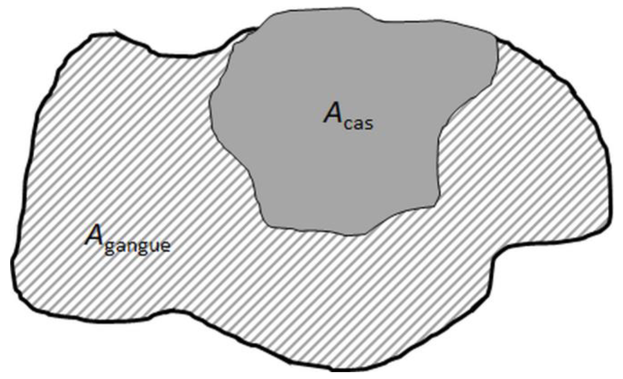
Figure 7 a typical particle image from SEM-based image analysis is shown, which is binarized in cassiterite and the gangue area.
The cassiterite volume liberation is calculated for each particle according to Equation (7):
L cas = A cas A cas + A gangue × 100   in   vol %
where A cas and A gangue denote the proportion of the area of cassiterite and other gangue minerals, respectively. As the data given in the MLA is 2D, the volume liberation for cassiterite is calculated based on obtained area information, considering that the bias for this transformation is in an acceptable range. This is a reasonable assumption given the near isometric shape of most cassiterite grains and the lack of any preferred orientation of mineral grains in the fine-grained skarn ore.
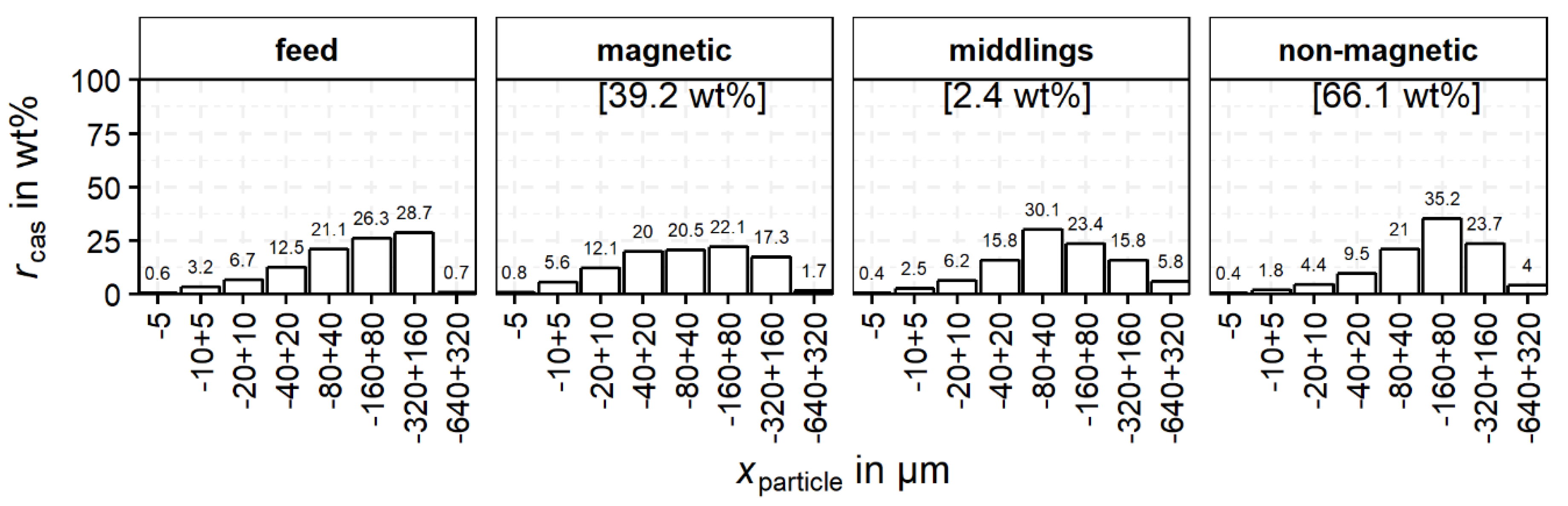
The grouping of the cassiterite-containing particles as a function of particle size is shown in Figure 8. In this diagram, only the particles Ncas (Table 6) are utilized. For the feed and each product p (magnetic, middlings and non-magnetic), rcas,p,i sums up to 100 wt% and i represents the particle size and liberation classes for which rcas is calculated. Therefore, the colors give an indication of the cassiterite distribution within the product with regard to the particle size and cassiterite liberation. For the feed and the three products of magnetic separation, the distribution of cassiterite over the particle size classes is shown in Figure 8.
The distribution of cassiterite in the non-magnetic product shows a clear maximum in the −160 + 80 µm class. However, the maximum for the middlings is in a lower class at −80 + 40 µm. In contrast, the magnetic product shows no clear maximum and a more uniform distribution of the cassiterite between 20–320 µm. The feed material is added for comparison and indicates left skewed distribution with a maximum at −320 + 160 µm.
The distribution of cassiterite in the feed is similar to the cassiterite distribution in the non-magnetic product, also showing a left skewed distribution. The recovery of cassiterite into the middlings and the magnetic product is caused by intergrown iron oxides, especially magnetite which reports completely to these products. Finely, disseminated cassiterite is intergrown with magnetite, which also explains the greater amounts of cassiterite in the finer-grained fractions compared to the non-magnetic and middlings fraction. For a better understanding of this behavior, the liberation of cassiterite in the different size fractions has to be investigated. For this purpose, 
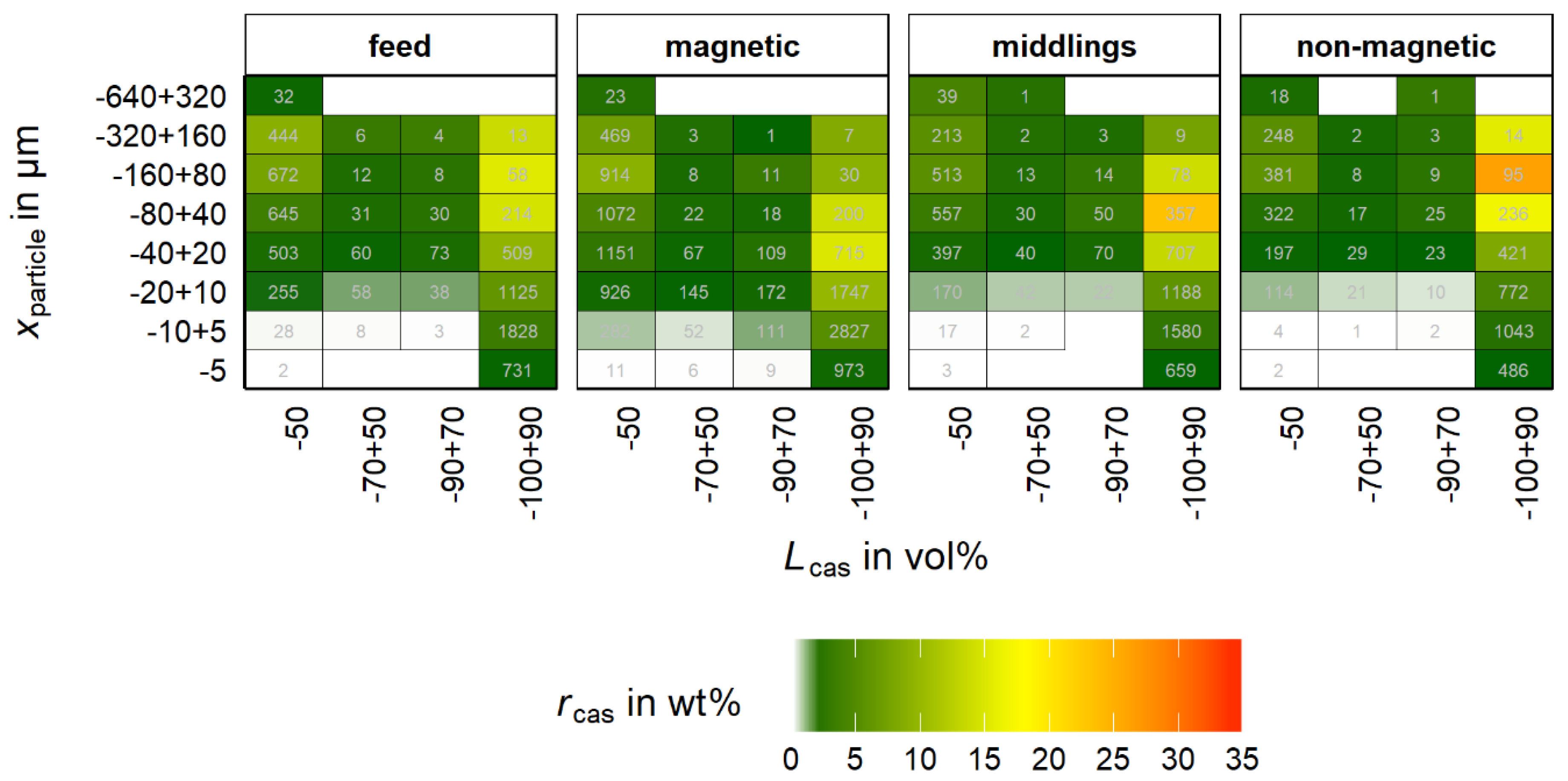
rcas is studied as a function of liberation together with the particle size classes in Figure 9. The rcas for every product sums up to 100% for a better visualization. Further, the color scale displays the cassiterite recovery into the property classes (rcas) for each product individually calculated by Equation (8).
r cas ,   p ,   i = m cas , p , i m cas , p × 100   in   wt %
The number of particles is added for each property class. These values are added for review of the statistical representative status of the data, where a high value of rcas together with a low number of particles is problematic and must be noted.
For all four samples, the cassiterite accumulates in the liberation class −100 + 90%. Further, there is a significant amount of cassiterite in the −50% class. It is worth noting that the depicted class is comprised of a much higher range than the other classes, which influences the optical perception in this diagram. Nevertheless, there is a significant number of particles in all three products with low cassiterite liberation.
Regarding the particle size, the maximum cassiterite recovery is found in the non-magnetic product in the range of −160 + 80 µm, followed by −80 + 40 µm. In comparison, for the magnetic product the maximum cassiterite recovery is in the range of −40 + 20 µm. The maximum is less pronounced than in the non-magnetic product and the cassiterite recovery shows a broader distribution over the −100 + 90% class. Cassiterite with a high degree of liberation predominantly accumulates in the non-magnetic product due to its paramagnetic nature. A discharge into the middlings or magnetic product either must be of statistical nature or caused by additional particle properties beside the content of iron oxides, e.g., mineral association, particle size, shape or density. The influence of these properties cannot be assessed in Figure 9.
Summarizing Figure 9, the cassiterite containing particles are divided into three main liberation groups including low (−50%), intermediate (50%–90%) and high (90%–100%) liberated cassiterite. Another important group represents the fully (100%) liberated cassiterite. This particle section shows no other interconnected mineral in the particle and is therefore of high significance. This group is not visible in Figure 9 as it is included in the −100 + 90% group.
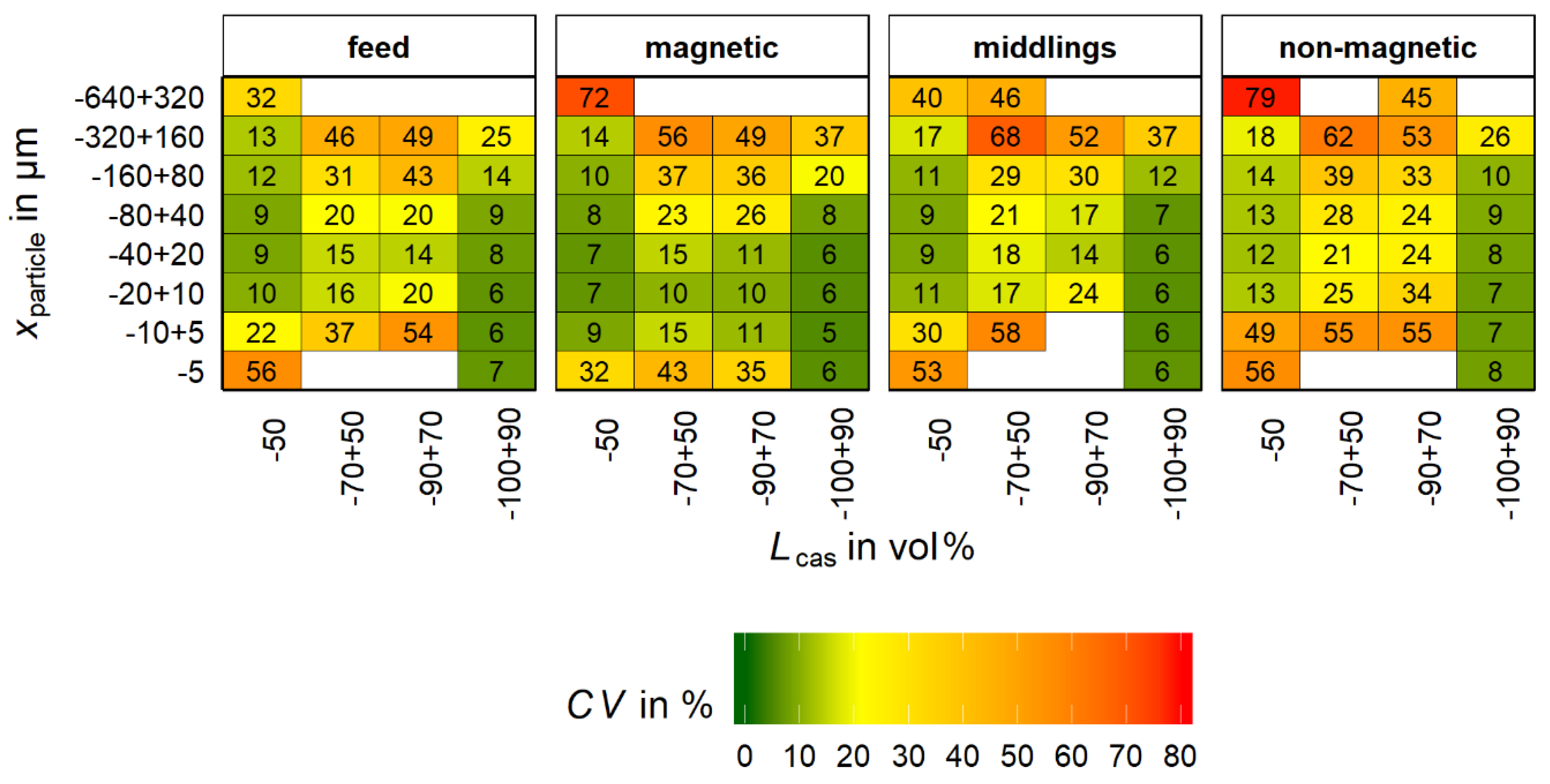
Based on bootstrap resampling (refer to chapter 2.5, N = particle number of MLA sample; M = 1000) the coefficient of variation (CV) was calculated for the bins of Figure 9. The CV for each bin is shown in Figure 10.
From Figure 10 in combination with Figure 9 it is seen that for bins with a low number of particles in the original sample for MLA the value for CV is high. According to Lamberg et al. [22] the maximum acceptable value of CV is in the range of 20%. If the value is higher, bins will be merged. This approach reduces the mean error for the following calculation methods. However, it does not allow a tracking of the bias along the analysis process.
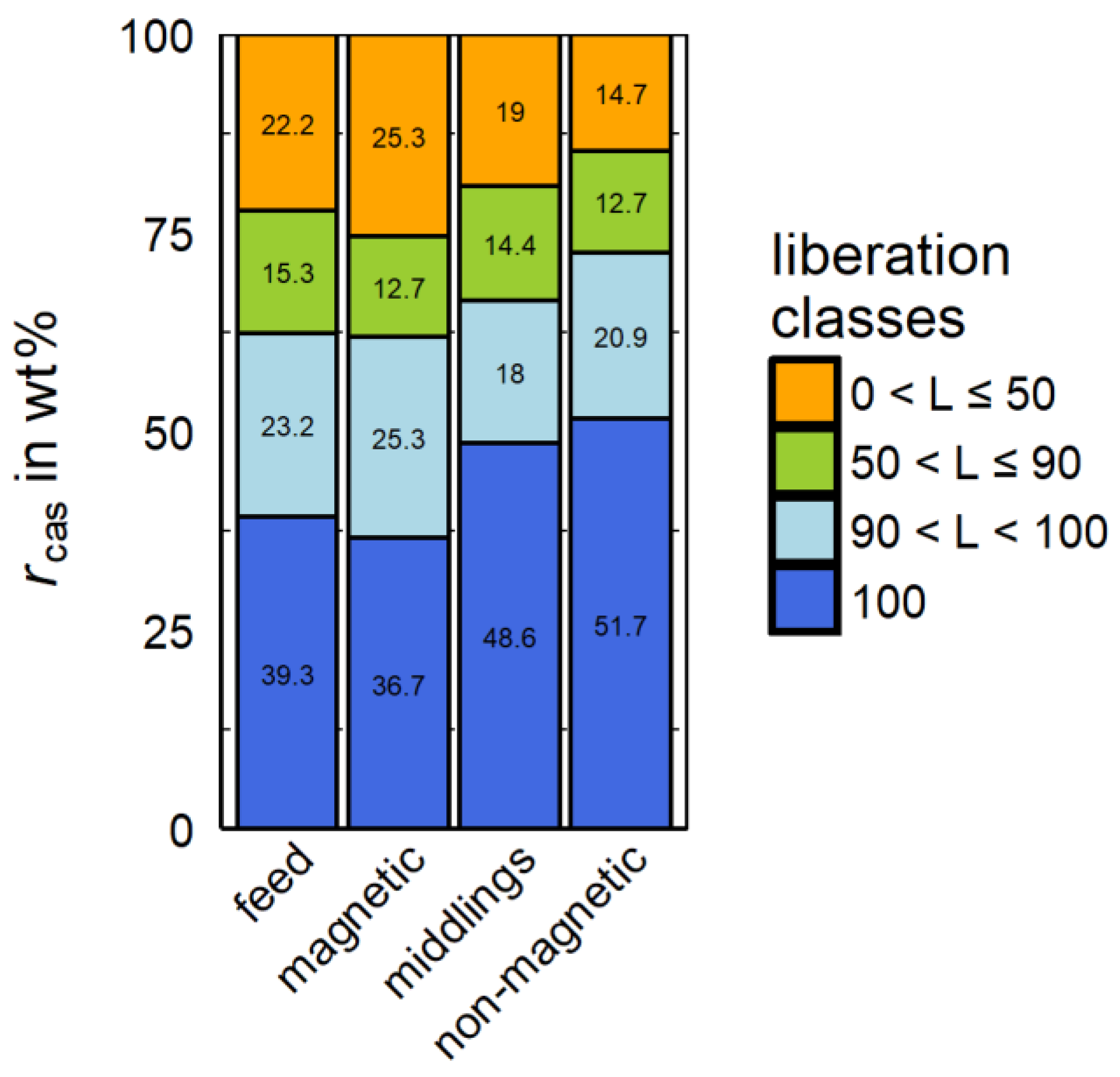
For a better overview of the distribution of cassiterite regarding these described liberation classes, rcas is shown for these groups in Figure 11 for the three products and the feed.
In Figure 11, the 100% liberated cassiterite is the predominant proportion of all products. It should be mentioned that MLA slightly overestimates the liberation degree by only cutting the particles in the cutting plane of the grain mounts and the related 2D character of the data. The described stereological effect leads to the fact that 100% liberated cassiterite can be intergrown with other minerals, which are not visible in MLA as these minerals are not positioned in the cutting plane of the grain mount. Nevertheless, the non-magnetic product shows the highest amount of fully liberated cassiterite compared to all other products and the feed.

3.4.2. Association with Iron Oxides

The association of cassiterite with iron oxides is of high importance. The content of cassiterite together with iron oxides in one particle is relevant for its recovery into the magnetic product. Table 7 shows the particle population that is utilized for the analysis of cassiterite in connection with iron oxides.
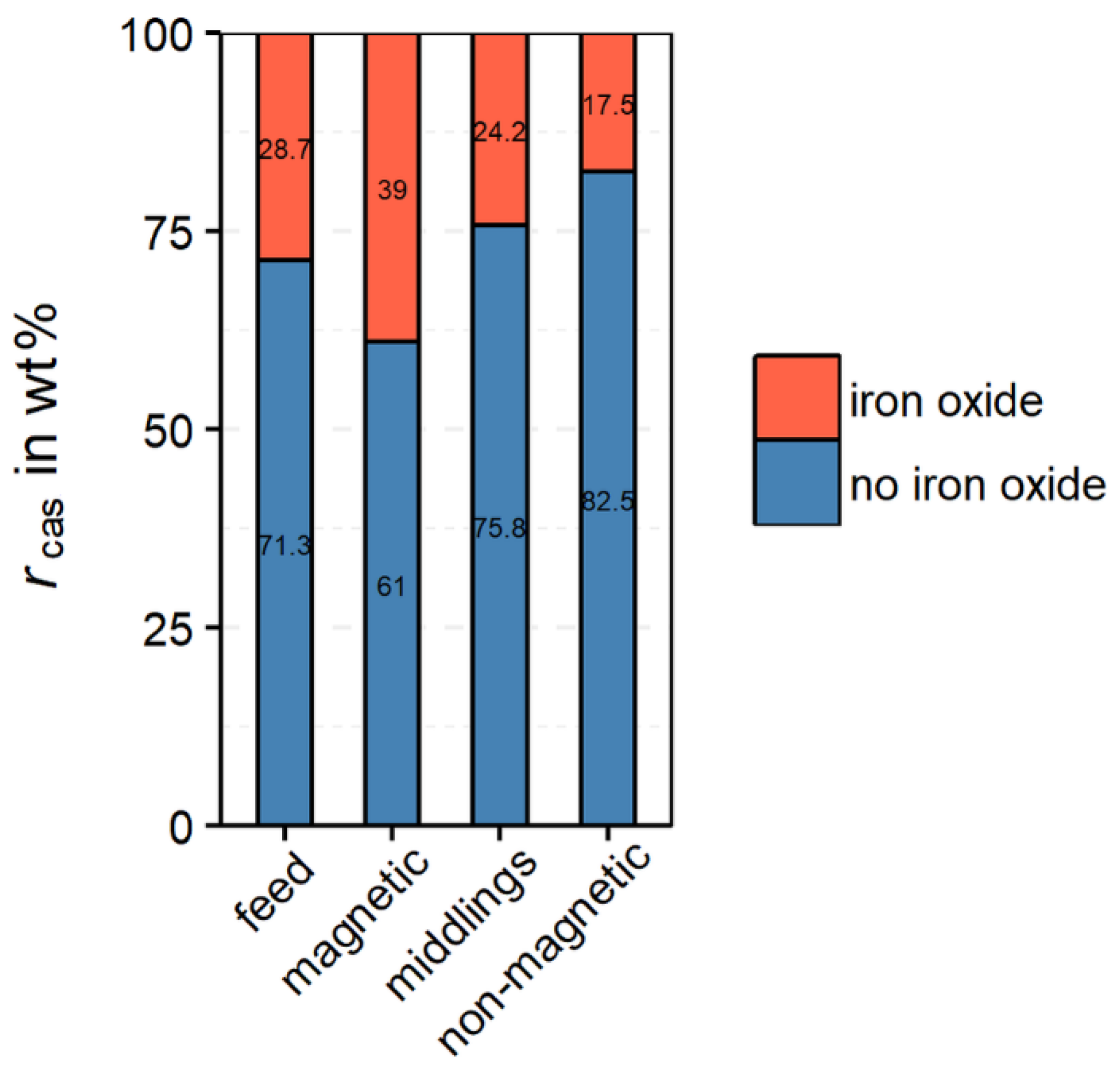
From Figure 12 it follows, that the highest portion of cassiterite intergrown with iron oxides can be found in the magnetic product. Nevertheless, a significant amount of cassiterite (17.5 wt%) is also associated with iron oxides in the non-magnetic product. As no magnetite is present in the non-magnetic product, the cassiterite is only intergrown with hematite. For these particles, a more detailed analysis is necessary.
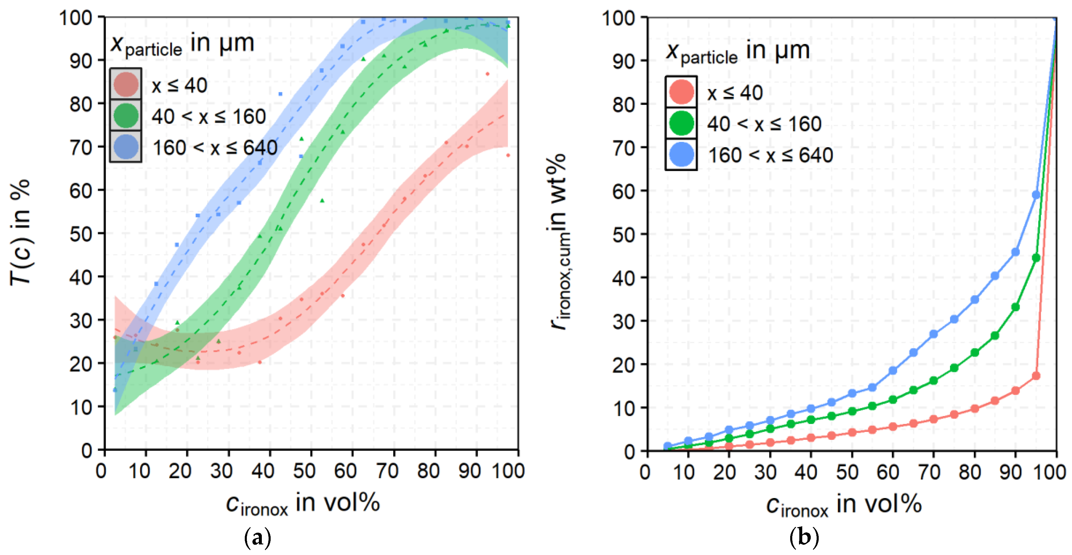
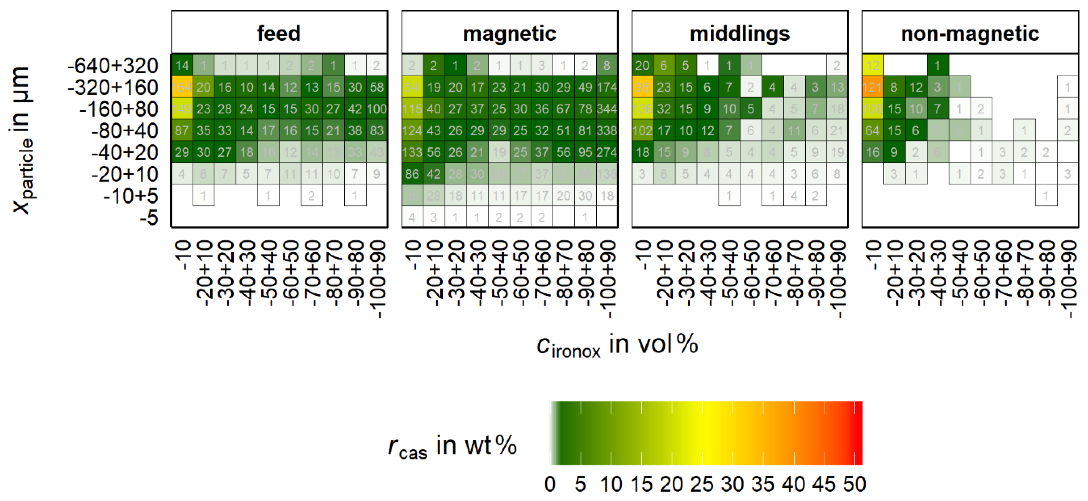
Figure 12 implies the necessity of a more detailed analysis of the particles that are comprised of cassiterite and iron oxides. In Figure 13, the distribution of these particles is shown as a function of particle size and cironox classes.
For rcas, the non-magnetic product shows a clear accumulation at low cironox. The maximum rcas is for cironox at −10 wt % and xparticle at −320 + 160 µm. For the non-magnetic product, the majority of the cassiterite shows cironox below 30 vol%. The magnetic product shows an obviously broader distribution of cassiterite over the cironox classes. Despite that, the maximum is also in the class −10 vol% but significantly less pronounced than in the non-magnetic product. Furthermore, the optical impression in Figure 13 implies a slight shift of rcas to lower particle size classes for the magnetic product compared to the non-magnetic product. The behavior of the middlings shows a clear maximum in the fraction cironox −10 vol% but also a broader distribution of rcas over cironox than in the non-magnetic product. It can be concluded that already small proportions of iron oxides (most probably magnetite) in the particle suffice to recover it in the magnetic product or the middlings.
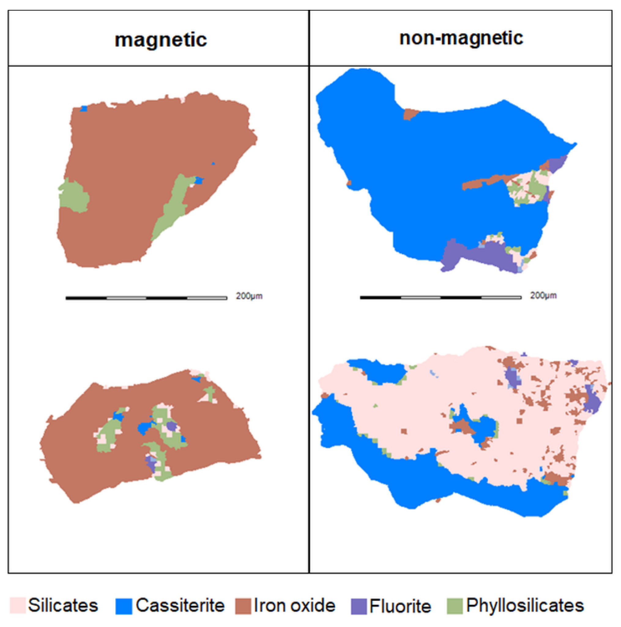
For the magnetic and the non-magnetic products, respectively two typical particle images that contain cassiterite and iron oxides are shown in Figure 14.
As seen in Figure 14, the magnetic product exhibits the finely disseminated cassiterite grains within the matrix of iron oxides. Conversely, in the case of the non-magnetic product, the iron oxides are finely disseminated within matrices of other minerals. These characteristics of the ore material represent one reason for discharge of minerals with iron oxides into the non-magnetic product and the loss of finely intergrown cassiterite into the magnetic product.

3.4.3. Fully Liberated Cassiterite

For an ideal magnetic separation, the assumption is that a particle, solely consisting of cassiterite, can be recovered in the non-magnetic fraction. Table 8 shows, however, that a considerable number of particles that show an apparent (2D) fully liberation of cassiterite are recovered in the magnetic product.
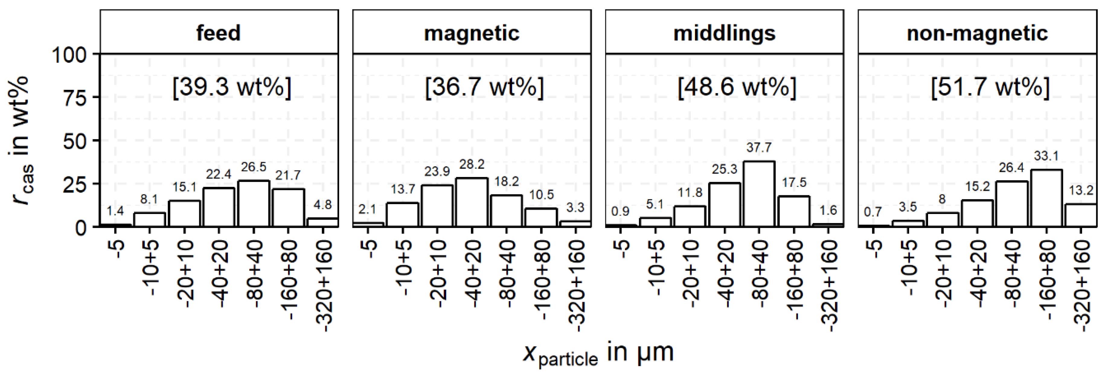
To compare the particle size range of fully-liberated cassiterite, rcas is shown as a function of the particle size classes for the feed and the products of magnetic separation in Figure 15. The distribution for rcas of the magnetic product is shifted to a lower particle size range compared to the non-magnetic product. For the non-magnetic product, the maximum of rcas can be found for the particle size class −160 + 80 µm, whereas for the magnetic product, rcas shows a maximum value in the class −40 + 20 µm.
The described observations lead to the conclusion that one reason for the relatively high recovery of 100% (apparently) liberated cassiterite in the magnetic product is agglomeration of fine particles and their attachment to coarse and high magnetic particles. Nevertheless, as already stated, due to stereological effects the liberation based on MLA data is overestimated. Associated minerals might not be visible in the cutting plane and a proportion of the 100% liberated cassiterite can still be intergrown with some other minerals regarding the three dimensional structure.

4. Conclusions and Outlook

The present study presents the characterization of the magnetic properties and potential magnetic separation in a complex tin-bearing skarn of the Erzgebirge. It is impossible to over-emphasize the application of MLA data coupled with XRD and XRF for the evaluation of such magnetic separation unit operations in mineral processing. Indeed, based on the insights provided by the discussed parameters a relatively simple, efficient work flow for process analysis can be established based on a process mineralogical approach for an ore body which was thought to be uneconomic for many years. It was shown that for an evaluation of the separation efficiency via partition curves, it is also important to take the mass distribution over the volume liberation of iron oxides into account. This helps to explain the high discrepancy of the overall recovery of the iron oxides into the magnetic fraction and the relatively small slope of the partition curve. The main findings of this article can be concluded in the following statements:
  • Besides the iron oxide content, the particle size had a significant influence on the magnetic separation process. The distinction of iron oxides in hematite and magnetite is possible with an additional characterization technique like XRD. All iron oxides in the non-magnetic product were found to be hematite.
  • Partition curves for the evaluation of the separation process were calculated. The overall iron oxide content was used instead of the susceptibility, which is difficult to measure for ferromagnetic materials. The obtained results provided a precise assessment of separation efficiency.
  • The applied magnetic separation was able to reduce the amount of iron oxides to below 5%. However, this caused significant losses of cassiterite into the magnetic product.
  • The main reasons for cassiterite losses into the magnetic product were determined. The most important one is the finely disseminated character of cassiterite in the matrix of iron oxides. Losses of fully liberated cassiterite can be due to agglomeration with iron oxide bearing particles.
  • Losses of cassiterite could be significantly decreased by a further comminution and refeeding of the upper particle size fraction in the magnetic product and by a better dispersion during the separation (e.g., by using a wet magnetic separator).
The study illustrates that the interpretation of MLA data to evaluate the separation efficiency should always contain an assessment of uncertainties. In the presented study, these uncertainties originate from two different sources. First, unbalanced mass streams for single or multiple minerals such as the group of iron oxides reported in the present work. Second, a statistically unrepresentative number of particles in property classes (bins) during particle tracking which were used to track the cassiterite through the process in this case study. In addition to the particle tracking approach by Lamberg et al. [22] the error of the data was monitored and further analyzed in detail. Nevertheless, new approaches urgently need to overcome the problem of discrete bins in particle tracking.

Author Contributions

E.S. and M.B. conceived the paper. M.K. was responsible for sample analysis with a Mineral Liberation Analyzer (MLA) including quality control, data processing and data evaluation. R.T.-D. developed the basis for evaluation of the MLA data in the R statistical environment and interpreted results. R.M. and D.E. were responsible for sample preparation for XRD, data acquisition and evaluation of the measurements using the Rietveld method. E.S., M.B. and J.A. analyzed, interpreted, and joined together all results. T.L., M.R., K.G.v.d.B., as well as U.P., interpreted results, supervised the work and supported preparation of the manuscript.

Funding

This research was funded by BMBF in the r4 program grant number: 033R128.

Acknowledgments

We would like to thank Saxore Bergbau GmbH for providing the material samples and UVR-FIA GmbH for preprocessing of the material.

Conflicts of Interest

The authors declare no conflict of interest.

References

  1. Schuppan, W.; Hiller, A. Die Komplexlagerstätten Tellerhäuser und Hämmerlein, Uranbergbau und Zinnerkundung in der Grube Pöhla der SDAG Wismut; Bergbaumonografie, Landesamt für Umwelt, Landwirtschaft und Geologie, Sächsisches Oberbergamt: Freiberg, Germany, 2012; p. 17. [Google Scholar]
  2. Angadi, S.I.; Sreenivas, T.; Jeon, H.-S.; Baek, S.-H.; Mishra, B.K. A review of cassiterite beneficiation fundamentals and plant practices. Min. Eng. 2015, 70, 178–200. [Google Scholar] [CrossRef]
  3. Xu, C.; Zhang, Y.; Liu, T.; Huang, J. Characterization and Pre-Concentration of Low-Grade Vanadium-Titanium Magnetite Ore. Minerals 2017, 7, 137. [Google Scholar] [CrossRef]
  4. Bulatovic, S.M. Handbook of Flotation Reagents. Chemistry, Theory and Practice, 1st ed.; Elsevier: Amsterdam, The Netherlands, 2010. [Google Scholar]
  5. Falcon, L.M. The gravity recovery of cassiterite. J. S. Afr. Inst. Min. Met. 1982, 4, 112–117. [Google Scholar]
  6. Kern, M.; Möckel, R.; Krause, J.; Teichmann, J.; Gutzmer, J. Calculating the deportment of a fine-grained and compositionally complex Sn skarn with a modified approach for automated mineralogy. Min. Eng. 2018, 116, 213–225. [Google Scholar] [CrossRef]
  7. Little, L.; Becker, M.; Wiese, J.; Mainza, A.N. Auto-SEM particle shape characterisation: Investigating fine grinding of UG2 ore. Min. Eng. 2015, 82, 92–100. [Google Scholar] [CrossRef]
  8. Little, L.; Mainza, A.N.; Becker, M.; Wiese, J.G. Using mineralogical and particle shape analysis to investigate enhanced mineral liberation through phase boundary fracture. Powder Technol. 2016, 301, 794–804. [Google Scholar] [CrossRef]
  9. Leißner, T.; Hoang, D.H.; Rudolph, M.; Heinig, T.; Bachmann, K.; Gutzmer, J.; Schubert, H.; Peuker, U.A. A mineral liberation study of grain boundary fracture based on measurements of the surface exposure after milling. Int. J. Min. Process. 2016, 156, 3–13. [Google Scholar] [CrossRef]
  10. Alsafasfeh, A.; Alagha, L. Recovery of Phosphate Minerals from Plant Tailings Using Direct Froth Flotation. Minerals 2017, 7, 145. [Google Scholar] [CrossRef]
  11. Liu, X.; Zhang, Y.; Liu, T.; Cai, Z.; Sun, K. Characterization and Separation Studies of a Fine Sedimentary Phosphate Ore Slime. Minerals 2017, 7, 94. [Google Scholar] [CrossRef]
  12. Philander, C.; Rozendaal, A. A process mineralogy approach to geometallurgical model refinement for the Namakwa Sands heavy minerals operations, west coast of South Africa. Min. Eng. 2014, 65, 9–16. [Google Scholar] [CrossRef]
  13. Evans, C.L.; Napier-Munn, T.J. Estimating error in measurements of mineral grain size distribution. Min. Eng. 2013, 52, 198–203. [Google Scholar] [CrossRef]
  14. Lotter, N.O.; Evans, C.L.; Engstrőm, K. Sampling—A key tool in modern process mineralogy. Min. Eng. 2018, 116, 196–202. [Google Scholar] [CrossRef]
  15. Leißner, T.; Bachmann, K.; Gutzmer, J.; Peuker, U.A. MLA-based partition curves for magnetic separation. Min. Eng. 2016, 94, 94–103. [Google Scholar] [CrossRef]
  16. Jeong, S.; Kim, K. Pre-Concentration of Iron-Rich Sphalerite by Magnetic Separation. Minerals 2018, 8, 272. [Google Scholar] [CrossRef]
  17. Chehreh Chelgani, S.; Leißner, T.; Rudolph, M.; Peuker, U.A. Study of the relationship between zinnwaldite chemical composition and magnetic susceptibility. Min. Eng. 2015, 72, 27–30. [Google Scholar] [CrossRef]
  18. Waters, K.E.; Rowson, N.A.; Greenwood, R.W.; Williams, A.J. Characterising the effect of microwave radiation on the magnetic properties of pyrite. Sep. Purif. Technol. 2007, 56, 9–17. [Google Scholar] [CrossRef]
  19. Tripathy, S.K.; Singh, V.; Rama Murthy, Y.; Banerjee, P.K.; Suresh, N. Influence of process parameters of dry high intensity magnetic separators on separation of hematite. Int. J. Min. Process. 2017, 160, 16–31. [Google Scholar] [CrossRef]
  20. Fandrich, R.; Gu, Y.; Burrows, D.; Moeller, K. Modern SEM-based mineral liberation analysis. Int. J. Min. Process. 2007, 84, 310–320. [Google Scholar] [CrossRef]
  21. Gottlieb, P.; Wilkie, G.; Sutherland, D.; Ho-Tun, E.; Suthers, S.; Perera, K.; Jenkins, B.; Spencer, S.; Butcher, A.; Rayner, J. Using quantitative electron microscopy for process mineralogy applications. JOM 2000, 52, 24–25. [Google Scholar] [CrossRef]
  22. dLamberg, P.; Vianna, S. A Technique for Tracking Multiphase Mineral Particles in Flotation Circuits; XXII ENTMME/VII MSHMT: Ouro Preto, MG, Brazil, 2007. [Google Scholar]
  23. Ueda, T.; Oki, T.; Koyanaka, S. Statistical effect of sampling particle number on mineral liberation assessment. Min. Eng. 2016, 98, 204–212. [Google Scholar] [CrossRef]
  24. Heinig, T.; Bachmann, K.; Tolosana-Delgado, R.; van den Boogaart, G.; Gutzmer, J. Monitoring Gravitational and Particle Shape Settling Effects on MLA Sampling Preparation; International Association for Mathematical Geosciences: Freiburg, Germany, 2015. [Google Scholar]
  25. Figueroa, G.; Moeller, K.; Buhot, M.; Gloy, G.; Haberla, D. Advanced Discrimination of Hematite and Magnetite by Automated Mineralogy. In Proceedings of the 10th International Congress for Applied Mineralogy (ICAM), Trondheim, Norway, 1–5 August 2012; pp. 197–204. [Google Scholar]
  26. Rosenblum, S.; Brownfield, I.K. Magnetic Susceptibility of Minerals; U.S. Department of Interior, U.S. Geological Survey: Washington, DC, USA, 1999; p. 10.
  27. dMadai, E. Limitations of magnetic separation in relation to particle size and susceptibility. Aufbereit. Tech. Min. Process. 1998, 39, 394–406. [Google Scholar]
  28. Doebelin, N.; Kleeberg, R. Profex: A graphical user interface for the Rietveld refinement program BGMN. J. Appl. Crystallogr. 2015, 48, 1573–1580. [Google Scholar] [CrossRef] [PubMed]
  29. ALS Geochemistry. Shedule of Services and Fees: Refractory Ores and Geological Materials; ALS Ltd.: Brisbane, Australia, 2017. [Google Scholar]
  30. Gu, Y. Automated Scanning Electron Microscope Based Mineral Liberation Analysis an Introduction to JKMRC/FEI Mineral Liberation Analyzer. J. Min. Mater. Charact. Eng. 2003, 2, 33–41. [Google Scholar]
  31. Efron, B.; Tibshirani, R. An Introduction to the Bootstrap; Chapman & Hall: Boca Raton, FL, USA, 1998. [Google Scholar]
  32. Mariano, R.A.; Evans, C.L. Error analysis in ore particle composition distribution measurements. Min. Eng. 2015, 82, 36–44. [Google Scholar] [CrossRef]
  33. Leißner, T. Beitrag zur Kennzeichnung von Aufschluss- und Trennerfolg am Beispiel der Magnetscheidung. Ph.D. Thesis, Freiberg University of Mining and Technology, Freiberg, Germany, 2015. [Google Scholar]
  34. Jacoby, W.G. Loess: A nonparametric, graphical tool for depicting relationships between variables. Elect. Stud. 2000, 19, 577–613. [Google Scholar] [CrossRef]
  35. Hunt, C.P.; Moskowitz, B.M.; Banerjee, S.K. Magnetic properties of rocks and minerals: A Handbook of Physical. AGU Reference Shelf 3. Rock Phys. Phase Relat. 1995, 3, 189–204. [Google Scholar]
  36. Grant, D.C.; Goudie, D.J.; Voisey, C.; Shaffer, M.; Sylvester, P. Discriminating hematite and magnetite via Scanning Electron Microscope–Mineral Liberation Analyzer in the −200 mesh size fraction of iron ores. Appl. Earth Sci. 2018, 127, 30–37. [Google Scholar] [CrossRef]
  37. Parian, M.; Lamberg, P.; Rosenkranz, J. Developing a particle-based process model for unit operations of mineral processing—WLIMS. Int. J. Min. Process. 2016, 154, 53–65. [Google Scholar] [CrossRef]
Figure 1. Particle size distribution (from laser diffraction measurements) and grain size distribution of cassiterite (from Mineral Liberation Analyzer—MLA data) of the feed material for magnetic separation.
Minerals 08 00390 g001
Figure 2. Rotating drum type magnetic separator (1 feeder; 2 drum; 3 permanent magnet and 4 splitter).
Minerals 08 00390 g002
Figure 3. Comparison of mass fractions in different particle size classes for the real feed (real) and recalculated feed (recalc.). The latter is recalculated from the MLA-data of the three products of magnetic separation.
Minerals 08 00390 g003
Figure 4. Comparison of mineral contents of real feed and recalculated feed based on the three products from magnetic separation (a) for all mineral groups; (b) without iron oxides closed to 100 wt%) (N = particle number of MLA sample; M = 1000). The median marks the mid-point of the data and is shown by the line that divides the box into two parts. Half the values are larger than or equal to this value and half are less. The middle “box” represents the middle 50% of values for the group. The range of scores from lower to upper quartile is referred to as the inter-quartile range. The middle 50% of values fall within the inter-quartile range. Outliers that fall out of the boxplot range are marked by dots.
Minerals 08 00390 g004
Figure 5. (a) T(c) vs. mineral content in the particles for cassiterite (red) and iron oxides (blue); (b) cumulative distribution of iron oxides (rironox,cum) in the content classes (cironox) of the feed material.
Minerals 08 00390 g005
Figure 6. T(c) vs. cironox (a) for three different particle size classes; (b) cumulative distribution of iron oxides (rironox,cum) in the content classes (cironox) of the feed material for three different particle size classes.
Minerals 08 00390 g006
Figure 7. Typical 2D projection of a particle in the cutting plane from MLA measurement.
Minerals 08 00390 g007
Figure 8. Distribution of cassiterite (rcas) in different size classes for feed and the products (values in brackets indicate distribution of cassiterite into the products from Table 5).
Minerals 08 00390 g008
Figure 9. Distribution of cassiterite (rcas) as a function of xparticle classes and Lcas classes (recovery in each product sums up to 100%; green: 1%, yellow: 17.5%, red: 35%). The numbers in the boxes indicate the amount of particles in each bin.
Minerals 08 00390 g009
Figure 10. Coefficient of variation (CV) for the bins of xparticle classes and Lcas based on data from bootstrap resampling; green: 0%, yellow: 20%, red: 80%). The numbers in the boxes indicate the value of CV for each bin.
Minerals 08 00390 g010
Figure 11. Distribution of cassiterite (rcas) in the different liberation classes for the three products.
Minerals 08 00390 g011
Figure 12. Distribution of cassiterite (rcas) in particles with iron oxides and without iron oxides.
Minerals 08 00390 g012
Figure 13. Distribution of cassiterite (rcas) as function of xparticle and cironox in the feed and the products (recovery in each product sums up to 100%; green: 1%, yellow: 25%, red: 50%). The numbers in the boxes indicate the amount of particles in each bin.
Minerals 08 00390 g013
Figure 14. Examples of particle images for particles containing cassiterite and iron oxides in the magnetic and the non-magnetic products.
Minerals 08 00390 g014
Figure 15. Distribution of cassiterite (rcas) in 100% liberated class as function of xparticle size for the different products (values in brackets indicate proportion of 100% liberated cassiterite of total cassiterite in feed and each product).
Minerals 08 00390 g015
Table 1. Modal mineralogy defined by the Mineral Liberation Analyzer (MLA) of the input material.
Mineral GroupsContent in wt%
Silicates47
Phyllosilicates16
Iron oxides29
Fluorite2
Sulfides2
Cassiterite4
Table 2. Susceptibility ranges for some chosen minerals [26].
MineralSusceptibility in 10−9 m3kg−1
Magnetite>6505
Hematite720–6505
Cassiterite<22.5
Table 3. X-ray fluorescence (XRF) analysis of cSn and cFe measured for real feed and the recalculated feed based on the three products from magnetic separation.
XRFMLA
Real FeedRecalc. FeedReal FeedRecalc. Feed
cSn3.443.213.423.64
cFe29.7528.6927.8731.74
All values in wt%.
Table 4. cironox, magnetite and hematite proportions for the real feed, recalculated feed and the products measured by X-ray diffractometry (XRD). All values for cironox in wt%, for magnetite and hematite in rel.%.
Real FeedMagneticMiddlingNon-MagneticRecalc. Feed
cironox32.553.116.74.833.2
Magnetite485156not detected48
Hematite52494410052
Table 5. Mass recovery, contents and mineral recovery with correlated error (standard deviation) estimated by bootstrap resampling and error propagation of the different products and feed.
MagneticMiddlingsNon-MagneticFeed
Rm56.6 ± 2.11.7 ± 0.241 ± 2.1-
ccas2.5 ± 0.15.4 ± 0.36.2 ± 0.43.8 ± 0.2
cironox60.2 ± 0.412.6 ± 0.53.8 ± 0.230.4 ± 0.5
Rcas39.2 ± 3.22.42 ± 0.566.1 ± 7.8-
Rironox112.1 ± 4.80.7 ± 0.15.2 ± 0.5-
All values in wt%—concentrations determined with MLA.
Table 6. Number of particles (Ntotal: all particles; NCas: particles containing cassiterite).
FeedMagneticMiddlingsNon-Magnetic
Ntotal193,476299,510143,41191,558
Ncas739112,08167774505
Table 7. Number of particles in the feed and three products classifying, Ncas, ironox, particles containing cassiterite and iron oxides and Ncas, no ironox as particles includes cassiterite and no iron oxides.
FeedMagneticMiddlingsNon-Magnetic
Ncas, ironox15083561797447
Ncas, no ironox5883852059804057
Table 8. Number of particles (Ncas: particles containing cassiterite; Ncas,100%: particles with 100% volume liberated cassiterite).
FeedMagneticMiddlingsNon-Magnetic
Ncas739112,08167774505
Ncas,100%4362595344372990

