1. Introduction
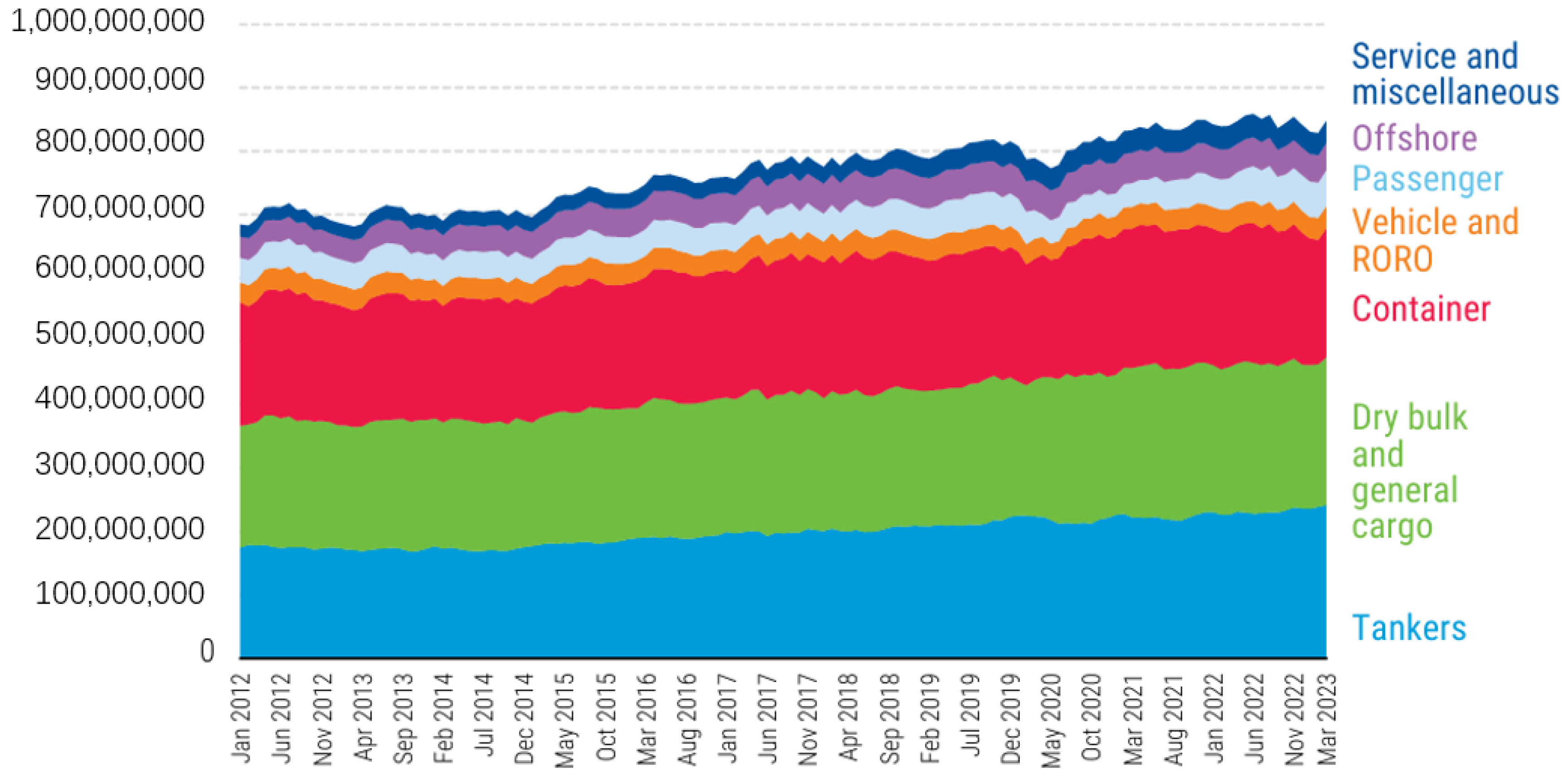
According to the United Nations’ Review of Maritime Transport published in 2023, the maritime transport sector accounts for over 80% of global trade volume and contributes approximately 3% of worldwide greenhouse gas emissions. As illustrated in
Figure 1, the sector’s greenhouse gas emissions exhibited a notable increase of approximately 20% over the decade from 2012 to 2023. This upward trend underscores the growing environmental impact of maritime logistics despite ongoing efforts to enhance operational efficiency within the industry.
At the 70th session of the International Maritime Organization’s (IMO) Marine Environment Protection Committee (MEPC) held in October 2016, a regulatory measure was adopted to reduce the permissible sulfur content in ship fuel oil from 3.5% to 0.5%, effective 1 January 2020. Furthermore, the revised IMO Greenhouse Gas (GHG) Reduction Strategy adopted in July 2023 established ambitious targets: a 20% improvement in the energy efficiency of international shipping by 2030, relative to 2008 levels, and a 70% reduction in maritime GHG emissions by 2040 compared to 2008 [
2]. These mandates underscore the urgency for the maritime sector to rapidly decarbonize. Hydrogen has emerged as a leading candidate for achieving these goals, offering zero greenhouse gas emissions, energy conversion efficiencies nearing 80% in fuel cell applications, and advantages such as operational flexibility, zero local pollution, and diverse production pathways [
3,
4,
5].
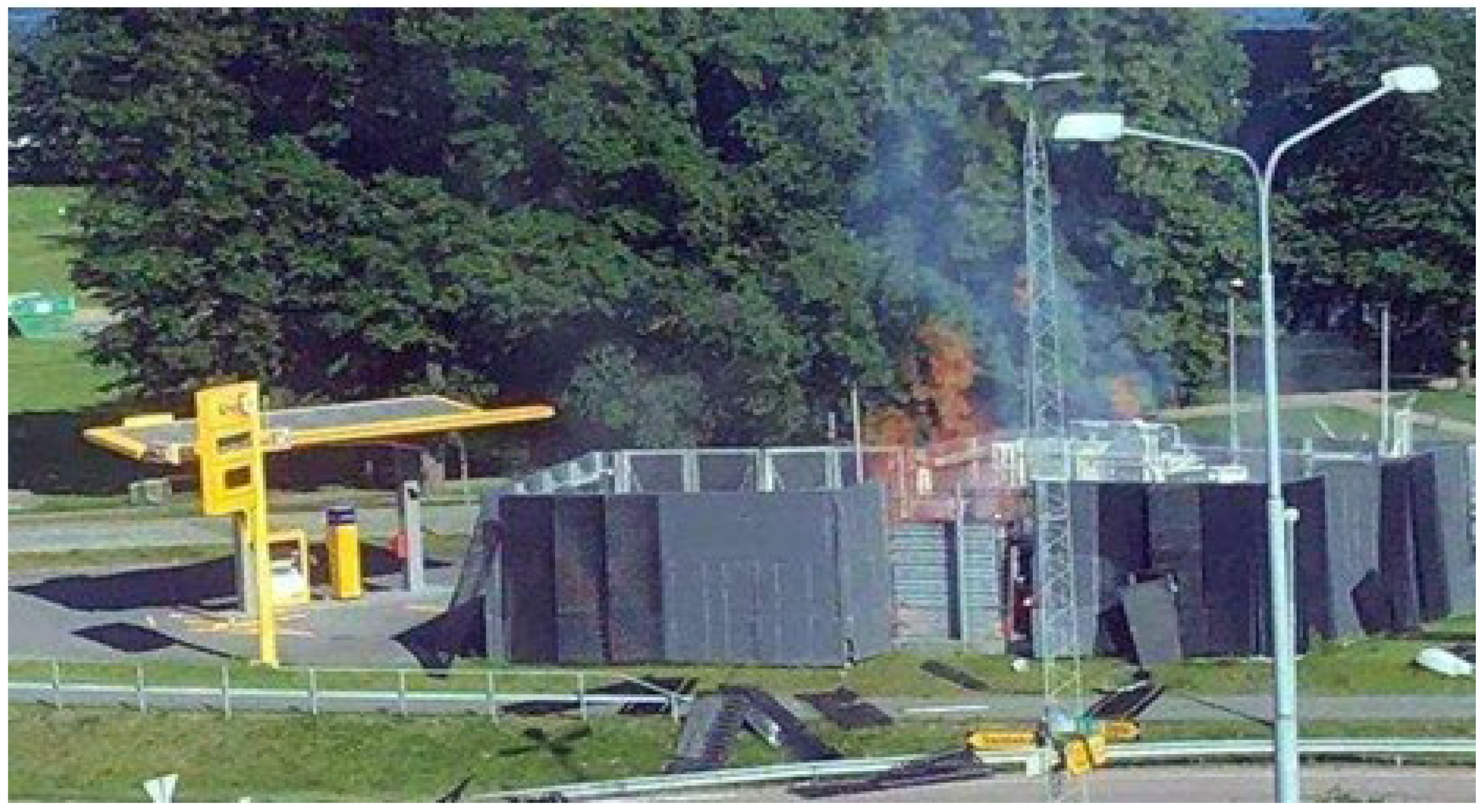
Hydrogen’s high energy density—approximately three times that of gasoline—and its wide flammability range (4–75% concentration in air) pose significant safety risks. A stark example is the June 2019 explosion at a hydrogen refueling station in Sandvika, Oslo, Norway (
Figure 2). The incident injured two individuals and disrupted regional hydrogen infrastructure. Investigations by safety consultancy Gexcon traced the cause to hydrogen leakage from an improperly assembled plug screw, with ignition triggered by friction from gravel on the station’s ground surface [
6].
Another case, illustrated in
Figure 3, involves a 2021 tube trailer accident. A tire fire caused overheating of the hydrogen storage vessel, prompting the safety valve to activate and release hydrogen over 30 min. This resulted in flames reaching 10–20 m in height. However, rapid emergency containment measures prevented catastrophic escalation [
7].
Marine hydrogen storage systems must ensure operational safety under prolonged maritime conditions, including vessel vibrations, unpredictable oceanic environments, and internal pressure fluctuations caused by liquid hydrogen evaporation and sloshing. Robust design standards are essential to withstand these dynamic stresses. Additionally, fatigue life analysis is critical to predict the structural integrity of storage tanks under cyclic loading and to evaluate their long-term durability in harsh maritime settings. Such studies are vital to address the compounded effects of mechanical wear, environmental corrosion, and pressure variations inherent to hydrogen storage at sea.
Hydrogen has been utilized across various industries for decades; however, its expanding application in fuel cells has recently heightened safety concerns [
8]. To ensure its safe deployment, two critical dimensions must be addressed. First, proactive risk mitigation through accident prevention is essential. This includes rigorous protocols such as regular pressure testing and precision inspections of storage tanks to identify latent defects or vulnerabilities. Second, minimizing the consequences of potential accidents is equally vital. For instance, material brittleness under cryogenic conditions and unanticipated environmental shifts—factors often overlooked in initial design phases—can introduce unforeseen risks of failure or leakage [
9]. Significant research and development efforts have been dedicated to enhancing the safety of hydrogen storage tanks, leading to advancements in material selection, thermal stress management, and structural integrity under static pressure. Studies on collision simulations for vehicle-mounted tanks at varying speeds have also provided critical insights for improving marine storage tank design. Han et al. [
10] conducted a finite element analysis of a Type III 70 MPa hydrogen storage tank for vehicles, focusing on failure mechanisms under low-speed collisions. Using a layered modeling approach, they evaluated the tank’s performance under internal pressure (70 MPa) and impact loading. By applying the Hashin failure criterion, they confirmed the tank’s post-collision safety and investigated failure modes across collision speeds, ultimately validating the tank’s potential for reuse after low-impact events. Jang Dae-jun et al. [
11] emphasized that liquid hydrogen (LH
2; After that, they are all abbreviated as LH
2) storage tanks must withstand loads from insulation systems (1 atm), vapor pressure, and hydrostatic pressure. For marine applications, they highlighted the necessity of accounting for dynamic loads and thermally induced stresses from temperature gradients. Kwak Hyo-Seo [
12] performed a thermo-structural coupling analysis of an LH
2 tank, identifying stress concentration vulnerabilities in the dome section compared to the cylindrical body. Ogata [
13] observed that 304 L stainless steel exposed to 10 bar gaseous hydrogen exhibited reduced elongation and cross-sectional area at various temperatures, though the effects were less severe than those under high-pressure hydrogen. Consequently, 316 L stainless steel was selected as the material for the liquid hydrogen storage tank in this study. While sloshing research for marine tanks has predominantly focused on ambient-temperature fluids or cryogenic liquefied natural gas (LNG), studies on liquid hydrogen (LH
2) sloshing remain limited. However, insights from aerospace and automotive sectors offer valuable references. Lacapere [
14] conducted sloshing experiments using cryogenic liquid nitrogen and oxygen, concluding that pressure drops in sealed containers arise primarily from interfacial heat and mass transfer during sloshing. Moran et al. [
15] investigated LH
2 sloshing in a 62 ft
3 (1750 L) spherical tank for the National Aero-Space Plane (NASP) project, adjusting parameters such as sloshing frequency, amplitude, pressurization type, ramp pressure, and vapor space volume. Their findings revealed that sloshing near the tank’s resonant frequency could induce severe vapor space collapse, necessitating caution in design. Berglund et al. [
16] numerically analyzed LH
2 sloshing in a two-stage aircraft tank during coast phases, demonstrating that excessive sloshing could destabilize propulsion systems. Sherif et al. [
17] highlighted that fluid sloshing in automotive LH
2 tanks converts kinetic energy into thermal energy, accelerating hydrogen evaporation rates. Although extensive studies have explored hydrodynamic behavior and thermal interactions (e.g., pressure drops and heat exchange between subcooled liquid and warm vapor) in LH
2 sloshing, limited attention has been paid to structural defects or fatigue damage caused by sloshing under wave-induced external loads in marine environments. This gap underscores the need for further research to address the unique challenges of hydrogen storage in maritime applications.
Maritime vessels operating on long-distance voyages face inherent risks: safety incidents at sea can escalate into complex rescue scenarios, jeopardizing both crew lives and cargo. Consequently, ensuring the structural integrity of onboard hydrogen storage tanks is a critical priority in advancing hydrogen-powered shipping. Ships are continuously subjected to dynamic external loads, such as wave-induced forces, which induce hull vibrations. These vibrations inevitably propagate to internal hydrogen storage tanks, compromising their durability and potentially leading to premature failure—a risk that could result in tanks failing to meet their designed operational lifespan.
This study aims to address these challenges by conducting a fluid–structure interaction (FSI) analysis of a marine-grade liquid hydrogen (LH2) storage tank. The focus is on evaluating the effects of wave-induced sloshing dynamics on the tank’s structural behavior during navigation and predicting its fatigue life under cyclic loading. By integrating hydrodynamic and structural simulations, the research seeks to establish safety benchmarks and inform design optimizations to enhance the reliability of hydrogen storage systems in maritime environments.
Structurally, marine liquid hydrogen tanks are predominantly cylindrical vessels with rotational symmetry—a design chosen for uniform stress distribution under ideal conditions. However, this inherent symmetry is compromised during navigation due to asymmetric wave-induced sloshing loads. The resulting asymmetric fluid–structure interactions generate localized stress concentrations that accelerate fatigue failure, creating a fundamental conflict between geometric symmetry and operational asymmetry. This study addresses this symmetry-asymmetry dichotomy through sensitivity-driven design optimization. Although the existing research on liquefied natural gas and aerospace LH2 storage tanks provides a valuable foundation, the operating conditions for Marine LH2 storage are significantly different. Compared with LNG, the vapor of liquid hydrogen is extremely light, diffuses very quickly, has a wider explosive limit range (4–75%), and has a very low ignition energy. After leakage, it is more likely to be accidentally ignited, posing a greater safety challenge. Due to the influence of waves, Marine liquid hydrogen storage tanks are constantly subjected to shaking loads. Most of the liquid hydrogen storage tanks used in aerospace are for single use or short-term repeated use (such as in space shuttles). The design life is very short (from a few minutes to several days). However, ships are required to have a service life of up to 20 to 30 years, during which they have to endure the corrosion of the Marine environment, repeated loading and unloading cycles, and long-term temperature fatigue. Maintainability and detectability are key design considerations.
3. Fluid–Structure Interaction Analysis and Fatigue Analysis of Hydrogen Storage Tanks
In this study, fluid–structure interaction (FSI) analysis was employed because the pressure changes caused by the sloshing of liquid hydrogen directly affect the storage tank. First, the sloshing behavior of liquid hydrogen was analyzed through fluid dynamics analysis, and the time-dependent pressure changes inside the tank were derived. ANSYS, used for the analysis, utilizes the finite volume method for fluid dynamics analysis, so a computational fluid dynamics (CFD) model of the internal tank requiring fluid behavior analysis was modeled and analyzed.
Additionally, to analyze the effects of fluid sloshing within the tank on the structure, the time-dependent pressure changes results derived from the fluid analysis were utilized in the dynamic response analysis required for structural strength analysis. Unlike fluid analysis, structural analysis employs the finite element method (FEM). Therefore, finite element analysis models were developed for the tank, platform, supports, and other components requiring strength analysis, with physical data from the fluid domain connected to the structural boundaries to perform the analysis.
3.1. Computational Fluid Dynamics (CFD) Model and Boundary Conditions and Loading Conditions
The computational fluid dynamics (CFD) model of the internal tank for examining the pressure distribution caused by liquid sloshing in the internal tank is shown in
Figure 12. It consists of 459,781 nodes, 166,812 cells, and 765,876 faces.
For safety reasons, liquid hydrogen storage tanks are operated with an initial filling level of 60% rather than 100%. As shown in
Figure 13, the boundary conditions for the fluid analysis of the internal storage tank were set as fixed walls with no heat transfer to the external environment. Specifically, the lower 60% region was defined as the liquid phase, and the remaining 40% region was designated as the gas phase. The internal temperature of the tank was set to −253 °C.
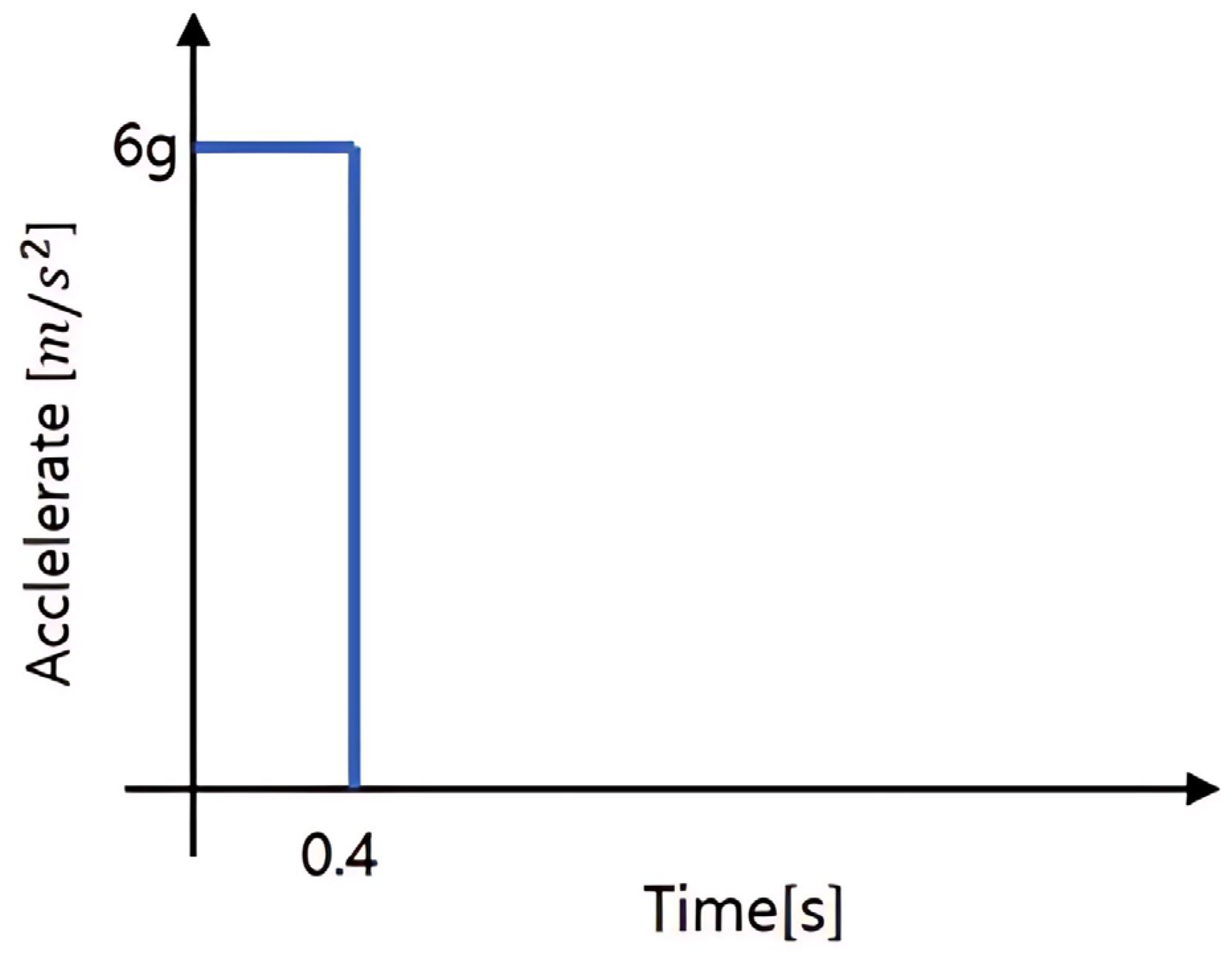
Additionally, the loading condition as shown in
Figure 14 was applied in the Z-axis direction (see
Figure 13) at the center of mass of the tank. A 6 g acceleration was imposed for a duration of 400 ms and then removed, enabling an investigation of pressure changes as liquid hydrogen sloshes due to inertial effects.
3.2. Fluid Analysis Results
As shown in
Figure 15 Due to the excitation (acceleration), after liquid hydrogen collides with the right wall, it does not immediately rebound but overturns toward the top of the tank. When the acceleration is removed after 400 ms, part of the liquid hydrogen flows along the left wall and collides with the liquid hydrogen at the bottom. Thereafter, due to inertia, the liquid hydrogen sloshes freely, causing strong mixing between the gas and liquid phases. At 1.0 s, under the influence of gravitational acceleration, the liquid hydrogen gradually separates from the gas and returns to the tank bottom. During the falling process, bubbles are clearly observed to form within the liquid hydrogen. After 2.0 s, the liquid hydrogen gradually settles to the tank bottom and continues oscillatory motion due to inertia, but the amplitude of sloshing decreases as the kinetic energy of the liquid hydrogen diminishes, eventually returning to a stable state. At this point, a reduction in internal bubbles is also confirmed.
The fluid analysis results indicate that when the tank undergoes significant excitation, liquid hydrogen sloshes with large amplitude, and in severe cases, it can lead to a situation where the entire tank bottom is occupied by gas for a certain period. Additionally, during the process of liquid hydrogen returning to the bottom, it may entrain a large amount of gas, resulting in numerous bubbles within the liquid hydrogen. These bubbles can negatively affect the operation of liquid hydrogen pumps and may lead to risks due to incomplete fuel supply during ship navigation.
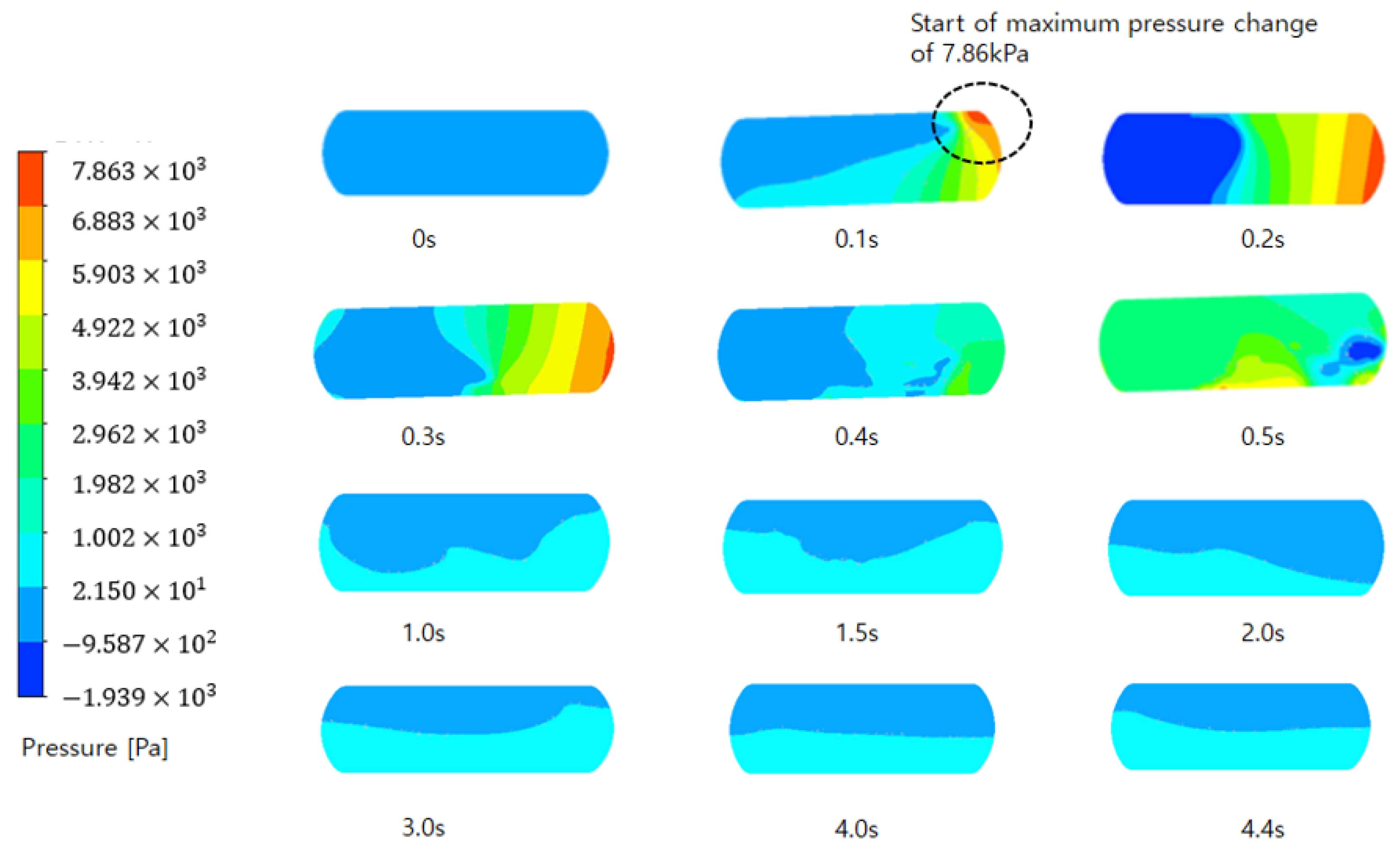
Figure 16 illustrates the pressure changes within the tank caused by liquid sloshing during the sloshing process. Initially, the pressure remains stable at the design working pressure of 3 MPa without any variation. From 0.1 s onward, as liquid hydrogen begins to slosh and collides with the right dome, the maximum pressure is observed to increase by 7.86 kPa. This maximum pressure increase is localized to a small region at the upper right corner.
At 0.2 s, the pressure changes gradually propagate to the entire dome of the tank. Meanwhile, partial pressure reduction occurs due to vapor condensation caused by gas–liquid mixing. By 0.3 s, most of the gas is surrounded by liquid, leading to a general pressure increase throughout the tank. However, the primary pressure increase remains concentrated in the right dome area subjected to acceleration excitation. Although the pressure magnitude does not decrease from the 7.86 kPa increase, the spatial extent of the high-pressure region is observed to shrink compared to 0.2 s. From 0.4 s onward, as the acceleration is removed, the sloshing-induced pressure gradually decreases but does not fully return to a stable state, fluctuating between 21.4 Pa and 1.002 kPa. Additionally, while the distribution of pressure-increased regions continues to change with the movement of liquid hydrogen, the pressure values themselves exhibit no significant variations.
The formation of high-stress and high-pressure concentrations is a direct consequence of the interaction between the sloshing fluid dynamics and the specific geometric features of the tank. As illustrated in
Figure 15 and
Figure 16, the initial high-impact pressure peak (7.86 kPa increase) occurs locally at the upper right dome due to the impulsive load generated when liquid hydrogen, driven by acceleration, collides with the high-curvature geometry of the dome. This geometric configuration causes a rapid change in fluid momentum, concentrating stress in this region. Subsequently, the pressure wave propagates across the dome surface, and the general pressure rise throughout the tank is exacerbated by the confinement of vapor space as it becomes surrounded by liquid. Following the removal of acceleration, the continued sloshing generates dynamic fluctuating pressures on the tank walls, particularly during the drain-back process where gas-entrained liquid impacts broader areas like the left wall and bottom. These sustained hydrodynamic loads, combined with the structural response at geometric discontinuities (e.g., the dome-cylinder junction), are the primary physical mechanisms leading to the observed stress concentrations. This analysis underscores that both the local impulsive loads on high-curvature surfaces and the global dynamic pressures from large-scale sloshing are critical for structural design considerations.
3.3. Structural Interaction Analysis Using Fluid Analysis Results
3.3.1. Finite Element Analysis Model, Boundary Conditions, and Loading Conditions
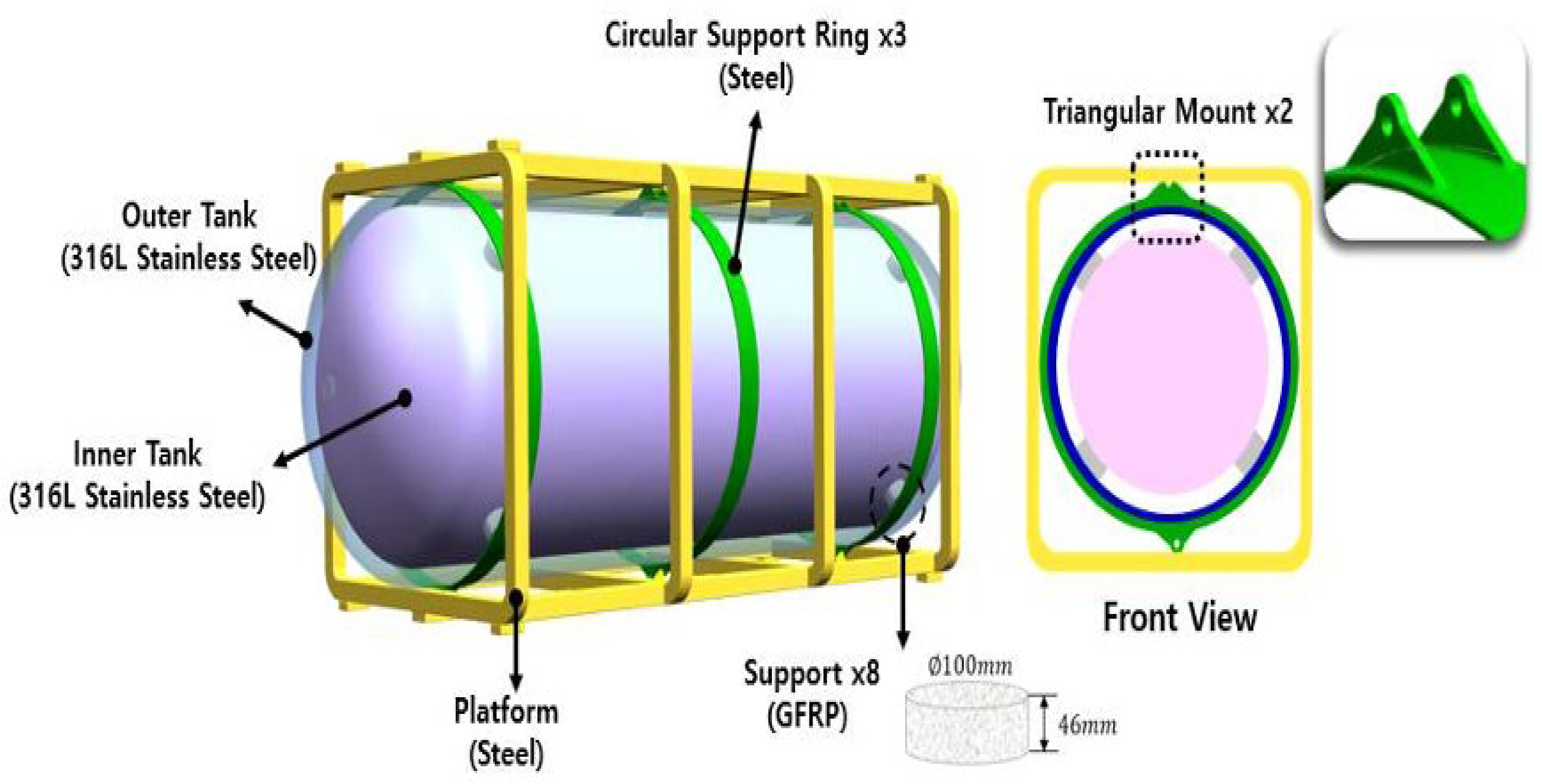
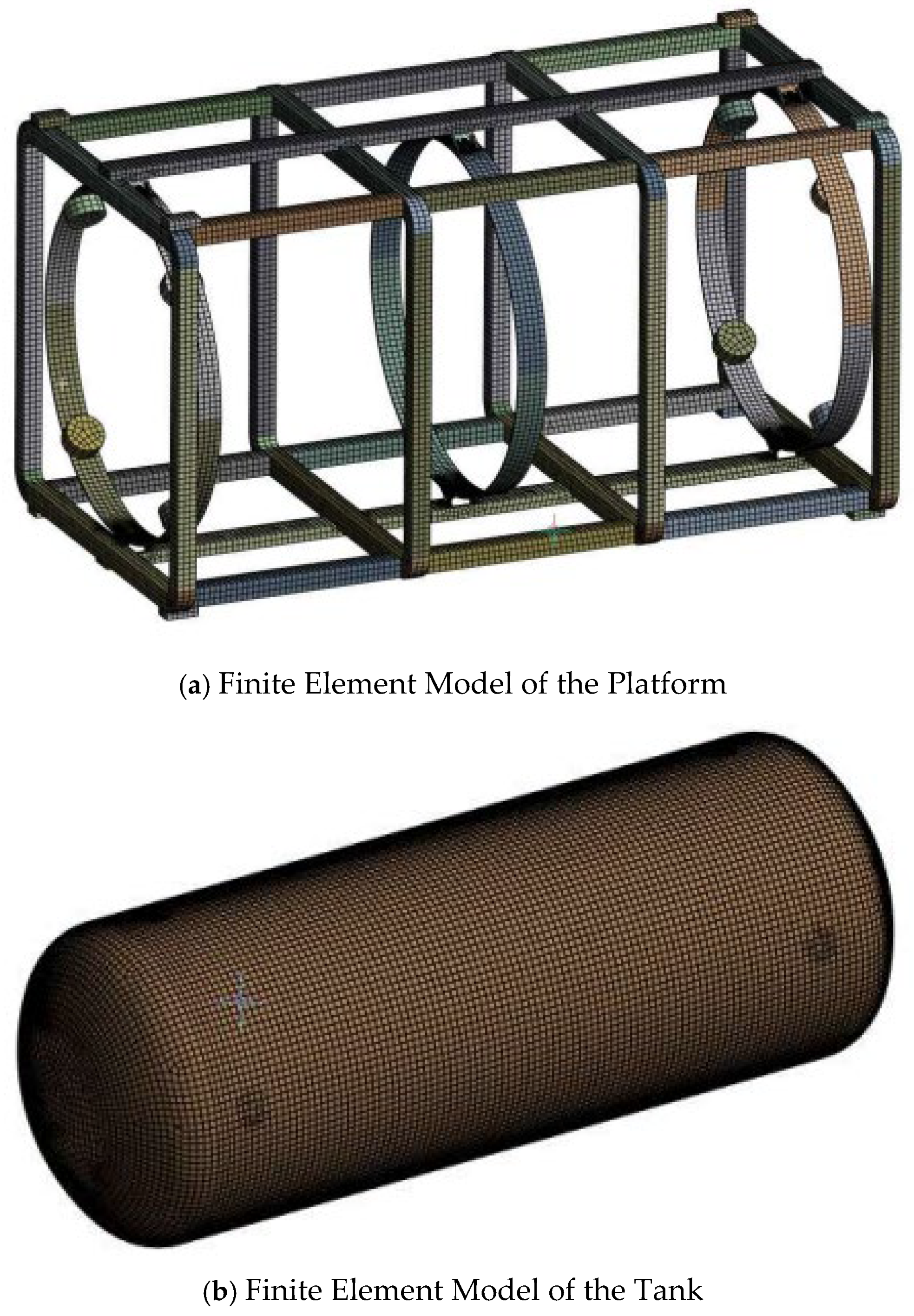
The finite element model of the hydrogen storage tank used for finite element analysis is shown in
Figure 17. To apply the pressure changes in the internal tank derived from fluid analysis as boundary conditions (pressure loads) in the structural analysis of the internal tank, the mesh quality of the boundary surface (in this study, the internal tank) is critical. The Matched Mesh option provided by ANSYS was used to ensure that the nodes of the internal tank (the boundary surface) directly coincide with those from the fluid analysis results. The elements used were ‘Shell 181’ and ‘Solid 185’ provided by ANSYS, with a total of 67,562 nodes and 65,765 elements used for modeling.
To apply the time-dependent pressure distribution caused by liquid sloshing to structural analysis, time-series pressure change data for the entire internal tank from fluid analysis were extracted, and boundary conditions were applied in the direction of the right dome across the entire surface of the internal tank, as shown in
Figure 18. Since the internal pressure reaches its maximum value at 0.3 s, structural displacements and stresses are expected to be highest around 0.3 s. Gravitational acceleration was applied to account for the effect of self-weight, and finite element analysis was performed by fixing the bottom portion where the platform is anchored to the ship. The masses of the hydrogen storage tank and platform are 768.51 kg and 153.72 kg, respectively.
3.3.2. Displacement and Stress Analysis Results
Figure 19 shows the displacement analysis results of the structure obtained through fluid–structure interaction (FSI) analysis. The maximum displacement occurred at 0.4 s, calculated as 0.766 mm in the internal storage tank of
Figure 19. This maximum displacement occurred in the right dome section of the tank, which is the direction in which the liquid is sloshing.
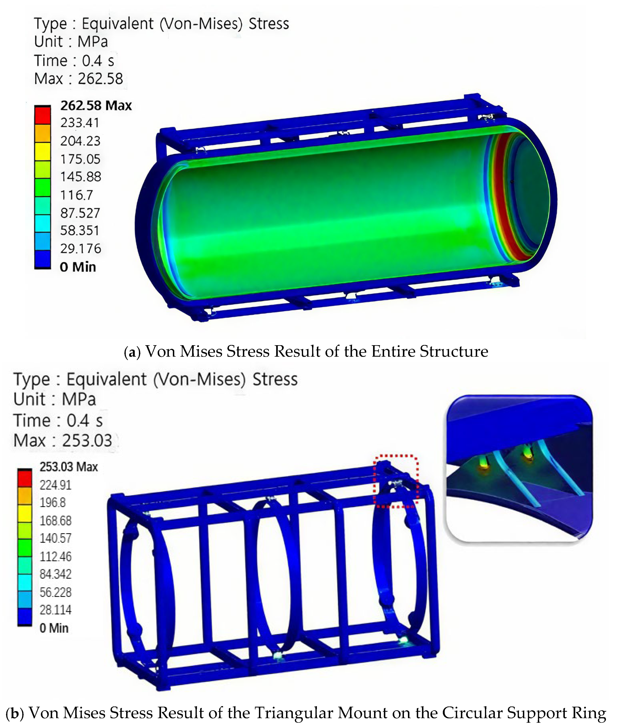
The stress results of the fluid–structure interaction (FSI) analysis are shown in
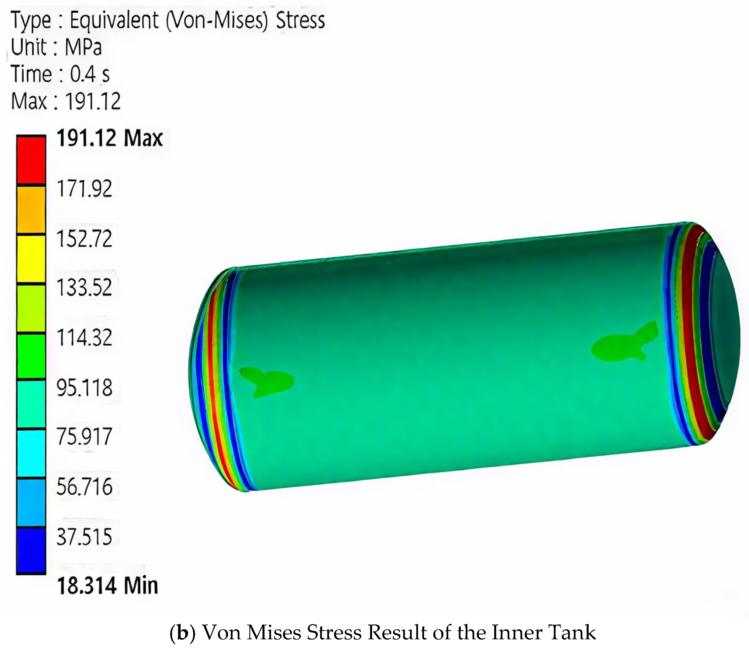
Figure 18. High stress distribution is observed in the direction of liquid hydrogen sloshing within the internal storage tank, with the maximum stress calculated as 262.58 MPa at 0.4 s in the dome section of the internal storage tank in
Figure 20a. Since the allowable stress of the internal storage tank’s material, 316 L Stainless Steel, is only 200 Mpa, this may have a significant impact on operational safety.
Additionally, as shown in
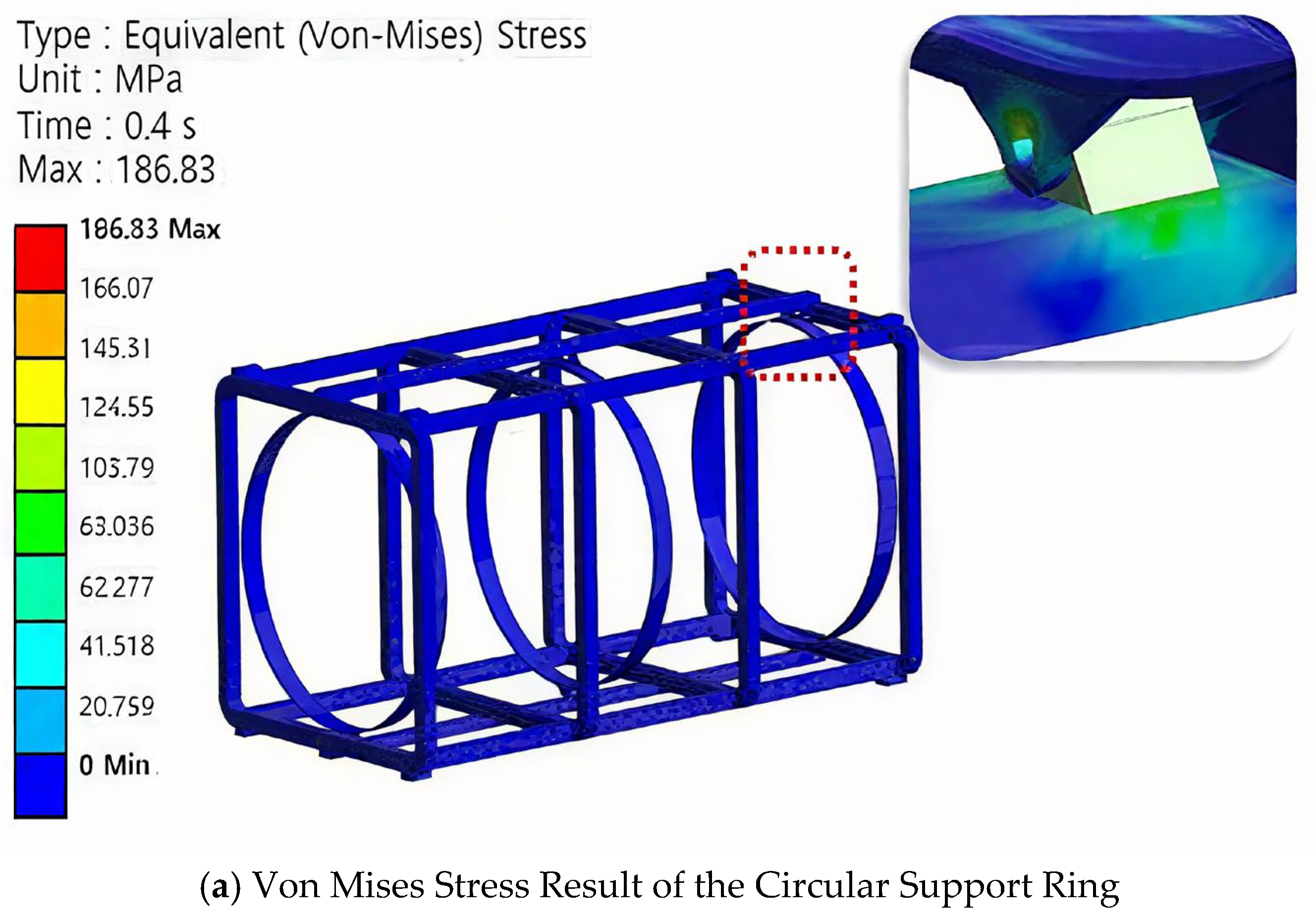
Figure 20b, high stress of 253.03 Mpa occurred in the triangular amounts of the circular fixing devices used for tank connection on the platform.
Sloshing of the liquid within a liquid hydrogen storage tank can induce stress concentration in specific areas, particularly in regions with weaker structural strength. If repeated pressure increases occur inside the tank due to liquid hydrogen vibrations, fatigue will accumulate. Although 316 L Stainless Steel exhibits excellent durability, repeated stress fluctuations can impact the fatigue life of the structure. Hydrogen storage tanks for marine applications must maintain stability amid hull vibrations and irregular operational environments. If continuous pressure changes and stresses arise in the storage tank due to wave loads and ship movements, fatigue damage to the tank may occur. Therefore, it is critical to ensure the tank’s durability through fatigue life assessment.
Maximum stress (262.58 MPa) occurred at the right dome—precisely where sloshing impacts broke structural symmetry. Crucially, the triangular mounts (
Figure 20b) exhibited 253.03 MPa stress despite symmetric arrangement, revealing that geometric discontinuities amplify asymmetric loading effects. This demonstrates how local symmetry-breaking features dominate failure initiation under asymmetric operational conditions.
3.4. Fatigue Analysis of Hydrogen Storage Tank
3.4.1. Fatigue Analysis Condition
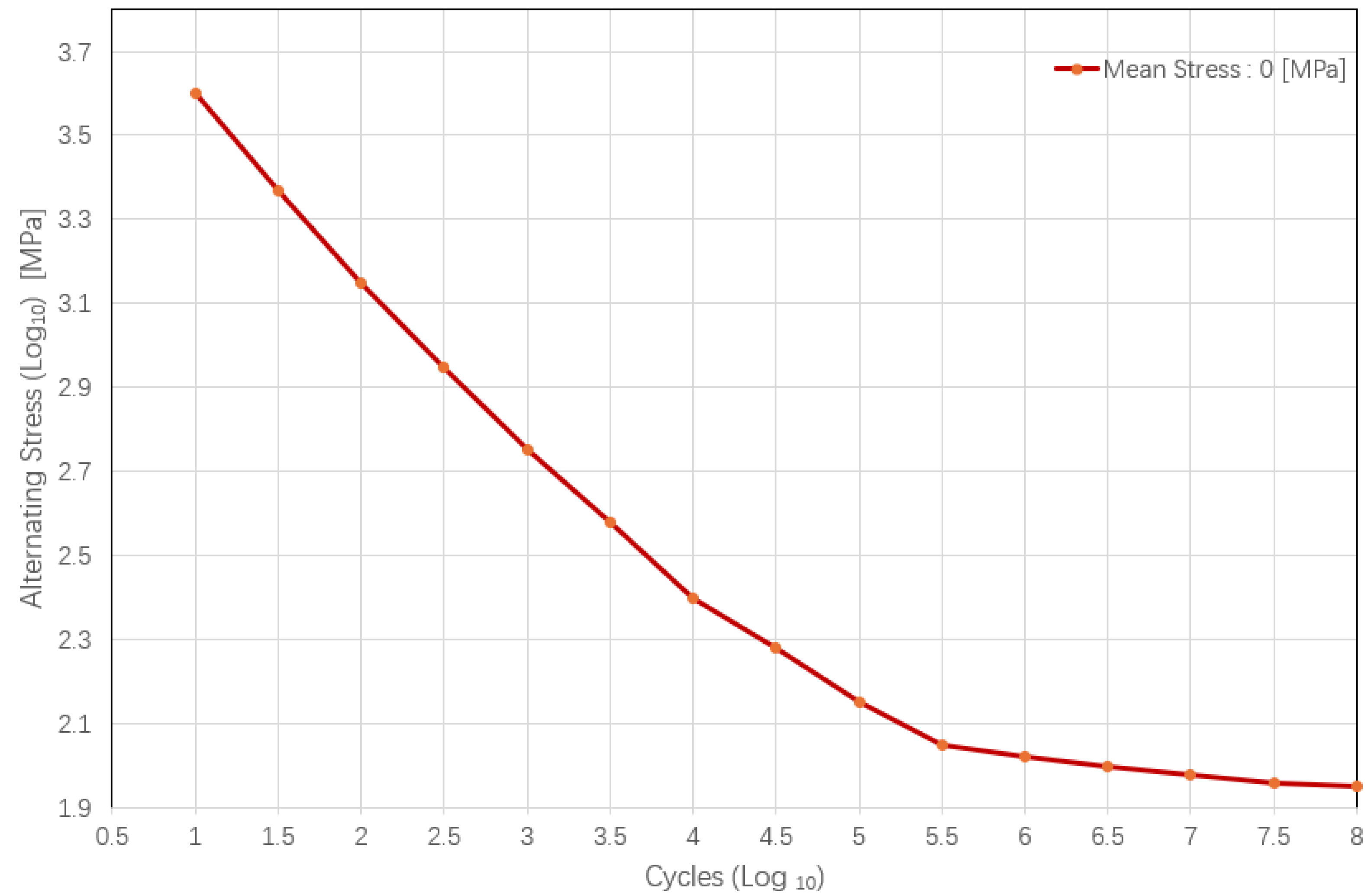
According to the “Rules for Natural Gas as Fuel for Ships” of the China Classification Society (CCS), the fatigue life must be at least 10
6 cycles when subjected to wave loads [
33]. The stress variation from when liquid hydrogen experiences acceleration due to wave loads until the sloshing phenomenon ceases was defined as 1 cycle, and the fatigue life under repeated application of this stress history was predicted.
To calculate fatigue life, the stress history was first modified to Zero Mean Stress using the Goodman mean stress equation (Equation (2)). Subsequently, the fatigue life was calculated using Miner’s cumulative damage rule (Equation (3)) and the material’s fatigue life diagram.
: Alternating Stress Amplitude
: Mean Stress
: Endurance Limit
: Ultimate Tensile Strength
D: Cumulative Damage (Failure Occurs when )
: Number of Cycles applied at Stress Level
: Number of Cycles to Failure at Stress Level
: Total Number of Stress Level
3.4.2. Fatigue Analysis Results
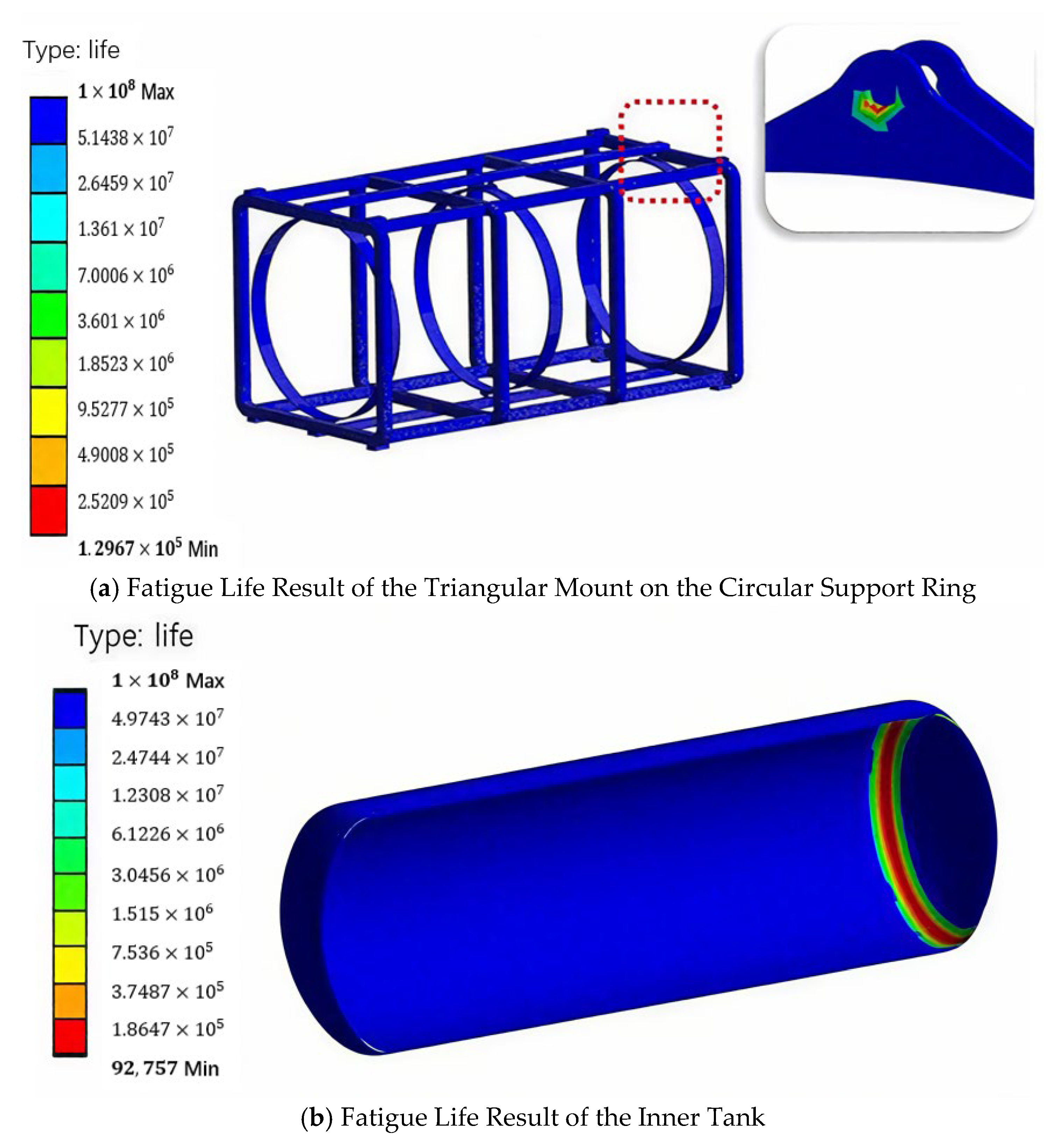
The fatigue analysis results of the storage tank structure caused by liquid sloshing inside the hydrogen storage tank in this study are shown in
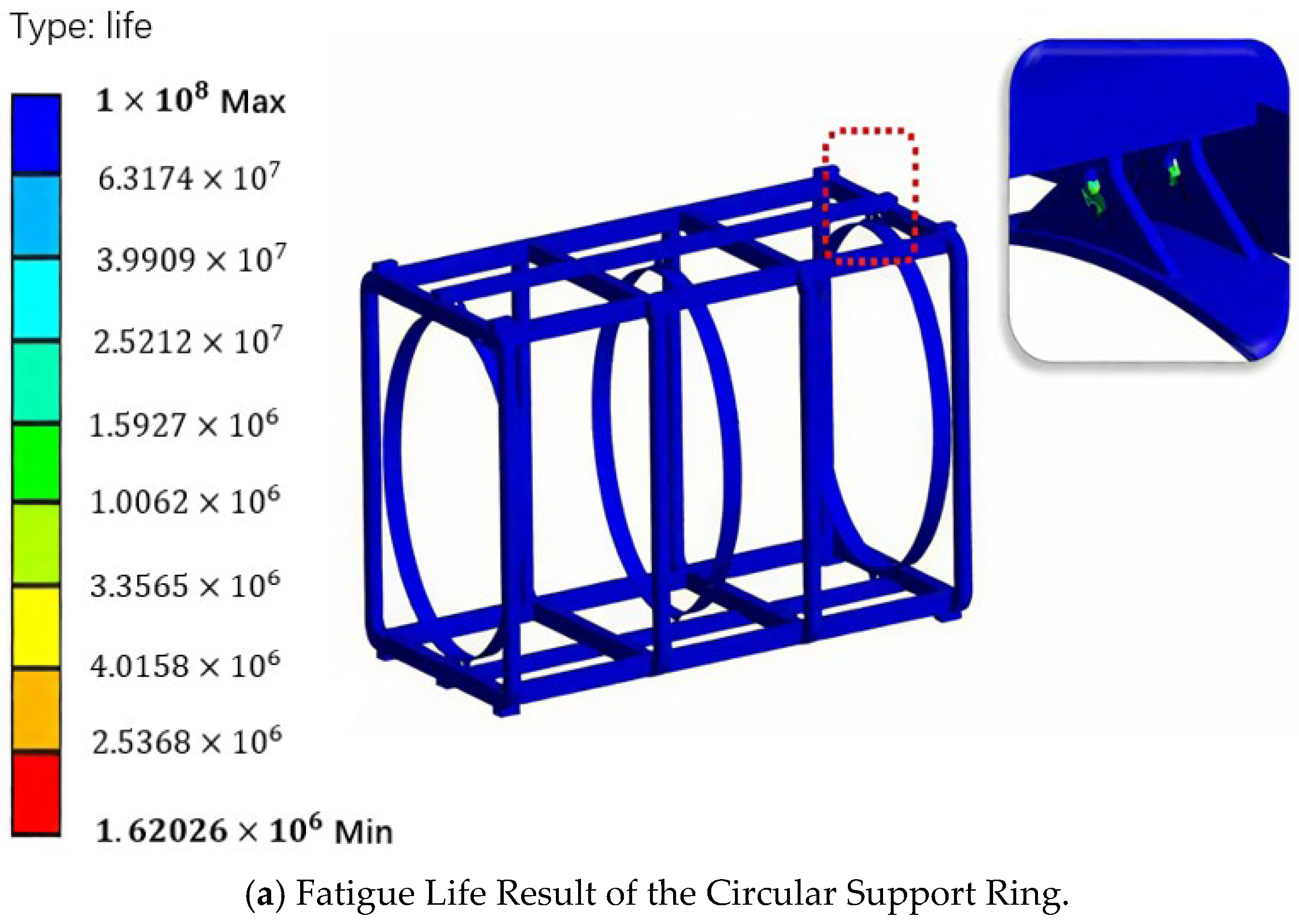
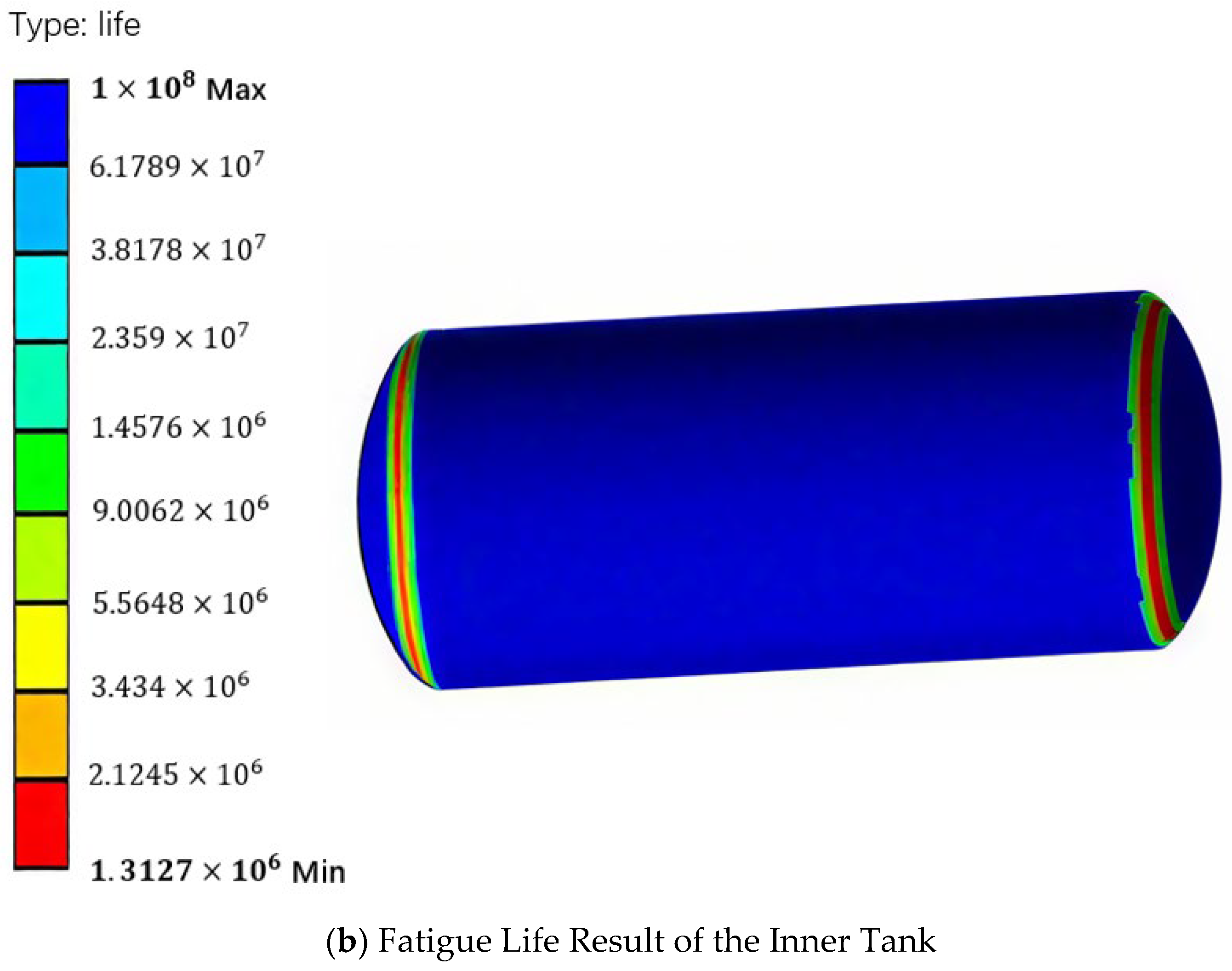
Table 5. For the external tank, the fatigue life results indicated a minimum life of 10
8 cycles, which was calculated as infinite life. However, in the triangular mounts of the circular fixing device connecting the platform and the tank in
Figure 21a, the fatigue life was 129,670 cycles, failing to meet the target life of 10
6 cycles. Additionally, the internal storage tank in
Figure 21b showed the lowest fatigue life of 92,757 cycles, predicting that it would be the first to fail when subjected to cumulative repeated stresses.
Therefore, since the triangular mounts of the circular fixing device in
Figure 21a and the internal tank in
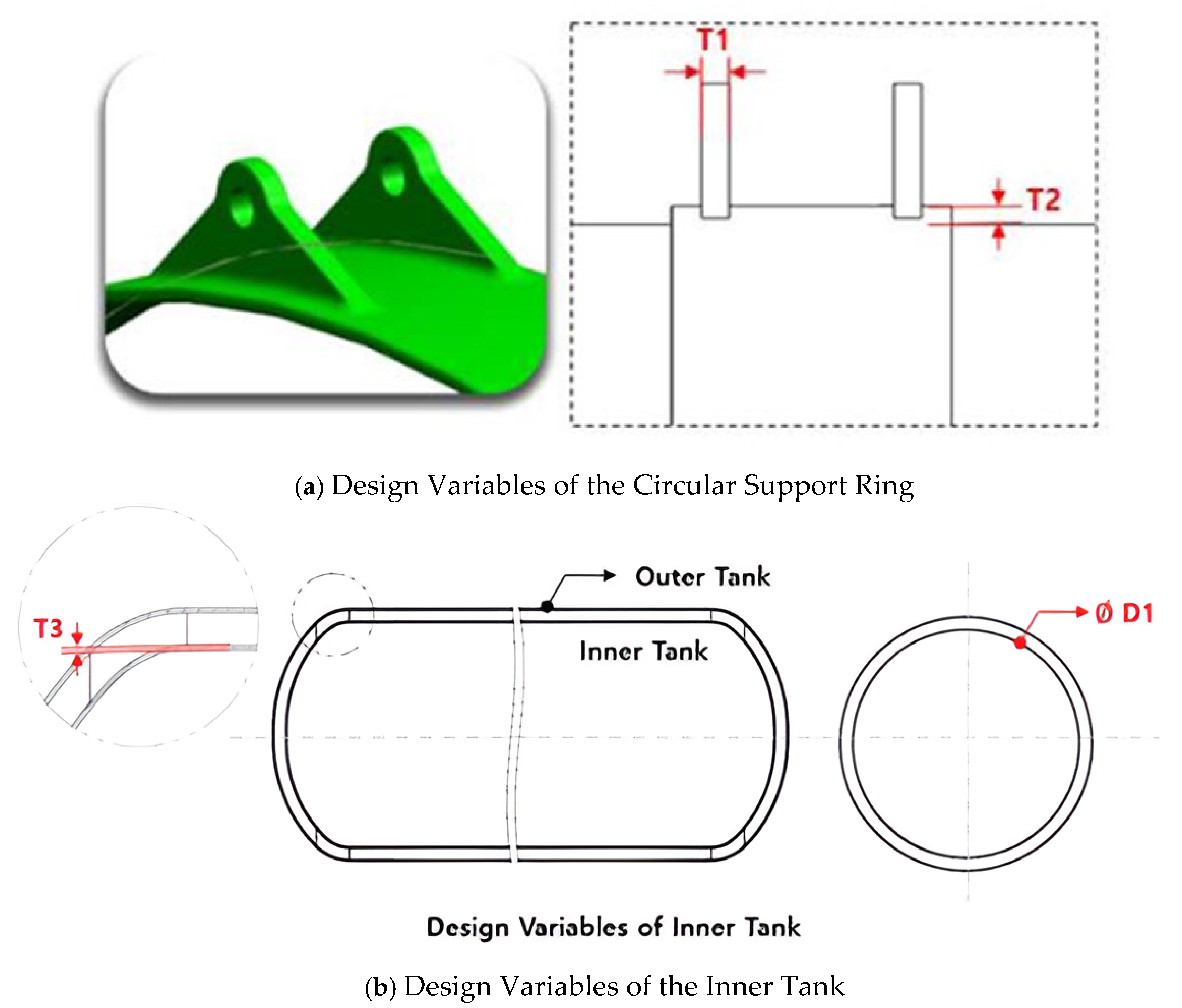
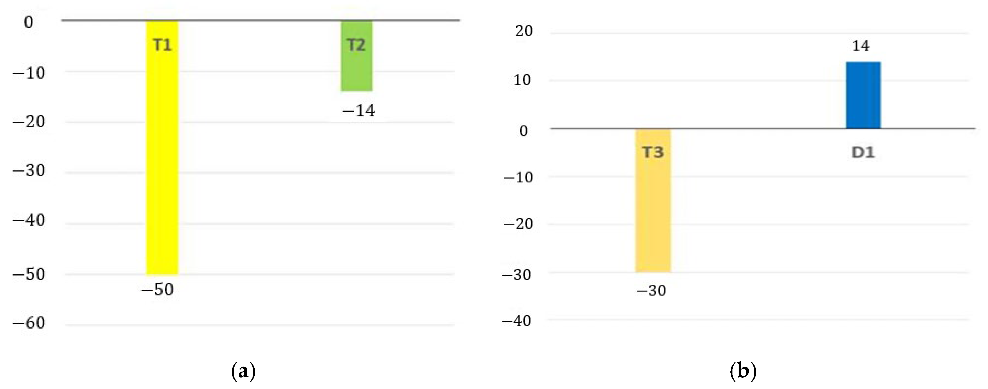
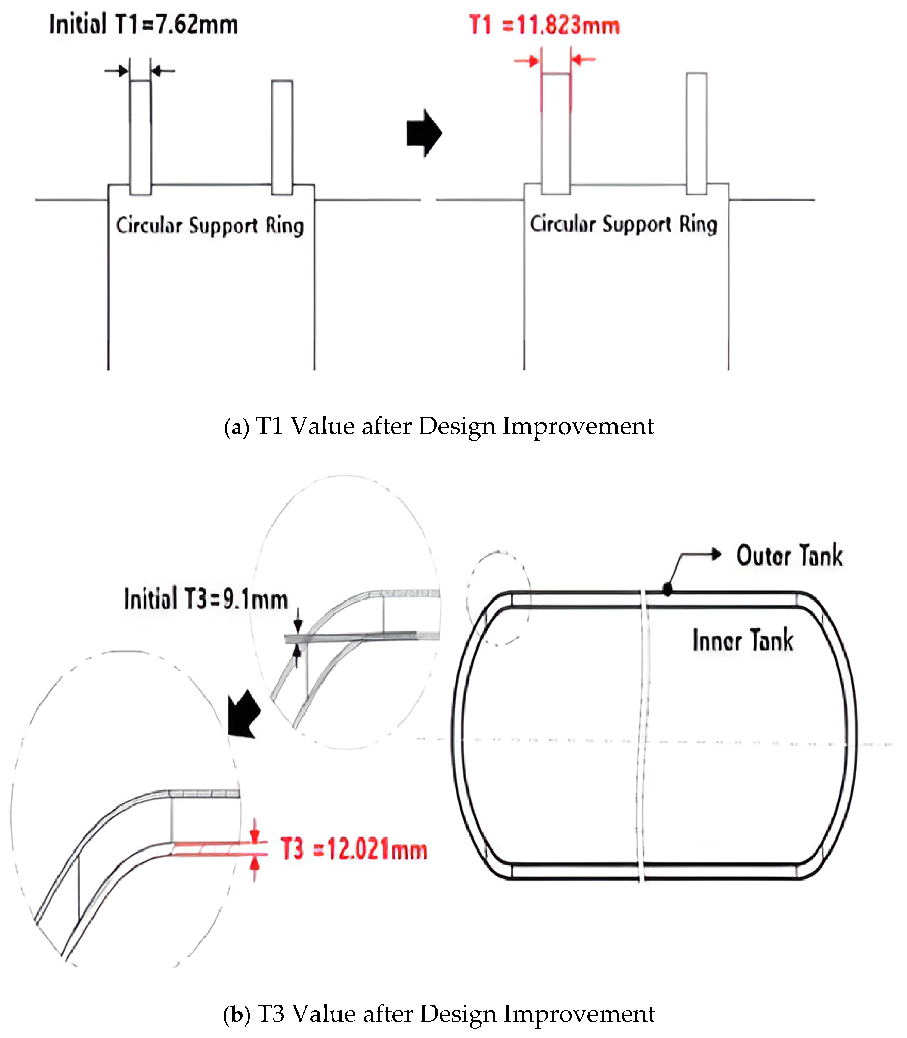
Figure 21b do not meet the target life, structural improvements are necessary to reduce stresses and ensure fatigue life. To decrease the stress in each structure, the dimensions (thickness) of their constituent components must be efficiently increased. To this end, design variables requiring structural reinforcement were selected, and sensitivity analysis was performed.
6. Conclusions
This study resolves the conflict between geometric symmetry and operational asymmetry in marine LH2 tanks through sensitivity-guided optimization. In this study, fluid–structure interaction analysis of a marine liquid hydrogen storage tank was conducted to analyze the effects of wave-induced liquid sloshing on structural components and propose structural improvement measures to ensure fatigue life. Liquid sloshing caused pressure fluctuations inside the tank, leading to high stresses in the internal and external structures of the hydrogen storage tank. These stresses negatively impacted fatigue life, necessitating structural modifications to meet the target service life.
For efficient structural improvement, sensitivity analysis results using the finite difference method were applied to guide design modifications. In practical industrial applications, it is often impossible to express structural functions as equations incorporating design variables. Therefore, as demonstrated in this study, using sensitivity results for each design variable via the finite difference method enables rapid and efficient design improvements, serving as an alternative to optimization simulations that require significant time and expertise.
In conclusion, this study confirms the necessity of analyzing dynamic behaviors under various external conditions and ensuring safety during the design phase of liquid hydrogen storage tanks. In particular, pre-ensuring fatigue life is critical for long-term stable operation in irregular marine environments. The findings of this research are expected to provide practical guidance for structural design and fatigue life improvement of liquid hydrogen storage tanks.
Although this study provides valuable insights into the fatigue life analysis and structural optimization of marine liquid hydrogen storage tanks, there are still several limitations that need to be further explored in subsequent research. Firstly, the fatigue life prediction is based on the S-N curve at −50 °C. Although relevant studies have been cited to indicate that low temperatures can enhance the fatigue performance of 316 L stainless steel, and the possible increase in the wall temperature of actual storage tanks has been taken into account, it still does not fully reflect the material behavior in the extreme low-temperature environment of liquid hydrogen (−253 °C). Secondly, the load conditions are relatively simplified, only considering the impact acceleration in a single direction, and do not cover the complex working conditions such as multi-directional wave excitation, resonant sway and thermal cycling in the actual Marine environment. This study relies entirely on numerical simulation, and the reliability of the simulation results has not yet been verified through experiments. Meanwhile, only one type of tank geometry and material combination was analyzed, and the influences of different support forms, material types or tank shapes were not compared. These limitations have pointed out directions for subsequent research, including conducting full-temperature range fatigue tests, multi-physics field coupling simulations, and multi-parameter optimization comparisons, etc., to further enhance the design reliability and safety of liquid hydrogen storage tanks in real marine environments.
