
Type-2 Fuzzy-Controlled Air-Cleaning Mobile Robot †

Abstract
1. Introduction
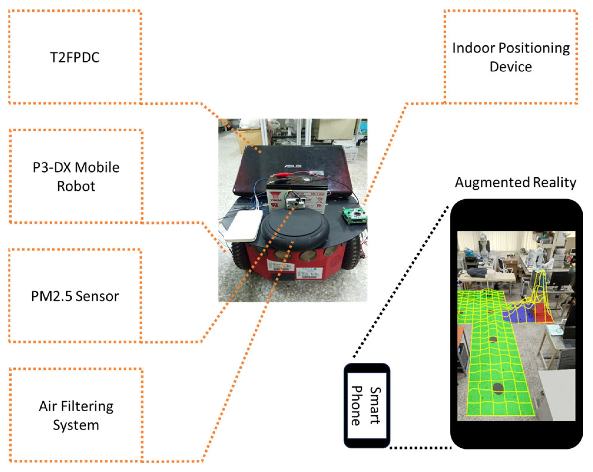
2. Air-Cleaning Mobile Robot
2.1. Mobile Robot Platform
2.2. Air Filtering System
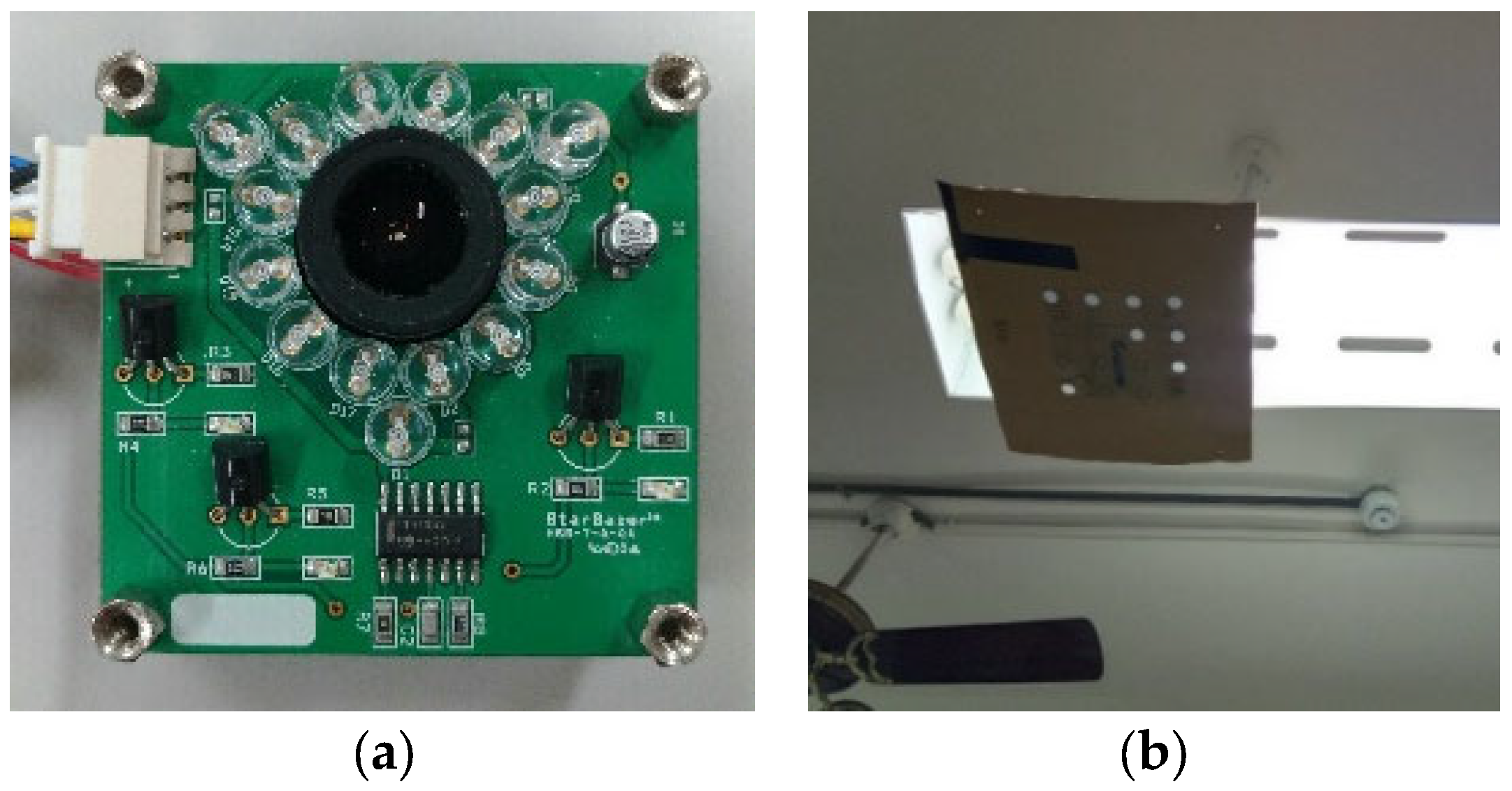
2.3. Sonar Sensors
3. Wall-Following Control of the AMR
3.1. Error Notation
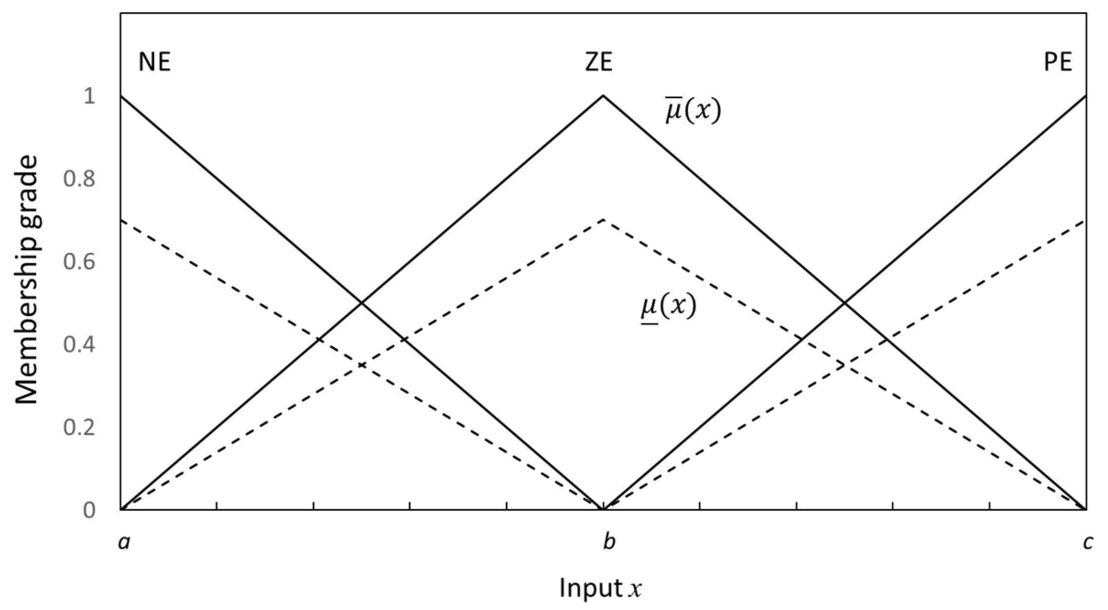
3.2. Type-2 Fuzzy Logic System
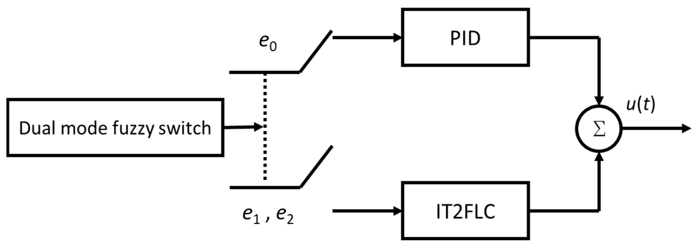
3.3. Type-2 Fuzzy-PID Dual-Mode Controller
3.3.1. Controller Design Art
3.3.2. IT2FLC for Wall Following
3.3.3. PID Controller for Distance Keeping
4. System Implementation
4.1. Indoor Positioning System
4.2. Hardware and Software Settings for the AR System
4.3. T2FPDC Implementation
5. Experimental Results
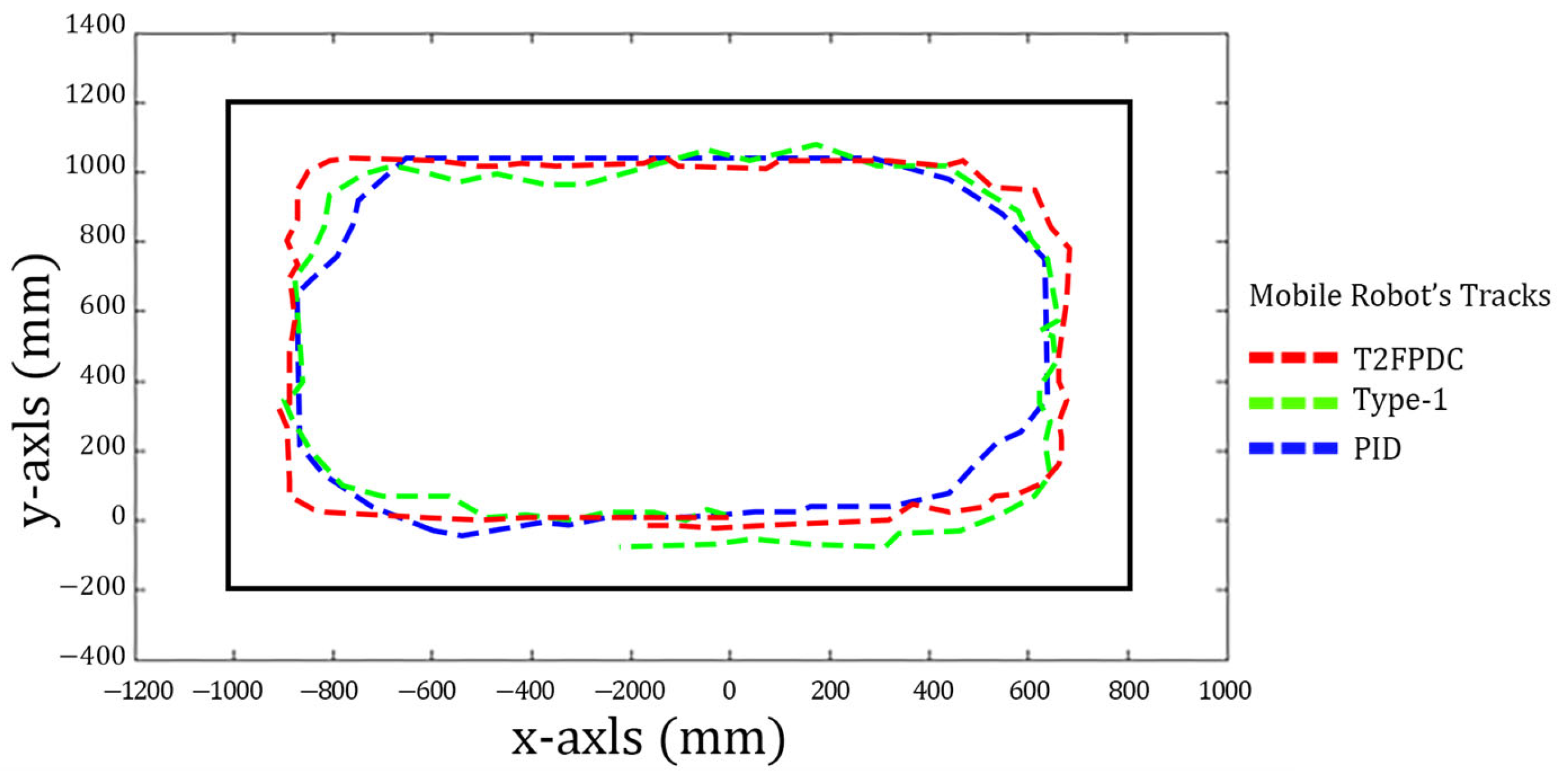
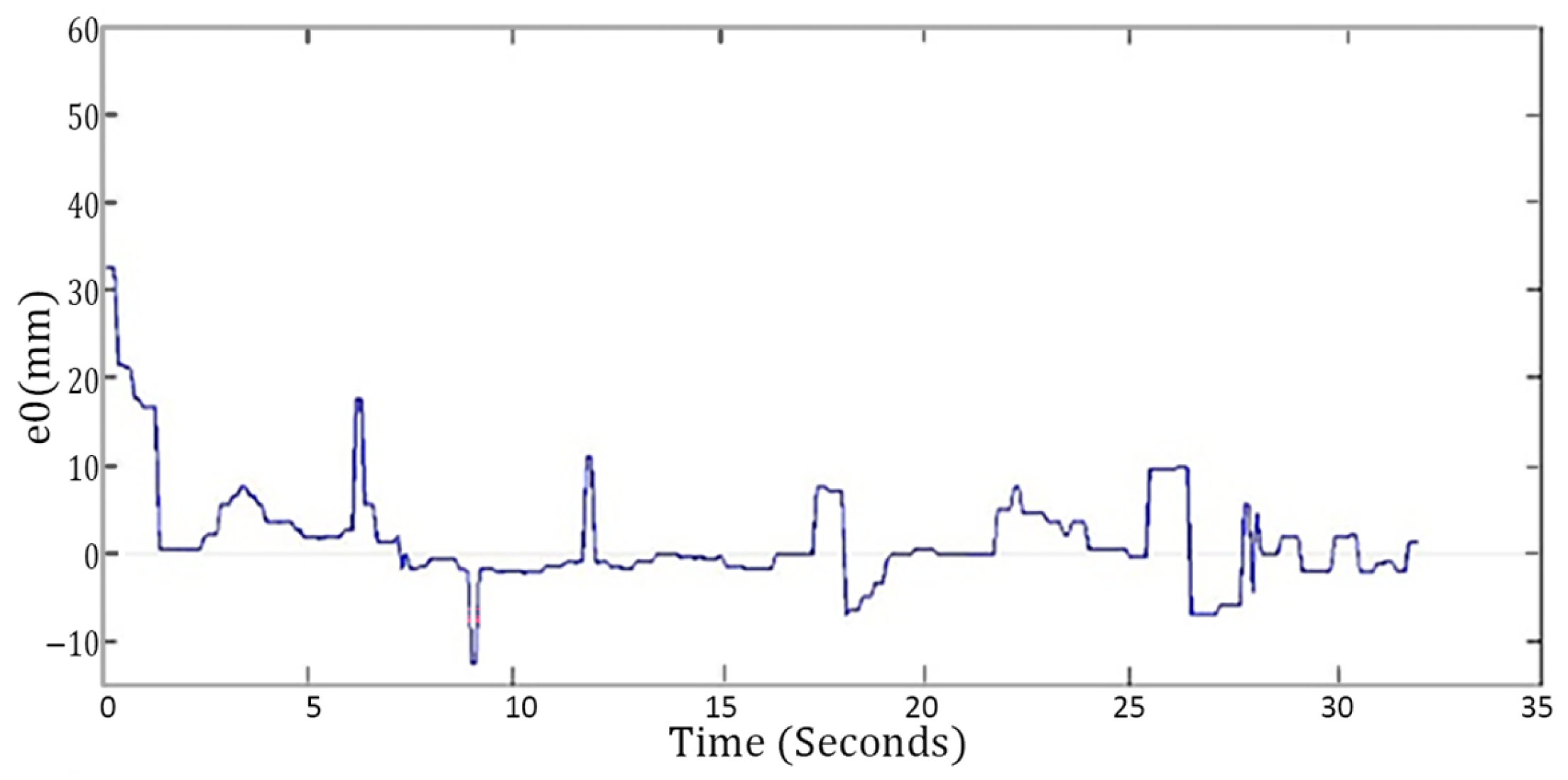
5.1. Controller Validation
- Motion inside a rectangular room without obstacles;
- Motion inside a rectangular room with a single obstacle;
- Following the outside perimeter of a rectangular room with two obstacles.
5.2. Demonstration of AR Display
5.3. Function Verification of Active Air Filtering System
6. Conclusions
Author Contributions
Funding
Data Availability Statement
Conflicts of Interest
Appendix A. Table of Symbols
| Symbol | Definition |
| average moving speed of robot | |
| speed difference between the right and left wheels | |
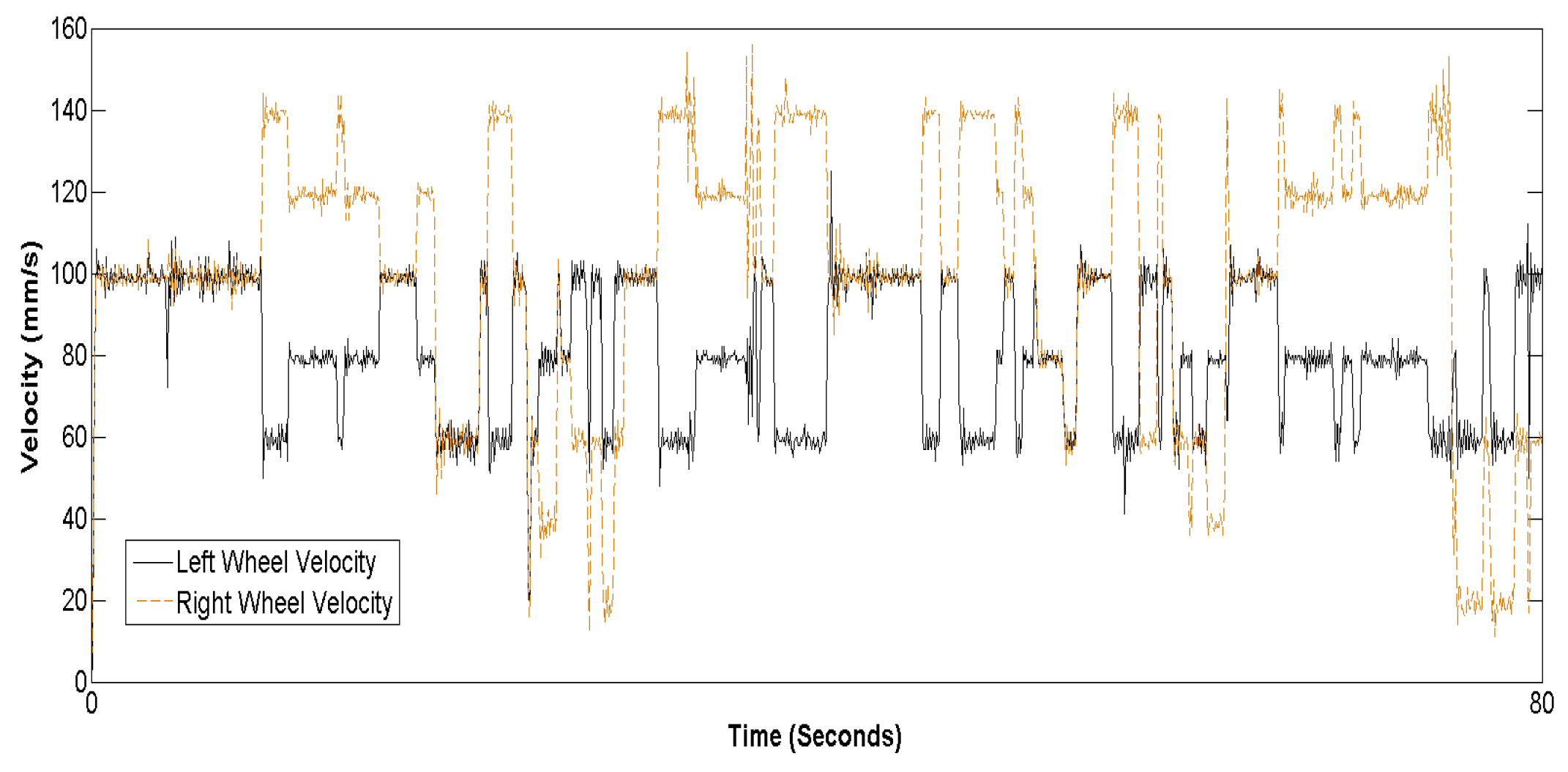
| speed on the left and right wheels | |
| body angle of the robot | |
| ( | coordinator of the robot |
| distance between the two drive wheels | |
| sampling time period | |
| Value of -th sonar sensor | |
| switching threshold for dual-mode control | |
| reference value for | |
| error for wall following | |
| interval type-2 fuzzy sets | |
| upper membership function for type-2 fuzzy set | |
| lower membership function for type-2 fuzzy set | |
| relative parameter between upper and lower membership functions | |
| a, b, c | parameters of interval type-2 membership functions in Figure 3 |
| the center of the fuzzy set | |
| proportional gain of PID controller | |
| integral gain of PID controller | |
| derivative gain of PID controller | |
| NE, ZE, PE | interval type-2 fuzzy sets. |
| B, Z, F | fuzzy sets for wheel speed |
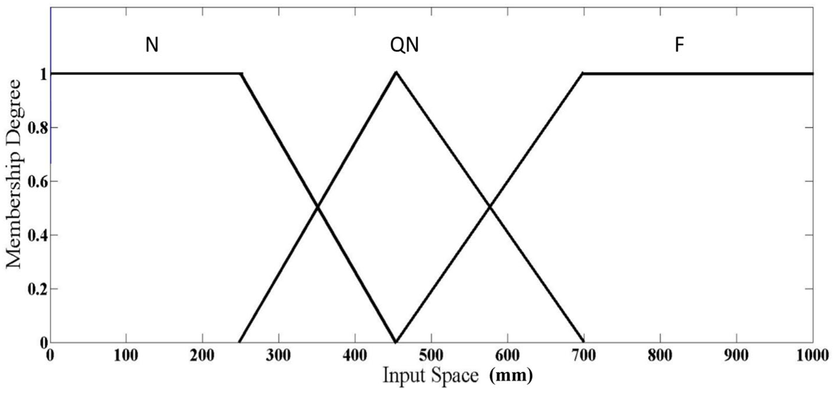
| N, QN, F | Fuzzy sets for distances DL, DF, and DR |
| BF, B, Z, F, FF | fuzzy sets for wheel speed in type-1 FLC |
References
- Cohen, A.J.; Brauer, M.; Burnett, R.; Anderson, H.R.; Frostad, J.; Estep, K.; Balakrishnan, K.; Brunekreef, B.; Dandona, L.; Dandona, R.; et al. Estimates and 25-year trends of the global burden of disease attributable to ambient air pollution: An analysis of data from the global burden of diseases study 2015. Lancet 2017, 389, 1907–1918. [Google Scholar] [CrossRef]
- Robert, B.; Nallathambi, G. A concise review on electrospun nanofibres/nanonets for filtration of gaseous and solid constituents (PM2.5) from polluted air. Colloid Interface Sci. Commun. 2020, 37, 100275. [Google Scholar] [CrossRef]
- Morawska, L.; Thai, P.K.; Liu, X.; Asumadu-Sakyi, A.; Ayoko, G.; Bartonova, A.; Bedini, A.; Chai, F.; Christensen, B.; Dunbabin, M.; et al. Applications of low-cost sensing technologies for air quality monitoring and exposure assessment: How far have they gone? Environ. Int. 2018, 116, 286–299. [Google Scholar] [CrossRef]
- Nižetić, S.; Šolić, P.; López-de-Ipiña González-de-Artaza, D.; Patrono, L. Internet of Things (IoT): Opportunities, issues and challenges towards a smart and sustainable future. J. Clean. Prod. 2020, 274, 122877. [Google Scholar] [CrossRef]
- Katsiokalis, M.; Tsekeri, E.; Lilli, A.; Gobakis, K.; Kolokotsa, D.; Mania, K. GoNature AR: Air quality & noise visualization through a multimodal and interactive augmented reality experience. In Proceedings of the 2023 ACM International Conference on Interactive Media Experiences, Nantes, France, 12–15 June 2023; pp. 366–369. [Google Scholar]
- Jin, M.; Liu, S.; Schiavon, S.; Spanos, C. Automated mobile sensing: Towards high-granularity agile indoor environmental quality monitoring. Build. Environ. 2018, 127, 268–276. [Google Scholar] [CrossRef]
- Veselov, G.E.; Sklyarov, A.A. Nonlinear control system of mobile robot for avoiding obstacles. In Proceedings of the 2019 III International Conference on Control in Technical Systems (CTS), St. Petersburg, Russia, 30 October–1 November 2019; pp. 281–284. [Google Scholar] [CrossRef]
- Li, J.; Wang, J.; Peng, H.; Hu, Y.; Su, H. Fuzzy-torque approximation-enhanced sliding mode control for lateral stability of mobile robot. IEEE Trans. Syst. Man Cybern. Syst. 2022, 52, 2491–2500. [Google Scholar] [CrossRef]
- Gökbulut, M.; Top, A. Real-time deep learning-based position control of a mobile robot. Eng. Appl. Artif. Intell. 2024, 138, 109373. [Google Scholar] [CrossRef]
- Sierra-Garcia, J.E.; Santos, M. Combining reinforcement learning and conventional control to improve automatic guided vehicles tracking of complex trajectories. Expert Syst. 2024, 41, e13076. [Google Scholar] [CrossRef]
- Abdelwahab, M.; Parque, V.; Fath Elbab, A.M.R.; Abouelsoud, A.A.; Sugano, S. Trajectory tracking of wheeled mobile robots using z-number based fuzzy logic. IEEE Access 2020, 8, 18426–18441. [Google Scholar] [CrossRef]
- Batti, H.; Jabeur, C.B.; Fourati, H.; Seddik, H. Fuzzy logic based control for autonomous mobile robot navigation and obstacles avoidance. In Proceedings of the 2022 IEEE Information Technologies & Smart Industrial Systems (ITSIS), Paris, France, 15–17 July 2022; pp. 1–6. [Google Scholar] [CrossRef]
- Xu, Q.; Kan, J.; Chen, S.; Yan, S. Fuzzy PID based trajectory tracking control of mobile robot and its simulation in Simulink. Int. J. Control. Autom. 2014, 7, 233–244. [Google Scholar] [CrossRef]
- Tiep, D.K.; Lee, K.; Im, D.-Y.; Kwak, B.; Ryoo, Y.-J. Design of Fuzzy-PID Controller for Path Tracking of Mobile Robot with Differential Drive. Int. J. Fuzzy Log. Intell. Syst. 2018, 18, 220–228. [Google Scholar] [CrossRef]
- Wondosen, A.; Shiferaw, D. Fuzzy Logic Controller Design for Mobile Robot Outdoor Navigation. arXiv 2024, arXiv:2401.01756. [Google Scholar]
- Hanafi, D.; Abueejela, Y.M.; Zakaria, M.F. Wall follower autonomous robot development applying fuzzy incremental controller. Intell. Control. Autom. 2013, 4, 18–25. [Google Scholar] [CrossRef]
- Zaki, A.A.; Mulyana, E.; Mardiati, R. Modeling wall tracer robot motion based on fuzzy logic control. In Proceedings of the 2020 6th International Conference on Wireless and Telematics (ICWT), Bandung, Indonesia, 3–4 September 2020; pp. 1–6. [Google Scholar] [CrossRef]
- Chen, C.-H.; Jeng, S.-Y.; Lin, C.-J. Mobile robot wall-following control using fuzzy logic controller with improved differential search and reinforcement learning. Mathematics 2020, 8, 1254. [Google Scholar] [CrossRef]
- Suwoyo, H.; Tian, Y.; Deng, C.; Adriansyah, A. Improving a wall-following robot performance with a PID-genetic algorithm controller. In Proceedings of the 2018 5th International Conference on Electrical Engineering, Computer Science and Informatics (EECSI), Malang, Indonesia, 16–18 October 2018; pp. 314–318. [Google Scholar] [CrossRef]
- Riman, C.F.; Abi-Char, P.E. Fuzzy logic control for mobile robot navigation in automated storage. Int. J. Mech. Eng. Robot Res. 2023, 12, 313–323. [Google Scholar] [CrossRef]
- Cherroun, L.; Nadour, M.; Kouzou, A. Type-1 and type-2 fuzzy logic controllers for autonomous robotic motion. In Proceedings of the 2019 International Conference on Applied Automation and Industrial Diagnostics (ICAAID), Elazig, Turkey, 25–27 September 2019; pp. 1–5. [Google Scholar] [CrossRef]
- Thuong, T.T.; Ha, V.T.; Truc, L.N. Intelligent control for mobile robots based on fuzzy logic controller. In Intelligent Systems and Networks. ICISN 2023; Lecture Notes in Networks and Systems; Springer: Berlin/Heidelberg, Germany, 2023; Volume 752, pp. 566–573. [Google Scholar] [CrossRef]
- Al-Mahturi, A.; Santoso, F.; Garratt, M.A.; Anavatti, S.G. A Novel Evolving Type-2 Fuzzy System for Controlling a Mobile Robot under Large Uncertainties. Robotics 2023, 12, 40. [Google Scholar] [CrossRef]
- Juang, C.-F.; Huang, C.-H. Reinforcement ant optimized fuzzy controller for mobile-robot wall-following control. IEEE Trans. Ind. Electron. 2009, 56, 3931–3940. [Google Scholar] [CrossRef]
- Hsu, C.-H.; Juang, C.-F. Evolutionary robot wall-following control using type-2 fuzzy controller with species-de-activated continuous ACO. IEEE Trans. Fuzzy Syst. 2013, 21, 100–112. [Google Scholar] [CrossRef]
- Santiago, C.; Chiu, C.-S. Interval type-2 fuzzy and PID dual-mode controller for an autonomous mobile robot. In Proceedings of the 2018 International Conference on System Science and Engineering (ICSSE), New Taipei, Taiwan, 28–30 June 2018; pp. 1–6. [Google Scholar] [CrossRef]
- Al-Mallah, M.; Ali, M.; Al-Khawaldeh, M. Obstacles avoidance for mobile robot using type-2 fuzzy logic controller. Robotics 2022, 11, 130. [Google Scholar] [CrossRef]
- Fareh, R.; Baziyad, M.; Rabie, T.; Bettayeb, M. Enhancing path quality of real-time path planning algorithms for mobile robots: A sequential linear paths approach. IEEE Access 2020, 8, 167090–167104. [Google Scholar] [CrossRef]
- Mendel, J.M.; John, R.I.B. Type-2 fuzzy sets made simple. IEEE Trans. Fuzzy Syst. 2002, 10, 117–127. [Google Scholar] [CrossRef]
- Chen, C.; Wu, D.; Garibaldi, J.M.; John, R.I.; Twycross, J.; Mendel, J.M. A comprehensive study of the efficiency of type-reduction algorithms. IEEE Trans. Fuzzy Syst. 2021, 29, 1556–1566. [Google Scholar] [CrossRef]
- Chen, Y. Study on centroid type-reduction of interval type-2 fuzzy logic system based on noniterative algorithms. Complexity 2019, 9, 7325053. [Google Scholar] [CrossRef]
- El-Nagar, A.M.; El-Bardini, M. Simplified interval type 2 fuzzy logic system based on new type-reduction. J. Intell. Fuzzy Syst. 2014, 27, 1999–2010. [Google Scholar] [CrossRef]
- Huang, J.; Junginger, S.; Liu, H.; Thurow, K. Indoor positioning systems of mobile robots: A Review. Robotics 2023, 12, 47. [Google Scholar] [CrossRef]
- Sanità, M.; Fratini, J.; Muralikrishna, N.; Pierdicca, R.; Malinverni, E.S. Augmented reality for air quality monitoring: Case study in the marche region (Italy). Int. Arch. Photogramm. Remote Sens. Spat. Inf. Sci. 2024, 48, 389–395. [Google Scholar] [CrossRef]


| Methods | Adaptability | Computational Complexity | Robustness | Drawback/ Advantage |
|---|---|---|---|---|
| Fuzzy-PID | Low | Low | Low | Simple structure |
| Type-1 FLC | Low | Medium | Medium | High rule sensitivity |
| Type-2 FLC | High | High | High | Low rule sensitivity |
| Hybrid FLC | Medium | High | Medium | Difficult design |
| Rule | ||||
|---|---|---|---|---|
| 1 | NE | NE | F | B |
| 2 | NE | ZE | F | Z |
| 3 | NE | PE | F | Z |
| 4 | ZE | NE | F | B |
| 5 | ZE | ZE | F | F |
| 6 | ZE | PE | Z | F |
| 7 | PE | NE | F | Z |
| 8 | PE | ZE | Z | F |
| 9 | PE | PE | Z | F |
| Rule | DL | DF | DR | ||
|---|---|---|---|---|---|
| 1 | N | N | N | BF | BF |
| 2 | N | N | QN | FF | BF |
| 3 | N | N | F | FF | BF |
| 4 | N | QN | N | F | F |
| 5 | N | QN | QN | FF | Z |
| 6 | N | QN | F | FF | BF |
| 7 | N | F | N | F | F |
| 8 | N | F | QN | F | B |
| 9 | N | F | F | FF | BF |
| 10 | QN | N | N | BF | FF |
| 11 | QN | N | QN | BF | FF |
| 12 | QN | N | F | FF | BF |
| 13 | QN | QN | N | B | FF |
| 14 | QN | QN | QN | Z | FF |
| 15 | QN | QN | F | FF | B |
| 16 | QN | F | N | B | F |
| 17 | QN | F | QN | Z | FF |
| 18 | QN | F | F | FF | Z |
| 19 | F | N | N | BF | FF |
| 20 | F | N | QN | BF | FF |
| 21 | F | N | F | BF | FF |
| Controller | Variance | Mean Settling Time (s) | |
|---|---|---|---|
| PID | 13.1 | 9.1 | 2 |
| Type-1 FLC | 6.2 | 12.7 | 3.7 |
| T2FPDC | 3.8 | 4.1 | 2.1 |
Disclaimer/Publisher’s Note: The statements, opinions and data contained in all publications are solely those of the individual author(s) and contributor(s) and not of MDPI and/or the editor(s). MDPI and/or the editor(s) disclaim responsibility for any injury to people or property resulting from any ideas, methods, instructions or products referred to in the content. |
© 2025 by the authors. Licensee MDPI, Basel, Switzerland. This article is an open access article distributed under the terms and conditions of the Creative Commons Attribution (CC BY) license (https://creativecommons.org/licenses/by/4.0/).
Share and Cite
Chiu, C.-S.; Yao, S.-Y.; Santiago, C. Type-2 Fuzzy-Controlled Air-Cleaning Mobile Robot. Symmetry 2025, 17, 1088. https://doi.org/10.3390/sym17071088
Chiu C-S, Yao S-Y, Santiago C. Type-2 Fuzzy-Controlled Air-Cleaning Mobile Robot. Symmetry. 2025; 17(7):1088. https://doi.org/10.3390/sym17071088
Chicago/Turabian StyleChiu, Chian-Song, Shu-Yen Yao, and Carlo Santiago. 2025. "Type-2 Fuzzy-Controlled Air-Cleaning Mobile Robot" Symmetry 17, no. 7: 1088. https://doi.org/10.3390/sym17071088
APA StyleChiu, C.-S., Yao, S.-Y., & Santiago, C. (2025). Type-2 Fuzzy-Controlled Air-Cleaning Mobile Robot. Symmetry, 17(7), 1088. https://doi.org/10.3390/sym17071088