Article

A Strategy for Improving Millimeter Wave Communication Reliability by Hybrid Network Considering Rainfall Attenuation

1
College of Information Engineering, Yangzhou University, Yangzhou 225009, China
2
College of Civil Science and Engineering, Yangzhou University, Yangzhou 225009, China
*
Author to whom correspondence should be addressed.
Symmetry 2025, 17(7), 1054; https://doi.org/10.3390/sym17071054
Submission received: 28 April 2025 / Revised: 27 May 2025 / Accepted: 25 June 2025 / Published: 3 July 2025
(This article belongs to the Special Issue Symmetry/Asymmetry in Future Wireless Networks)

Abstract

With the rapid development of smart connected vehicles, vehicle network communications demand high-speed data transmission to support advanced automotive services. Millimeter Wave (mmWave) communication offers fast data rates, strong anti-interference capabilities, high precision localization and low-latency, making it suitable for high-speed in-vehicle communications. However, mmWave communication performance in vehicular networks is hindered by high path loss and frequent beam alignment updates, significantly degrading the coverage and connectivity of vehicle nodes (VNs). In addition, atmospheric propagation attenuation further deteriorates signal quality and limits system performance due to raindrop absorption and scattering. Therefore, the pure mmWave networks cannot meet the high requirements of highway vehicular communications. To address these challenges, this paper proposes a hybrid mmWave and microwave network architecture to improve VNs’ coverage and connectivity performances through the strategic deployment of Roadside Units (RSUs). Using Radio Access Technology (RAT), mmWave and microwave RSUs are symmetrically deployed on both sides of the road to communicate with VNs located at the road center. This symmetric RSUs deployment significantly improves the network reliability. Analytical expressions for coverage and connectivity in the proposed hybrid networks are derived and compared with the pure mmWave networks, accounting for rainfall attenuation. The study results show that the proposed hybrid network shows better performance than the pure mmWave network in both coverage and connectivity.

1. Introduction

In recent years, in-vehicle networks have emerged as a popular research area, attracting significant attention from both automotive and telecommunications industries. While road safety remains the primary focus of the automotive industry, the integration of wireless communication technologies has driven the development of Vehicle-to-Everything (V2X) communications [1]. V2X enables data exchange between vehicles and roadside transportation infrastructure to ensure road safety [2], provide traffic management [3] and offer additional services such as entertainment applications [4]. Among the V2X technologies, vehicle-to-infrastructure (V2I) communication is widely used to support enhanced mobile broadband (eMBB) and ultra-reliable low-latency communication (URLLC) services, while eMBB requires ultra-high data rates, URLLC requires extremely low latency and ultra-high reliability [5,6]. Currently, V2I communication relies on Long Term Evolution (LTE) connectivity in sub-6 GHz frequency bands, providing reliable connectivity with data rates of up to 100 Mbps in high mobility scenarios [7].
However, autonomous driving systems demand even more advanced services with higher data rates. mmWave radio access technology emerges as a promising solution, and it offers an available spectrum in the 10 to 300 GHz range that can effectively support high-speed data transmission requirements [8]. In addition, mmWave offers inherent communication security advantages due to its relatively narrow beamwidth [9]. Despite these benefits, mmWave systems face several challenges. High path loss limits their coverage range, and as the density of RSUs increases, connectivity between the vehicle nodes (VNs) and serving Roadside Units (RSUs) decreases over time. Rainfall further impacts mmWave communications quality by introducing fading and multi-path effects, which lead to signal degradation. These phenomena cause sudden drops in received signal strength and can result in serious system outages. In order to improve the coverage and connectivity of V2X communication to ensure both high speed and reliability, this paper proposes a hybrid mmWave and microwave network architecture for highway vehicular communication in rainfall environments.

1.1. Related Work

Since mmWave communication has the capability to provide exceptionally high data rates, numerous studies have analyzed the performance of mmWave vehicular networks. Previous research has extensively investigated the coverage and connectivity probability of mmWave networks [10,11,12]. The research in [10] proposed a self-organizing grid-based network coverage model for urban vehicle environments. Using a wire process-based approach, this work demonstrated how urban infrastructure affects signal propagation and subsequently analyzed network coverage. Similarly, ref. [11] analyzed the connectivity in mmWave vehicular networks, emphasizing the trade-offs between beamforming gains and mobility-induced link disruptions in both urban and rural highway scenarios. Ref. [12] studied imperfect beam alignment in mmWave cellular networks, demonstrating its effect on coverage probability. By employing an augmented antenna model, the directional gain under imperfect beam alignment was obtained as a discrete random variable. Consequently, a computationally tractable expression for the coverage probability of a mmWave cellular network was obtained. Ref. [13] extended this analysis to massive MIMO systems by comparing different beamforming schemes for improved cell-edge performance. It investigated the ability of orthogonal random precoding (ORP) and minimum mean square error (MMSE) receivers to extend cell coverage and enhance sum-rate performance for cell-edge users. Moreover, Ref. [14] examined downlink cellular vehicle-to-everything (C-V2X) communication, showing that hybrid spectrum usage can significantly enhance coverage in dense vehicular scenarios.
To enable reliable V2X communication links with enhanced data rates between mobile vehicles and mmWave base stations, efficient beam alignment is essential. Addressing this need, Ref. [15] introduced an innovative beam alignment approach that integrates a 128-filter convolutional neural network (CNN) with a 4-layer bidirectional long short-term memory (BiLSTM) network. This hybrid deep learning-based model demonstrates superior performance in beam alignment accuracy compared with conventional machine learning algorithms. In the context of high-throughput mmWave communications, Ref. [16] presented a novel VANET architecture incorporating attached flying platforms. This study employed stochastic geometry analysis to evaluate the system’s capability in addressing urban connectivity challenges, deriving closed-form expressions for both outage probabilities and average achievable rates to comprehensively assess network performance. Ref. [17] proposed a hybrid beamforming scheme based on the MMSE criterion, demonstrating optimized performance for multi-user mmWave communication systems.
Recent research has demonstrated significant advancements in mmWave vehicular networks through the integration of intelligent reflecting surfaces (IRS) and artificial intelligence (AI) techniques. Ref. [18] optimized joint power allocation and user association in IRS-assisted mmWave systems. This system utilized sequential fractional programming (SFP) to optimize the IRS passive beam-forming configuration and solved the power allocation issue using standard convex optimization to extend the mmWave signal coverage to traditionally blind spots. Ref. [19] studied a dual-hop hybrid IRS for outdoor-to-indoor mmWave communications, improving coverage in obstructed environments. Ref. [20] applied deep reinforcement learning (DRL) for D2D relay selection and power allocation in mmWave vehicular networks. Building upon these AI-driven solutions, Ref. [21] further extended the DRL for energy-efficient secure communications in mmWave VANETs.
In addition, to achieve High-Throughput Ultra-Reliable Low-Latency Communication (HT-URLLC), Ref. [22] proposed a dual time-slot Medium Access Control (MAC) scheme incorporating a scheduling alignment mechanism. This solution was implemented in a hybrid mmWave/Sub-6 GHz network architecture, where the novel linear topology and scheduling protocol simultaneously addressed mmWave utility challenges while demonstrating strong potential for HT-URLLC realization. Ref. [23] investigated mmWave V2I links impairments caused by road bridge blockage in urban environments, and gave an empirical model that accurately characterizes these bridge blockage effects. In a related approach, Ref. [24] proposed a deep learning-based path loss prediction model that considered the urban road obstacles conditions in mmWave communication, and built a realistic simulation environment and collected data to train the proposed deep learning model.
However, mmWave communication still faces some limitations, including directional link constraints and high path loss, which significantly restrict its coverage range. Recent studies have addressed these challenges through hybrid network architectures combining mmWave with complementary technologies. Ref. [25] established the first systematic tutorial on integrated mmWave- μ W communications, which synergistically combined the long-range reliability of μ W-band transmissions with the high-speed directional capabilities of mmWave frequencies. Through comprehensive analysis, the work presented fundamental theoretical results and practical insights that collectively demonstrate the significant advantages of this hybrid communication framework. Ref. [26] proposed a hybrid D2D network model, demonstrating improved reliability by switching between mmWave and microwave links. Ref. [27] enhanced connectivity in hybrid vehicular networks through intelligent resource allocation. Ref. [28] introduced hybrid mmWave systems as a paradigm for heterogeneous networks (HetNets), emphasizing seamless handover between frequency bands. The study [29] investigated capacity-based multi-correlation in hybrid Ultra-High Frequency (UHF) and mmWave networks. It allowed mobile users to simultaneously connect to multiple UHF small cell (SCells) sites, mmWave SCells, and/or UHF macro cell sites, demonstrating superior data rates and energy efficiency compared to conventional technologies.
From the above existing studies analysis, it is easy to find that all these studies fail to address how the integration of microwave links can enhance mmWave communication performance, and no related research has considered the weather (e.g., rainfall) impacts on network reliability. To bridge this gap, this paper proposes a hybrid mmWave-microwave network architecture that leverages the complementary advantages of both technologies to improve coverage and connectivity for highway vehicular networks in rainfall scenarios.

1.2. Contributions of This Article

Pure mmWave vehicular networks offer a high data rate, but they suffer from limited coverage, connectivity, and significant weather-induced performance degradation compared with microwave networks. To address these challenges, we propose a novel hybrid mmWave and microwave architecture that combines the broad coverage of microwave networks with the high-speed capabilities of mmWave communications. The main contributions of this paper are summarized as follows.
  • We propose a hybrid vehicular network architecture for urban highway that integrates mmWave and microwave networks. The mmWave communication units are deployed along one roadside following a one-dimensional uniform Poisson Point Process ( P P P ), while microwave units are deployed on the other side of the road. The hybrid architecture simultaneously achieves high-speed connectivity and maximum coverage probability. Analytical expressions for both coverage probability and network connectivity are derived for the proposed hybrid mmWave-microwave system.
  • A rainfall attenuation model is established to describe its impacts on the performance. We analyze the frequency-dependent attenuation coefficient under varying rain intensities and formulate a rainfall-induced path loss model. Furthermore, the effects of rainfall attenuation on the path loss and coverage in mmWave networks are also determined.
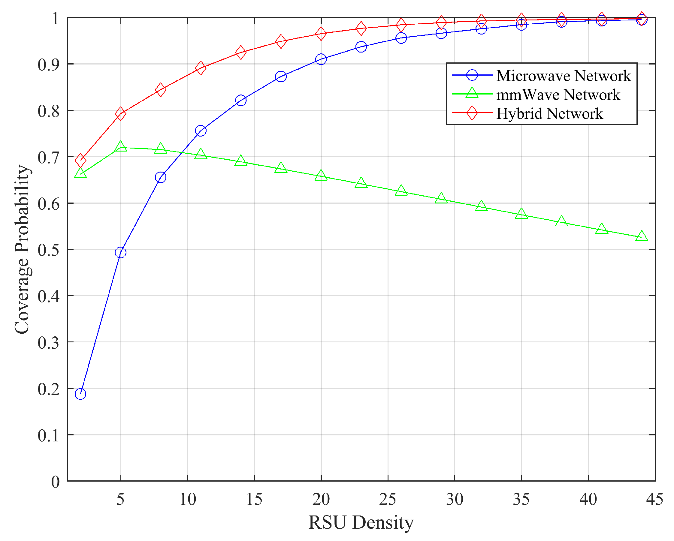
  • The proposed hybrid network is compared with pure mmWave and pure microwave networks in terms of coverage probability and connectivity. The impact of various parameters on performance is analyzed. The results show that the hybrid network outperforms the pure mmWave network in both coverage probability and connectivity.
The rest of the paper is organized as follows. Section 2 introduces the system model. Section 3 derives the coverage and connectivity expressions for the system. Section 4 presents the simulation setting and analyzes the numerical results. Finally, Section 5 concludes the work and points out the future work direction.

2. System Model

This section presents the system models employed to evaluate the reliability of the proposed hybrid network, with a focus on coverage and connectivity enhancement considering rainfall attenuation. First, the hybrid system architecture is introduced, followed by the SINR and antenna model and beam tracking designed to improve system reliability.

2.1. The Proposed Hybrid Network Modeling

The proposed hybrid network architecture is shown in Figure 1, which consists of multiple vehicle nodes (VNs), mmWave RSUs, and microwave RSUs that are deployed symmetrically on each side of the highway.
Assume that the highway road consists of N lanes per direction, with each lane of width w, so the total road width per direction is W = w N , and the total road width with two opposite directions is 2 W . Suppose there are N = 2 lanes in one direction, one is the outer obstacle lane and the other is the inner car lane, also the inner car lane is designated for fast-moving cars, and the outer obstacle lane is designated for slow-moving vehicles, as shown in Figure 1.
We also assume that some fixed-height obstacles are randomly placed in the obstacle lane. In our hybrid networks, we place the target mobile VN at the coordinates of the road center O ( 0 , 0 ) , and assume that the VN is connected to the mmWave RSUs, as shown in Figure 1. One side of the road is deployed by mmWave RSUs, such as base stations, which follow a one-dimensional (1−D) Poisson point distribution ( P P P ) φ m with density λ m , and the other outer side is deployed by microwave RSUs, which also follow a 1−D P P P φ μ with density λ μ .
As shown in the Figure 1, each VN initially establishes a connection with its serving mmWave RSU. If the mmWave link is disrupted, the VN maintains connectivity by switching to a microwave RSU. This mechanism forms a hybrid network model that integrates both microwave and mmWave RSUs. The parameter descriptions used in this article are shown in Table 1.

2.2. SINR Calculation

The system reliability is related to the connectivity and coverage performance, with the SINR serving as a critical metric that directly impacts the connectivity and convergence. In general, a higher SINR ensures better connections and broader convergence. The channel between the test VN and its serving RSUs is described as a Rayleigh channel model with a unit mean (i.e., e x p ( 1 ) ). Similarly, to capture the effect of interference on communication performance, the channel between the interfering RSUs and the test VN is modeled as independent and identically distributed ( i . i . d . ). Both mmWave and microwave RSUs are assumed to transmit with a constant power of P t . The corresponding noise power at the receiver is denoted as σ m 2 for mmWave RSUs and σ μ 2 for microwave RSUs, respectively.
The SINR γ m for the reference VN when connected to a mmWave RSU at a distance of r m can be expressed as follows:
γ m = P t g 1 G S L 1 ( r m ) σ m 2 + I m
where interference term I m = j ξ m P t g j G I L j ( r m ) , G S and G I denote the main lobe gain of the mmWave network and the interference link gain, respectively. g 1 and g j denote the channel fading power between the reference VN and its serving mmWave RSUs and interfering mmWave RSUs, respectively. L 1 ( r m ) and L j ( r m ) denote the corresponding path loss functions, which can be obtained from the following (6).
Similarly, the SINR γ μ of the reference VN associated with the microwave RSU at a distance of r μ is given by
γ μ = P t g ^ 1 L 1 ( r μ ) σ μ 2 + I μ
where the microwave interference term I μ = j ξ μ P t g ^ j L j ( r μ ) , g 1 ^ and g j ^ denote the channel fading power between the reference VN and the serving microwave RSUs and the interfering microwave RSUs, respectively. L 1 ( r μ ) and L j ( r μ ) denote the corresponding path loss functions obtained from the following (7).

2.3. Antenna Model and Beam Tracking

The antenna model directly affects the signal strength and interference; higher antenna gain yields a stronger signal and improved SINR. This enhancement directly translates to more reliable communication links and improves system connectivity. Furthermore, the beam tracking dynamically adjusts antenna beams to maintain optimal connectivity and enhance system coverage. Therefore, the antenna model serves as the foundational framework for coverage and SINR performance, while beam tracking ensures the dynamic optimization of antenna gain and beamwidth.
Due to severe path loss in isotropic mmWave transmission, directional beam-forming using antenna arrays is employed on both RSUs and VNs to achieve antenna gain and mitigate this limitation. The mmWave RSU’s beam-forming model approximates a segmented antenna model, which takes into account three parameters: the main lobe beamwidth ( ψ M ), main lobe gain ( G S ), and side lobe gain ( g S ). The effective antenna gain G B ( ψ ) in the direction of a target VN is formulated as a function of the angle ψ with respect to the aperture direction, as follows:
G B ( ψ ) = G s , i f ψ ψ M 2 g s , o t h e r w i s e
In addition, for interfering links, the jamming beam direction follows a uniform distribution within the range of [ 180 , 180 ] . Therefore, the effective antenna gain G s for an interfering link G I follows a probability of P s = ψ M 2 π , g S with probability of p s = 1 ψ M 2 π , and P s denotes the probability of main-lobe alignment.

3. System Reliability Improvement Analysis

In this section, we analyze the system reliability from the path loss, coverage, connectivity and rainfall attenuation aspects. As key factors for the network reliability, both the coverage and connectivity are fundamentally constrained by the communication range of the networks. The mmWave networks offer high data rates but face limitations of coverage and connectivity. Conversely, the microwave has a relatively larger communication range that provides good coverage and connectivity. To leverage the complementary advantages of both technologies, we have developed a hybrid vehicular network architecture that combines mmWave and microwave networks, utilizing the microwave’s broader communication range and the mmWave’s high data rates. In the proposed architecture, the mmWave and microwave RSUs are deployed on opposite sides of the road, the scenario is shown in Figure 1. The microwave RSU density is optimized based on the highest coverage probability, and the mmWave RSUs are deployed complementarily.
The aim of this paper is to focus on environmental factors and key parameters for mmWave vehicular design. First, we establish association rules for VNs and derive the probability density function ( P D F ) of the distance r Q between a VN and its serving RSU considering both LOS and NLOS, where Q = { m , μ } denotes the type of RAT, with m for mmWave and μ for microwave. Second, we derive analytical expressions for the SINR coverage probability and the probability that a mobile VN remains within its serving RUSs’ communication range in a time slot. These derivations enable us to determine the connectivity maintenance probability.
Assume each VN connects to its closest RSU, whether the nearest mmWave RAT or microwave RAT. The P D F of distance r m to the nearest mmWave RSU f M ( r m ) follows the derivation in [11], and can be expressed as follows:
f M ( r m ) = 2 λ m r m b ( r m ) e 2 λ m b ( r m )
And the P D F of the distance r μ to the nearest microwave RSU f μ ( r μ ) is given by the following [11]:
f μ ( r μ ) = 2 λ μ r μ b ( r μ ) e 2 λ μ b ( r μ )
The function b ( i ) = i 2 W 2 , where i { r m , r μ } , and W is the total width of lanes per travel direction. The deployment densities of mmWave and microwave RSUs are denoted by λ m and λ μ , respectively.

3.1. Path Loss Analysis

Path loss is related to the attenuation of a signal as it propagates from the transmitter to the receiver. Usually, a higher path loss leads to lower connectivity and a smaller coverage area. It is necessary to analyze the path loss when improving the system reliability.
We employ a modified path loss model from [30], incorporating both line-of-sight (LOS) and non-line-of-sight (NLOS) propagation conditions. The model distinguishes between two states (denoted as S = { L , N L } ) based on whether obstacles obstruct the link between VNs and serving RSUs.
The path loss function is defined based on the distance r Q as follows [31]: L Q , S ( r Q ) = c 0 r Q 2 + H U 2 α Q , S 2 . Furthermore, S = { L , N L } distinguishes the link state (LOS or NLOS). c 0 = ( λ Q 4 π ) 2 denotes the reference path loss at a 1−m distance. λ Q denotes the RSU deployment density (i.e., the number of RSUs per kilometer). H U is the height of RSUs. And α Q , S denotes the path loss exponent, which corresponds to the link state S and RAT Q.
A commonly used distance-dependent LOS/NLOS propagation model is the 3GPP LOS/NLOS model [32], which is characterized by the LOS probability function P μ , L ( r μ ) = min ( 18 r μ , 1 ) ( 1 e r μ 36 ) + e r μ 36 . In contrast, for mmWave RAT, we employ a practical probabilistic model considering the link distance, RSU height, and blockage density [31]. Let λ O as the obstacle density that defines the number of obstacles per kilometer. The probability of LOS link for mmWave is given by P m , L ( r m , Ξ ) = e λ O Ξ r m , where parameter Ξ = m i n ( h o / H U ) 2 , h o denotes the height of the obstacle.
Considering both LOS and NLOS conditions, the path loss models for mmWave and microwave RSUs are defined as L ( r m ) and L ( r μ ) , respectively:
L ( r m ) = L m , L ( r m ) P m , L ( r m , Ξ ) + L m , N L ( r m ) ( 1 P m , L ( r m , Ξ ) )
L ( r μ ) = L μ , L ( r μ ) P μ , L ( r μ ) + L μ , N L ( r μ ) ( 1 P μ , L ( r μ ) )
where m presents the case for mmWave and μ is the case for microwave. r m is the distance between VN and mmWave RSU, and r μ is the distance between VN and microwave RSU.

3.2. Coverage Analysis

Enhancing coverage directly improves system reliability by expanding the service area, guaranteeing the minimum signal quality (SINR > γ T ). A reliable network ensures sustained connectivity within the coverage zone. Thus, coverage analysis is necessary for improving network reliability. In this section, we first theoretically analyze the average coverage probability for VN maintaining connections with mmWave and microwave RSUs separately. Furthermore, we derive the coverage probability provided by mmWave and microwave RSUs in the proposed hybrid networks, respectively.
First, we drive the coverage probability for the mmWave vehicle network.
Lemma 1. 
The average coverage probability for a reference VN connected to mmWave RSUs with distance-dependent characteristics is given by [33]
P c o v , m = W e x p γ T σ m 2 P t G s L 1 ( r m ) e x p 2 λ m G ( r m , γ T ) × f M ( r m ) d r m
where G ( r m , γ T ) = r m γ T G I L j ( x ) G s L 1 ( r m ) + γ T G I L j ( x ) d x , and f M ( r m ) is given by (4).
Proof. 
see Appendix A for the proof. □
Next, we derive the coverage probability for the microwave vehicular network.
Lemma 2. 
The average coverage probability at a distance r μ meters of the reference VN served by the microwave RSU is [33]
P c o v , μ = W e x p γ T σ μ 2 P t L 1 ( r μ ) e x p 2 λ μ F ( r μ , γ T ) × f μ ( r μ ) d r μ
where F ( r μ , γ T ) = r μ γ T L j ( x ) L 1 ( r μ ) + γ T L j ( x ) d x , and f μ ( r μ ) is given by (5).
Proof. 
see Appendix A for the proof. □
The microwave RSUs coverage peaks at an optimal value of λ μ , o p t , which can be obtained by setting the partial derivative function of P μ with respect to λ μ to zero, i.e.,
λ μ , o p t = a r g P μ ( λ μ , γ T ) λ μ = 0
The coverage probability corresponds to the optimal value of the density of microwave RSUs λ μ , o p t , which can be expressed as [33]
P c o v , μ , o p t = W e x p γ T σ μ 2 P t L 1 ( r μ ) e x p 2 λ μ , o p t F ( r μ , γ T ) × f μ ( r μ ) d r μ
f μ ( r μ ) = 2 λ μ , o p t r μ b ( r μ ) exp 2 λ μ , o p t b ( r μ )
Now, we derive the coverage probability for the proposed hybrid vehicular network, which combines contributions from both mmWave and microwave RSUs. In the proposed hybrid architecture, each reference VN connects to either its nearest mmWave RSU or nearest microwave RSU based on a predefined SINR threshold. Specifically, a VN selects the mmWave RSU when the SINR exceeds the predefined threshold; otherwise, it defaults to the microwave RSU connection.
Theorem 1. 
The average coverage probability provided by mmWave RSUs in the hybrid network is given by (13).
P c o v , m , P S = W e x p m a x ( γ T , γ t h ) σ m 2 P t G s L 1 ( r m ) e x p 2 λ m H ( r m , γ T , γ t h ) × f M ( r m ) d r m
where H ( r m , γ T , γ t h ) = r m m a x ( γ T , γ t h ) G I L j ( x ) G s L 1 ( r m ) + m a x ( γ T , γ t h ) G I L j ( x ) d x , and f M ( r m ) is given by (4).
Proof. 
see Appendix B for the proof. □
Theorem 2. 
The average coverage probability provided by microwaves RSUs in the hybrid vehicle networks is given by (14).
P c o v , μ , P S = W 1 exp γ t h σ m 2 P t G s L 1 ( r m ) exp 2 λ m G ( r m , γ T ) f M ( r m ) d r m × W exp γ T σ μ 2 P t L 1 ( r μ ) exp 2 λ μ , o p t F ( r μ , γ T ) f μ ( r μ ) d r μ
where G ( r m , γ T ) and F ( r μ , γ T ) have been defined in Lemma 1 and Lemma 2, respectively, while f M ( r m ) and f μ ( r μ ) are given by (4) and (12), respectively.
Proof. 
see Appendix C for the proof. □
The effective coverage probability P c o v of the hybrid vehicle network is derived by combining (13) and (14), as follows:
P c o v = P c o v , m , P S + P c o v , μ , P S

3.3. Connectivity Analysis

In the above Section 3.2, we analyzed the coverage probability for network reliability. Connectivity shows the capability to maintain feasible communication links within the coverage area. Thus, improving network connectivity also represents an effective approach to enhancing network reliability.
Assume the RSU updates its beam direction only at the beginning of each time slot T S . We initialize the system with the RSU’s main beam aligned toward a reference VN, as shown in Figure 2.
Let P c o n n denote the connectivity probability that the reference VN remains connected to its associated RSU throughout the entire time slot, which is given by
P c o n n = P c o v P R C
where P R C is the conditional probability that the VN stills within the communication range of its initial associated RSU, as shown in Figure 2. The P R C for VN moving at Vkm/h can be expressed as a function of r Q and the RSU’s main lobe beamwidth ψ M , following the derivation in [11] as
P R C = ( a ) P T I > T S = ( b ) P V T S < D ( r Q ) = ( c ) P r Q > V T S s i n ψ M / 2 W r Q s i n ( η ) + 1 W r Q 2 × c o s ( η )
In Equation (17), step (a) calculates P R C based on the T S and the maximum duration time T I , where T I represents the maximum time a VN can remain connected to its serving RSU. Here, P R C is defined as the probability that T I exceeds T S . Alternatively, step (b) expresses P R C in terms of the VN’s traveled distance, representing the probability that the displacement during one time slot does not exceed D ( r Q ) . Here, D ( r Q ) is the maximum travel distance before the VN leaves its serving RSU’s coverage area. The expression in step (c) is derived from Theorem 2 in [33] with η = π 2 ψ M 2 . The final expression is a function of r Q , V, T S , W, and ψ M . Let P R C , m denote the conditional probability that a VN maintains connectivity with its mmWave RSU throughout the entire time slot, given initial connectivity. This probability is given by
P R C , m = P R C
For mmWave RSUs, the main lobe beamwidth ψ M enables directional beamforming to overcome high path loss. In contrast, microwave RSUs deployed on the opposite roadside employ an omnidirectional coverage pattern with ψ M = 180 . By setting ψ M = 180 into (17), we obtain the conditional probability that a VN remains connected to a microwave RSU throughout the time slot duration. Thus, the conditional probability of being connected to a microwave RSU is given by
P R C , μ = P r μ 2 > V T S ( r μ 2 W 2 )
For the hybrid vehicle networks, the connectivity probability is given by
P c o n n , P S = P c o v , m , P S P R C , m + P c o v , μ , P S P R C , μ
where P c o v , m , P S and P c o v , μ , P S are given in (13) and (14), respectively, while P R C , m and P R C , μ are given in (18) and (19), respectively.

3.4. Rainfall Attenuation Analysis

Rainfall attenuation significantly impacts network reliability, particularly in mmWave networks. Due to signal absorption and scattering by raindrops, there is additional path loss. This weather phenomenon directly deteriorates the network reliability.
The rainfall attenuation coefficient usually involves multiple factors, including rainfall intensity, frequency, and transmission distance. Empirical studies and measurements of these coefficients under different conditions enable the optimization of communication system design and deployment.
The rainfall attenuation γ R can be derived as follows:
γ R = k R α
where R is the rainfall intensity (in mm/h) and γ R is the rainfall attenuation (dB/km) for mmWave. The coefficients k and α are frequency-dependent coefficients, and possible values of these coefficients were provided in the ITU-R P.838 rainfall attenuation model [34].
To evaluate the impact of rainfall on path loss in the mmWave communications, an additional attenuation factor A F is used to model rainfall effects:
A F = γ R × d
where γ R is given by Equation (21), and d is transmission distance.
Thus, the total path loss models considering the rainfall attenuation for mmWave RSU can be obtained as L ( d ) t o t a l :
L ( d ) t o t a l = L ( d ) + A F
where L ( d ) is the path loss on no rain given by Equation (6).

4. Performance Evaluation and Analysis

In this section, numerical results are provided to evaluate the performance of the proposed scheme. The evaluation results include path loss, coverage, connectivity and rainfall attenuation.

4.1. System Setting

Suppose the mmWave and the microwave RSUs are uniformly deployed along opposite sides of the road following 1−D P P P with densities of λ m and λ μ , respectively. The width of the road is 2 W and the length is L r o a d . The VN travels at a constant speed V = { 30 , 60 , 100 } km/h. The system guarantees each T S = { 0.1 , 0.5 , 1 } s for serving RSUs, whereas interfering RSUs employ random beam alignment for their transmissions. The parameters setting comes from [11,33], and the related parameters setting are listed in Table 2.

4.2. Numerical Results Analysis

To evaluate the proposed hybrid network, we conduct a numerical analysis comparing three network configurations: pure mmWave, pure microwave, and our hybrid networks from the path loss, coverage probability, connectivity probability, and rainfall attenuation effects.

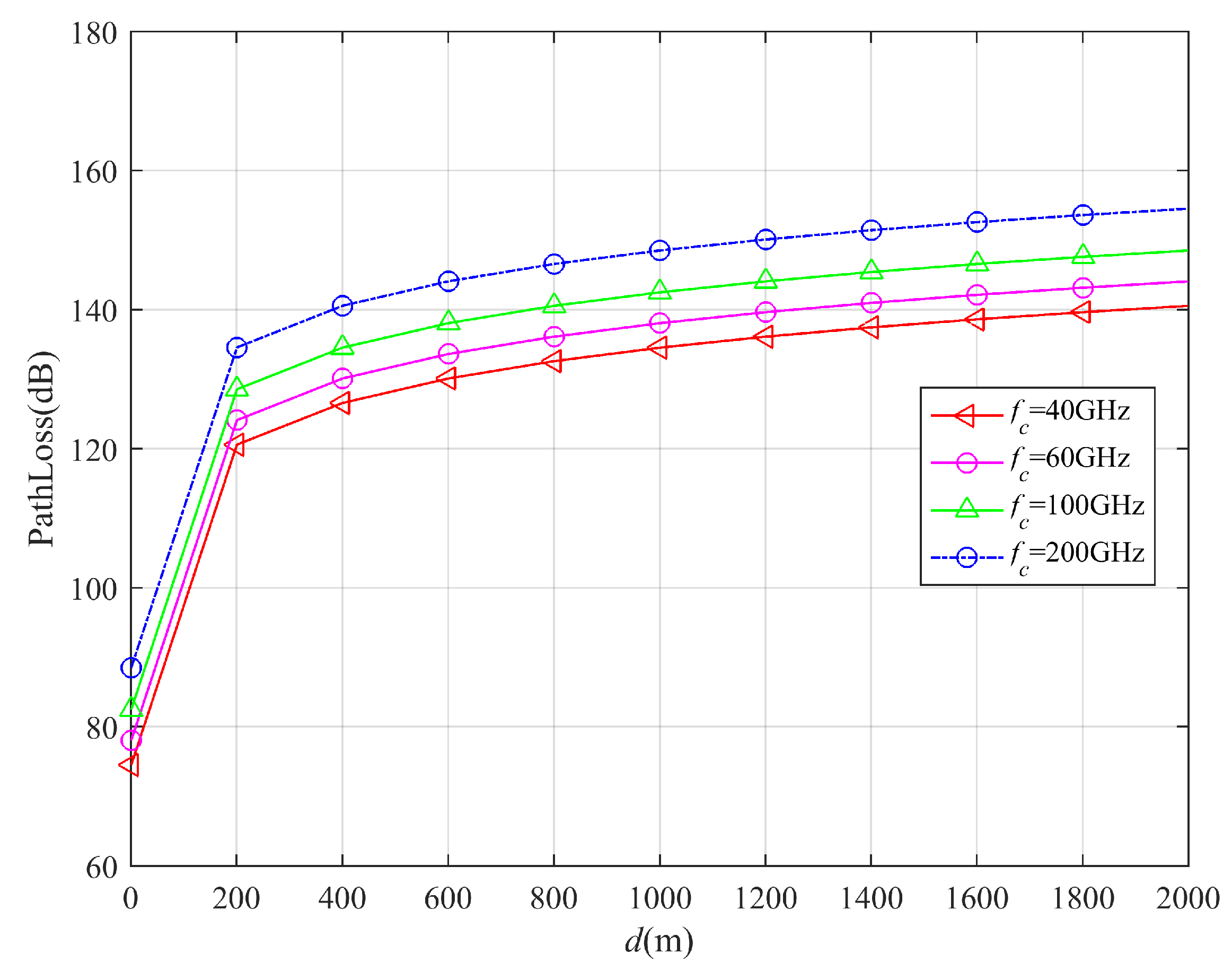
4.2.1. Path Loss Analysis

As shown in Figure 3, mmWave free space path loss shows significant dual dependence on transmission distance and frequency. The path loss increases with the transmission distance due to enhanced energy diffusion through reflection, refraction and scattering. In addition, the path loss also increases significantly with the carrier frequency f c increment. This relationship stems from fundamental wave propagation characteristics that shorter wavelengths at higher frequencies experience reduced obstacle penetration capability, causing greater signal energy to be reflected or absorbed. Therefore, these effects collectively degrade received signal power, resulting in increased path loss.

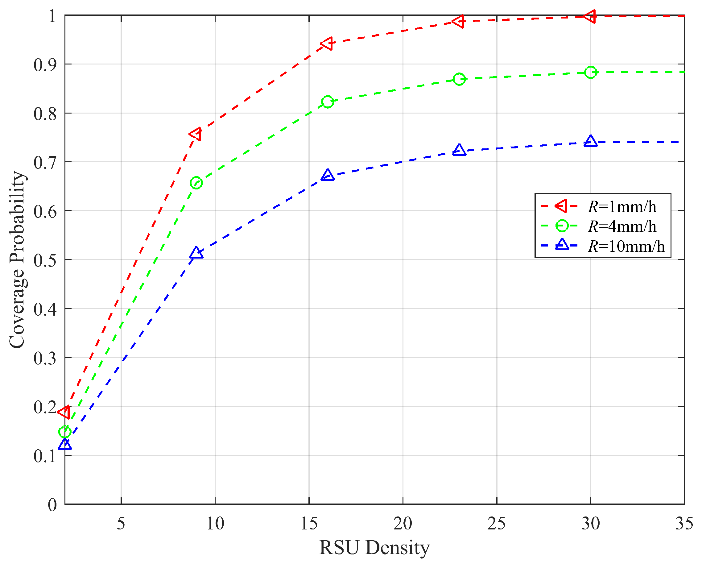
4.2.2. Coverage Analysis

(1)
Coverage Analysis in mmWave networks under different rainfall intensities.
As shown in Figure 4, RSU density has a strong positive correlation with network coverage in mmWave communication systems. Increasing the RSU density enhances the received signal power, effectively improving the coverage probability. It can also be seen from Figure 4 that the coverage performance decreases under heavier rainfall due to signal energy absorption and scattering by raindrops. When rainfall attenuation causes the received signal power to fall below the predefined threshold, coverage holes emerge, ultimately degrading the overall network performance.
Due to the inherent propagation characteristics of the mmWave frequency band, its signal coverage is limited by high-frequency path loss, and the effective coverage radius of a single mmWave RSU is limited. Through ultra-dense RSU deployment, the propagation distance between RSUs and VNs can be significantly shortened, reducing path loss while improving coverage efficiency.
(2)
Coverage Analysis in hybrid networks
In order to enhance mmWave communication reliability and reduce the rainfall attenuation effects, we simulate a hybrid microwave and mmWave network in the following.
The coverage probability evaluation proceeds as follows: we first calculate the SINR at a reference VN from its nearest mmWave RSU, and then compare this SINR with the predefined threshold γ t h . If the SINR > γ t h , the VN connects to the mmWave RSU; otherwise, it associates with a microwave RSU. The received SINR is then compared with the target SINR ( γ T ). If SINR > γ T , the VN is considered to be covered; otherwise, the VN is not covered. At last, derive the coverage probability from these comparisons.
The coverage probabilities for mmWave, microwave and the proposed hybrid networks are compared in Figure 5.
As shown in Figure 5, the coverage probability of the mmWave network shows a gradual improvement with increasing mmWave RSU density. However, the growth rate of the coverage probability begins to decelerate as the density further increases. In contrast, microwave networks demonstrate an initial increase in coverage probability with RSU density, followed by a subsequent stable state. Consequently, the coverage probability between the served microwave RSUs and the VN progressively decreases. The observed phenomenon can be attributed to the trade-off between signal enhancement and interference. When the RSU density is below approximately 20 RSUs/km, the increased density improves coverage. However, beyond this density value, interference becomes non-negligible and eventually dominates, causing the coverage probability to stabilize or grow at a diminished rate. Therefore, to maximize the coverage performance, we can first optimize the microwave RSU density for peak coverage probability and then maintain this value in the proposed hybrid network. By subsequently adjusting the mmWave RSU density, the hybrid network can achieve superior performance compared with pure microwave or mmWave deployments.

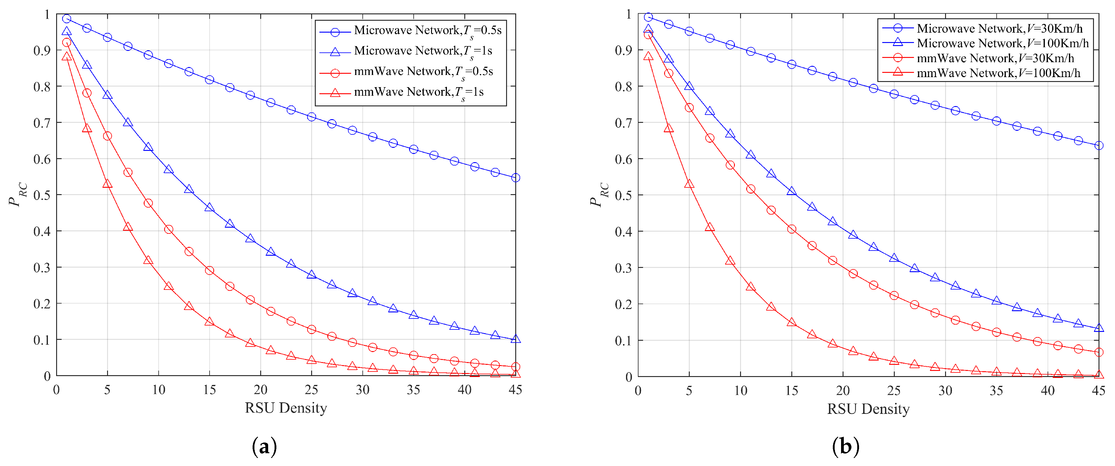
4.2.3. Connectivity Analysis

(1)
Connectivity Analysis in mmWave network
The connectivity between VN and the service RSU must be maintained throughout the entire time slot T S . The probability of remaining connected P R C analysis aims to determine the probability that the VN stays within the communication range of its serving RSU during T S , as shown in Figure 6.
From Figure 6, we observe that the P R C decreases as the RSU density increases. The reason for this can be explained as follows: with a higher network density, the distance between the VN and its serving RSU becomes shorter. Thus, a narrower beam projection region is formed, reducing the maximum distance before the VN moves out of its serving RSU’s communication range.
From Figure 6a, the P R C value for microwave networks is consistently higher than for mmWave networks. The difference arises because microwave beams offer a broader coverage than mmWave beams, making it more difficult for the reference VN to exit the serving RSU’s range within the given time slot. Additionally, the P R C increases occur within shorter time slots because the VN travels a shorter distance and moves out of the coverage area more slowly within the same time slot duration. Similarly, Figure 6b shows that P R C increases at lower speeds because the reference VN covers a shorter distance in the same time slot.
(2)
Connectivity Analysis for hybrid network
Figure 7 shows the connectivity probability for microwave, mmWave and the proposed hybrid vehicle networks with respect to the RSU density.
From Figure 7, the following key observations can be obtained. First, the hybrid vehicular network demonstrates superior connectivity probability compared with both the pure microwave and the pure mmWave vehicular networks, especially at lower RSU densities. However, this performance gap narrows as the RSU density increases. The reason is that the relative contribution of microwave RSUs diminishes with higher mmWave RSU densities. In such scenarios, microwave RSUs primarily serve as backup links when mmWave connections are unavailable due to blocking effects. The hybrid network combines both the advantages of mmWave and microwave networks, and thus shows better performance than both the pure microwave and pure mmWave vehicular networks.
Figure 7a shows the connectivity probability with RSU density at different vehicle speeds. The results show that slower-moving vehicles achieve higher connectivity probabilities than faster-moving vehicles. This difference arises because slower vehicles remain within coverage areas for longer durations within each time slot. Figure 7b depicts that shorter time slots lead to higher the connectivity probabilities due to more frequent beam alignment opportunities reduce the risk of connection failures. Figure 7c shows that the connectivity probability increases with main lobe beamwidth ψ M . Wider beams cover a broader coverage area, thus decreasing the probability of VNs losing connection with their serving RSUs. For microwave RSUs, ψ M is set to be 180° because these microwave RSUs are designed to provide coverage within a 180° beam angle in one direction.

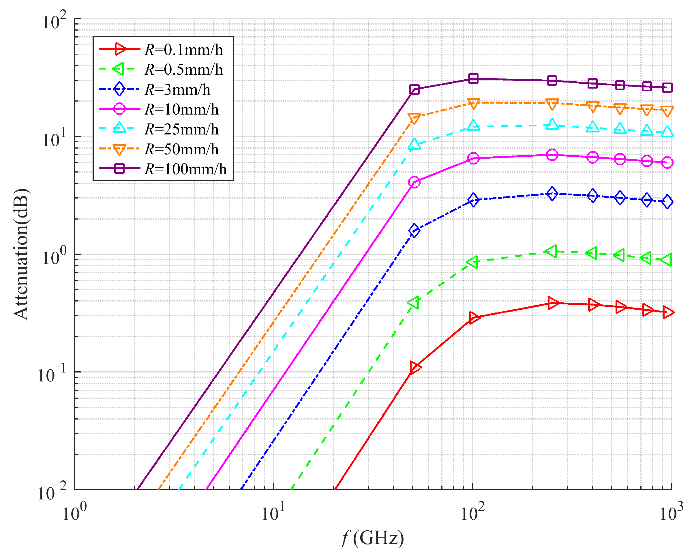
4.2.4. Rainfall Attenuation Analysis

Rainfall causes significant non-linear attenuation in mmWave signals, with the attenuation characteristics being dependent on signal frequency, transmission distance, and rainfall intensity. According to Equations (21)–(23), we calculate the related coefficients k and α , based on the real rainfall datasets from [34]. The rainfall attenuation related results are shown in Figure 8 and Figure 9.
(1)
Rainfall Attenuation Analysis with Different Rainfall Intensity
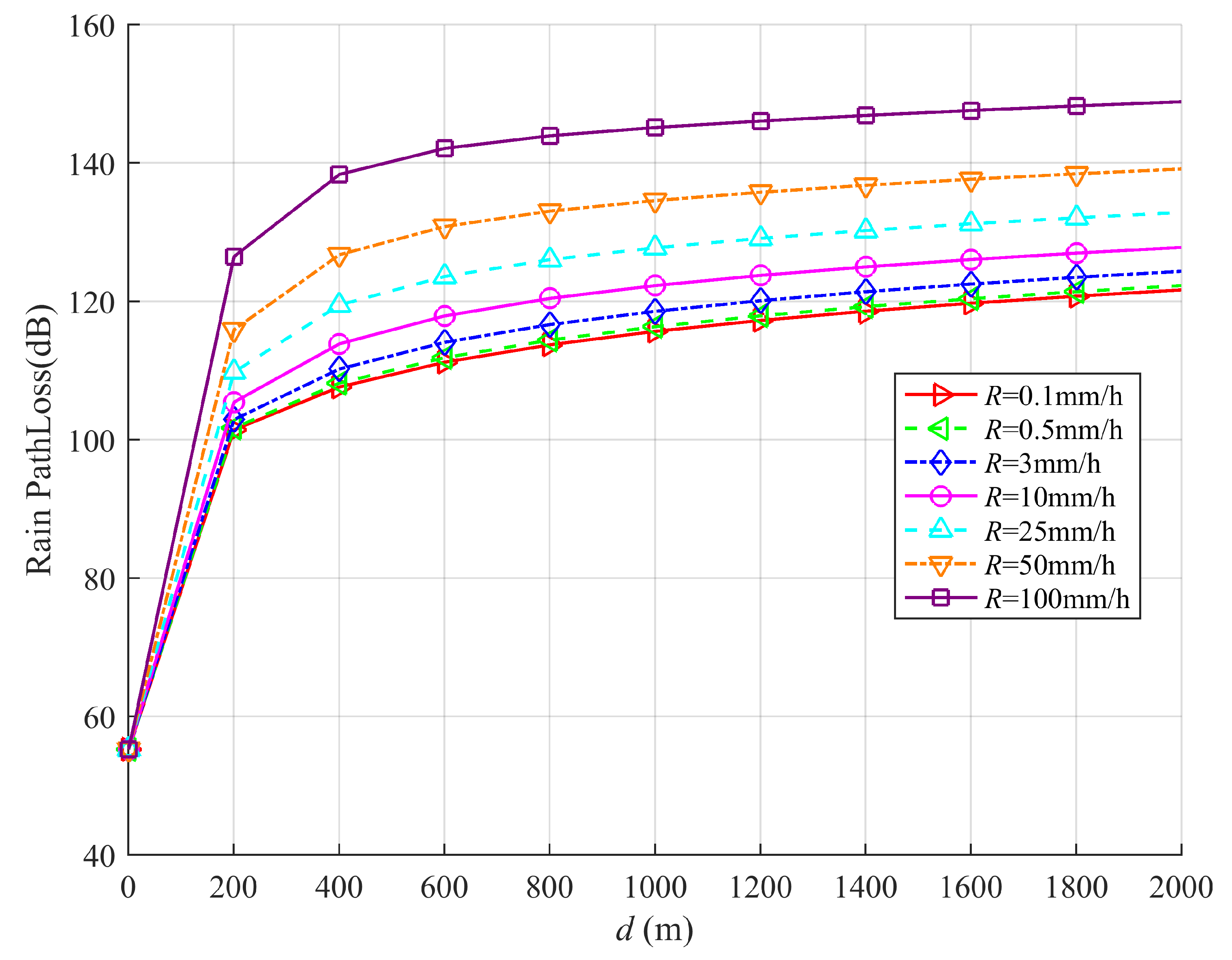
As shown in Figure 8, it can be seen that signal attenuation due to rainfall exhibits frequency-dependent characteristics. In lower frequency bands, rainfall-induced attenuation remains relatively weak. However, as frequency increases, the absorption loss becomes more pronounced, resulting in significantly stronger attenuation. This phenomenon occurs because higher frequencies induce greater dielectric loss in water molecules, converting electromagnetic energy into thermal energy. In addition, the effects get worse at higher rainfall intensity R. Higher rain intensity means more water drops in the air that can block or absorb the signal.
(2)
Rainfall’s effect on Path loss
As shown in Figure 9, the path loss characteristics of mmWave propagation in rain conditions show a significant path loss due to the cumulative effect of transmission distance and rainfall intensity. The results in Figure 9 show that when the propagation distance exceeds a certain threshold, such as d > 200 m, the rainfall attenuation causes nonlinear path loss growth, which is due to the cumulative effects of raindrop absorption and scattering along the transmission path. When the distance reaches about 800 m, the path loss curve tends to stabilize, indicating that the effects of rainfall attenuation tend to saturate after this critical distance. In addition, higher rainfall intensity leads to greater path loss at any given frequency. Specifically, light rain with smaller and sparser raindrops causes minimal loss, while heavy rain with dense and large raindrops causes stronger absorption and scattering, and leads to a significantly increasing path loss. This dual dependence property provides an important basis for designing rain loss compensation algorithms in mmWave communication systems.

5. Conclusions and Future Work

This paper proposes a hybrid mmWave-microwave network architecture to improve the coverage and connectivity performance of vehicular networks by symmetrically deploying mmWave RSUs and microwave RSUs on both sides of the road and ensuring communication between VN and RSUs. We analyzed the coverage and connectivity of mmWave, microwave and hybrid networks on highways, considering rainfall effects. Our evaluation analysis reveals that the hybrid network architecture achieves superior performance compared with pure microwave or mmWave networks in terms of both coverage and connectivity metrics.
In future work, we will conduct a comparative analysis with popular AI-based reliability algorithms, such as deep learning, to further demonstrate the superiority of hybrid networks in improving network reliability.

Author Contributions

Methods, J.S. (Jiaqing Sun); Software, J.S. (Jiaqing Sun) and J.W.; Investigation, C.L. and J.S. (Jiajun Shen); Writing—original draft, J.S. (Jiaqing Sun); Writing—review and editing, C.L.; Funding acquisition, J.S. (Jiajun Shen). All authors have read and agreed to the published version of the manuscript.

Funding

This work was funded by the Humanities and Social Science Fund of Ministry of Education [grant numbers 23YJAZH122]; the National Natural Science Foundation of China [grant numbers 62104208].

Data Availability Statement

All the results are simulated according to the algorithms. No data needed.

Conflicts of Interest

The authors declare no conflicts of interest.

Appendix A

Proof of Lemmas 1 and 2. 
The average coverage probability for a reference vehicular node(VN) served by microwave RSU is given by
P c o v , μ = W P γ μ > γ T f μ ( r μ ) d r μ = ( a ) W P P t g ^ 1 L 1 ( r μ ) σ μ 2 + I μ > γ T f μ ( r μ ) d r μ = W P g ^ 1 > γ T ( σ μ 2 + I μ ) P t L 1 ( r μ ) f μ ( r μ ) d r μ
where step (a) follows from (2) by substituting the expression of γ μ . Since g ^ 1 e x p ( 1 ) , the probability term inside (A1) can be written as
P g ^ 1 > γ T ( σ μ 2 + I μ ) P t L 1 ( r μ ) = exp γ T σ μ 2 P t L 1 ( r μ ) E I μ exp γ T I μ P t L 1 ( r μ ) = exp γ T σ μ 2 P t L 1 ( r μ ) L I μ ( γ T P t L 1 ( r μ ) )
where L I μ ( t ) is the Laplace transform of the random variable I μ evaluated at t and is given by
L I μ ( t ) = E I μ exp t I μ = E ξ μ , g ^ j exp t j ξ μ P t g ^ j L j ( r μ ) = E ξ μ j ξ μ E g ^ j exp t P t g ^ j L j ( r μ )
Since g ^ 1 e x p ( 1 ) , (A3) can be expressed as
L I μ ( t ) = E ξ μ j ξ μ 1 1 + t P t L j ( r μ ) = ( b ) exp 2 λ μ r μ ( 1 1 1 + t P t L j ( x ) d x ) = ( c ) exp 2 λ μ r μ ( t P t L j ( x ) 1 + t P t L j ( x ) d x )
Here, step (b) follows from the probability generating functional of 1−D P P P , while step (c) is obtained after some algebraic manipulation. Substituting t = γ T P t L 1 ( r μ ) in (A4), we obtain,
L I μ γ T P t L 1 ( r μ ) = exp 2 λ μ r μ γ T L j ( x ) L 1 ( r μ ) + γ T L j ( x ) d x = exp 2 λ μ F ( r μ , γ T )
where F ( r μ , γ T ) = r μ γ T L j ( x ) L 1 ( r μ ) + γ T L j ( x ) d x . Substitute (A5) in (A2), and then substitute the resulting expression in (A1), we obtain (9). Similarly, by replacing the beam gain and P D F for microwave, the mmWave coverage expression (8) can be obtained. □

Appendix B

Proof of Theorem 1. 
The average coverage probability contributed by mmWave RSU is given by,
P c o v , m , P S = W P [ γ m > γ T | γ m > γ t h ] P ( γ m > γ t h ) × f M ( r m ) d r m
Upon applying Bayes’ rule, (A6) can be rewritten as
P c o v , m , P S = W P γ m > γ T , γ m > γ t h f M ( r m ) d r m = W P γ m > m a x ( γ T , γ t h ) f M ( r m ) d r m = W P g 1 > m a x ( γ T , γ t h ) ( σ m 2 + I m ) P t G s L 1 ( r m ) f M ( r m ) d r m
Since g 1 e x p ( 1 ) , the simplification of (A7) follows the steps (A1)–(A5), just replace γ T with max ( γ T , γ t h ) . The final expression for P c o v , m , P S is given by
P c o v , m , P S = W exp max ( γ T , γ t h ) σ m 2 P t G s L 1 ( r m ) × exp 2 λ m H ( r m , γ T , γ t h ) f M ( r m ) d r m
where H ( r m , γ T , γ t h ) = r m max ( γ T , γ t h ) G I L j ( x ) G s L 1 ( r m ) + max ( γ T , γ t h ) G I L j ( x ) d x . □

Appendix C

Proof of Theorem 2. 
The coverage probability contributed by the microwave RSU is given by
P c o v , μ , P S = W { P γ μ , o p t > γ T | γ m < γ t h 1 P ( γ m > γ t h ) } f μ ( r μ ) d r μ
Upon applying Bayes’ rule and under the assumption of g 1 and g ^ 1 are i . i . d . , (A9) can be rewritten as
P c o v , μ , P S = W { P γ μ , o p t > γ T 1 P ( γ m > γ t h ) } f μ ( r μ ) d r μ
Here, the first term in (A10), i.e., P [ γ μ , o p t > γ T ] follows from Lemma 1 and (11), while the second term in (A10), i.e., P ( γ m > γ t h ) follows from Lemma 2. The final resulting expression is given by
P c o v , μ , P S = W exp γ T σ μ 2 P t L 1 ( r μ ) exp 2 λ μ , o p t F ( r μ , γ T ) f μ ( r μ ) d r μ × W 1 exp γ t h σ m 2 P t G s L 1 ( r m ) exp 2 λ m G ( r m , γ T ) f M ( r m ) d r m
The average coverage probability contributed by the microwave RSU in the hybrid vehicular network can be derived by averaging the resulting expression (A11) over its P D F , then (14) is obtained. □

References

  1. Kuutti, S.; Fallah, S.; Katsaros, K.; Dianati, M.; Mccullough, F.; Mouzakitis, A. A Survey of the State-of-the-Art Localization Techniques and Their Potentials for Autonomous Vehicle Applications. IEEE Internet Things J. 2018, 5, 829–846. [Google Scholar] [CrossRef]
  2. Lu, Z.; Qu, G.; Liu, Z. A Survey on Recent Advances in Vehicular Network Security, Trust, and Privacy. IEEE Trans. Intell. Transp. Syst. 2019, 20, 760–776. [Google Scholar] [CrossRef]
  3. Siegel, J.E.; Erb, D.C.; Sarma, S.E. A Survey of the Connected Vehicle Landscape—Architectures, Enabling Technologies, Applications, and Development Areas. IEEE Trans. Intell. Transp. Syst. 2018, 19, 2391–2406. [Google Scholar] [CrossRef]
  4. Sehla, K.; Nguyen, T.M.T.; Pujolle, G.; Velloso, P.B. Resource Allocation Modes in C-V2X: From LTE-V2X to 5G-V2X. IEEE Internet Things J. 2022, 9, 8291–8314. [Google Scholar] [CrossRef]
  5. Khan, B.S.; Jangsher, S.; Ahmed, A.; Al-Dweik, A. URLLC and eMBB in 5G Industrial IoT: A Survey. IEEE Open J. Commun. Soc. 2022, 3, 1134–1163. [Google Scholar] [CrossRef]
  6. Ghosh, A.; Maeder, A.; Baker, M.; Chandramouli, D. 5G Evolution: A View on 5G Cellular Technology Beyond 3GPP Release 15. IEEE Access 2019, 7, 127639–127651. [Google Scholar] [CrossRef]
  7. Chen, S.; Hu, J.; Shi, Y.; Zhao, L.; Li, W. A Vision of C-V2X: Technologies, Field Testing, and Challenges with Chinese Development. IEEE Internet Things J. 2020, 7, 3872–3881. [Google Scholar] [CrossRef]
  8. Rappaport, T.S.; Xing, Y.; Kanhere, O.; Ju, S.; Madanayake, A.; Mandal, S.; Alkhateeb, A.; Trichopoulos, G.C. Wireless Communications and Applications Above 100 GHz: Opportunities and Challenges for 6G and Beyond. IEEE Access 2020, 7, 78729–78757. [Google Scholar] [CrossRef]
  9. Chettri, L.; Bera, R. A Comprehensive Survey on Internet of Things (IoT) Toward 5G Wireless Systems. IEEE Internet Things J. 2020, 7, 16–32. [Google Scholar] [CrossRef]
  10. Ozpolat, M.; Kampert, E.; Jennings, P.A.; Higgins, M.D. A Grid-Based Coverage Analysis of Urban mmWave Vehicular Ad Hoc Networks. IEEE Commun. Lett. 2018, 22, 1692–1695. [Google Scholar] [CrossRef]
  11. Giordani, M.; Rebato, M.; Zanella, A.; Zorzi, M. Coverage and connectivity analysis of millimeter wave vehicular networks. Ad Hoc Netw. 2018, 80, 158–171. [Google Scholar] [CrossRef]
  12. Cheng, M.; Wang, J.-B.; Wu, Y.; Xia, X.-G.; Wong, K.-K.; Lin, M. Coverage Analysis for Millimeter Wave Cellular Networks With Imperfect Beam Alignment. IEEE Trans. Veh. Technol. 2018, 67, 8302–8314. [Google Scholar] [CrossRef]
  13. Nguyen, N.T.; Lee, K. Coverage and Cell-Edge Sum-Rate Analysis of mmWave Massive MIMO Systems With ORP Schemes and MMSE Receivers. IEEE Trans. Signal Process. 2018, 166, 5349–5363. [Google Scholar] [CrossRef]
  14. Chetlur, V.V.; Dhillon, H.S. Coverage and rate analysis of downlink cellular vehicle-to-everything (C-V2X) communication. IEEE Trans. Wirel. Commun. 2019, 19, 1738–1753. [Google Scholar] [CrossRef]
  15. Benelmir, R.; Bitam, S.; Fowler, S.; Mellouk, A. A novel mmwave beam alignment approach for beyond 5G autonomous vehicle networks. IEEE Trans. Veh. Technol. 2023, 73, 1597–1610. [Google Scholar] [CrossRef]
  16. Zaid, A.A.; Belmekki, B.E.Y.; Alouini, M.S. Aerial-aided mmWave VANETs using NOMA: Performance analysis, comparison, and insights. IEEE Trans. Veh. Technol. 2023, 73, 4742–4758. [Google Scholar] [CrossRef]
  17. Lin, T.; Cong, J.; Zhu, Y.; Zhang, J.; Ben Letaief, K. Hybrid Beamforming for Millimeter Wave Systems Using the MMSE Criterion. IEEE Trans. Commun. 2019, 67, 3693–3708. [Google Scholar]
  18. Zhao, D.; Lu, H.; Wang, Y.; Sun, H.; Gui, Y. Joint Power Allocation and User Association Optimization for IRS Assisted mmWave Systems. IEEE Trans. Wirel. Commun. 2022, 21, 577–590. [Google Scholar] [CrossRef]
  19. Liang, R.; Fan, J.; Liu, H.; Ge, Y.; Zhang, J. Dual-Hop Hybrid IRS-Aided Outdoor-to-Indoor mmWave Communications. IEEE Commun. Lett. 2022, 26, 2979–2983. [Google Scholar] [CrossRef]
  20. Zhang, H.; Chong, S.; Zhang, X.; Lin, N. A Deep Reinforcement Learning Based D2D Relay Selection and Power Level Allocation in mmWave Vehicular Networks. IEEE Commun. Lett. 2020, 9, 416–419. [Google Scholar] [CrossRef]
  21. Ju, Y.; Gao, Z.; Wang, H.; Liu, L.; Pei, Q.; Dong, M.; Mumtaz, S.; Leung, V.C. Energy-Efficient Cooperative Secure Communications in mmWave Vehicular Networks Using Deep Recurrent Reinforcement Learning. IEEE Trans. Intell. Transp. Syst. 2024, 25, 14460–14475. [Google Scholar] [CrossRef]
  22. Bahbahani, M.S.; Alsusa, E.; Hammadi, A. A directional TDMA protocol for high throughput URLLC in mmWave vehicular networks. IEEE Trans. Veh. Technol. 2022, 72, 3584–3599. [Google Scholar] [CrossRef]
  23. Yan, D.; Guan, K.; He, D.; Kim, J.; Chung, H.; Tian, D.; Zhong, Z. Blockage Effects of Road Bridge on mmWave Channels for Intelligent Autonomous Vehicles. IEEE Trans. Intell. Transp. Syst. 2024, 24, 2908–2919. [Google Scholar] [CrossRef]
  24. Sung, S.; Choi, W.; Kim, H.; Jung, J.-I. Deep Learning-Based Path Loss Prediction for Fifth-Generation New Radio Vehicle Communications. IEEE Access 2023, 11, 75295–75310. [Google Scholar] [CrossRef]
  25. Semiari, O.; Saad, W.; Bennis, M.; Debbah, M. Integrated millimeter wave and sub-6 GHz wireless networks: A roadmap for joint mobile broadband and ultra-reliable low-latency communications. IEEE Wirel. Commun. 2019, 26, 109–115. [Google Scholar] [CrossRef]
  26. Wang, F.; Wang, H.; Feng, H.; Xu, X. A Hybrid Communication Model of Millimeter Wave and Microwave in D2D Network. In Proceedings of the 2016 IEEE 83rd Vehicular Technology Conference (VTC Spring), Nanjing, China, 15–18 May 2016; pp. 1–5. [Google Scholar]
  27. Saluja, D.; Singh, R.; Saluja, N.; Kumar, S. Connectivity Improvement of Hybrid Millimeter Wave and Microwave Vehicular Networks. IEEE Trans. Intell. Transp. Syst. 2023, 24, 1456–1464. [Google Scholar] [CrossRef]
  28. Mehrpouyan, H.; Matthaiou, M.; Wang, R.; Karagiannidis, G.K.; Hua, Y. Hybrid millimeter-wave systems: A novel paradigm for hetnets. IEEE Commun. Mag. 2015, 53, 216–221. [Google Scholar]
  29. Shi, Y.; Alsusa, E.; Ebrahim, A.; Baidas, M.W. Uplink Performance Enhancement Through Adaptive Multi-Association and Decoupling in UHF-mmWave Hybrid Networks. IEEE Trans. Veh. Technol. 2019, 68, 9735–9746. [Google Scholar] [CrossRef]
  30. Arnau, J.; Atzeni, I.; Kountouris, M. Impact of LOS/NLOS propagation and path loss in ultra-dense cellular networks. In Proceedings of the 2016 IEEE International Conference on Communications (ICC), Kuala Lumpur, Malaysia, 22–27 May 2016; pp. 1–6. [Google Scholar]
  31. Atzeni, I.; Arnau, J.; Kountouris, M. Downlink Cellular Network Analysis With LOS/NLOS Propagation and Elevated Base Stations. IEEE Trans. Wirel. Commun. 2018, 17, 142–156. [Google Scholar] [CrossRef]
  32. Study on Channel Model for Frequencies from 0.5 to 100 GHz, Document TR 38.901 V14.0.0, 3rd Generation Partnership Project (3GPP). 2017. Available online: https://www.academia.edu/39972623/3_rd_Generation_Partnership_Project_Technical_Specification_Group_Radio_Access_Network_Study_on_channel_model_for_frequencies_from_0_5_to_100_GHz_Release_14 (accessed on 24 June 2025).
  33. Saluja, D.; Singh, R.; Saluja, N.; Kumar, S. Energy-Efficient Strategy for Improving Coverage and Rate Using Hybrid Vehicular Networks. IEEE Trans. Intell. Transp. Syst. 2022, 23, 430–443. [Google Scholar] [CrossRef]
  34. ITU-R P.838 Rainfall Data. Available online: https://www.itu.int/rec/R-REC-P.838 (accessed on 18 May 2025).
Figure 1. Highway system model (Two types of RSUs are symmetrically deployed on each road sides).
Symmetry 17 01054 g001
Figure 2. VNs remain in/out of the RSU’s coverage area, where Q = { m , μ } .
Symmetry 17 01054 g002
Figure 3. Free space path loss with distance d in mmWave networks.
Symmetry 17 01054 g003
Figure 4. Coverage probability with RSU density under mmWave networks.
Symmetry 17 01054 g004
Figure 5. Coverage probability with RSU density under mmWave, microwave and hybrid networks.
Symmetry 17 01054 g005
Figure 6. The probability that VN still in the communication range of RSUs duration T S under mmWave networks and microwave networks: (a) ψ M = 10 , V = 100 km / h , under different slot duration T S . (b) ψ M = 10 , T S = 1 s , under different VN speed V.
Symmetry 17 01054 g006
Figure 7. Connectivity probability with RSU density under mmWave, microwave and hybrid networks: (a) ψ M = 10 , T S = 1 s, under different VN speed V. (b) ψ M = 10 , V = 100 km/h under different slot duration T s . (c) T S = 1 s, V = 100 km/h, under different main lobe beamwidth ψ M .
Symmetry 17 01054 g007
Figure 8. Rainfall attenuation with frequency under different rainfall intensity R.
Symmetry 17 01054 g008
Figure 9. The rainfall’s effect on path loss with distance d under different rainfall intensity R.
Symmetry 17 01054 g009
Table 1. Symbols and meanings.
ParameterMeaning
r m , r μ Distance of reference VN from its serving mmWave and microwave RSU, respectively
ζ m Set of mmWave RSUs modeled by 1 − D P P P
ζ μ Set of microwave RSUs modeled by 1 − D P P P
λ m , λ μ Density of mmWave RSUs and microwave RSUs, respectively
λ T Density of mmWave plus microwave RSUs
QCharacterize the radio access technology (RAT) (i.e., Q = { m , μ } either mmWave (m) or microwave ( μ ))
c 0 Near field path loss at 1 − m distance
G I Antenna gain of mmWave interfering link
γ T , γ t h Target SINR and SINR threshold, respectively
S = { L ,   N L } Possible states of links: L denotes LOS link, and N L denotes NLOS link
P m L , P μ L LOS probability for mmWave and microwave link, respectively
γ m , γ μ SINR of reference VN associated with mmWave and microwave RSUs, respectively
h o ,   H U ,   λ O Height of obstacles, height of RSU, obstacle density, respectively
f m , f μ mmWave carrier frequency, microwave carrier frequency, respectively
B m , B μ mmWave bandwidth, microwave bandwidth, respectively
P t Transmit power of mmWave or microwave RSU
ψ M ,   G s ,   g s Beamwidth of main lobe, main lobe gain, side lobe gain of directional antenna pattern for mmWave RSU
T s ,   V Time slot duration, vehicle speed
σ m 2 ,   σ μ 2 Noise power added by mmWave and microwave RSU, respectively
α m , L ,   α m , N L Path loss exponent for LOS and NLOS link in mmWave RAT, respectively
α μ , L ,   α μ , N L Path loss exponent for LOS and NLOS link in microwave RAT, respectively
W ,   w Road width per direction, lane width
Nnumber of lanes per direction
L r o a d Road length
Table 2. System parameter setting.
ParameterValue
f m , f μ 28 GHz, 2 GHz
P t 30 dBm
ψ M 10
G s ,   g s 18 dBi, −2 dBi
T s {0.1, 0.5, 1} s
V{30, 60, 100} km/h
W ,   w 7.4 m, 3.7 m
L r o a d 10 km
N2 lanes per direction
h o ,   H U ,   λ O 1 m, 12 m, 1
N 0 −174 dBm/Hz
σ m 2 ,   σ μ 2 N 0 B m , N 0 B μ
B m ,   B μ 100 MHz, 10 MHz
α m , L ,   α m , N L 2, 4
α μ , L ,   α μ , N L 2.09, 3.75
γ T , γ t h 0 dB, −5 dB
Disclaimer/Publisher’s Note: The statements, opinions and data contained in all publications are solely those of the individual author(s) and contributor(s) and not of MDPI and/or the editor(s). MDPI and/or the editor(s) disclaim responsibility for any injury to people or property resulting from any ideas, methods, instructions or products referred to in the content.

