Article

Numerical Study of the Combustion-Flow-Thermo-Pyrolysis Process in an Innovative Externally Heated Oil Shale Retort

School of Metallurgy and Energy, Wuhan University of Science and Technology, No. 947 Heping Avenue, Qingshan District, Wuhan 430081, China
*
Author to whom correspondence should be addressed.
Symmetry 2025, 17(7), 1055; https://doi.org/10.3390/sym17071055
Submission received: 9 May 2025 / Revised: 17 June 2025 / Accepted: 1 July 2025 / Published: 3 July 2025
(This article belongs to the Section Engineering and Materials)

Abstract

A novel externally heated retort for Jimsar oil shale resources is proposed, and the symmetrical mathematical model of the transport process in the retort is established through intensively studying the mechanisms of shale gas flows, heat transfer, and pyrolysis reactions in the retort. The descriptions of axial and radial movements and temperature of oil shale and gases, and the distribution of pyrolysis reaction and yielding of gaseous products and semi-coke in various regions of the retort are simulated. The results show that oil shale can pyrolyze gradually from the region near the wall to the core region of the retorting chamber and pyrolyze completely at the bottom of the retorting zone through receiving the heat flux transferring from the combustion channels. The final pyrolysis temperature of oil shale is 821.05 K, and the outlet temperature of semi-coke cooled by cold recycled gas is 676.35 K, which are in agreement with the design requirements. In total, 75 toil shales can be retorted in one retorting chamber per day, and the productivity of the retort can be increased by increasing the number of retorting chambers. The fuel self-sufficiency rate of this externally heated oil shale retort can reach 82.83%.

1. Introduction

Oil shale, a fine-grained sedimentary rock containing significant amounts of kerogen which can be converted into shale oil and combustible gas through retorting process, is regarded as a valuable supplemental and alternative energy of conventional oil [1,2,3]. Therefore, several oil shale-retorting technologies have been designed and used in the past 100 years.
The commercially applied and widely recognized retorting technologies in recent years are mainly based on internally heating technology by introducing gas or solid heat carriers into the reactor [4,5]. The typical structure of the retorts based on gas heat carriers have the largest commercial amounts and have the advantage of being cheaper and simpler, such as the Fushun-type process, SJ (SanJiang) type process, gas full-circulation type process, Kiviter process, and Petrosix process. However, this retort type usually has a large volume of carrier gas, which will decrease the oil yield and increase the water consumption and equipment cost.
Solid heat carrier pyrolysis processes have usually higher shale oil yield, better adaptability for small-size oil shale, and smaller effluent gas volume that simplifies the shale oil recovery system [6,7,8], such as ATP (Alberta Taciuk Process), Enefit, and Petroter processes. However, the equipment is much more complicated and expensive. For example, the Fushun Mining Group Co. Ltd. (China) collaborated with UMATAC (Canada) and Polysius (Germany) and invested more than 100 million dollars to construct an 8.2 m diameter and 62.5 m long ATP pyrolysis process in 2005. Moreover, the ATP still did not reach the design requirements until 2024 [5]. Additionally, the solid heat carrier pyrolysis processes are confronted with significant challenges related to high dust entrainment in shale oil products. Li et al. [9] reported that more than 10 wt.% dust in shale oil seriously affects the oil quality and causes difficulty in downstream processing of the oil.
In fact, the earliest oil shale-retorting technologies that were implemented in industrial applications are mostly based on the external heating method from Estonia and Russia. The oil yield of tunnel ovens and Davidson rotary retorts could reach that of the Fischer assay [4]. Because of the substandard construction quality, inferior fabrication materials, and low automation proficiency in the 1930s, the tunnel ovens and Davidson rotary retort were characterized by frequent maintenance requirements and high repair demands, coupled with suboptimal thermal efficiency and short equipment service lives, which ultimately led to their operational discontinuation. Today, most of the disadvantages have been corrected, and the external heating method has been widely used in coking industry. Regenerative coke oven battery is widely used in the word and it contributes more than 90% of the total coke production [10], with the heating efficiency of above 82%.
The Jimsar oil shale mineralized belt, Xinjiang northwestern China, is abundant in oil shale resources but seriously short of water resources. Therefore, the external heating pyrolysis method with the advantages of low export gas volume, high oil yield and proven technique is being concerned again in recent years. Lin and Xu et al. [11,12] extended several indirectly heated fixed bed reactors with particularly designed internals to solve the problems of low shale oil yield and low heating efficiency to shale particles in conventional indirectly fixed beds. Fushun Mining Group Co., Ltd. (Fushun, China) and Jilin University (Changchun, China) developed an externally heated oil shale retort according to coking oven, and built a pilot plant with a processing capacity of 2.4 × 10⁴ kg/d and the assorted oil recovery system [13]. The continuous pilot plant test showed that the oil production rate of the retort was 93.18%, and the oil yield of the whole system was 83.55%, which was increased more than 10% comparing with that of the Fushun oil shale-retorting process. Xinjiang BaoMing Mines Co., Ltd. (Changji, China) also considers that the decrease in export gas volume can proportionally decrease the consumption of cooling water and the production of phenol contaminated wastewater in the oil recovering system, through the industrial production experience of gas full-circulation retort.
As described above, an externally heated retort with high heat efficiency and long equipment lifetimes could be an effective oil shale-retorting method. Hence, a novel externally heated retort is proposed according to coke oven and Jimsar oil shale pyrolysis characteristics, to utilize the oil shale resource of Jimsar oil shale mineralized belt. The present paper is devoted to introduce the innovative externally heated oil shale retort in detail, and to establish a symmetrical mathematical model of transport process in the retort for intensively studying the mechanisms of materials flows, heat transfer and pyrolysis reactions in the retort.

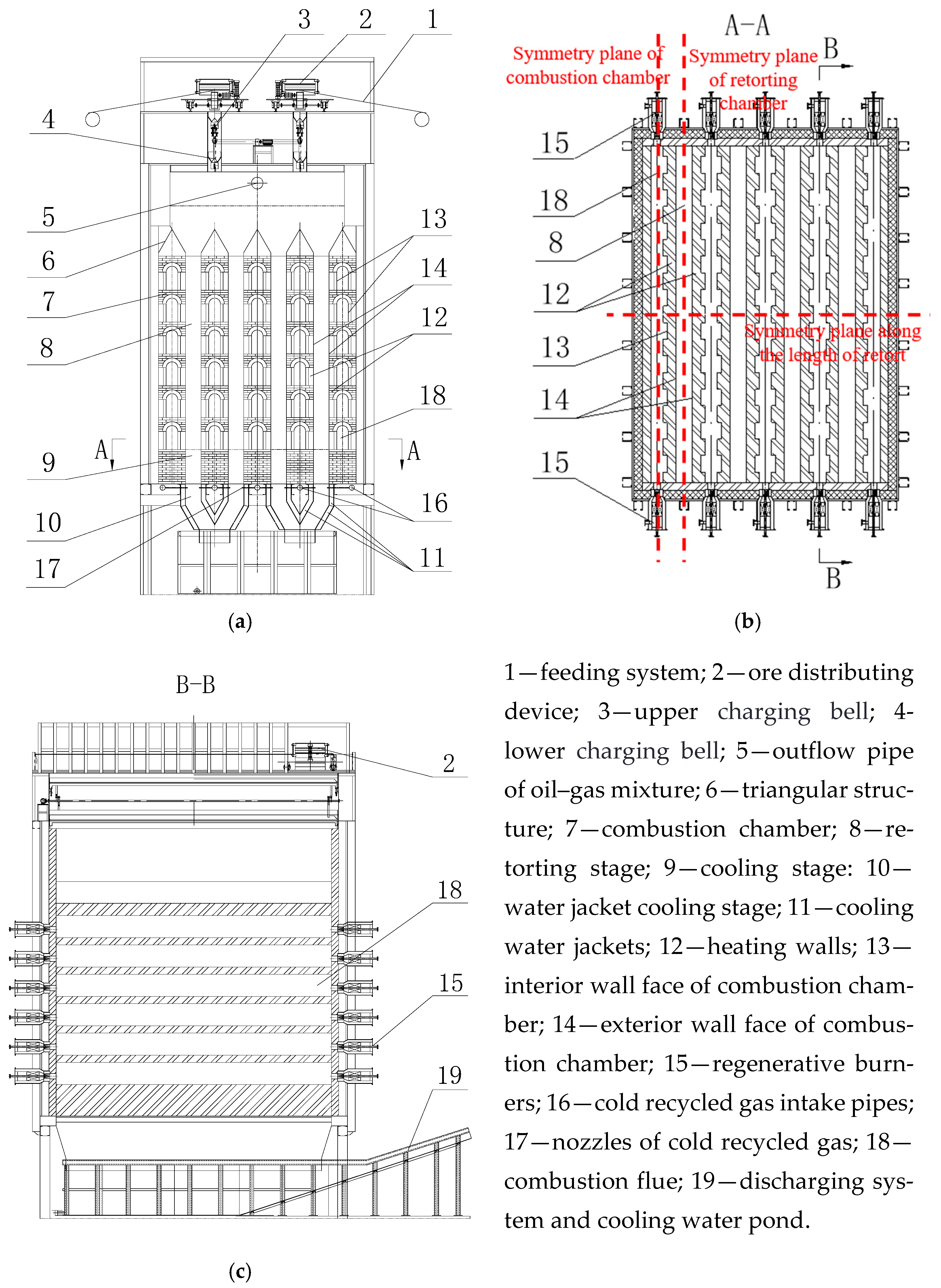
2. Structure of the Externally Heated Oil Shale Retort Battery

The main structure of the innovative externally heated oil shale retort with four retorting chambers proposed in this paper is shown in Figure 1. The retort consists of a number of symmetrically distributed retorting chambers that are heated by a set of combustion chambers through the heating walls. For large retort battery, the number of retorting chambers can be more than 50, and the productivity can be increased by increasing the number of retorting chambers and the layers of the combustion flues. In this paper, the oil shale retort with four symmetrically distributed retorting chambers is used in drawing design, material balance calculation, and heat balance calculation, and the daily treatment capacity is 3 × 10⁵ kg of oil shale in the size range of 6–50 × 10−3 m.
The combustion chamber is composed of multi-layer combustion flues arranged vertically from bottom to top. The retorting chamber surrounded by the heat conduction wall of two rows of adjacent combustion chambers is the main part of the oil shale pyrolysis. The interior heating wall of the combustion flues is built with composite brick as the battlement walls, which can not only increase the contacting area and residence time between the combustion exhaust gas and the heating walls to improve the thermal efficiency, but also ensure the strength and thermal conductivity of the heating walls.
A pair of regenerative ceramic burners are installed at both sides of each combustion flue of the combustion chamber. Through adjusting the working state of the burners in each layer of the combustion flue, the temperature of the interior wall face of combustion flues can be controlled between 1073.15 K and 1573.15 K, while the temperature of the exterior wall face of combustion chamber (i.e., the walls of the retorting chambers) can be controlled between 623.15 K and 923.15 K from top to bottom, to reduce the secondary pyrolysis of the retorting products in the upward-flowing process.
The top of the retorting chamber is the oil shale storage stage (preheating stage). The oil shale particles are fed into the storage stage and preheated by recycled gas and gaseous pyrolysis products. Thereafter, the oil shale particles are heated during their gradual and continuous downward flow, and are completely converted into semi-coke and the oil-gas mixture within the retorting stage. The cold recycled retorting gas injected from the bottom of the cooling stage cools the semi-coke and recovers the heat of the semi-coke during the upward-flowing process. Finally, the semi-coke is cooled to ambient temperature within a water-cooling pond and discharged out by the pusher mechanism, and the shale oil and gas are separated from the oil-gas mixture emanating from the retort top alongside recycled gas through three sequential processes: the cryogenic separator, electrostatic oil separator, and water scrubbing tower. The separated gas is fractionated into cold recycled gas directly routed to the retort bottom for recycling, and the burning gas that is supplied to the regenerative burners for heating the system.
The pyrolysis yields of gases and oil of Jimsar oil shale are 2.45% and 8.90% [14]. Additionally, the high net calorific value of pyrolysis gases is larger than 3.205 × 10⁷ J/m3. According to the calculation of material balance and heat balance [15], the fuel consumption of the retort with 4 retorting chambers is 310 Nm3/h, which means that the pyrolysis gas from the retorting process could supply 82.83% of the fuel consumption for the retort. Additionally, the thermal efficiency of the retort is larger than 68.4%.

3. Mathematical Model

Based on the dual-mesh method [16], a coupled mathematical model integrating gas–solid two-phase flow, heat transfer, and pyrolysis reaction was developed for the externally heated oil shale retort, enabling the numerical investigation of flow dynamics, thermal transport, and pyrolysis evolution within the reactor. The 3D model of the retort is built using SolidWorks 2022 and the grids of the model are generated using ICEM CFD. The height of the externally heated oil shale retort with four retorting chambers proposed in this paper is 12 m, including a 2.5 m preheating stage, 1.5 m storage stage, 4.1 m retorting stage, and 3.9 m cooling stage. According to the symmetry characteristics of the retort, 1/4 of a combustion chamber and a retorting chamber are taken as the research object. The symmetry planes are shown in Figure 1.
In order to improve simulation accuracy and efficiency, the simultaneous transport processes in the combustion flues and the retorting chambers were calculated severally through decoupling method [17] on the basis of the fluent. The grid quantity of the retorting chamber model is about 80 × 104, while that of the combustion flue model is 110 × 104. Grid independence of the retorting chamber model was verified using grid sizes of 50 × 104, 60 × 104, 70 × 104, 80 × 104 and 100 × 104, while that of the combustion flue model was validated with grid sizes of 80 × 104, 90 × 104, 100 × 104, 110 × 104 and 120 × 104. The results indicated that both models achieved numerical convergence when the grid size exceeded 70 × 104 and 90 × 104, respectively. The heat flux values on each interior wall faces of combustion flues are was approximated as constant, which can be calculated through heat balance calculation. Then the heat flux values are adopted as the boundary condition of the steady heat transfer with combustion in combustion flues, and the unsteady heat transfer with pyrolysis in retorting chambers. The grid partitions and the coupling boundary are shown in Figure 2. To simplify the mathematical formulation, the following assumptions are made: (1) Fragmentation of oil shale/semi-coke is neglected during the retorting process. (2) Oil shale exhibits continuous flow from the bottom of the 1.5 m storage stage, while cold recirculated gas is uniformly injected into the retort from the cooling stage bottom. (3) Heat transfer between oil shale and gas is assumed to be limited to convective heat transfer. (4) Physical and chemical properties of the oil-gas mixture are assumed to be identical to those of the recycled gas.

3.1. Governing Equations in the Combustion Flues

The general conservation equation describing the flowing, combustion, heat and mass transfer of gas combustion can be seen in reference [18,19]. In this work, the non-premixed combustion model and the P1 radiation heat transfer model of the fluent were used:
(1)
Non-premixed combustion model
ρ f ¯ t + x i ρ u i f ¯ = x i μ t σ t f ¯ x i + S s
S s = B ρ f f u e l f o x × e x p E / R T × ρ f f u e l , f o x , T d f f u e l d f o x d T
where f ¯   is the average of the mixed score, the unit is percent. S s is the mass source term, E is the reaction activation energy, B represents the volume of retort gas consumed per hour, R is the molar gas constant, the subscript fuel represents fuel, and ox represents oxygen.
(2)
Radiation heat transfer model
d ( I σ i ) d x i = ( a + σ s ) I ( r , s ) + a n 2 σ T 4 π + σ s 4 π 0 4 π   I ( r , s ) ϕ ( r , s ) d Ω
where I is the total radiation intensity, a is the absorption coefficient, σ s   is the scattering coefficient, r is the position vector, s   is the direction vector, S i is the component of s , n is the refraction coefficient, s is the scattering direction vector, σ is the Stefan–Boltzmann constant, σ = 5.672 × 10 8   W / ( m 2 K 4 ) , T is the thermodynamic temperature, Ω is the solid angle, ϕ is the phase function which represents the spatial distribution characteristics of inward scattering.
Additionally, the k-epsilon (2 eqn) model is used for the turbulent flowing of flue in the combustion channel.

3.2. Governing Equations in the Retorting Chambers

(1)
The governing equations of gases:
Continuity equations:
ε ρ g t + ε ρ g ν g = S m i x
where ρ o s is the density of recycled gas.
Momentum equations:
ε ρ g ν g t + ν g ν g = ε p + ε μ g 2 ν g S ¯
where the pressure is denoted by p, while the momentum source term for gas flow through the oil shale/semi-coke bed is represented by S ¯ .
S ¯ = μ a ν g + C 2 1 2 ρ u m a g ν g
where the viscous resistance coefficient 1/ a and inertial resistance coefficient C 2 for the oil shale bed were determined using the Ergun and Blake–Kozeny equations, respectively [20]:
1 a = 160 d p 2 1 ε 2 ε 3
C 2 = 1.61 d p ( 1 ε ) ε 3
Energy equations:
ε ρ c p g T g t + p c p ν g T g = ω ε λ g T g i   h i J i + τ ¯ ¯ v g + h ν T o s T g + Q p
where the effective heat capacity and thermal conductivity of the recycled gas are denoted by c p , g and λ g , respectively.
(2)
The governing equations of oil shale:
Continuity equations:
1 ε ρ o s t + 1 ε ρ o s ν o s = S m i x
where the porosity of the oil shale packed bed is denoted by ε , density of oil shale by ρ o s , superficial gas velocity by v o s , and formation rate of pyrolysis products by S m i x .
Momentum equations:
1 ε ρ o s ν o s t + ν o s ν o s = 1 ε μ o s 2 ν o s
where μ o s is the dynamic viscosity of oil shale particles. The laminar model is chosen for the laminar flowing of oil shale particles in the retorting chamber.
Energy equations:
1 ε ρ c p o s T s t + ρ c p o s ν o s T o s = 1 ε λ o s T o s + h ν T g T o s + Q r + Q r s + Q p + Q q
where T o s and T g denote the temperatures of oil shale and gas, respectively; the effective heat capacity and thermal conductivity of oil shale are denoted by c p , o s and λ o s , respectively; ε is the void fraction of the oil shale bed; Q p is the enthalpy of gaseous pyrolysis products; Q r s signifies the pyrolysis reaction heat released within the temperature range of 523.15–803.15 K; Q p accounts for the latent heat of surface moisture vaporization, incorporated via equivalent specific heat according to Jin et al. [21]; and Q r quantifies the radiative heat transfer among oil shale particles. The radiative heat transfer is defined using the Rosseland approximation as follows [22]:
Q r = q r = k r d T o s / d x = 16 σ n 2 T o s 3 / 3 β e d T o s / d x
where the Stefan–Boltzmann constant is denoted by σ , and the refractive index by n. k r can be considered as the irradiative conductivity [23], and the extinction coefficient of the oil shale packed bed is denoted by β e [24], expressed as:
β e = 3 ( 1 ε ) / d p
where the average particle diameter of the oil shale particle group is denoted by d p .
The volumetric convection heat transfer coefficient h v can be calculated from the following equation:
h v = h o s f α o s f
where the heat transfer coefficient between oil shale and recycled gas is denoted by h o s f , and the specific surface area by α o s f . Based on the literature [24,25,26], the expressions for h o s f and α o s f are given as follows:
h s f = 2.0 + 1.1 P r 1 / 3   R e 0.6 λ g d p
α o s f = 6 ( 1 ε ) / d p
where P r = c p u g / λ g is the Prandtl number of gas and R e = ε ρ g d p ν g / μ g is the Reynolds number of gas.
(3)
Oil shale pyrolysis model:
Oil shale pyrolysis reactions can be expressed as [16]:
d m d T = A m f β e x p E R T A R T 2 β E e x p E R T 1 + 2 ! E / R T + 3 ! E / R T 2 +
where the formation rate of pyrolysis products at temperature T is denoted by m T ; the total yield of pyrolysis products, by m f ; the pre-exponential factor, by A; the apparent activation energy, by E; the ideal gas constant, by R; the absolute temperature, by T; the heating time, by t; where β, α, w 0 , w T , and w f denote the heating rate of the pyrolysis process, conversion rate of oil shale, initial mass of oil shale, the oil shale mass at temperature T, and the oil shale mass after the pyrolysis reaction, respectively.

4. Results and Discussion

4.1. The Combustion Process in the Combustion Flues

According to heat balance calculation and numerical simulation, which is symmetric, the fuel consumption of six combustion flues from top to bottom was obtained, as shown in Table 1. According to the fuel consumption and the heat transfer area of the coupling wall between the combustion flues and the retorting chamber, the average heat fluxes of the six coupling walls were calculated as shown in Table 1.
By controlling the commutation time of the regenerative burners, which is usually 30–90 s, the temperature of the exhaust gas can be controlled within 573.15 K, which means that most of the heat of the exhaust gas can be recovered to the combustion flues through preheating air. Meanwhile, according to the law of energy conservation, the heat exchanged between the flues and retorting chamber increases with the increase in fuel consumption in flue. Therefore, the temperature in the combustion flues is basically the same, and the average temperature is about 1623.15 K, as shown in Figure 3, although the fuel consumption of each combustion flue is different.
Zhang et al. [17] and Lin et al. [27] discussed the feasibility of simulating the simultaneous combustion, fluid flow, heat, and mass transfer process of coke oven using the decoupling simulation method, and showed that the calculated temperature values are basically consistent with the measured values. Gamrat et al. [28] employed the identical decoupling simulation framework as this study to model the temperature field and combustion product concentration profiles within the coke oven combustion chamber, accompanied by an analysis of mitigation strategies for NOx reduction in the combustion effluents.
The combustion flues, which are symmetric to the retort designed in this paper, are horizontal combustion flues, which are different in terms of the vertical channel of the coke oven. The advantages are that the temperature of the heating wall at different heights can be controlled by controlling the fuel consumption of each combustion flue, and the thermal efficiency of the retort can be improved. In reference [13], Fushun Mining Group Co. Ltd. (Fushun, China) and Jilin University (Changchun, China) developed an externally heated oil shale retort using a vertical combustion channel according to a coking oven and built a pilot plant with a processing capacity of 2.4 × 10⁴ kg/d and an assorted oil recovery system. The operating data show that the temperature at the top of the oven is high and hard to be controlled, which reduces the thermal efficiency and increases the operative difficulty. In this paper, the retort is designed a storage stage at the top of the retorting chamber on the basis of a horizontal combustion channel structure, where the oil shale can be preheated and the temperature on the top can be controlled.

4.2. The Flowing, Heat Transfer, and Pyrolysis Processes in the Retorting Chamber

4.2.1. Flowing Characteristics

The velocity distribution of oil shale/semi-coke in the retorting chamber is shown in Figure 4a. Although the mass of oil shale decreases gradually with the pyrolysis reaction, the volume [29,30] of oil shale particles does not change, so the velocity of oil shale on the same vertical plane remains basically unchanged. On the same horizontal midplane, the velocity of oil shale/semi-coke near the heating wall is lower than that at the retorting chamber center, attributed to the viscous drag between the wall and particles. This velocity gradient demonstrates a gradual increase from the wall boundary toward the central flow domain. In the previous work of this paper [31], the velocity variation of particles in the moving-down process in gas full circulation retort was studied through physical simulation and EDEM numerical simulation method, and the results also illustrating that the tracing particles the layer of tracer particles gradually changed from horizontal to V-shaped in vertical vessels due to the friction between the particles and the walls during the descending process. Ying et al. [32] and Zhang et al. [33] also found the same phenomenon of particle flowing characteristics.
The velocity distribution of gases in the retorting chamber is shown in Figure 4b. Cold recycled gas is injected into the retort from the base of the cooling stage. Additionally, the velocity of gas in the cooling stage is constant and smaller. As the gaseous pyrolysis products generated at different heights in the retorting stage are flowing upward with the cold recycled gas, the upward gas flow velocity increases with the height of the retort and reaches to stable state at the top of the retorting chamber where the pyrolysis reactions haven’t started.

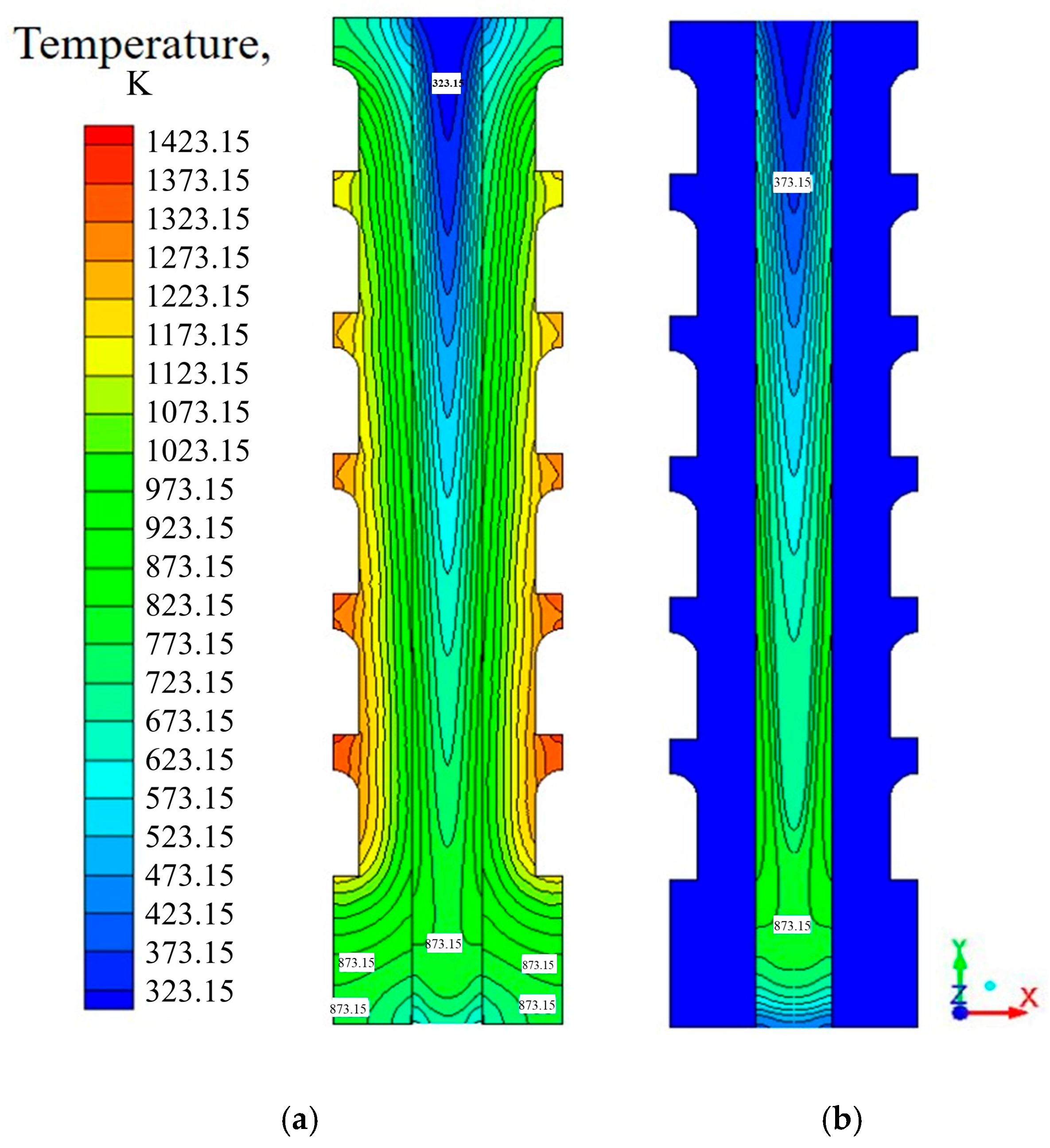
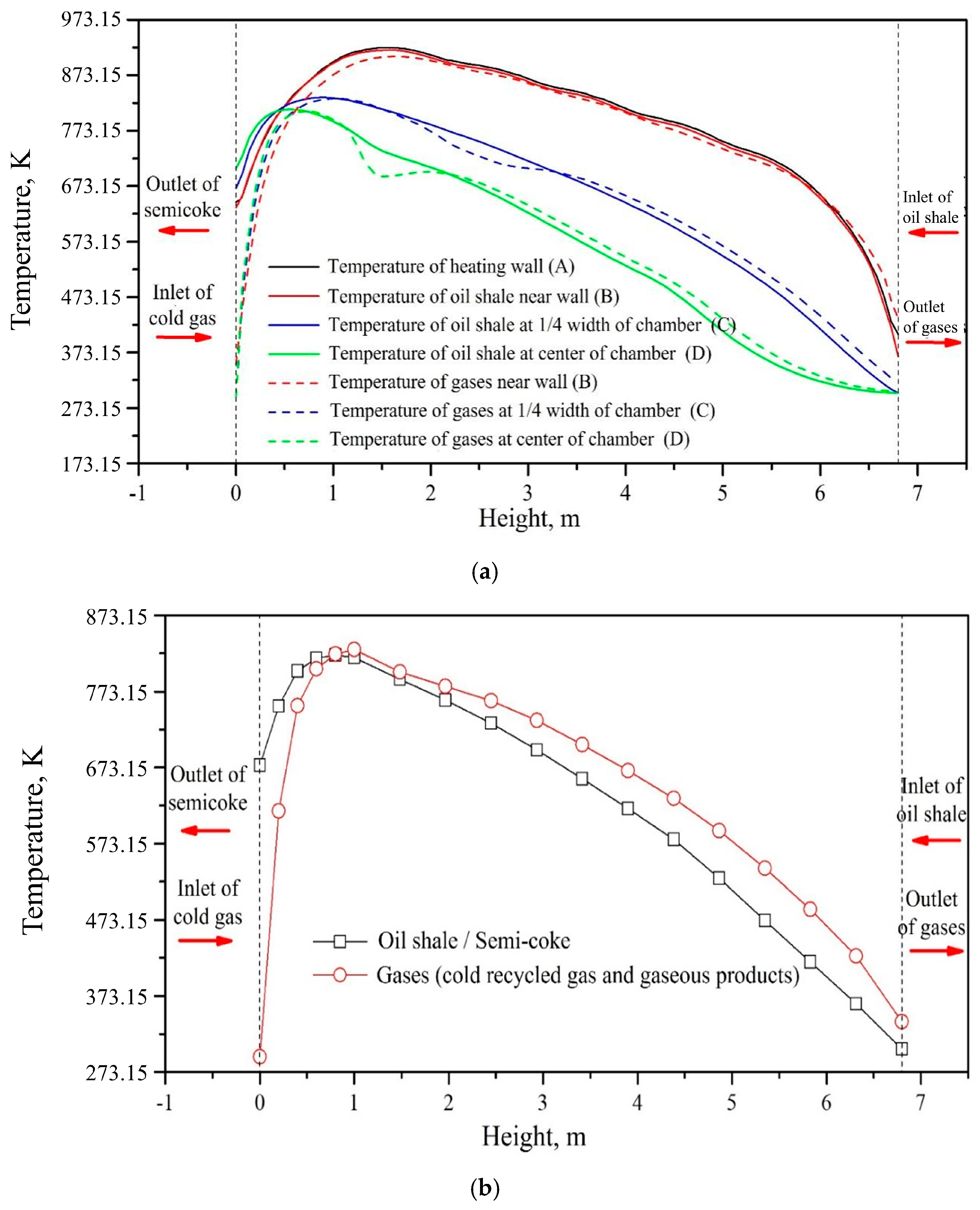
4.2.2. Temperature Distribution

The temperature nephogram in the retorting chamber is shown in Figure 5, and the temperature distribution curves along the height of the retort is shown in Figure 6. In the downward-moving process of oil shale particles in the retorting chamber, the heating walls continuously transfer the heat of exhaust gas from the combustion flues to the oil shale particles near the walls through radiation and conduction heat transfer. Then, the oil shale particles with higher temperature near the walls transfer the heat gradually to the oil shale in the center of the retorting chamber through the same combined heat transfer method. Hence, a gradual decrease in the temperature of gases and oil shale/spent shale is observed from the retort wall regions to the central regions in the horizontal direction, while the temperature of oil shale increases gradually during the moving down process in the retorting stage in the vertical direction.
Despite the temperature gradient of oil shale between the heating wall and chamber center exceeding 383.15 K (as illustrated in Figure 5), the vertically averaged mass-weighted temperature of the oil shale/semi-coke in the retorting chamber peaks at 821.05 K (as illustrated in Figure 6). This value aligns closely with the maximum temperature at the chamber center, attributed to the significantly higher flow velocity and mass flow rate of oil shale at the center compared to those near the heating walls. Hence, for the coke, the bondage and blockage of oil shale particles occurring in high retorting temperature could be avoided, and the yield of shale oil could be improved.
As the semi-coke move to the cooling stage, the semi-coke at the higher temperature transfers heat mainly through the heat convection method with the cold recycled gas blowing into the chamber from the bottom, cooling to 676.35 K before falling into the water jacket cooling stage and the cooling water pond. Also, it can be seen from Figure 6 that the semi-coke temperature near the heat wall is lower than that in the center of the retorting chamber in the cooling stage. The reason is that the temperature of the heating wall in the cooling stage is lower because there is no combustion flue at the bottom, and the mass flow rate of semi-coke near the wall is much lower than that in the center. Similarly, the temperature rising rate of the cold recycled gas at the center of the cooling stage is greater than that near the wall, as shown in Figure 6a.

4.2.3. Oil Shale Pyrolysis Reaction

The formation rate of gaseous pyrolysis products in the retorting chamber is illustrated in Figure 7. During the downward migration through the retorting chamber, the oil shale near the heating wall reaches the pyrolysis temperature and begins to convert into gaseous products and semi-cokes. As the heat from the combustion flues is transferred from the heating walls to the center of the retorting chamber, the oil shale nearby the center of the retorting chamber is pyrolyzed much later, the same as the temperature distribution. In the center of the retorting chamber, the oil shale starts to generate products while moving down to the fifth-row combustion flue from the top and pyrolyzes completely while moving down to the base of the retorting stage.
In addition, the formation rate of gaseous pyrolysis products near the heating wall is much lower than that near the center of the retorting chamber, due to the small velocity and mass flow rate of oil shale near the heating walls. Additionally, the formation rate of gaseous pyrolysis products is relatively small in the initial and completion stages of pyrolysis process, due to the pyrolysis reaction is mainly concentrated at 723.15–773.15 K.
The yield of pyrolysis products is shown in Table 2. For each of the retorting chambers shown in Figure 1, 75 × 103 kg oil shale could be retorted, and 64.7 × 10³ kg semi-coke and 10.3 × 10³ kg gaseous products could be produced per day. The theoretical oil and gas yield could reach the 100% of the Fischer oil yield of oil shale.

5. Conclusions

In this work, a novel externally heated retort for Jimsar oil shale resources is proposed, and a mathematical model for the transport process in the externally heated retort are established through intensively studying the mechanisms of shale gas flows, heat transfer, and pyrolysis reactions in the retort. The main conclusions are as follows:
(1)
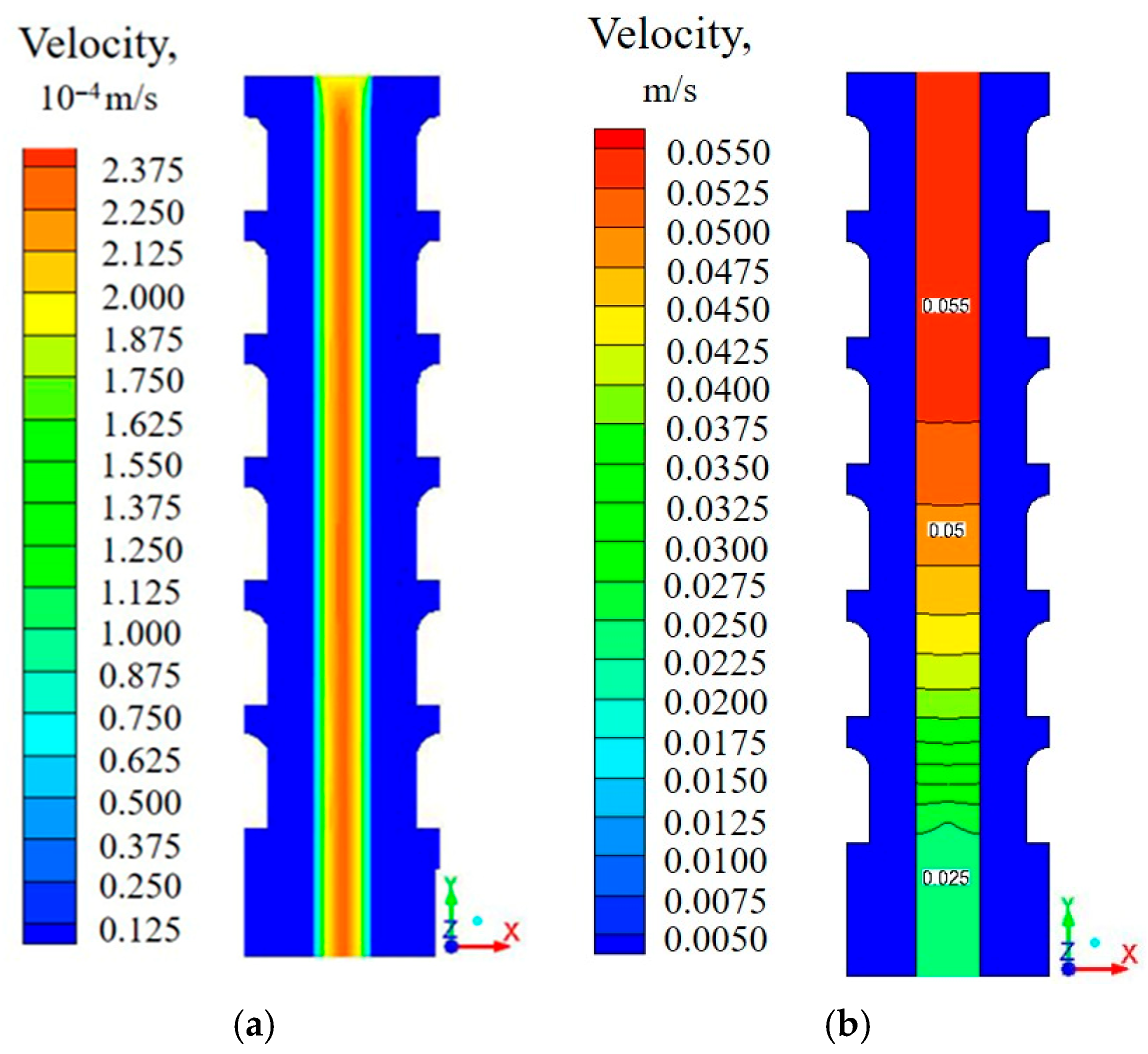
Horizontally, the velocity of oil shale particles demonstrates a gradual increase from the retort wall regions to the central regions, attributed to the viscous drag between particles and the wall. The velocity of gases has a similar pattern to that of oil shale.
(2)
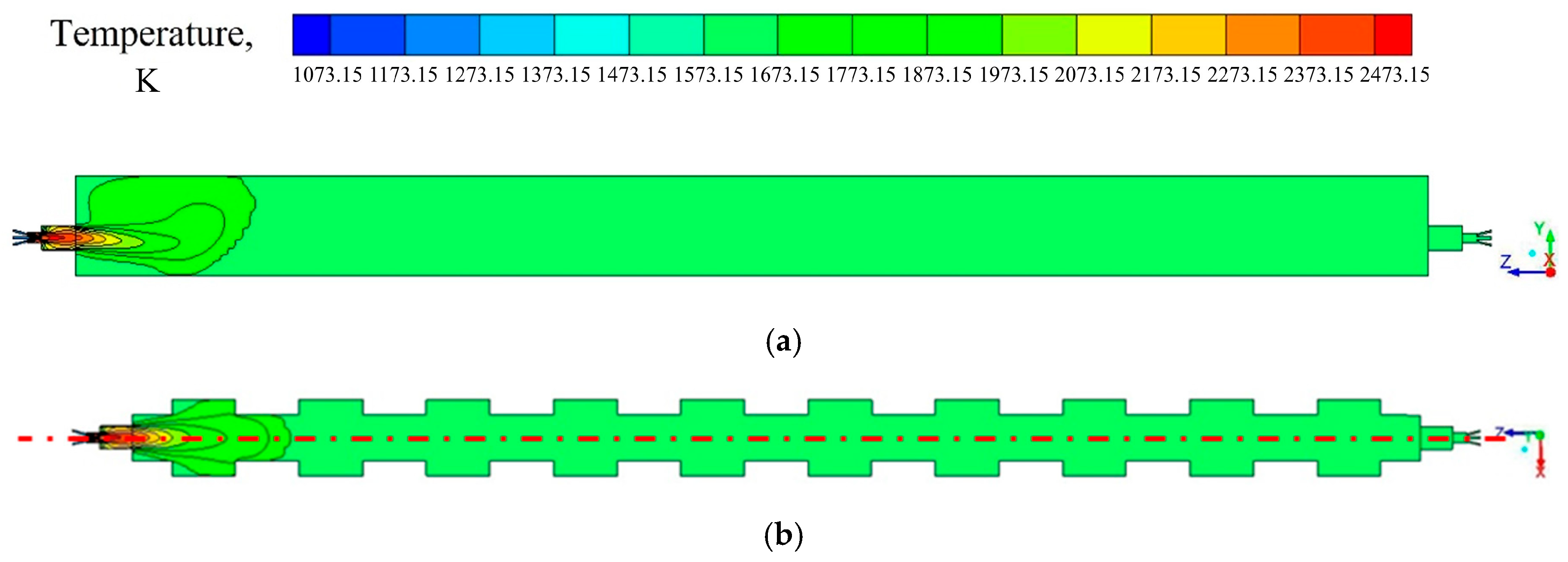
The temperature distribution in the combustion flues of the externally heated oil shale retort furnace is relatively uniform. Additionally, the flue gas temperature is about 1623.15 K. The fuel self-sufficiency rate of this externally heated oil shale retort can reach 82.83%.
(3)
The oil shales pyrolyze gradually from the region near the wall to the core region of the retorting chamber and pyrolyze completely at the bottom of the retorting zone. The final mass-weighted average pyrolysis temperature of oil shale is 821.05 K, and the outlet temperature of semi-coke cooled by cold recycled gas is 676.35 K, which are in agreement with the design requirements.
(4)
The gaseous products are mainly generated during their downward movement to the bottom of the retorting stage. The theoretical oil and gas yield could reach 100% of the Fischer oil yield of oil shale.

Author Contributions

Conceptualization, L.P.; validation, Y.M.; investigation, L.Z. and L.P.; data curation, L.P.; writing—original draft, L.Z. and L.P.; writing—review and editing, L.P. All authors have read and agreed to the published version of the manuscript.

Funding

This research was funded by National Natural Science Foundation of China, grant number 51904209.

Data Availability Statement

The original contributions presented in this study are included in the article. Further inquiries can be directed to the corresponding author.

Conflicts of Interest

The authors declare that they have no known competing financial interests or personal relationships that could have appeared to influence the work reported in this paper.

References

  1. Chen, Z.; Tian, Y.; Lai, D.; Zhan, J.-H.; Han, Z.; Xu, G.; Gao, S. Oil shale pyrolysis in a moving bed with internals enhanced by rapid preheating in a heated drop tube. Energy Convers. Manag. 2020, 224, 113358. [Google Scholar] [CrossRef]
  2. Lai, D.; Zhang, G.; Xu, G. Characterization of oil shale pyrolysis by solid heat carrier in moving bed with internals. Fuel Process. Technol. 2017, 158, 191–198. [Google Scholar] [CrossRef]
  3. Yang, S.; Wang, H.; Zheng, J.; Pan, Y.; Ji, C. Comprehensive review: Study on heating rate characteristics and coupling simulation of oil shale pyrolysis. J. Anal. Appl. Pyrolysis 2024, 177, 106289. [Google Scholar] [CrossRef]
  4. Qian, J.; Li, S.; Guo, S.; Ding, F. Oil Shale Distillation and Refining Technology; China Petrochemical Press: Beijing, China, 2014. (In Chinese) [Google Scholar]
  5. Ma, Y.; Xiang, Q.; Ding, K. Development of oil shale at home and abroad. World Pet. Ind. 2024, 31, 16–25. (In Chinese) [Google Scholar]
  6. Lai, D.; Chen, Z.; Shi, Y.; Lin, L.; Zhan, J.; Gao, S.; Xu, G. Pyrolysis of oil shale by solid heat carrier in an innovative moving bed with internals. Fuel 2015, 159, 943–951. [Google Scholar] [CrossRef]
  7. Yang, Q.; Qian, Y.; Kraslawski, A.; Zhou, H.; Yang, S. Advanced exergy analysis of an oil shale retorting process. Appl. Energy 2016, 165, 405–415. [Google Scholar] [CrossRef]
  8. He, J.; Wang, Q. Development and application of Estonia Galoter technology. J. Northeast. Dianli Univ. 2016, 36, 76–80. (In Chinese) [Google Scholar]
  9. Li, W.; Deng, J.; Yu, C. Development of lignite pyrolysis with solid heat carrier. Coal Chem. Ind. 2012, 158, 1–5. (In Chinese) [Google Scholar]
  10. Templado, J.L.; Ribas, J.; Lopera, J.M.; Rodríguez, H.d.A.; Lopez, J.J.F. Capacitive Charge-Level Measurement System for Coke Ovens. IEEE Trans. Ind. Appl. 2023, 59, 7839–7847. [Google Scholar] [CrossRef]
  11. Lin, L.; Zhang, C.; Li, H.; Lai, D.; Xu, G. Pyrolysis in indirectly heated fixed bed with internals: The first application to oil shale. Fuel Process. Technol. 2015, 138, 147–155. [Google Scholar] [CrossRef]
  12. Lin, L.; Lai, D.; Guo, E.; Zhang, C.; Xu, G. Oil shale pyrolysis in indirectly heated fixed bed with metallic plates of heating enhancement. Fuel 2016, 163, 48–55. [Google Scholar] [CrossRef]
  13. Xu, H. Semi-Industrial Experimental Study on Externally Heated Dry Distillation of Oil Shale. Master’s Thesis, Jilin University, Changchun, China, 2012. (In Chinese). [Google Scholar]
  14. Lu, H.; Pan, L.; Guo, Y.; Xiong, Q.; Dai, F.; Wang, S. Experimental investigation of the characteristics and transformation mechanism of Jimsar oil shale and derived shale oil. Processes 2023, 11, 411. [Google Scholar] [CrossRef]
  15. Da Silva, B.P.; Saccol, F.; Pedrazzi, C.; Caetano, N.R. Technical and Economic Viability for the Briquettes Manufacture. Defect Diffus. Forum 2017, 380, 218–226. [Google Scholar] [CrossRef]
  16. Pan, L.; Lu, H.; Dai, F.; Pei, S.; Wu, Q.; Huang, J. Numerical study of the flow, heat transfer and pyrolysis process in the gas full circulation oil shale retort. Oil Shale 2021, 38, 317–337. [Google Scholar] [CrossRef]
  17. Zhang, A.Q.; Feng, Y.H.; Zhang, X.X.; Wang, M.D.; Yang, J.F.; Xu, Y. Decoupling simulation of thermal processes in coupled combustion andcoking chambers of a coke oven. ISIJ Int. 2013, 53, 995–1001. [Google Scholar] [CrossRef]
  18. He, J.; Yang, X.; Li, X.; Cao, W.; Xu, H.; Yin, Q.; Jiang, X.; Liu, B. Comparative study on the molecular evolution of changqing petroleum coke during air and pure oxygen combustion: A ReaxFF method analysis. J. Clean. Prod. 2024, 452, 142104. [Google Scholar] [CrossRef]
  19. Smolka, J.; Slupik, L.; Fic, A.; Nowak, A.J.; Kosyrczyk, L. 3-D coupled CFD model of a periodic operation of a heating flue and coke ovens in a coke oven battery. Fuel 2016, 165, 94–104. [Google Scholar] [CrossRef]
  20. Pan, L.; Dai, F.; Tian, Y.; Zhang, F. Experimental investigation of the sphericity of irregularly shaped oil shale particle groups. Adv. Powder Technol. 2015, 26, 66–72. [Google Scholar] [CrossRef]
  21. Jin, K.; Feng, Y.; Zhang, X.; Wang, M.; Yang, J.; Ma, X. Simulation of transport phenomena in coke oven with staging combustion. Appl. Therm. Eng. 2013, 58, 354–362. [Google Scholar] [CrossRef]
  22. Modest, M. Radiative Heat Transfer, 2nd ed.; Academic Press: San Diego, CA, USA, 2003. [Google Scholar]
  23. Alazmi, B.; Vafai, K. Analysis of variants within the porous media transport models. J. Heat Transf. 2000, 122, 303–312. [Google Scholar] [CrossRef]
  24. Wang, F.; Shuai, Y.; Tan, H.; Zhang, X.; Mao, Q. Heat transfer analyses of porous media receiver with multi-dish collector by coupling MCRT and FVM method. Sol. Energy 2013, 93, 158–168. [Google Scholar] [CrossRef]
  25. Wang, F.; Shuai, Y.; Wang, Z.; Leng, Y.; Tan, H. Thermal and chemical reaction performance analyses of steam methane reforming in porous media solar thermochemical reactor. Int. J. Hydrogen Energy 2014, 39, 718–730. [Google Scholar] [CrossRef]
  26. Jiang, P.X.; Ren, Z.P.; Wang, B.X. Numerical simulation of forced convection heat transfer in porous plate channels using thermal equilibrium and nonthermal equilibrium models. Numer. Heat Transf. Part A Appl. 1999, 35, 99–113. [Google Scholar] [CrossRef]
  27. Lin, W.; Feng, Y.; Zhang, X. Numerical study of volatiles production, fluid flow and heat transfer in coke ovens. Appl. Therm. Eng. 2015, 81, 353–358. [Google Scholar] [CrossRef]
  28. Gamrat, S.; Poraj, J.; Bodys, J.; Smolka, J.; Adamczyk, W. Influence of external flue gas recirculation on gas combustion in a coke oven heating system. Fuel Process. Technol. 2016, 152, 430–437. [Google Scholar] [CrossRef]
  29. Xiong, Q.; Lu, H.; Pan, L.; Dai, F.; Wang, S. Characteristics of Shichanggou oil shale and its pyrolysis semi coke. Sci. Technol. Eng. 2023, 23, 8650–8659. (In Chinese) [Google Scholar]
  30. Yuan, Q.; Pan, L.; Lu, H.; Guo, Y.; Dai, F.; Wang, S. Physical characteristics of combustion ash in Shichanggou oil shale. Sci. Technol. Eng. 2023, 23, 8201–8211. (In Chinese) [Google Scholar]
  31. Lu, H.; Pan, L.; Guo, Y.; Zhou, S.; Xiong, Q.; Dai, F.; Pei, S.; Huang, J. Simulation investigation of the particle flow behavior in the gas full circulation oil shale retort. J. Pet. Sci. Eng. 2022, 215, 110674. [Google Scholar] [CrossRef]
  32. Ying, W.F. Mathematical & Physical Simulation of COREX Pre-Reduction Shaft Furnace. Ph.D. Thesis, Northeastern University, Shengyang, China, 2013. (In Chinese). [Google Scholar]
  33. Zhang, X.S.; Zou, Z.S.; Luo, Z.G. Influence of CGD structure on burden descending behavior in COREX shaft furnace. Metall. Res. Technol. 2019, 116, 304. [Google Scholar] [CrossRef]
Figure 1. The structure of the externally heated oil shale retort. (a) main view, (b) cross-sectional view A-A, (c) cross-sectional view B-B.
Symmetry 17 01055 g001
Figure 2. The grid partitions and the coupling boundary of retorting chamber (a, b), combustion flue (c) and the burner (d).
Symmetry 17 01055 g002
Figure 3. Simulation results of temperature distribution in combustion channel. (a) Longitudinal section; (b) cross-section.
Symmetry 17 01055 g003
Figure 4. The velocity distribution of oil shale/semi-coke (a) and gases (b) in the retorting chamber.
Symmetry 17 01055 g004
Figure 5. The temperature distribution of heating wall and oil shale/semi-coke (a) and gases (b) in the retorting chamber.
Symmetry 17 01055 g005
Figure 6. The average temperature profile of oil shale/spent shale and gases distributes vertically along the retort height: (a) at different width direction; (b) mass-weighted average temperature.
Symmetry 17 01055 g006
Figure 7. The formation rate of gaseous products in the retorting chamber.
Symmetry 17 01055 g007
Table 1. Fuel consumption in combustion flues and heat flux distribution of heat conduction wall.
Number of Layers
(from Top to Bottom)
123456
Fuel (m3/h)12.0012.5013.0013.0013.5013.50
Air (m3/h)99.60103.75107.90107.90112.05112.05
Heat flux of heating wall (103 W/m2)3.173.303.433.433.563.56
Table 2. The yield of one retorting chamber.
Oil Shale Treating Capacity (103 kg/d)Yield of Semi-Coke (103 kg/d)Yield of Gaseous Products (103 kg/d)
7564.710.3
Disclaimer/Publisher’s Note: The statements, opinions and data contained in all publications are solely those of the individual author(s) and contributor(s) and not of MDPI and/or the editor(s). MDPI and/or the editor(s) disclaim responsibility for any injury to people or property resulting from any ideas, methods, instructions or products referred to in the content.

