Article

Plume Characterization of Electrodeless Plasma Thruster with Configurable Exhaust

by
Artur A. Andronov
1,2,
Andrei I. Shumeiko
1,2,*,
Aslan D. Pashaev
2,
Petr A. Tsygankov
3,
Sergei V. Kovalev
1 and
Victor D. Telekh
1
1
Plasma Power Plants Department, Bauman Moscow State Technical University, 5/1 2-ya Baumanskaya Street, 105005 Moscow, Russia
2
R&D Department, Advanced Propulsion Systems LLC, 7 2/35/5 Nobel Street, 121205 Moscow, Russia
3
Department of Physics, Industrial University of Santander, Cl. 9 #27, Bucaramanga 680003, Santander, Colombia
*
Author to whom correspondence should be addressed.
Symmetry 2025, 17(5), 661; https://doi.org/10.3390/sym17050661 (registering DOI)
Submission received: 19 March 2025 / Revised: 18 April 2025 / Accepted: 24 April 2025 / Published: 26 April 2025

Abstract

:
Currently, there is a need for dynamic space missions based on small satellites. These missions can be supported by propulsion systems with thrust-vectoring capabilities. This capability can be realized based on electrodeless plasma thrusters (EPTs). EPTs stand out for their versatility, offering adjustable thrust characteristics and fewer components, making them ideal for small satellites. However, their efficiency remains below optimal levels, largely due to complexities in plasma acceleration. This research aims to better understand dominant acceleration mechanisms in EPTs by studying ion energy distribution function changes based on exhaust orifice diameter and power variations. The total power supplied to the thruster varies in the range of 24 to 40 W, and the exhaust diameter varies in the range from 6.5 to 10.5 mm. It was found that the ion velocity does not change as a function of the diameter of the exit aperture. This indicates the insignificance of the mechanism of the gas-dynamic acceleration of plasma in EPTs with a small form factor and supports recent views that the main contribution to the acceleration of particles in EPT is made by electromagnetic effects. The findings could help refine EPT designs, enhancing their overall effectiveness and reliability for future space missions.

1. Introduction

The use of space propulsion systems (PSs) has become imperative for a wide spectrum of commercial and scientific space undertakings [1]. Initially, PSs primarily served booster roles, including shifting satellites from parking into target orbits [2]. Yet, the burgeoning enthusiasm toward space expansion and exploration has engendered an escalation in space mission generation, consequently augmenting requirements on PS performance. Furthermore, certain conditions necessitate PS compatibility for application on small satellites, which are rapidly evolving as the cornerstone technology underpinning contemporary space mission design [3,4,5,6,7,8]. These standards mandate the incorporation of electric propulsion (EP) systems for small satellites [9]. Current space missions hinge upon PSs for vital duties such as controlling satellite attitude for guiding antennas and cameras, maintaining altitude stability for sustaining orbits, deorbiting procedures, and performing interplanetary maneuvers. These operations necessitate propulsive forces in multiple directions [10]. PSs that generate thrust along varied trajectories might entail either many thruster heads with non-parallel thrust axes or just one thruster head endowed with a thrust-vectoring capability (TVC). The latter alternative is particularly pivotal for small satellites like CubeSats owing to power and dimension limitations, compelling the integration of TVC within a single thruster head.
TVC represents a well-established scientific field within chemical propulsion technology [11,12,13]. In chemical propulsion, TVC can be effectuated via perturbations to supersonic flows within solid obstacles or through fluidic injections. Notwithstanding this, these techniques are unsuitable for EP systems, given the absence of adequate exhaust flow densities needed for directing via physical walls or fluidic manipulations. TVCs within a single thruster head for EP can be actualized through various strategies.
Primarily, TVCs for EP using a single plasma source may be attained through the employment of electric or magnetic fields, sectioned electrode arrangements, multiple acceleration stages, and additional tactics [14,15,16,17,18]. A case study of TVC realization from a single plasma source can be observed, for example, in Hall effect thrusters (HETs). Some research efforts suggest distinct pathways for TVCs in HETs through sectioned electrodes [19,20,21]. The fundamental blueprint involves segmented anodes. Utilizing segmented anodes permits the creation of non-uniform longitudinal electric fields across varying segments of the channel. As a result, ion acceleration becomes non-uniform within the axial cross-section of the channel, resulting in propulsive forces predominantly emanating from one side of it. Therefore, the thrust force does not align with the central axis of the thruster, thereby conferring thrust-vectoring capabilities.
Further, TVCs in EP can be executed by integrating multiple plasma sources alongside thrust-vectoring designs suitable for single-source thrusters. An illustration of TVCs utilizing multi-plasma sources can be seen in electrodeless plasma thrusters (EPTs) [10,17].
Various schemes leveraging TVCs have been suggested for various EP technologies, including HET, IT, electrosprays, PPT, LAT, and EPT [22,23,24,25,26,27,28,29,30,31,32]. Amongst these, electrosprays, LAT, and EPT are deemed especially suitable for CubeSat-style satellites due to their alignment with onboard operational requisites such as minimal electromagnetic emissions, preferable thrust-to-mass/volume ratios, and considerations of engineering and physics restrictions for viable execution. Specifically, EPTs bestow substantial benefits relative to other EP alternatives with TVCs. EPT configurations permit the building of systems containing multiple open-ended gas discharge chambers nested within a solitary thruster housing, capable of yielding propulsive forces along six or more directions [10,17]. One such proposal involved deploying three bi-directional plasma sources [10]. Each plasma source in this architecture had two discrete exhaust orifices. Systems leveraging multiple plasma sources facilitated a six-axis thrust command. Furthermore, EPT enabled adaptable thrust governance spanning expansive operation parameter ranges [10].
Recent years have witnessed several propositions of TVC schemas centered on EPT: closed-ring shapes, hemispherical, magnetic TVC, and multichannel EPT models [10,17]. Some of them have already been tested in space—the bi-directional electrodeless plasma thruster (BDEPT) [33]. EPTs can be selected as the base technology for small form-factor propulsion systems with thrust-vectoring capabilities for multiple advantages. Among these advantages, some stand out, such as the capability of altering thrust characteristics in a wide range of parameters to perform the required orbital maneuvers and attitude correction—as demonstrated with BDEPT—and a reduced number of elements, which makes it possible to reduce the production and operational costs and increase the active lifetime of space missions [33]. However, the complexity of the processes taking place in the plasma generation and acceleration stages of the EPT imposes some problems in the precise control of thrust characteristics and its predictability during ground tests and operations [17]. The current scientific understanding of this problem is that the efficiency of EPTs is only approaching 30% [34]. In order to determine the key mechanisms of plasma acceleration and ways to improve the efficiency of EPTs, studies of the plasma flow output characteristics as a function of various thruster parameters are being carried out in multiple experimental and theoretical research works [10]. However, up until now, there has been no solid conclusion on this, at least considering what is the dominant acceleration mechanism in EPT for different power ranges.
In this paper, the EPT with magnetic thrust vectoring is studied. This work is devoted to an exploratory study of the energy characteristics of the exhausted plume ions of the small form-factor EPT operating at low powers. The alterations in the ion energy distributions, depending on the exhaust orifice diameter and low power mode changes, are investigated to better understand the prevailing acceleration mechanism for this form-factor EPT.
In Section 2, the technical descriptions of the thruster studied and the experimental facility are discussed. In Section 3, the methodology of experimental data curation and the processing of the obtained data are described. In Section 4, the results of the experiments and discussions are presented. Section 5 presents the conclusion.

2. Experimental Setup

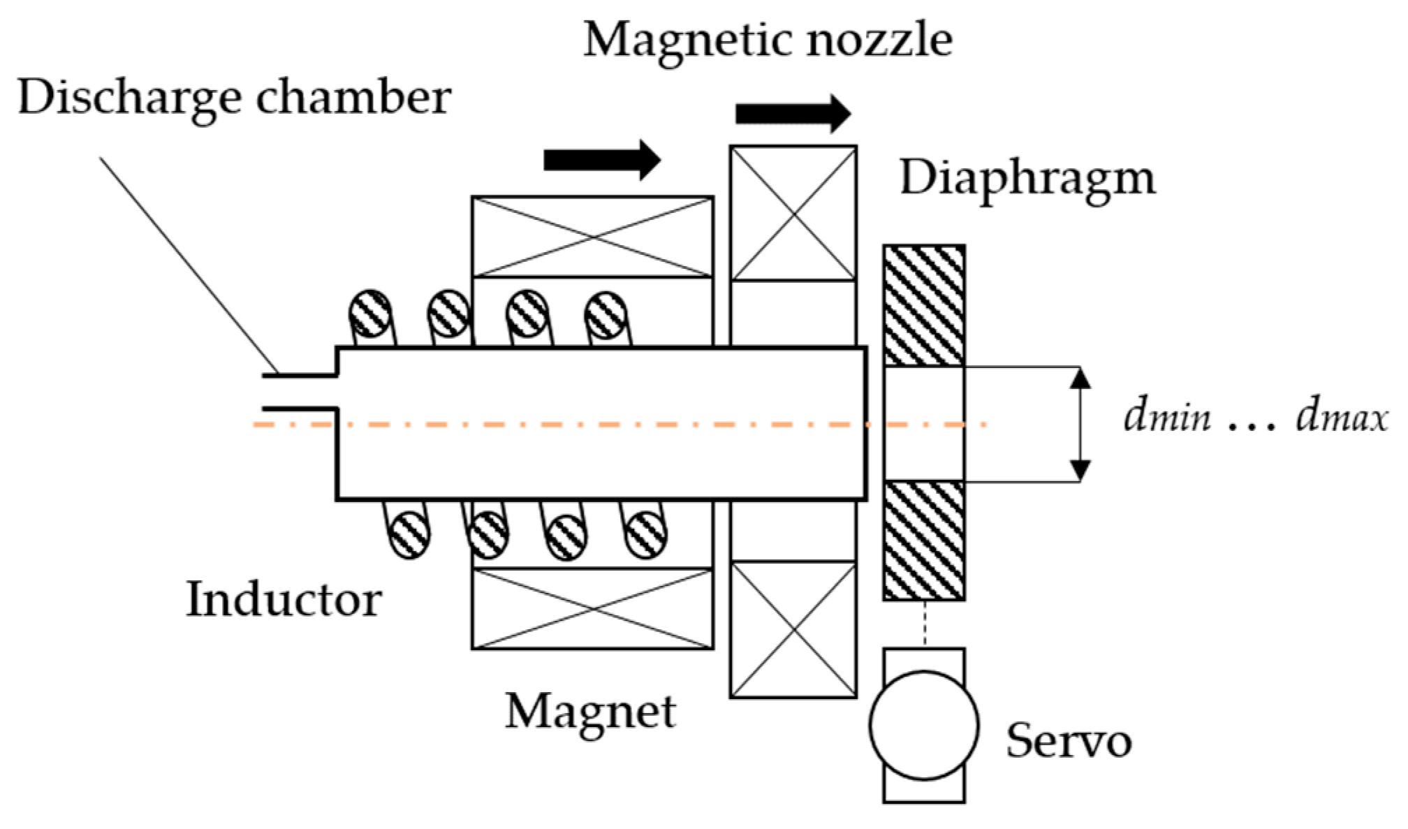
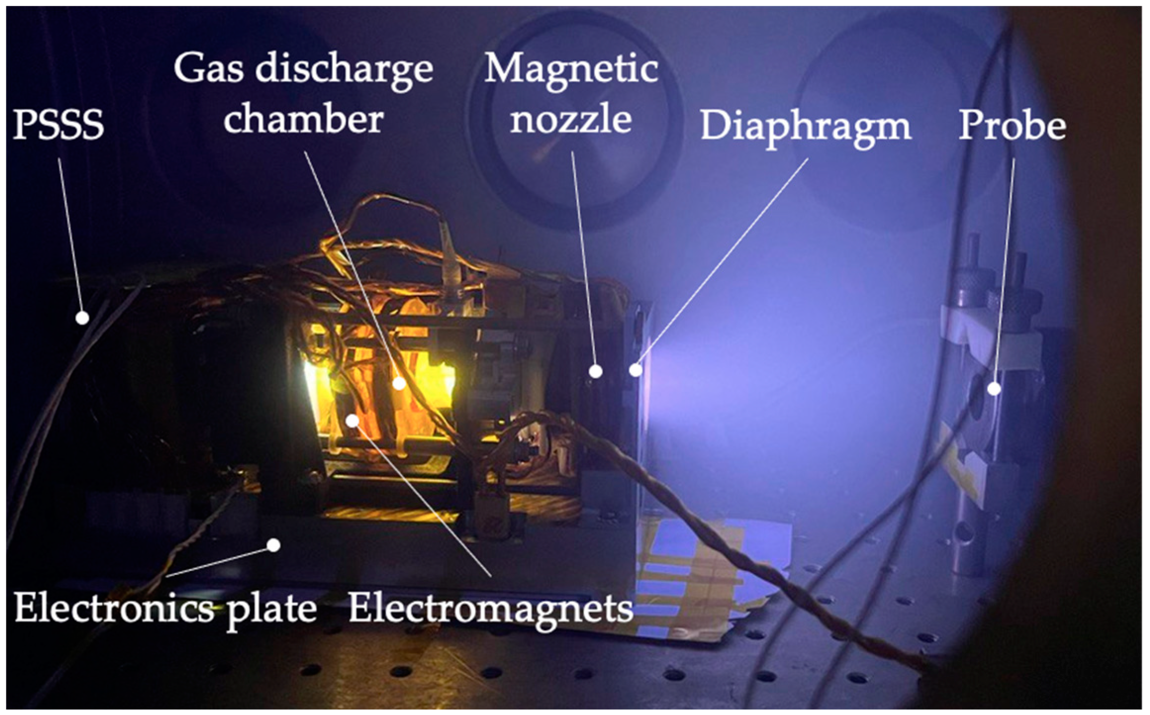
2.1. Electrodeless Plasma Thruster

The structure of the thruster studied is similar to the previously developed and tested electrodeless plasma thrusters [10,35,36,37] but has two specific features in the form of a variable-diameter diaphragm located at the open end of the gas discharge chamber and the magnetic nozzle with the capability of changing the direction of the magnetic field lines. The size of the thruster tested is 2U, corresponding to the following linear dimensions: the height is 100 mm, the length is 200 mm, and the width is 100 mm.
The EPT tested consists of three main parts: the accelerating channel, the electronics plate, and the propellant storage and supply system (PSSS). The EPT’s accelerating channel consists of a gas discharge chamber, a system of electromagnets, a magnetic nozzle, and an inductor (see Figure 1). At the inner diameter at the open end of the gas discharge chamber, a variable-diameter diaphragm is installed. The diameter of the orifice can be changed in the range from 0 mm to 10.5 mm. The orifice diameter is changed by transmitting the torque from the servo drive through a mechanical transmission. It should be noted that a brushless type of servo was used in this work to eliminate desorption and oil vapor flow within the vacuum volume. The orifice diameters, depending on the different control commands on the servo drive, are measured by external instruments. The electronics board includes the radio frequency (RF) generator board and the power supply and control board. The RF generator supplies the inductor with a current at a frequency of 9 MHz. The output power of the RF current can be varied in the range of 0 to 128 W. The power supply consists of 5 independent current channels to supply electromagnets, the magnetic nozzle, the PSSS, and the servo drive. The electronic board has three independent channels for connection to the external power source and the control station; in the current experiment, a laptop with a specific program was used to control the thruster. A more detailed description of the thruster control can be found in [27], where the same electronics are used for another propulsion system.
The PSSS consists of the cylindrical propellant tank, the gas lines, the valve, and the throttle. The magnetic nozzle consists of two independent electromagnets, the axes of which are at an angle of 15° to the axis of the gas discharge chamber.

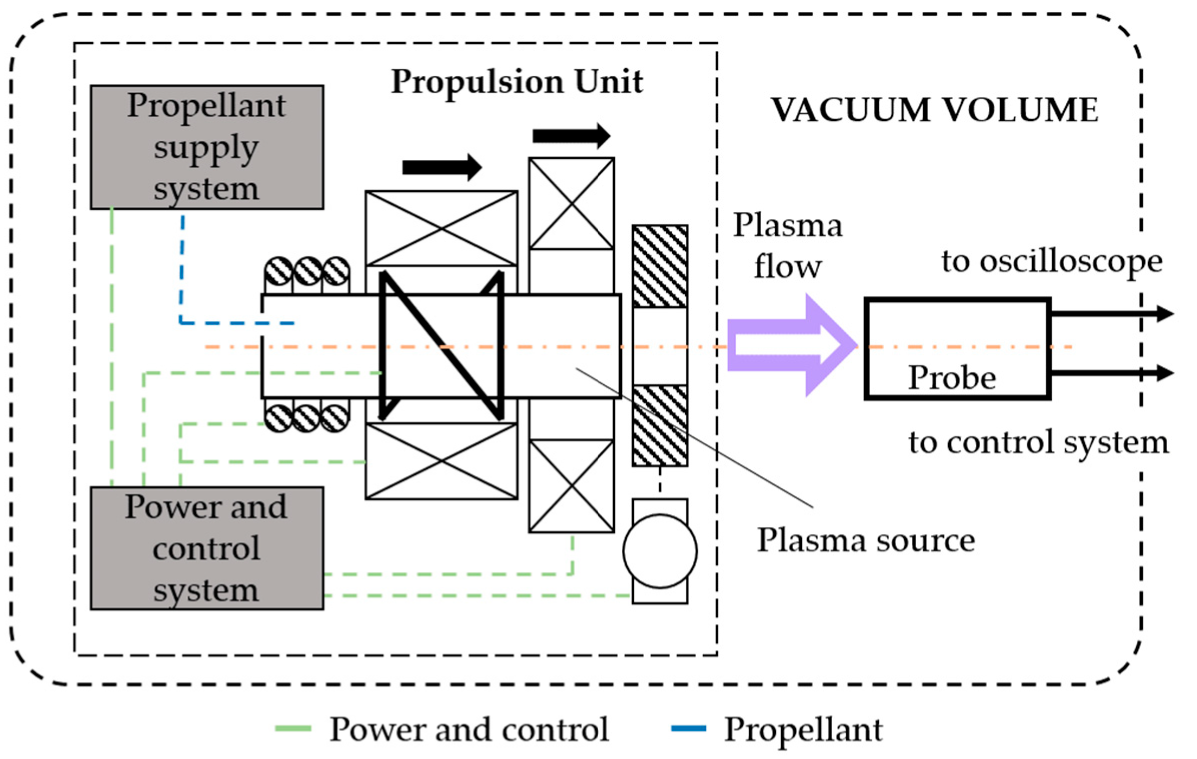
2.2. Experimental Design

The basic scheme of the experiment is shown in Figure 2 and Figure 3.
As part of the experiment, a propulsion system based on an EPT is installed inside the vacuum chamber. The pumping station of the testing facility can maintain a dynamic pressure of about 13 mPa at a flow rate of 60 sccm supplied to the thruster. The propellant used in the experiments is krypton, which is stored in the cylindrical tank of the PSSS. In line with the EPT gas discharge chamber axis, the probe is placed inside the vacuum chamber to analyze the energy characteristics of the exhausted plume ions. The thruster’s gas discharge chamber and the probe are aligned using a semiconductor laser that is placed for the alignment at the entrance grid before the experiments at atmospheric pressure.
The vacuum chamber pumping system consists of two lines—the forevacuum and the high-vacuum line. The forevacuum stage is the oil-free scroll pump ISP-500C by “SHIMADZU Corp., Kyoto, Japan”. The high-vacuum stage is the turbomolecular pump TMP-1003M by “ANEST IWATA, Inc., Yokohama, Japan”. Switching between the lines is carried out by means of gate valves. Pressure measurements in the vacuum chamber are performed by vacuum gauge CC-10 by “Televac, Inc., Miami, FL, USA” and the capacitive manometer ACM 300 by “Atovac Co., Ltd., Yongin, Republic of Korea”.
The parameters of the propulsion system operation are changed by the control system via commands from the laptop [27]. The parameters changed in these experiments are the total power supplied to the EPT and the diameter of the diaphragm, which changes the diameter of the open end of the gas discharge chamber of the source. The change in these parameters at a constant propellant flow rate is seen to have an effect on the following physical parameters that we proposed to measure in this research: the energy distribution of ions and the density of ion current.

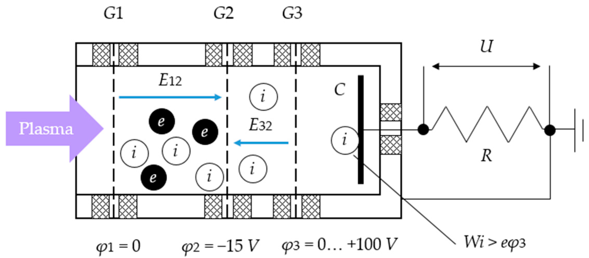
2.3. Diagnostic Probe

The energy parameters of the ionic component of the plasma plume are analyzed using a grid multi-electrode probe [38]. Figure 4 shows the scheme of the probe construction.
G1 provides electrostatic shielding and, therefore, undisturbed measurements of the plasma flow. G1 and the probe body are grounded. G2 separates the plume components by removing plasma electrons with a characteristic temperature in the order of a few electron volts. The typical value of the negative potential on this grid is of the order −15 V. The value of −15 V corresponds to the maximum energy of electrons in the discharge considered under the considering parameters—the power input in the discharge and the pressure in the gas discharge chamber [38]. Choosing this value allows the analyzer to be repelled from most of the electrons present in the exhausted plume. The energy analysis of the ion beam is carried out by varying the retardation voltage on G3 from 0 to a maximum value. In this case, only those ions whose energy W exceeds the value of the retardation potential 3 (assuming that all ions are ionized once) reach the collector. The ion current at the collector is measured by the voltage drop Uc across the collector shunt R.
The voltage on the retardation grid of the probe is automatically controlled using the probe diagnostic kit and software [38].
The main source of measurement errors is the presence of external noises (from equipment at the testing facility), which affect the quality of measurements. The filtering of external noise is performed using software methods. In addition, the measurement error is affected by the transparency of the probe grids (about 45%), defined as the product of the geometric transparency of the grids composing the probe, which is further taken into account in the form of the transparency coefficient K. The measured error for determining the ion current under such conditions is 5%.

3. Experimental Data and Processing

3.1. Operating Modes

The total power supplied to the thruster and the diameter of the channel outlet orifice were used as variable parameters of the EPT operation. Table 1 presents a series of measurements corresponding to the operating parameters studied. In this way, six independent series of experiments were identified: three series correspond to a variation in power at a constant value of the aperture diameter, and the other three series correspond to a constant value of power at a variable-diaphragm diameter.
Some basic operating parameters of the EPT are given in Table 2.

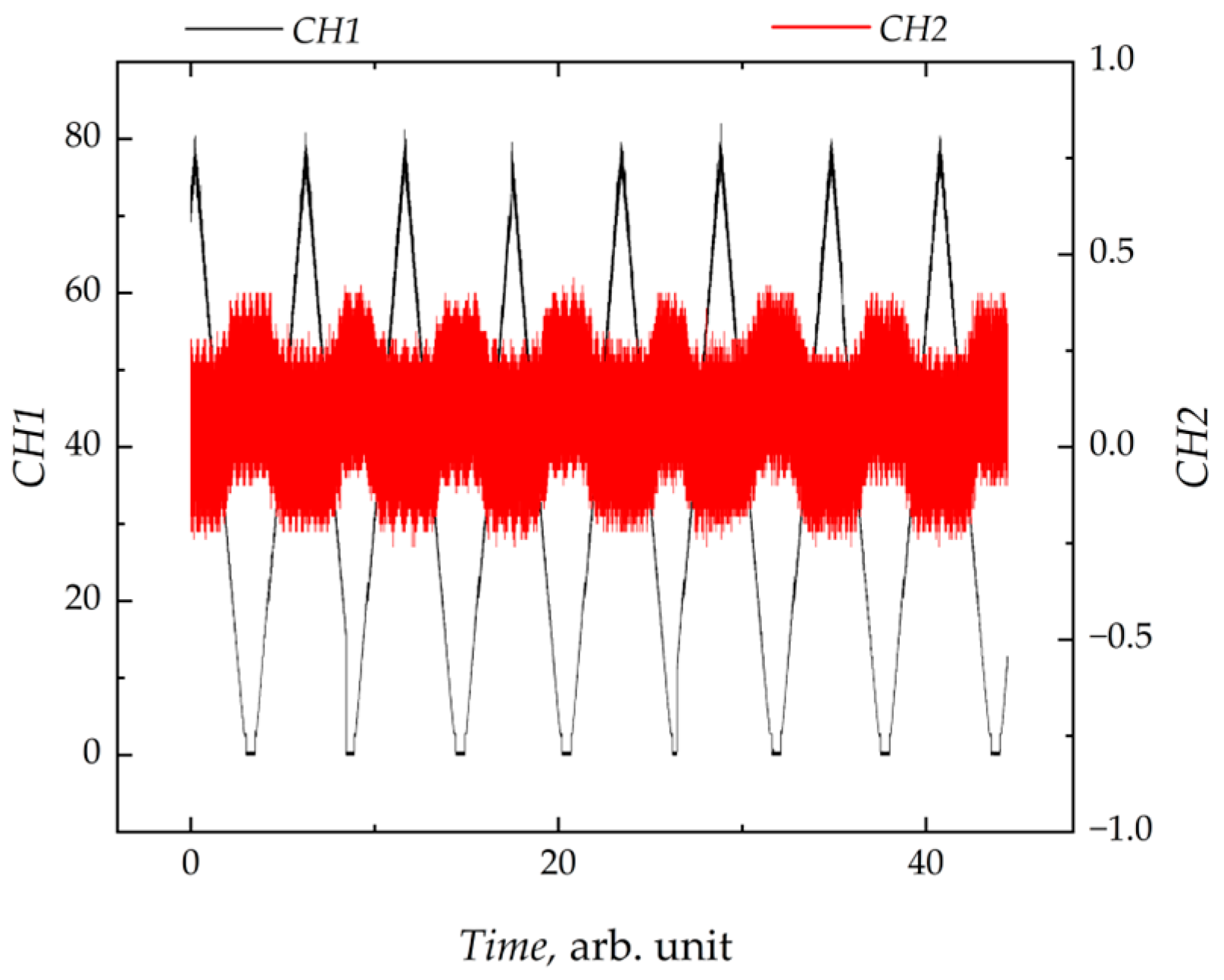
3.2. Experimental Data

During the experiment, the value of the retardation voltage on G3 and the corresponding potential drop Uc on the collector shunt recorded by the instrumentation amplifier were recorded. These two parameters were continuously recorded and displayed on the oscilloscope screen on two independent channels. The nature of the experimental data obtained is shown in Figure 5.
Figure 5 shows that the voltage on the analyzing grid varied periodically in the range from 0 to 80 V. The scanning range of the retardation potential was chosen from the condition of the absence of the ionic current on the collector at the maximum value of the retardation voltage on G3. In order to obtain the set of experimental data necessary for statistical processing, at least 7–9 experimental dependencies were recorded for each series of measurements (Table 1).
The voltage across the shunt resistor is related to the corresponding ionic current at the collector by the following relationship [38]:
I i o n = U c K R A ,
where U c , K , R , and A are the collector shunt voltage, the transparency grid coefficient, the shunt resistance, and the instrumental signal gained, respectively.
Thus, having averaged the obtained data, the retardation characteristics I(φ3) showing the dependence of the ionic current at the collector on the value of the retardation voltage were plotted for each series of experiments on the basis of expression (1) (Figure 6).
Table 3 summarizes the main electrical and geometrical characteristics of the probe used in this study.

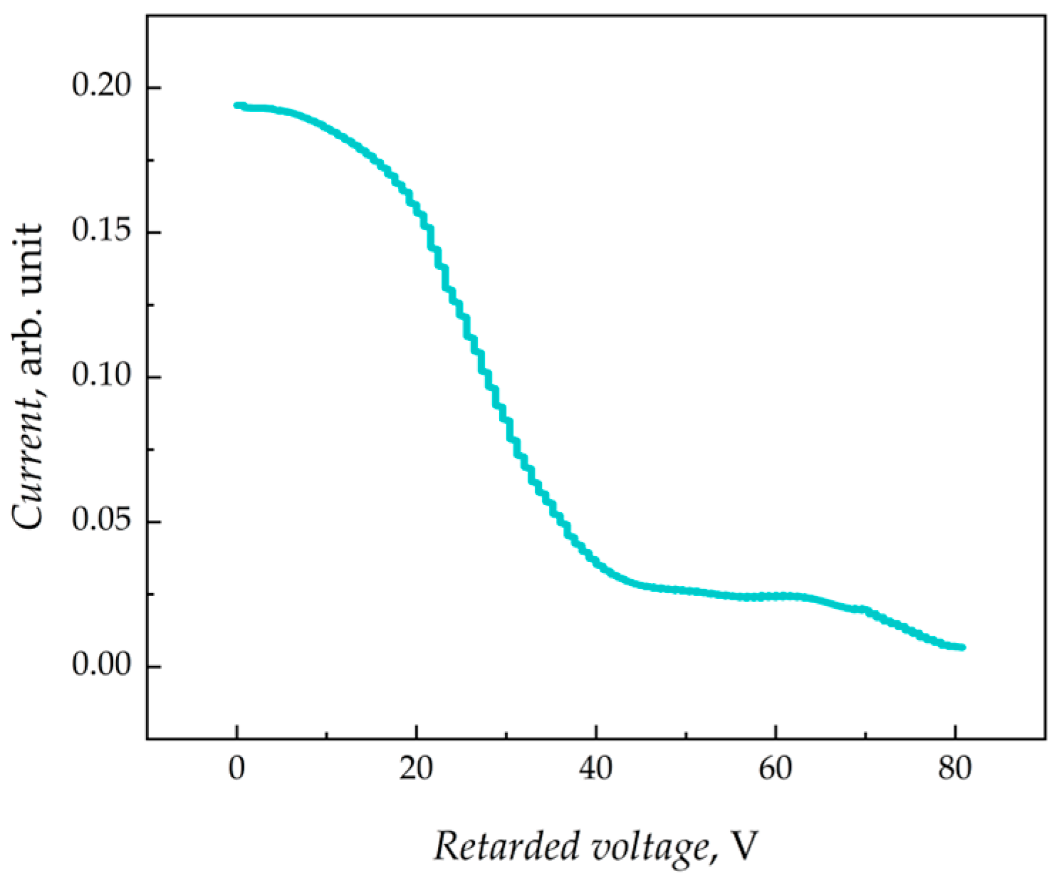
3.3. Data Processing Methodology

The reconstruction of the ion energy distribution functions (IEDFs) was carried out on the basis of the averaged normalized retardation characteristic I0(φ3), normalized with respect to the maximum value of the ion current at the collector and reduced to the form of dependence on the energy of the krypton atoms I0(W). In this case, the expression for the recovery of the IEDF had the following form:
f W = 1 I 0 ( W ) d W = I 0 ( W ) d W
The normalization and post-processing of the averaged experimental retardation characteristics was performed using the Probe DAM software package [38].

4. Results and Discussion

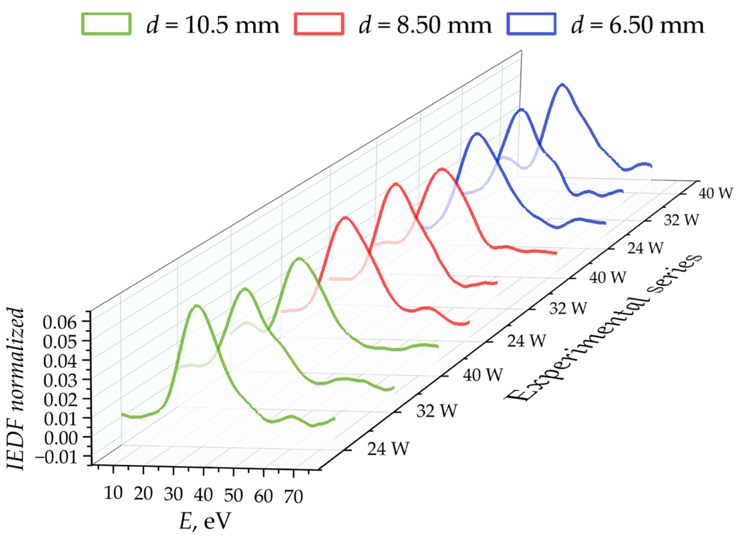
4.1. Experimental IEDF

In accordance with the methodology of the experimental study, the corresponding retardation characteristics were obtained for all investigated EPT operating modes. On the basis of these characteristics, the corresponding normalized IEDFs were reconstructed. The results are shown in Figure 7.
Figure 7 shows that all distribution functions have a main peak. Assuming that its coordinates correspond to the average ion outflow velocity, the average specific impulses for each of the modes studied were calculated according to expression (3). The obtained values of the specific impulse, I s p a v g , are in the range of 757 to 803 s, which is in agreement with the results of similar studies and confirms the efficiency of the propulsion system based on the EPT [35].
I s p a v g = 2 E · e m i · g 2 ,
Here, g is the standard acceleration of gravity, E is the energy of ions, e is the elementary charge, and m i is the mass of ions.

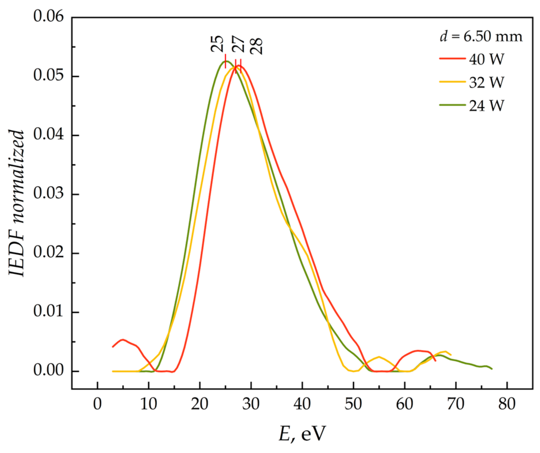
4.2. Analysis of Series with Constant Diameter

In studying the influence of total power consumption on the appearance of the IEDF, it was found that for all modes of EPT operation, there was a characteristic shift in the main peak towards higher energies as the power increased (Figure 8). This is in strict agreement with theoretical considerations since the average kinetic energy of the particles increases with the increasing power input.

4.3. Investigating the Effect of Diaphragm Diameter

As part of this work, we analyzed the effect of aperture diameter on IEDF appearance at constant power consumption (Figure 9 and Figure 10).
Figure 9 and Figure 10 show that changing the aperture diameter results in insignificant changes in the IEDF, which are largely random and cannot be systematized. The key feature here is that the rate of ion efflux from the EPT gas discharge chamber remains virtually unchanged as the aperture diameter is varied. This fact allows us to draw the following important conclusion.
Since a decrease in the aperture diameter leads to an increase in the pressure inside the gas discharge chamber, the temperature of the plasma-forming gas and, as a consequence, the average energy of the ions leaving the gas discharge chamber should increase at constant power under similar conditions. However, as mentioned above, the IEDFs do not change as a function of the diameter of the exit cross-section of the thruster discharge chamber, which allows us to suppose that the mechanism of gas-dynamic ion acceleration is insignificant for low-power (up to 200 W) EPTs at low propellant flow rates (up to 60 sccm of Ar). This proposal can further enhance the conclusions made in the works of Shumeiko et al. [27,33,39], Takahashi et al. [40,41] and Fruchtman [42]. In the works of Shumeiko et al. [27,33,39], it was experimentally determined on-ground and in-orbit that for low-power EPTs (up to 130 W), the gas-dynamic part of the thrust force was less than 10% for low propellant flow rates (up to 10 sccm of Ar). It should be noted that at relatively high flow rates (from 100 sccm of Ar), the dominant part of the thrust force becomes the gas-dynamic part, which is supported by Shumeiko et al. [27,33,39]. The same conclusions were made theoretically by Takahashi [41], and Fruchtman [42]. Further works [41,42] have shown that at low power, the part of the thrust force from the double layer formed at the region of the magnetic field divergence at the exhaust of the thruster is relatively small compared to other components of the thrust force. This is supported by the evidence in Figure 7 and Figure 11 and will be discussed in more detail in Section 4.4. Based on the experimental study of Takahashi et al. [40], it is evidenced that the main role of ion acceleration in low-power EPTs at low propellant flow rates is to enhance the mechanism referred to as electron diamagnetism in the exhaust region of the thruster. This mechanism refers to the electromagnetic part of the thrust force.
Thus, based on the experimental evidence from the observations of the independence of the IEDFs from diaphragm diameter alterations, taking into account the conclusion from previous works examining the acceleration mechanisms in magnetic nozzles [27,33,39,40,41,42], it can be supposed that the dominant mechanisms of ion acceleration in EPTs stem from electromagnetic effects.

4.4. Asymmetry of Energy Distribution Functions

The analysis of the obtained distribution functions shows that the curves do not have significant fluctuations in monotonous growth, but after reaching the peak value, the abnormal deviations of the obtained distribution functions are visible in the right part. The study of the asymmetry of the obtained IEDF was carried out on the basis of the multi-peak Gaussian approximation. Some of the results are shown in Figure 11 and Figure 12 and correspond to the series of measurements shown in Table 2. The approximation is made by the peaks described by the Gaussian distribution function in the following form:
f G v = y 0 + A e x x c 2 2 w 2 ,
where y 0 , A , x c , and w are the baseline of the distribution function, the amplitude value, the coordinate of the peak on the abscissa, and the standard deviation, respectively.
Figure 11 and Figure 12 show that the main part of the IEDF can be represented as a set of two peaks of different intensities: the main low-energy peak with its maximum value in the range 23.5 to 27.3 eV and the minor high-energy peak of lower intensity with its maximum value in a wider range from 31.3 to 38.8 eV. The datasets with non-consistent curvature with other datasets represent the cases when the two distinct peaks—hypothesized to refer to two distinct electromagnetic acceleration mechanisms—collapse. This collapse can be explained as the result of prevailing hypothesized acceleration mechanisms.
The identified curves featuring the presence of two distinct peaks with different intensities in Figure 11 and Figure 12 allow us to hypothesize that there is the presence of two ion acceleration zones within the accelerating channel. These ion acceleration zones can be related to two different electromagnetic acceleration mechanisms. The first mechanism is related to the ion extraction and acceleration by the electrons repelled from the source due to electron diamagnetism [40]. The second mechanism is related to the ion extraction and acceleration by electrons that are accelerated by the Lorentz force [41]. It is observed that as the input power increases, the intensity and width of the high-energy peak decreases. The equalization of the ion velocities is explained by the “collapse” of the acceleration zones due to an increase in the frequency of particle interaction processes in the plasma flow as a result of an increase in the degree of plasma ionization and an increase in the average particle energy. It can be hypothesized that the lower peak refers to ion acceleration via interactions with electrons accelerated by electron diamagnetism. Further investigation of this feature will require additional studies.
In addition, to understand the third peak in Figure 11 and, for some cases in Figure 7 (the one closer to the origin of the coordinates), the following explanation can be considered. Based on the work by Takahashi [41], there are three main components of the thrust force—the thrust from double-layer acceleration, the thrust from electromagnetic effects, and the gas dynamic thrust. It should be noted that Fruchtman et al. [42] found that the component of the thrust force from the pressure of ions on the physical walls of the thruster can be neglected for low-power cases. Based on theoretical calculations and experimental investigations of the components of the thrust force made by Shumeiko [39], the thrust force component from the double-layer acceleration is lower than the component accounting for the electromagnetic effects. This conclusion made by Shumeiko [39] is supported by the experimental data obtained in this study. Based on Figure 7, the peak formation occurs within the power increase and depends on the exhaust orifice diameter that was found by Thakur et al. [43]. Thus, it can be proposed that the third low-energy peak in Figure 11 and, for some cases in Figure 7, relates to the ions accelerated by the double layer formed at the exhaust of the thruster.

4.5. Theoretical Analysis of Exhaust Velocity

To discuss the results obtained further, it can be beneficial to consider the analytical description of the determination of ion velocities. Based on the previously discussed models [39,41,42], the total thrust, T t o t a l , of low-power EPTs can be described by the following expression:
T t o t a l = T p e + T e m a g + T g a s ,
where T p e is the part of the thrust from double-layer acceleration, T e m a g is the part of the thrust from electromagnetic effects, and T g a s is the part of thrust from gas-dynamic acceleration.
The thrust components on the right-hand side can be determined following the theories provided in the following equations [39,41,42]:
T p e = n s k B T e A s ,
T e m a g = 2 π 0 L 0 R i φ B c r r d r d z ,
i φ = 4 π r μ 0 d ( μ 0 N l I R F 0 s i n ω t ) d z ,
T g a s = n = 1 m k n n g m i A s v g a s 2 1 + e T g m i v g a s 2 ,
where n s is the plasma density, k B is the Boltzmann’s constant, T e is the electron temperature, A s is the cross-section of the gas discharge chamber, R is the inner radius of the gas discharge chamber, L is the length of the gas discharge chamber, r is the radial coordinate, z is the axial coordinate, i φ is the azimuthal current in the plasma, B c r is the radial component of the induction of an external time constant magnetic field, μ 0 is the vacuum permeability, d is the diameter of the inductor, N is the equivalent number of turns of the inductor, l is the length of the inductor, I R F 0 is the amplitude value of the inductor current, ω is the angular frequency of the current oscillation in the inductor, k n is the constant indicating the part of the propellant flow rate exhaust from the distinct outlet of the gas discharge chamber, n g is the density of the neutral gas, v g a s is the sound velocity in the gas, and T g is the temperature of the neutral gas.
Since, in this study, the probe by which the ion energy distribution function was determined was located relatively far from the thruster exhaust, it can be supposed that the ions reaching the probe contributed only to the effective velocity of the exhausted particles. The effective velocity of particles leaving the thruster can be determined by the following expression:
v j = T j m k ,
where v j is the effective velocity corresponding to the distinct acceleration mechanism, T j is the distinct thrust component, and m k is the propellant mass flow rate corresponding to either neutral or charged particle acceleration.
To facilitate the analytical description for the evaluation of the experimental results obtained in this study, the effective velocities in units of energy can be considered as follows:
E j = m k v j 2 2 e .
Based on Equations (1)–(11), the following expression for the determination of the energy of particles accelerated by different mechanisms can be obtained as follows:
E p e = 1 2 e m e l [ n s k B T e A s ] 2 ,
E e m a g = 1 2 e m e l [ 2 π 0 L 0 R [ 4 π r μ 0 d ( μ 0 N l I R F 0 s i n ω t ) d z ] B c r r d r d z ] 2 ,
E g a s = 1 2 e m n [ n = 1 m k n n g m i A s v g a s 2 1 + e T g m i v g a s 2 ] 2 .
where m e l is the ionized propellant flow rate and m n is the neutral flow rate.
For the analytical evaluation, the following parameters can be used for calculations for the case of P i n p u t = 32 W: m i = 1.39 · 10 25 kg (for krypton as the propellant), R = 0.01 m, ω = 9 MHz, l = 0.04 m, m ˙ = 3.7 mg/s (60 sccm), and T g = 0.026 eV, B c r —corresponding to the peak at—taken from [39]. Based on the calculations, the corresponding velocities are v p e = 1.87 · 10 2 eV, v g a s = 6.89 · 10 2 eV, and v e m a g = 26.2 eV. The data obtained by using the analytical model are in good agreement with the experimental results. This result can further validate the supposition that the main acceleration mechanism in the low-power EPT operating at low propellant flow rates relates to electromagnetic effects.

5. Conclusions

In this paper, an experimental study of the plasma parameters of an EPT using the in-house-developed retardation potential analyzer is presented. Based on the data obtained, the retardation characteristics for different operating modes were obtained, and the corresponding IEDFs were reconstructed. It was found that as the power consumed by the EPT increases and the IEDF shifts to the higher energy region, which is in strict agreement with theoretical considerations. In addition, based on the obtained distribution functions, the average values of the specific impulse of the EPT were calculated. The values obtained ranged from 757 to 803 s. These results are in agreement with the results of similar studies, which confirm the correctness of the experiment carried out and the prospects of using EPTs as propulsion systems.
This work also shows that changing the diameter of the EPT aperture does not significantly affect the type of IEDF. This allowed us to assess the insignificance of the mechanism of gas-dynamic acceleration in the plasma of the EPT. It also confirms that the main contribution to ion acceleration is made by electromagnetic effects.
It was also shown that the obtained IEDFs can be represented as a set of two peaks described by the Gaussian function: a major peak with a maximum value in the range from 23.5 to 27.3 eV and a minor peak with a maximum value in the range from 31.3 to 38.8 eV. This indicates the presence of two ion acceleration zones. A “collapse” of these two zones was observed as the thruster power consumption increased. This is explained by the increase in the number of charged particles and, consequently, the leveling of their energy characteristics due to the intensification of the interaction processes.

Author Contributions

Conceptualization, A.A.A. and A.I.S.; methodology, A.A.A. and A.I.S.; software, A.A.A. and A.I.S.; validation, A.A.A., A.I.S., A.D.P., P.A.T., S.V.K. and V.D.T.; formal analysis, A.A.A. and A.I.S.; investigation, A.A.A. and A.I.S.; resources, A.I.S.; data curation, A.A.A. and A.I.S.; writing—original draft preparation, A.A.A. and A.I.S.; writing—review and editing, A.A.A. and A.I.S.; visualization, A.A.A. and A.I.S.; supervision, A.I.S.; project administration, A.I.S. All authors have read and agreed to the published version of the manuscript.

Funding

This work was performed at the large-scale research facility “Beam-M” of Bauman Moscow State Technical University following the government task by the Ministry of Science and Higher Education of the Russian Federation (FSFN-2024-0007).

Data Availability Statement

The data that support the findings of this study are available from the corresponding author upon reasonable request.

Conflicts of Interest

The author Aslan D. Pashaev was employed by the company Advanced Propulsion Systems LLC. The remaining authors declare that the research was conducted in the absence of any commercial or financial relationships that could be construed as potential conflicts of interest.

References

  1. Garzaniti, N.; Tekic, Z.; Kukolj, D.; Golkar, A. Review of technology trends in new space missions using a patent analytics approach. Prog. Aerosp. Sci. 2021, 125, 100727. [Google Scholar] [CrossRef]
  2. Choueiri, E.Y. A Critical History of Electric Propulsion: The First 50 Years (1906–1956). J. Prop. Power 2004, 20, 193–203. [Google Scholar] [CrossRef]
  3. Pashaev, A.D.; Shumeiko, A.I.; Telekh, V.D. Determination of the minimum size of a small spacecraft of the cubesat standard for the possibility of using modern propulsion systems. AIP Conf. Proc. 2023, 2549, 050002. [Google Scholar] [CrossRef]
  4. Rafalskyi, D.; Martínez, J.M.; Habl, L.; Rossi, E.Z.; Proynov, P.; Boré, A.; Baret, T.; Poyet, A.; Lafleur, T.; Dudin, S.; et al. In-orbit demonstration of an iodine electric propulsion system. Nature 2021, 599, 411–415. [Google Scholar] [CrossRef]
  5. Douglas Liddle, J.; Holt, A.P.; Jason, S.J.; O’Donnell, K.A.; Stevens, E.J. Space science with CubeSats and nanosatellites. Nat. Astron. 2020, 4, 1026–1030. [Google Scholar] [CrossRef]
  6. Massey, R.; Lucatello, S.; Benvenuti, P. The challenge of satellite megaconstellations. Nat. Astron. 2020, 4, 1022–1023. [Google Scholar] [CrossRef]
  7. Levchenko, I.; Keidar, M.; Cantrell, J.; Wu, Y.; Kuninaka, H.; Bazaka, K.; Xu, S. Explore space using swarms of tiny satellites. Nature 2018, 562, 185–187. [Google Scholar] [CrossRef]
  8. Shkolnik, E.L. On the verge of an astronomy CubeSat revolution. Nat. Astron. 2018, 2, 374–378. [Google Scholar] [CrossRef]
  9. Lev, D.; Myers, R.M.; Lemmer, K.M.; Kolbeck, J.; Koizumi, H.; Palzin, K. The technological and commercial expansion of electric propulsion. Acta Astronaut. 2019, 159, 213–227. [Google Scholar] [CrossRef]
  10. Shumeiko, A.I.; Telekh, V.D.; Mayorova, V.I. Development of a novel wave plasma propulsion module with six-directional thrust vectoring capability. Acta Astronaut. 2022, 191, 431–437. [Google Scholar] [CrossRef]
  11. Resta, E.; Marsilio, R.; Ferlauto, M. Thrust vectoring of a fixed axisymmetric supersonic nozzle using the shock-vector control method. Fluids 2022, 6, 441. [Google Scholar] [CrossRef]
  12. Afridi, S.; Khan, T.A.; Shah, S.I.A.; Shams, T.A.; Mohiuddin, K.; Kukulka, D.J. Techniques of fluidic thrust vectoring in jet engine nozzles: A review. Energies 2022, 16, 5721. [Google Scholar] [CrossRef]
  13. Lee, E. Kang, H.; Kwon, S. Demonstration of thrust vector control by hydrogen peroxide injection in hybrid rockets. J. Prop. Power 2019, 35, 109–114. [Google Scholar] [CrossRef]
  14. Chen, Z.; Wang, Y.; Li, M.; Wu, P.; Wang, Y.; Lu, S.; Zhang, G.; Ren, J.; Tang, H. Plume deflection using an asymmetrical magnetic nozzle for an applied-field magnetoplasmadynamic thruster—An experimental demonstration and numerical analysis. Acta Astronaut. 2023, 209, 82–94. [Google Scholar] [CrossRef]
  15. Takahashi, K.; Imai, R. Two-dimensional deflection of a plasma plume exhausted from a magnetically steered radiofrequency plasma thruster. Phys. Plasm. 2022, 29, 054501. [Google Scholar] [CrossRef]
  16. Caldarelli, A.; Filleul, F.; Charles, C.; Boswell, R.; Rattenbury, N.; Cater, J. Radial characterization of an ion beam in a deflected magnetic nozzle. J. Electr. Prop. 2022, 1, 10. [Google Scholar] [CrossRef]
  17. Shumeiko, A.I.; Jarrar, F.S.; Swei, S.S. Advanced wave plasma thruster with multiple thrust vectoring capability. In Proceedings of the AIAA SCITECH 2022 Forum, San Diego, CA, USA, 3–7 January 2022; p. 2190. [Google Scholar] [CrossRef]
  18. Merino, M.; Ahedo, E. Contactless steering of a plasma jet with a 3D magnetic nozzle. Plasm. Sources Sci. Technol. 2017, 26, 095001. [Google Scholar] [CrossRef]
  19. Stark, W.; Gondol, N.; Tajmar, M. Concept and design of a hall-effect thruster with integrated thrust vector control. J. Electr. Prop. 2022, 1, 21. [Google Scholar] [CrossRef]
  20. Ding, M.; Li, H.; Ding, Y.; Wei, L.; Mao, W.; Yu, D.; Cao, Y. Performance and plume characteristics of a Hall-effect thruster with asymmetrical gas supply. Vacuum 2021, 190, 110285. [Google Scholar] [CrossRef]
  21. Gozhaya, E.; Kudriavtzev, S.; Nikulin, N. SPT thrust vector control. In Proceedings of the 34th AIAA/ASME/SAE/ASEE Joint Propulsion Conference and Exhibit AIAA-1998-3643 (AIAA, 1998), Cleveland, OH, USA, 13–15 July 1998. [Google Scholar] [CrossRef]
  22. Garrigues, L.; Boniface, C.; Hagelaar, G.J.M.; Boeuf, J.P.; Duchemin, O. Performance modeling of a thrust vectoring device for hall effect thrusters. J. Prop. Power 2009, 25, 1003–1012. [Google Scholar] [CrossRef]
  23. Brophy, J.R.; Garner, C.E.; Mikes, S.C. Dawn ion propulsion system: Initial checkout after launch. J. Prop. Power 2009, 25, 1189–1202. [Google Scholar] [CrossRef]
  24. Savytskyy, I.; Jugroot, M. Design and Modeling of a Vectored Electrospray Thruster. In Proceedings of the ASCEND 2022 AIAA-2022-4271 (AIAA, 2022), Las Vegas, NV, USA, 24–26 October 2022. [Google Scholar] [CrossRef]
  25. Luke, J.R.; James, R.; Phipps, C.R.; McDuff, G.G. Laser plasma thruster. Appl. Phys. A 2003, 77, 343–348. [Google Scholar] [CrossRef]
  26. Fedorova, D.K.; Shumeiko, A.I.; Egoshin, D.A.; Pavlov, A.V. Granted Patent in Russia RU2823975C1 Coaxial Ablation Pulse Plasma Engine with Thrust Vectoring. RU2823975C1, 30 November 2023. [Google Scholar]
  27. Shumeiko, A.I.; Telekh, V.D. Direct thrust measurements of 2U-sized bi-directional wave plasma thruster. AIP Adv. 2023, 2171, 170019. [Google Scholar] [CrossRef]
  28. Shumeiko, A.I.; Telekh, V.D.; Ryzhkov, S.V. Starting Modes of Bi-Directional Plasma Thruster Utilizing Krypton. Symmetry 2023, 15, 1705. [Google Scholar] [CrossRef]
  29. Shumeiko, A.I.; Telekh, V.D.; Ryzhkov, S.V. Probe Diagnostics and Optical Emission Spectroscopy of Wave Plasma Source Exhaust. Symmetry 2022, 14, 1983. [Google Scholar] [CrossRef]
  30. Imai, R.; Takahashi, K. Demonstrating a magnetic steering of the thrust imparted by the magnetic nozzle radiofrequency plasma thruster. Appl. Phys. Lett. 2021, 118, 264102. [Google Scholar] [CrossRef]
  31. Zakrzwski, C.; Sanneman, P.; Hunt, T.; Blackman, K. Design of the EO-1 pulsed plasma thruster attitude control experiment. In Proceedings of the 37th Joint Propulsion Conference and Exhibit AIAA-2001-3637, (AIAA, 2001), Salt Lake City, UT, USA, 8–11 July 2001. [Google Scholar] [CrossRef]
  32. Shumeiko, A.I.; Telekh, V.D.; Ryzhkov, S.V. Thrust-vectoring schemes for electric propulsion systems: A review. Chin. J. Aeronaut. 2025, in press. [Google Scholar] [CrossRef]
  33. Shumeiko, A.I.; Pashaev, A.D.; Savelev, P.O.; Telekh, V.D. In-Orbit Demonstration of Bi-directional Electrodeless Plasma Thruster. In Proceedings of the IAF Space Propulsion Symposium, Milan, Italy, 14–18 October 2024; pp. 358–366. [Google Scholar] [CrossRef]
  34. Takahashi, K. Thirty percent conversion efficiency from radiofrequency power to thrust energy in a magnetic nozzle plasma thruster. Sci. Rep. 2022, 12, 18618. [Google Scholar] [CrossRef]
  35. Charles, C.; Boswell, R.W. Laboratory evidence of a supersonic ion beam generated by a current-free “helicon” double-layer. Phys. Plasmas 2004, 11, 1706–1714. [Google Scholar] [CrossRef]
  36. Lynden, W.; Andriulli, R.; Souhair, N.; Ponti, F.; Magarotto, M. Coupling of Fluid and Particle-in-Cell Simulations of Ambipolar Plasma Thrusters. Aerospace 2024, 11, 880. [Google Scholar] [CrossRef]
  37. Charles, C.; Boswell, R.W.; Laine, R.; MacLellan, P. An experimental investigation of alternative propellants for the helicon double layer thruster. App. Phys. 2008, 41, 175–213. [Google Scholar] [CrossRef]
  38. Zhurin, V.V. Industrial Ion Sources. Broadbeam Gridless Ion Source Technolog; Wiley: Hoboken, NJ, USA, 2012. [Google Scholar] [CrossRef]
  39. Shumeiko, A.I. Development and flight-testing of the bi-directional wave plasma accelerator. Ph.D. Thesis, Kazan National Research Technical University, Tatarstan, Russia, 2025. Available online: https://bmstu.ru/svedendoc/disser/index.php?q=dissertation&id=1006&ysclid=m9cs7cdr3q922287555 (accessed on 16 April 2025).
  40. Sumikawa, S.; Takahashi, K. Measurement of a force imparted to a magnetic nozzle by electron diamagnetism. Phys. Plasmas 2024, 31, 034501. [Google Scholar] [CrossRef]
  41. Takahashi, K. Helicon-type radiofrequency plasma thrusters and magnetic plasma nozzles. Rev. Mod. Plasm. Phys. 2019, 3, 3. [Google Scholar] [CrossRef]
  42. Fruchtman, A. Electric field in a double layer and the imparted momentum. Phys. Rev. Lett. 2006, 96, 065002. [Google Scholar] [CrossRef]
  43. Thakur, S.C.; Hansen, A.; Scime, E.E. Threshold for formation of a stable double layer in an expanding helicon plasma. Plasma Sources Sci. Technol. 2010, 19, 025008. [Google Scholar] [CrossRef]
Figure 1. Principal scheme of EPT accelerating channel. The number and geometry of electromagnets are shown schematically.
Symmetry 17 00661 g001
Figure 2. A schematic diagram of the experimental setup. Bold arrows indicate the magnetic field direction of the electromagnets inside the gas discharge chamber. The number and geometry of the electromagnets are shown schematically.
Symmetry 17 00661 g002
Figure 3. Thruster operation during one of the experiments.
Symmetry 17 00661 g003
Figure 4. Scheme of probe construction: G1—entrance grid; G2—electron repelling grid; G3—retard (analyzing) grid; C—collector; e—electron; i—ion [11].
Symmetry 17 00661 g004
Figure 5. Experimental data of one of the modes: CH1—analyzing grid voltage, CH2—amplified collector shunt voltage. The error of the measured grid voltage and amplified collector shunt voltage is 2%.
Symmetry 17 00661 g005
Figure 6. Retardation characteristic I(φ3).
Symmetry 17 00661 g006
Figure 7. Experimental IEDF: measurements corresponding to the same diameter of the diaphragm aperture are highlighted in the same color. The error of measured power consumption and calculated IEDFs are 2% and 5%, respectively.
Symmetry 17 00661 g007
Figure 8. A shift towards higher energies as input power increases. The error of the calculated IEDF is 5%.
Symmetry 17 00661 g008
Figure 9. Investigating the effect of the diaphragm diameter for a power of 32 W. The error of the calculated IEDF is 5%.
Symmetry 17 00661 g009
Figure 10. Investigating the effect of the diaphragm diameter for a power of 40 W. The error of the calculated IEDF is 5%.
Symmetry 17 00661 g010
Figure 11. The decomposition of the functions obtained into harmonics for mode 2 from Table 1. The error of the calculated IEDF is 5%.
Symmetry 17 00661 g011
Figure 12. The decomposition of the functions obtained into harmonics for mode 7 from Table 1. The error of the calculated IEDF is 5%.
Symmetry 17 00661 g012
Table 1. Operating modes.
d, mm24 W32 W40 W
10.5Mode 1Mode 2Mode 3
8.50Mode 4Mode 5Mode 6
6.50Mode 7Mode 7Mode 8
Table 2. Basic parameters of the EPT.
Mass Flow m, mg/sI, A (Magnetic Nozzle)Gas
3.705.00Krypton
Table 3. Probe characteristics.
R, kΩAperture d, mmKA
30.02.502.2125.0
Disclaimer/Publisher’s Note: The statements, opinions and data contained in all publications are solely those of the individual author(s) and contributor(s) and not of MDPI and/or the editor(s). MDPI and/or the editor(s) disclaim responsibility for any injury to people or property resulting from any ideas, methods, instructions or products referred to in the content.

