Article

Robust Online Rotor Time Constant Tuning Method with High-Frequency Current Injection for Indirect Field-Oriented Induction Motor Drives

School of Electrical Engineering, Kookmin University, Seoul 02707, Republic of Korea
Symmetry 2025, 17(10), 1729; https://doi.org/10.3390/sym17101729
Submission received: 3 September 2025 / Revised: 30 September 2025 / Accepted: 5 October 2025 / Published: 14 October 2025
(This article belongs to the Special Issue Applications of Symmetry Three-Phase Electrical Power Systems)

Abstract

For an induction motor operating as a symmetric three-phase system, the performance of indirect field-oriented vector control relies heavily on the accuracy of the rotor time constant. Any inaccuracies result in severe torque errors and compromise dynamic performance because of the coupling between the flux and torque controls. Although conventional IFOC methods are intended to compensate for the rotor time constant error, they rely on induction machine parameters such as the mutual and leakage inductances. This paper proposes an online method for tuning the rotor time constant independent of other parameters. First, an active power model of three-phase symmetric induction motor is selected to estimate the stator resistance based on a model reference adaptive system, which requires only the rotor time constant. Additionally, high-frequency current injection and torque ripple estimation without phase delay or amplitude decay are introduced to compensate for the rotor time constant. When a high-frequency current is injected, the rotor time constant and stator resistance can be simultaneously tuned without depending on other parameters. A high-frequency current is injected only when a rotor time constant error is detected from the estimated stator resistance. This behavior is enabled by the correlation between the stator resistance and the rotor time constant. Simulation results using MATLAB/Simulink regarding the symmetric three-phase induction motor validate the proposed method.

1. Introduction

1.1. Background and Motivation

Indirect field-oriented vector control (IFOC), as a three-phase symmetric system, has been widely used for high-performance induction machine (IM) drives in industrial applications. As IFOC requires only a rotor time constant, it is robust and easy to implement, offering strong dynamic performance and reliability. However, the control performance strongly depends on the accuracy of the rotor time constant, which is the ratio of the rotor’s inductance to its resistance. Although the rotor inductance varies due to flux saturation, it can be predetermined via self-commissioning tests based on the rotor flux level; updating the rotor inductance accordingly can compensate for the effect of its variation. In a squirrel-cage IM, however, the rotor’s impedance cannot be measured accurately, and the process is also time- and labor-intensive. Additionally, the rotor’s resistance varies with its temperature, which cannot be directly measured; this worsens the accuracy of the field orientation [1]. Hence, researchers have attempted to compensate for the rotor time constant rather than estimate every rotor resistance and inductance value.
In [2,3,4,5,6,7], the rotor resistance was calculated based on a steady-state motor equation using the least-squares algorithm while generating transient conditions such as a flux pulse. In [8,9,10], the rotor resistance was estimated using observation methods, including a full-order observer, sliding-mode observer, and Kalman filter. However, because these methods depend on other IM parameters, their performance is limited. Specifically, the stator and rotor resistances vary with temperature and operation frequency [11].

1.2. Literature Reviews and Limitations

Recently, model reference adaptive systems (MRASs) for symmetric three-phase induction motors have been extensively utilized to tune the rotor time constant without being affected by the stator resistance [12,13,14,15,16,17,18,19,20,21,22,23,24,25,26]. This enables direct tuning of the rotor time constant without any need to estimate the rotor resistance. In an MRAS, all output pairs of reference and adaptive models are compared, and the rotor time constant is tuned until the two outputs become equal [12,13,14,15,16]. The comparison between the reference and adaptive models of an MRAS can be based on active and reactive power, dq voltages, and torque [12]. Although various comparison schemes can be employed, most studies have used models capable of estimating the rotor time constant without any knowledge of the stator resistance [13,14,15,16], assuming that the other parameters—including the leakage and mutual inductances—are perfectly known from self-commissioning tests. As mentioned earlier, however, measuring the rotor impedance accurately according to the flux saturation is difficult.
In [17,18,19], low-frequency signals were injected to estimate the rotor time constant. In [17,18], low-frequency signals (20–40 Hz) were injected into the torque-component and flux-component currents. However, as this method utilizes the equations for the IM’s voltage and current models, it is also sensitive to the accuracy of other parameters. Thus, even if a signal with a frequency other than the operation frequency is injected, the estimation accuracy depends on other parameters. In [19], a low-frequency signal was injected via deadbeat control to directly estimate the stator and rotor resistances, as well as the leakage inductance. However, deadbeat control is unsuitable for most applications, and the estimated rotor resistance, whose structure is a bar type, depends on the injected frequency due to the skin effect. Overall, the estimation performance depends on the accuracy of other parameters; moreover, parameters cannot be estimated by simply injecting signals of a specific frequency because IFOC requires the rotor time constant at the operation frequency to be known.

1.3. Paper Organization and Contribution

This paper proposes an online method for tuning the rotor time constant of the three-phase symmetric induction motor through both high-frequency current injection and MRAS-based estimation. First, MRASs with various comparison schemes are reviewed, and the optimal comparison scheme is selected. Unlike conventional MRAS-based rotor time constant compensation, the proposed method leverages an active power model to estimate the stator resistance, which requires only a torque–current table to generate current references according to the torque reference, without any additional IM parameters. The torque–current table is essential for torque linearity in IFOC, even if the rotor time constant is perfectly known. The injection of high-frequency signals provides an additional degree of freedom when simultaneously estimating the rotor time constant and stator resistance. Rather than being continuously injected, the high-frequency signals are briefly delivered when a variation in the rotor time constant is detected based on the estimated stator resistance. To determine the error of the rotor time constant, this study analyzes the variation in the estimated stator resistance according to the rotor time constant error. After injecting the high-frequency signal into the synchronous flux-generating axis, the torque ripple is monitored. If the rotor time constant used in IFOC is perfectly known, the injected signal does not affect the torque output, because the high-frequency signal is filtered. Otherwise, the torque-component current includes the high-frequency signal and directly causes a high-frequency torque ripple. To detect this ripple component, we propose the use of a stator flux observer on the synchronous reference frame. Simulation results about the symmetric three-phase induction motor verify the feasibility of implementing the proposed method in IFOC.

2. Conventional IFOC and Basic IM Equations

The basic IM equations are briefly reviewed in this section. Figure 1 shows the dq equivalent model of an IM in a synchronous reference frame. This dq model can be represented by the following complex voltage equations:
V d q s e = R s I d q s e + d λ d q s e d t + j ω e λ d q s e ,
λ d q s e = L s I d q s e + L m I d q r e ,
λ d q r e = L m I d q s e + L r I d q r e ,
where the superscript e denotes the synchronous reference frame; V d q s e and I d q s e are the dq voltages and currents of the IM, respectively; λ d q s e and λ d q r e are the stator and rotor fluxes in the synchronous reference frame, respectively; Lm and ωe are the mutual inductance and synchronous frequency, respectively; Rs and Rr are the stator and rotor resistances, respectively; and Ls and Lr are the stator and rotor inductances, respectively. Generally, the rotor flux reference frame, where the d-axis is aligned with the rotor flux vector, is adopted to decouple the flux and torque controls. In the rotor flux reference frame, the torque and slip frequency are calculated as
T e = 3 2 p p L m 2 L r I d s e I q s e = K T I d s e I q s e ,
ω s l i p = 1 τ r I q s e I d s e ,
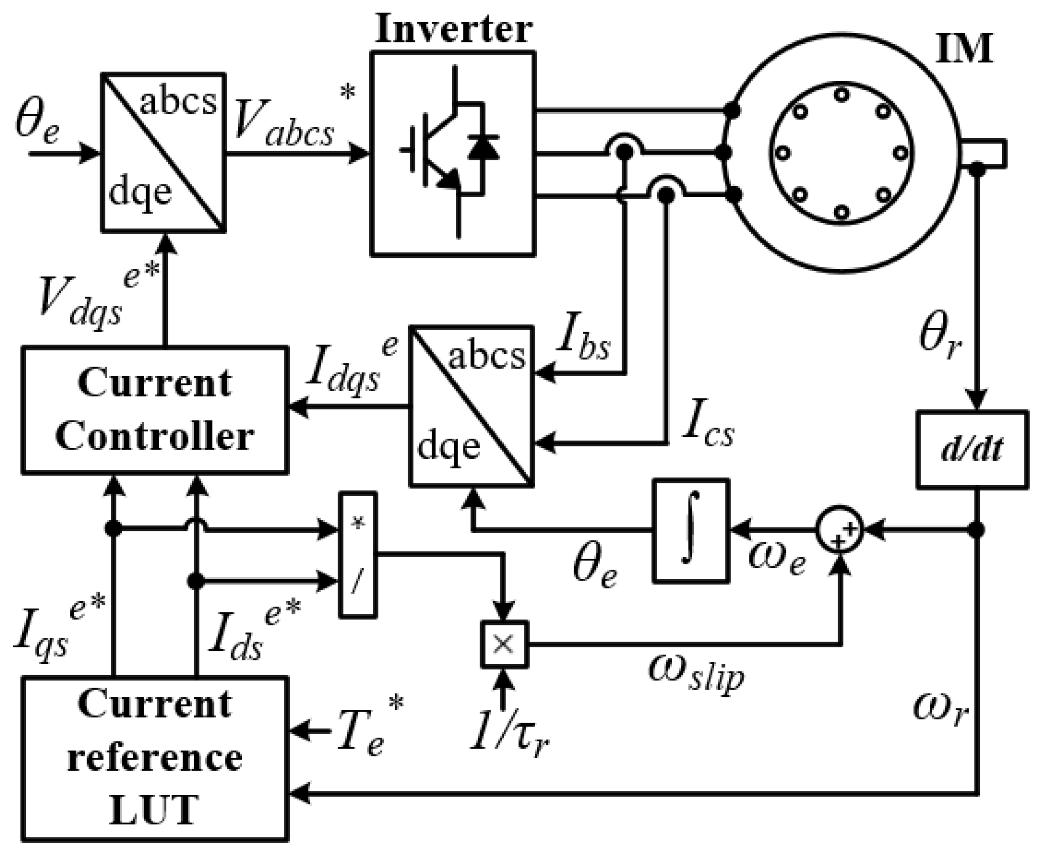
where τr denotes the rotor time constant; pp and KT are the pole pair and torque constant, respectively; and ωslip and ωr are the slip and rotor rotation frequencies, respectively. Figure 2 shows a block diagram for conventional IFOC. Assuming the current command generator to be appropriately determined as a function of the torque reference and rotation speed, the rotor time constant is the sole variable that determines IFOC performance, as shown in Figure 2. However, when other compensation methods, including MRAS-based compensation, are used for online tuning of the rotor time constant, the other parameters in Equations (1)–(5), such as the inductances and stator resistance, become essential. Most studies have adopted models that do not require information regarding the stator resistance, such as the reactive power and dot-product models, and use predetermined inductance values based on the current [13,14,15]. However, measuring the inductance requires additional mechanical equipment and electrical circuits and is also a time- and labor-intensive process.

3. MRAS-Based Stator Resistance Estimation and Detection of Rotor Time Constant Variation

3.1. Selection of MRAS Model for Stator Resistance Estimation

The MRAS concept can be used to compensate for both the rotor time constant and other parameters based on the steady-state IM equations. To estimate the stator resistance, we adopt a convenient MRAS method that has negligible dependency on other parameters.
In IM IFOC, various MRAS models can be derived from the steady-state dq voltage equations in the synchronous rotor flux reference frame:
V d s e = R s I d s e σ L s ω e I q s e ,
V q s e = R s I q s e + L m 2 L r + σ L s ω e I d s e ,
where σ is the leakage factor, defined as 1 − L m 2 /(LsLr). Equations (6) and (7) constitute voltage adaptive models [12], whose parameters include the stator resistance, leakage inductance (σLs), and torque constant inductance ( L m 2 /Lr). Notably, the rotor time constant is included because the synchronous frequency (ωe) is determined based on the rotor time constant in IFOC. The reference models can be obtained from the inverter voltage references, which are the outputs of the current controllers. For example, when the d-axis voltage model is used to estimate the rotor time constant, its performance depends on the accuracies of the stator resistance and leakage inductance.
Various models, such as the reactive power model [12,14,15], the dot-product model of the stator current and rotor fluxes [13], and the active power model [12], have been proposed. The model combining Equations (6) and (7) is independent of one of the parameters constituting the dq voltage models. For example, an MRAS based on the reactive power model is independent of the stator resistance. Table 1 summarizes the parameter dependence of four MRAS models, where “^” indicates an estimated value. As the rotor flux angle is estimated from the indirect field orientation shown in Figure 2, the synchronous angle is the estimated value. Regardless of the MRAS selected, the rotor time constant must be determined, whereby the model contains at least three parameters.
In IFOC, the current reference lookup table is usually adopted for accurate torque regulation, efficient operation, and maximum torque generation within the specified current and voltage limits. Assuming that the error of this current reference mapping is negligible, the active power adaptive model can be redefined as
P s = R s I d s e ^ 2 + I q s e ^ 2 + T e * ω e 1.5 p p ,
where “*” indicates a reference value. If Equation (8) is used as the adaptive model along with the current reference lookup table, instead of the three parameters listed in Table 1, only the stator resistance and rotor time constant would be required. Therefore, we adopt an MRAS based on the active power model for stator resistance estimation and eliminate the requirement for the rotor time constant by injecting a high-frequency current, as detailed in Section 4.

3.2. Effects of Rotor Time Constant Error on MRAS-Based Stator Resistance Estimation

Generally, the injection of high-frequency signals is avoided in inverter-driven motor control because of noise, losses, torque ripple, and other adverse effects. Considering these drawbacks, in the proposed method, a high-frequency current is injected only when a specific condition is satisfied. Specifically, the variation in the rotor time constant based on the estimated stator resistance is monitored, and a high-frequency current is injected only when this variation exceeds a predetermined threshold.
P s _ r e f = 3 2 V d s e ^ I d s e ^ + V q s e ^ I q s e ^ = 3 2 R s I d s e 2 + I q s e 2 + ω r + 1 τ r I q s e I d s e T e / p p ,
P s _ a d p = 3 2 R ^ s I d s e ^ 2 + I d s e ^ 2 + ω r + 1 τ ^ r I q s e ^ I d s e ^ T e * / p p .
The estimated stator resistance R ^ s is adjusted using an integral or proportional–integral (PI) controller to ensure that the adaptive model Ps_adp equals the reference model Ps_ref. The error of the estimated stator resistance corresponds to the second terms of Equations (9) and (10). The slip frequency exhibits no error, regardless of the rotor time constant [16].
ω s l i p = 1 τ r I q s e I d s e = 1 τ ^ r I q s e ^ I d s e ^ .
Therefore, the error of the estimated stator resistance is proportional to the torque error and is calculated as
R ~ s = R ^ s R s = 2 3 ω e T e T e * I s 2 p p ,
where “~” indicates the estimation error, and Is is the stator current amplitude. In IFOC, the torque error is caused by the rotor time constant; thus, the stator resistance error in Equation (12) is related to the rotor time constant error. Before analyzing the torque error, the angle error due to the rotor time constant should be discussed. The following equations involving the currents on the real and estimated rotor flux angles are derived based on the rotor flux angle error:
I d s e I q s e = R θ ~ e I d s e ^ I q s e ^ = I d s e ^ cos θ ~ e I q s e ^ sin θ ~ e I d s e ^ sin θ ~ e + I q s e ^ cos θ ~ e .
By substituting Equation (13) into Equation (11), the angle error can be calculated as
sin θ ~ e cos θ ~ e = tan θ ~ e = τ r τ ^ r 1 I d s e ^ I q s e ^ I d s e ^ 2 + τ r τ ^ r I q s e ^ 2 ,
In Equation (14), the angle error can be assumed to be negligible, along with the rotor time constant error:
tan θ ~ e θ ~ e I d s e ^ I q s e ^ I d s e ^ 2 + I q s e ^ 2 τ r τ ^ r 1 .
Meanwhile, the torque in Equation (4) can be estimated as follows based on Equation (13):
T e T e = K T I d s e I q s e I d s e ^ I q s e ^ K T I d s e ^ I q s e ^ θ ~ e I d s e ^ θ ~ e + I q s e ^ I d s e ^ I q s e ^ = K T θ ~ e I d s e ^ 2 I q s e ^ 2 I d s e ^ I q s e ^ θ ~ e 2 .
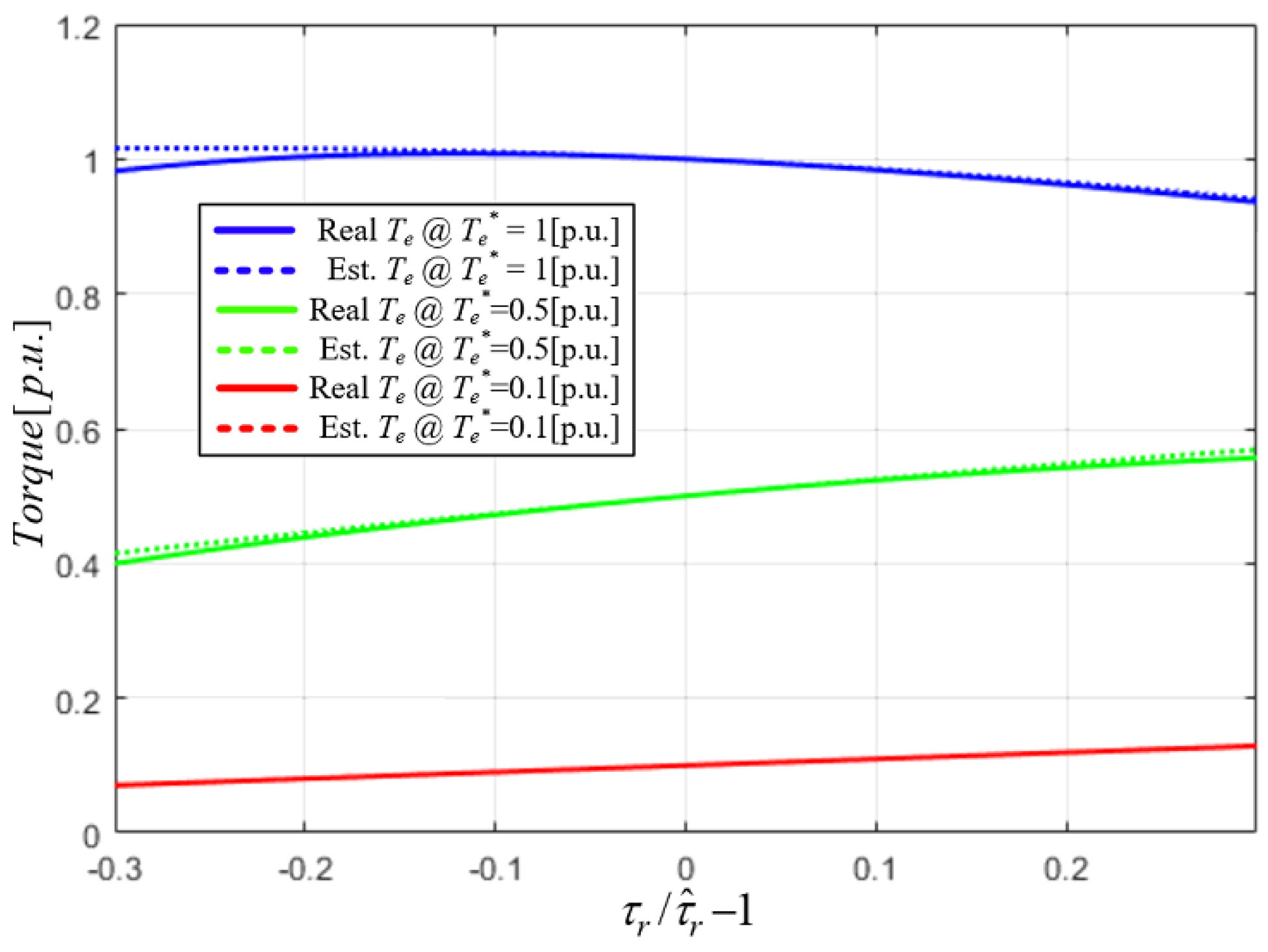
To verify the accuracy of the estimates from Equations (15) and (16), the estimated torque from Equation (16) and the real torque are compared in Figure 3 based on the IM parameters listed in Table 2. Within a 30% error margin for the rotor time constant, the estimated and real values are almost equal. Therefore, by substituting the estimated torque difference from Equation (16) into Equation (12), the effect of the rotor time constant error on the proposed MRAS estimation can be represented as follows:
R ~ s = 2 3 ω e T e * p p I d s e ^ I q s e ^ 2 I s 6 τ r τ ^ r 1 2 + I d s e ^ 2 I q s e ^ 2 I s 4 τ r τ ^ r 1 .
The effect of the rotor time constant error on the stator resistance estimation depends on the operation frequency and torque conditions, as described by Equation (17). Hence, Equation (17) can be used to detect the rotor time constant variation, as detailed in Section 3.3.

3.3. Proposed Method for Detecting Rotor Time Constant Variation

As mentioned in Section 3.1, no degree of freedom is available for determining the stator resistance error without information about the rotor time constant. Specifically, only one of these two variables can be estimated if the other variable is known. The variation in the stator resistance can be defined as
Δ R s = R ^ s R s _ s e t ,
where Rs_set is a set value for the controller. In the initial state, Rs_set can be set to a nominal value. R ^ s is obtained from the MRAS defined by Equations (9) and (10), and ΔRs is calculated in real time. Meanwhile, when the IM operates, both Rs and τr change with the temperature and operation frequency, whereby R ^ s and ΔRs also vary. Although the variation in ΔRs is due to τr and Rs, the proposed detection method exclusively considers the rotor time constant as the variation source and assumes that Rs_set is ideal. Thus, the stator resistance variation in Equation (18) corresponds to the MRAS estimation error from Equation (17), and the rotor time constant error ratio ( X = τ r / τ ^ r 1 ) is calculated based on ΔRs using Equation (17). For simplicity, through variable substitutions, Equation (17) can be rearranged with respect to variable X as follows:
a X 2 + b X + Δ R s = 0 , where X = τ r τ ^ r 1 a = 2 3 T e * ω e I s 6 p p I d s e ^ I q s e ^ 2 , b = 2 3 T e * ω e I s 4 p p I d s e ^ 2 I q s e ^ 2 ,
In Equation (19), a and b are constants calculated based on the current and torque commands, and X is determined by the general solution of a 2nd-order equation:
X = b b 2 4 a Δ R s 2 a ,   if   b < 0 b + b 2 4 a Δ R s 2 a ,   if   b 0 ,
where X is determined assuming that the estimated variation in the stator resistance is caused only by the rotor time constant. Here, X is continuously estimated and managed to be a low value, X remains near zero, so the smaller root of | X | is selected. Also, in practical IM control, the d-axis current is equal or smaller than the q-axis current because of MTPA operation or magnetic saturation, or field-weakening control, so that the only second case solution of (20) is adopted. Therefore, while the exact variation in the rotor time constant is difficult to predict, an approximate value can be obtained from X. When both parameters are correct, X is 0; furthermore, as the errors occur in both values, the absolute value of X increases. Therefore, a boundary value, Xb, is used to determine whether a high-frequency current should be injected:
X X b ,
For example, if a variation of 5% in the rotor time constant is permissible, Xb is set to 0.05 or less. Injecting a high-frequency current provides an additional degree of freedom for estimation, allowing both the stator resistance and rotor time constant to be accurately estimated, as detailed in Section 4.

4. Simultaneous Estimation of Stator Resistance and a Rotor Time Constant Through High-Frequency Current Injection

4.1. Overview

As Equation (3) indicates, the steady-state torque is proportional to the dq-axis currents; however, the dynamic torque can be represented by the dynamic equation for the rotor flux:
λ d r e = 1 / τ r s + 1 / τ r L m I d s e ,
T e = 3 2 p p L m L r I q s e λ d r e = K T I q s e 1 / τ r s + 1 / τ r I d s e .
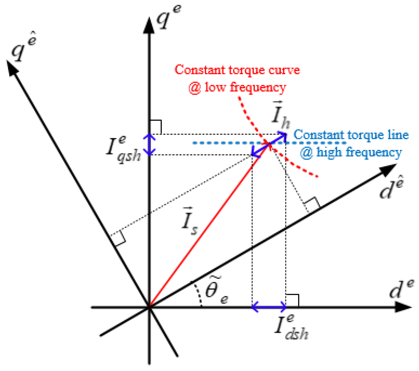
The rotor flux is determined by the low-pass-filtered d-axis current, and the dynamic torque is proportional to the rotor flux and q-axis current. Thus, the torque remains constant if the frequency of the signal injected into the d-axis current reference substantially exceeds the cutoff frequency of the low-pass filter. Accordingly, the constant-torque curve of the IM is divided into low-frequency and high-frequency components. The low-frequency constant torque curve is plotted such that the product of the d-axis and q-axis currents is constant. Conversely, the high-frequency constant-torque curve becomes parallel to the d-axis.
Figure 4 shows the constant-torque curves with the current vector in the synchronous rotor flux reference frame. If the rotor time constant has no error and the high-frequency signal is injected into the d-axis current, no torque ripple occurs. However, due to the angle error, a part of the injected high-frequency signal is introduced into the q-axis current, which causes a torque ripple as large as the angle error. Specifically, the rotor time constant error results in torque ripple, the amplitude of which is proportional to the error when the high-frequency current is injected into the estimated d-axis current. Hence, we inject the high-frequency signal into the estimated d-axis current and track the no-torque-ripple point by adjusting the rotor time constant used in IFOC.

4.2. High-Frequency Current Injection and Rotor Time Constant Compensation

When a high-frequency signal is injected into the estimated d-axis current, the dq-axis current references can be calculated as follows:
I d s e ^ I q s e ^ = I d s 0 e ^ + I h sin ω h t I q s 0 e ^ ,
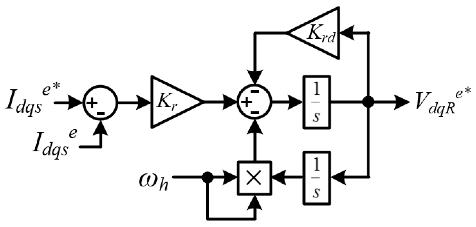
where Ih and ωh are the amplitude and frequency of the injected signal, respectively, and the subscript 0 indicates the DC component. In conventional IFOC, a PI controller is used to regulate the dq-axis currents, which does not guarantee high-frequency regulation. Additionally, the simple voltage injection used in low-speed sensorless control is incompatible with the current injection described by Equation (24) because of the dq coupling effects that arise with increasing operation speed [19]. Thus, the proposed method employs an additional resonant controller that can be easily implemented with double integrals, as shown in Figure 5, where Kr is the resonant control gain and Krd is the damping ratio. This resonant controller eliminates steady-state errors at the target frequency, regardless of errors in the rotor time constant or angle [27].
When the injected current is adjusted using the resonant controller depicted in Figure 5 and a conventional PI controller with zero steady-state error, the dq-axis currents on the rotor flux reference frame can be written in terms of the angle error as
I d s e I q s e = I d s 0 e + I h sin ω h t cos θ ~ e I q s 0 e + I h sin ω h t sin θ ~ e = I d s 0 e + I d s h e I q s 0 e + I q s h e ,
where the subscript h denotes the high-frequency component. The q-axis current has a high-frequency term as large as the angle error, which causes a high-frequency torque ripple (Th).
T e = K T I q s 0 e + I q s h e 1 τ r s + 1 τ r I d s 0 e + I d s h e K T I d s 0 e I h sin ω h t sin θ ~ e = T h sin ω h t sin θ ~ e T h sin ω h t θ ~ e ,
where the rotor flux contains only a DC component because the high-frequency signal does not affect the rotor flux. As the torque contains information about the angular error, the rotor time constant can be corrected based on the estimated torque. Figure 6 illustrates the extraction of the angle error information from the estimated torque. A PI controller is used to generate the compensation term Δτr, which is added to the rotor time constant to calculate the slip frequency.
1 / τ r _ i = 1 / τ r _ s e t + 1 / Δ τ r ,
where τr_i is the rotor time constant used for the indirect field orientation, and τr_set is the value set to determine τr_i for the controller. Also, the PI gains need to be determined by considering the amplitude of the injected torque ripple because the input value is proportional to T h . As shown in Figure 6, this compensation method based on the high-frequency signal depends on the accuracy of the estimated torque T ^ e . Hence, a method should be devised to estimate the torque along with the high-frequency-ripple term.

4.3. Torque Estimation with Zero Phase Delay and Decay [23]

The electrical torque of the IM can be calculated as the cross-product of the stator current and flux vectors. To minimize reliance on other parameters, the torque is estimated based on the stator fluxes. In conventional stator flux-oriented direct vector control, the stator fluxes are estimated by integrating all the stator voltages except the stator resistance voltage drop:
λ d q s s = V d q s s R s I d q s s d t ,
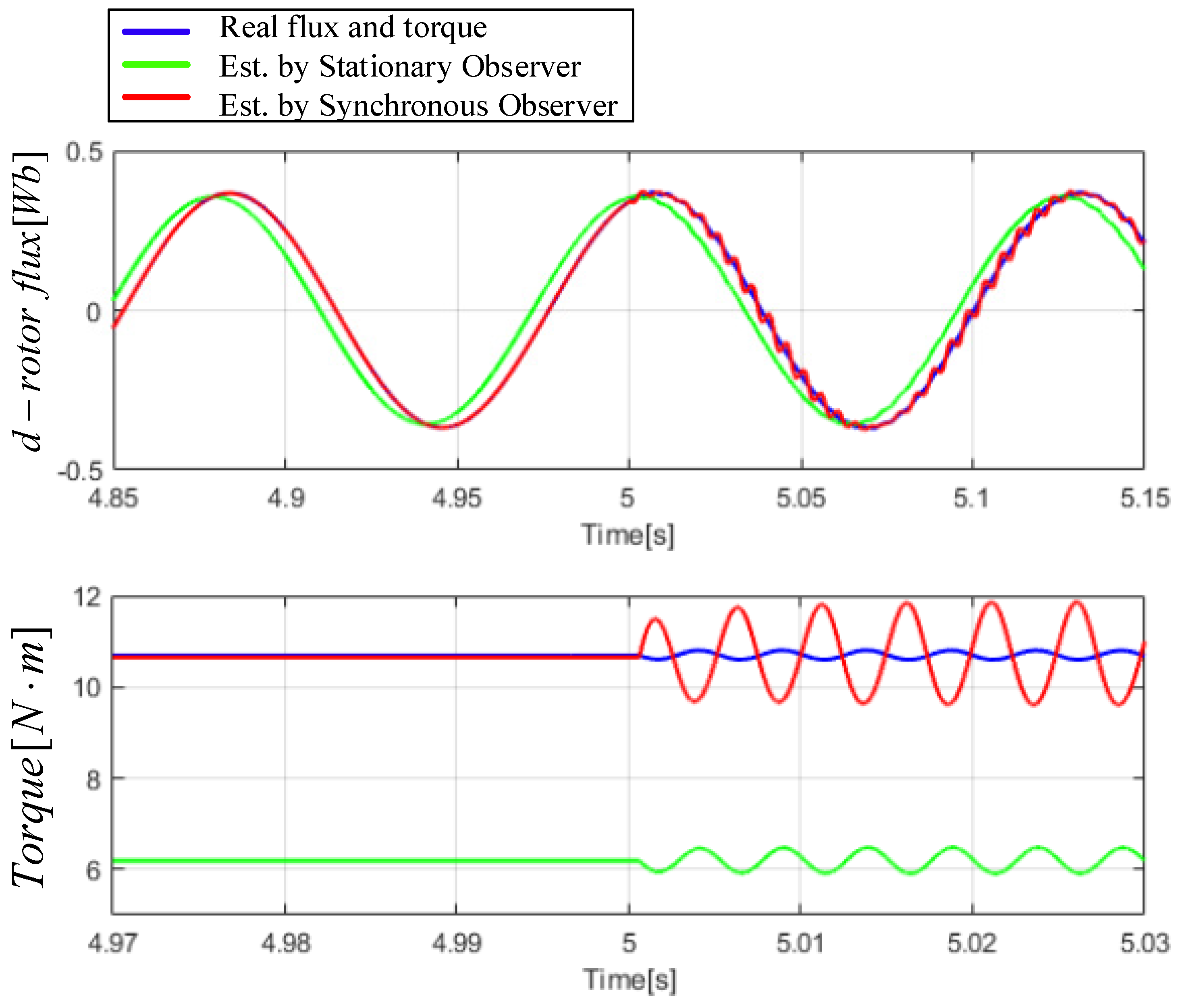
To avoid integrating the DC offset caused by the initial condition error that occurs during rapid variations in either the amplitude or frequency of the stator voltage, high-pass filters are usually applied to the output of Equation (28) [22]. However, a high-pass filter compromises the estimation accuracy at low frequencies. Therefore, in [22], a stator flux estimator without a high-pass filter was proposed, and closed-loop DC offset compensation was applied. By regulating the closed-loop gain based on the synchronous frequency, the estimation performance was enhanced. However, stator flux estimators in the stationary reference frame, such as those in Equation (29) and [22], are inappropriate for high-frequency signal injection. Figure 7 shows the estimated stator fluxes. The torques are calculated as the cross-product of the estimated fluxes and measured currents, with the operation speed and torque output set to 0.1 and 1 p.u., respectively. A high-frequency (200 Hz) current of 0.5 A is injected from the center point as described in Equation (24), and a rotor time constant error of +30% is applied. Before the high-frequency current is injected, the stator flux estimate obtained from Equation (28) and the high-pass filter suffer a phase delay and an amplitude decay under low speed. Conversely, the stator estimation method in [22] performs better before the injection of the high-frequency current. However, the flux and torque estimated using this method of high-frequency current injection exhibit significant errors. Specifically, the estimated torque displays phase and amplitude errors. Thus, both methods are inappropriate for estimating the torque when the high-frequency current is injected.
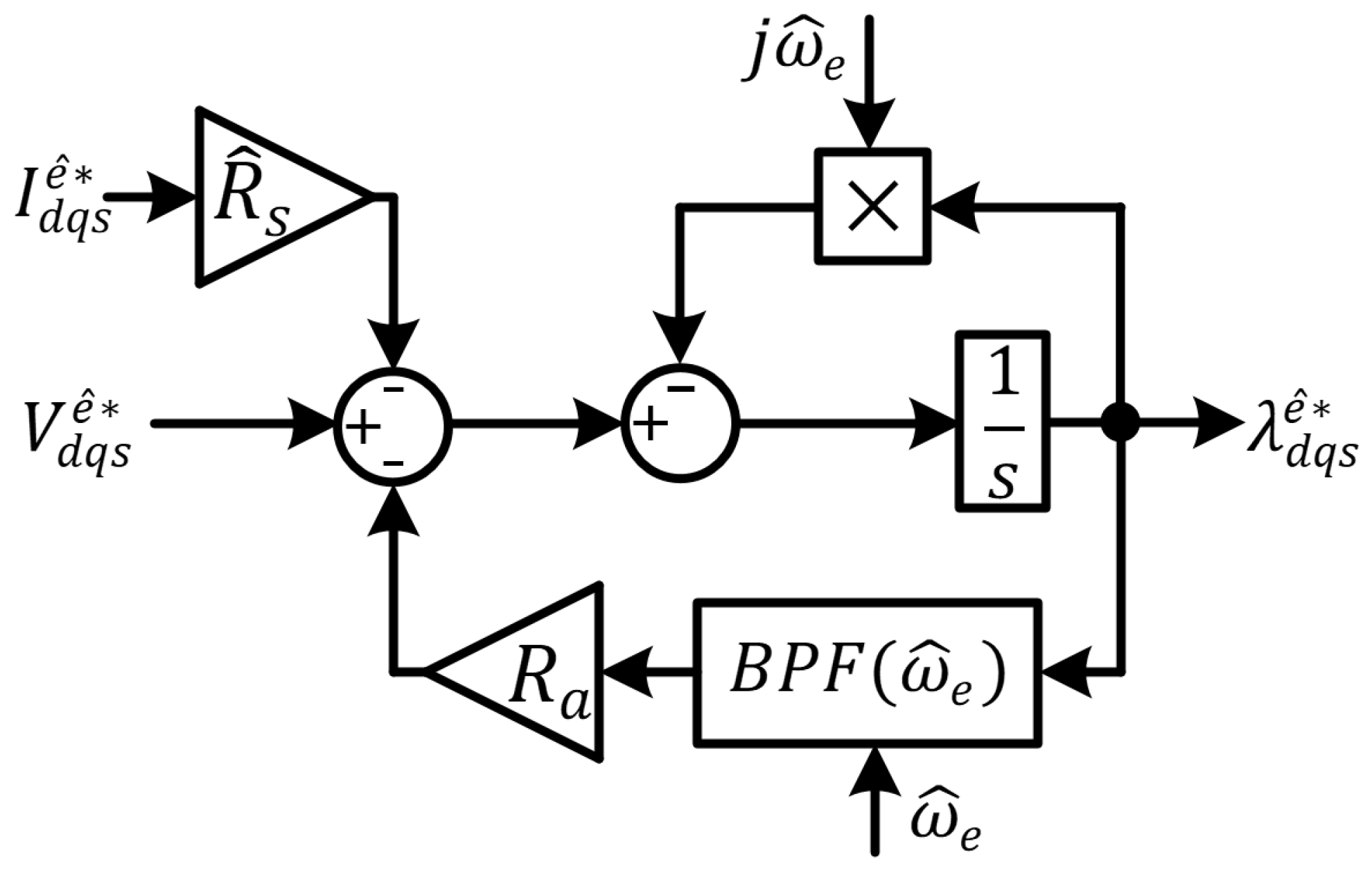
To estimate the torque without any phase delay or amplitude error, we use a stator flux estimator in the synchronous reference frame [23]. This estimator is designed simply based on Equation (1), and it determines the stator fluxes using DC values, with the steady-state stator voltages and currents also being DC values. However, the general solutions of the stator fluxes based on Equation (1) contain both DC and AC components:
λ d q s e = λ d s _ d c e + j λ q s _ d c e + λ a c sin ( ω e t ) + j cos ( ω e t ) ,
where only λ d q _ d c e is meaningful, and λac is generated due to the initial condition errors mentioned earlier. The AC term with the synchronous frequency ωe either increases or does not disappear due to the lack of damping impedance at the synchronous frequency. To eliminate this AC component without affecting the flux estimation performance, we employ an active resistance with a bandpass filter [23]. The specific structure of the synchronous estimator and the mechanism of BPF A-damping are illustrated in Figure 8, where ζ is the damping ratio in BPF A-damping, Ra is the applied active resistance, and u and y are the input and output signals, respectively.
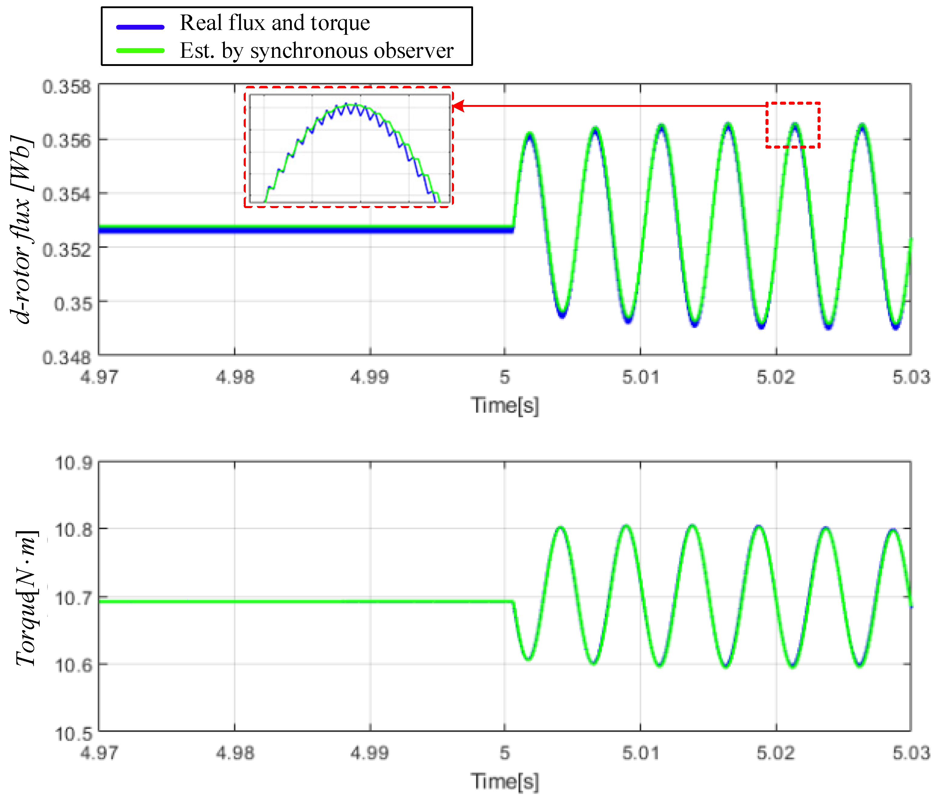
Figure 9 shows the results of simulating the flux and torque estimation with the injection of the high-frequency current under the conditions corresponding to Figure 7. A comparison between Figure 7 and Figure 9 shows that the estimator in the synchronous reference frame outperforms the conventional methods on the stationary reference frame, especially after the injection of the high-frequency current.

4.4. Proposed Method for Online Tuning of Rotor Time Constant

High-frequency current (or voltage) injection is commonly used for sensorless operation and parameter estimation. However, it can introduce additional losses and acoustic noise, making continuous high-frequency injection impractical for certain applications. Accordingly, this work proposes selectively enabling the injection only when needed.
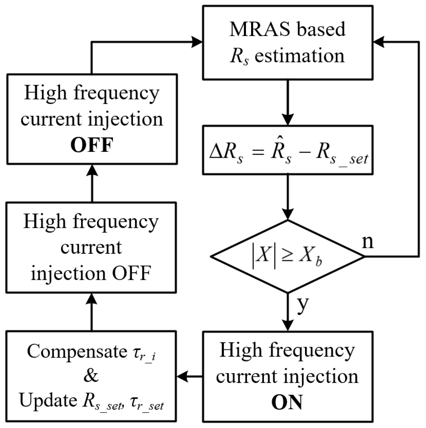
Figure 10 presents a flowchart illustrating the proposed online method for tuning the rotor time constant in IFOC. First, the MRAS-based stator resistance estimation yields R ^ s , whereafter the stator resistance variation ( Δ R s ) and rotor time constant error ratio (X) are calculated. If X is within its present threshold (Xb), the initial state is restored to enable normal operation without injecting any high-frequency current. Otherwise, if X exceeds Xb, which is denoted by y in Figure 11, a high-frequency current is injected to simultaneously compensate for the rotor time constant and stator resistance. The stator resistance and rotor time constant are estimated in a closed loop, with their accuracies during high-frequency current injection being guaranteed through recursive compensation. Meanwhile, Rs_set and τr_set are updated for the next normal and high-frequency current injection modes. This procedure is maintained until the two parameters converge. Then, the injection of the high-frequency current is ceased to restore normal operation. The complete control block diagram, including the proposed method, is shown in Figure 11, where our proposal is highlighted in red and enclosed within the blue box. In MRAS-based Rs estimation, the rotor time constant variation is always predicted based on R ^ s and X, and high-frequency current injection is initiated when the condition in Equation (21) is satisfied, which is denoted by y in Figure 11. Additionally, during the injection of the high-frequency current, R ^ s and Δτr are recursively fed back to the torque and stator resistance estimates, respectively.

5. Simulation Results

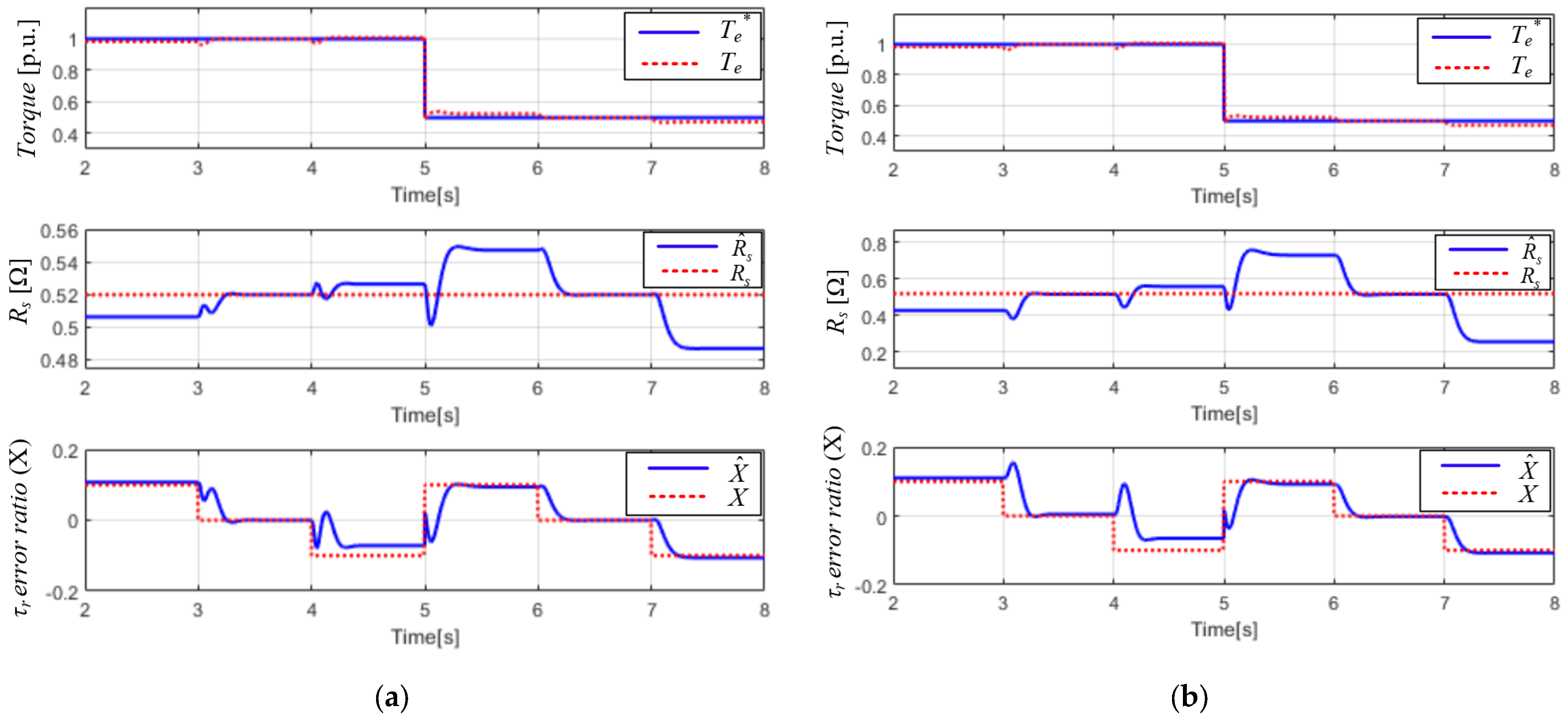
To evaluate the proposed online tuning method, simulations were conducted on the IM and inverter considering the conditions listed in Table 2. In the simulations, we set Xb = 0.1, the injected high-frequency current amplitude to 0.5 A, and its frequency to 200 Hz. The choice of Xb depends on the required parameter-estimation accuracy; a smaller Xb keeps the phase-angle error smaller but can trigger more frequent injections. The injection frequency and amplitude should be chosen in accordance with the control system’s sampling rate and the achievable sensor accuracy. Figure 12a,b display the performance of the proposed method in detecting the rotor time constant error ratio (X) based on the R estimate. The rotor resistance was adjusted to vary X from +10% to −10%, and the torque reference was changed at the center point. As shown in Figure 12a, for a speed of 0.1 p.u., the torque control and estimated Rs were ideal when X was 0. However, when X was adjusted to 0.1 and −0.1, the X ^ estimate obtained using Equation (20) approached the real value. The error between the real and estimated X values was due to the assumed approximations in Equations (16) and (17). Figure 12b shows the results obtained using the same simulation setup for a speed of 1 p.u. Although X varied, the change in the Rs estimate was much larger than that shown in Figure 12a because the ratio of the power loss to the stator resistance, including the active power, decreased as the operation speed increased. The estimated Rs variation at full torque exceeded that at half torque. Despite this variation in the estimated Rs due to the operation speed and torque, the error ratio of the estimated rotor time constant accurately approximated the real error ratio; this indicates that the proposed detection method for X suitably reflected various operation conditions, as intended.
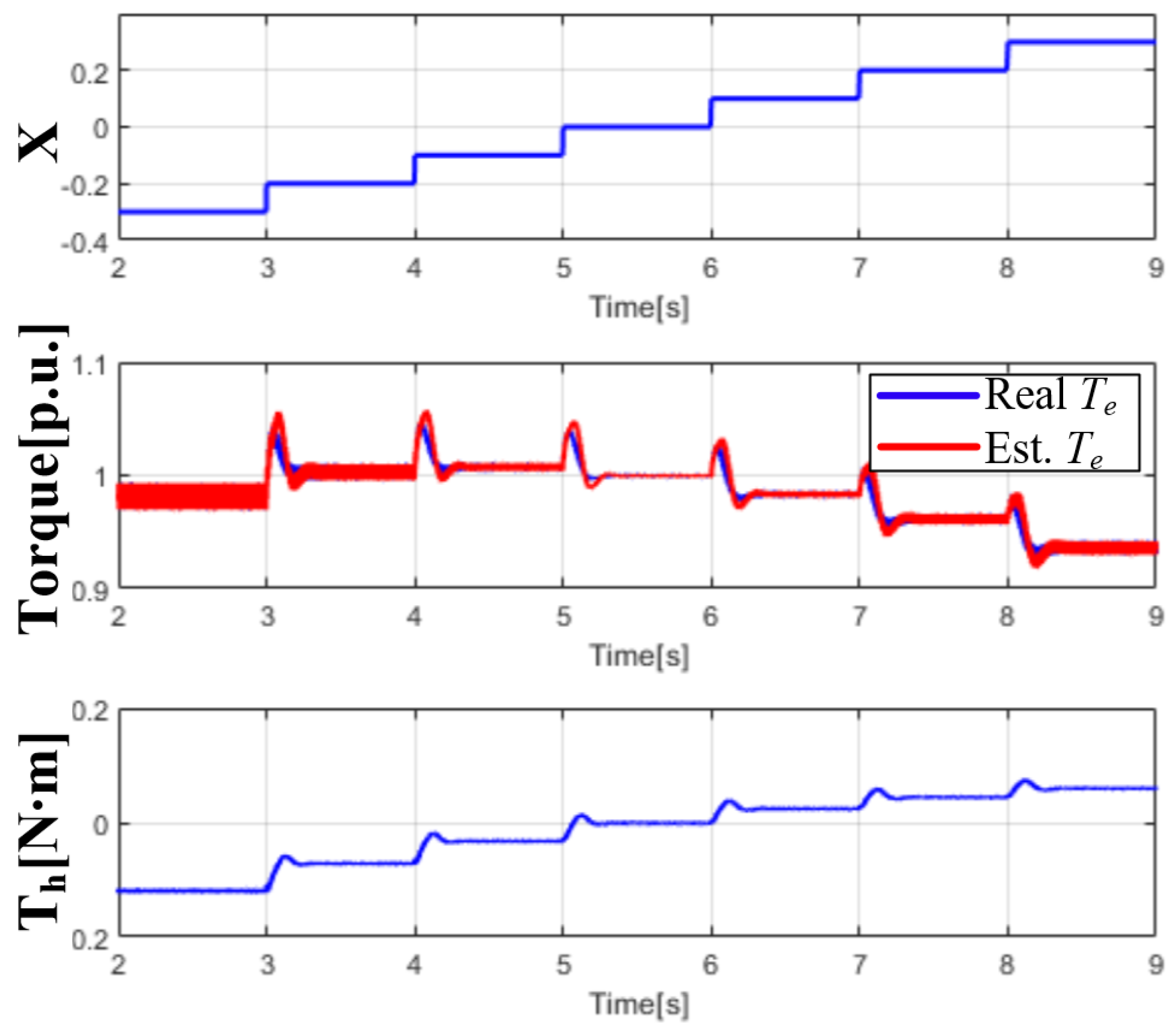
Figure 13 compares the real torque and the processed torque component Th corresponding to the torque ripple shown in Figure 6, which is induced by the injected high-frequency current and the rotor time constant error. The rotor resistance was adjusted to vary the rotor time constant error ratio from −30% to +30% in increments of 10%, and a high-frequency (200 Hz) current of 0.5 A was injected into the d-axis current estimated using Equation (24). The torque included a ripple component proportional to the rotor time constant error, and the processed torque component represented the torque ripple amplitude. Thus, if the torque with the high-frequency ripple was suitably estimated, the rotor time constant could be tuned online based on the processed torque component.
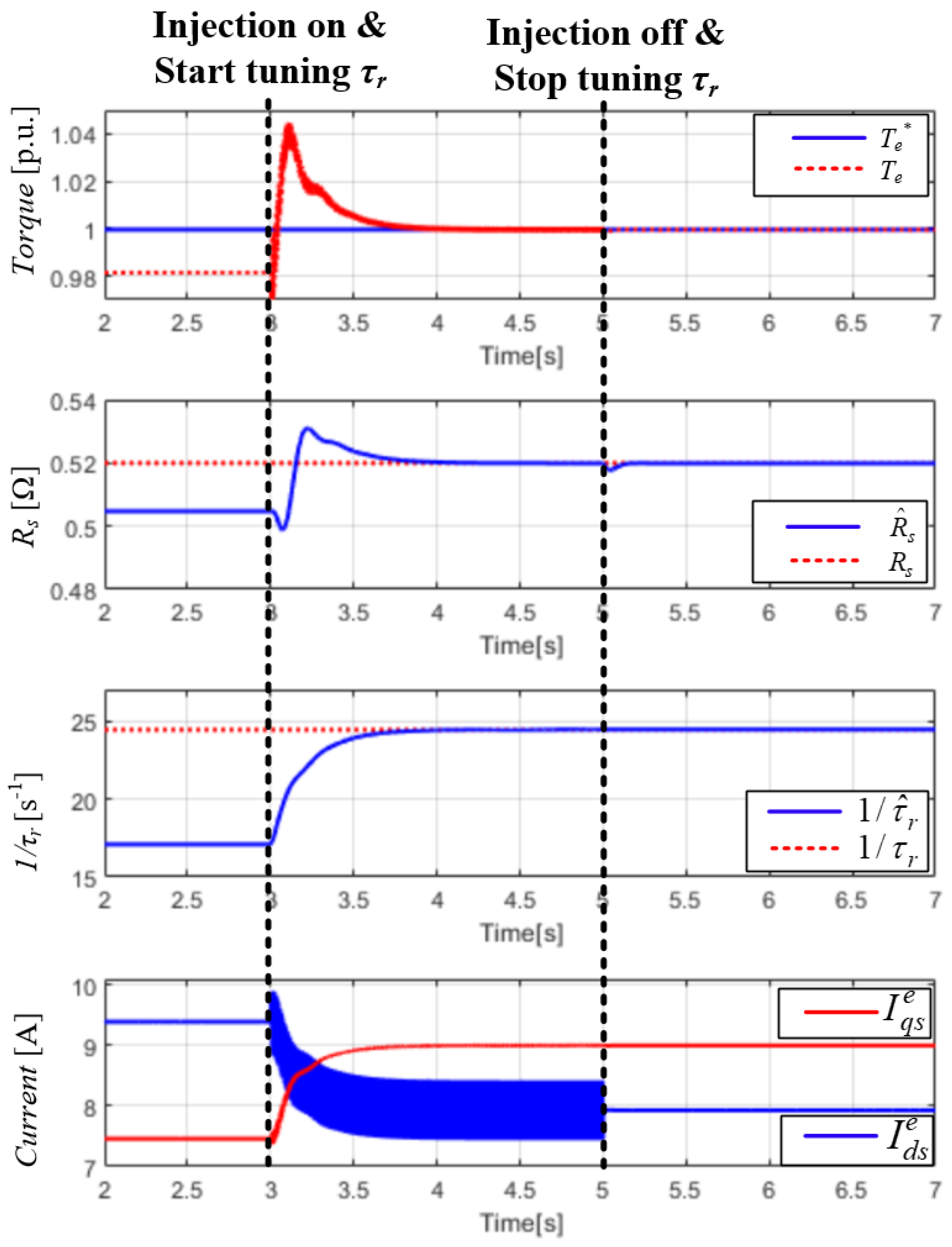
Figure 14 illustrates the performance of the proposed method for online tuning of the rotor time constant. The operation speed and torque reference were set to 0.1 p.u., and a 30% error was considered for the rotor time constant. In the initial state, only MRAS-based Rs estimation was performed. The rotor time constant error produced errors in both the estimated Rs and torque. However, once the high-frequency current was injected, the rotor time constant could be tuned, whereby the Rs estimation error was eliminated. The compensated values converged within 2 s. Then, the injection of the high-frequency current was ceased, along with rotor time constant compensation. Even after the injection of the high-frequency current, error-free Rs estimation and torque control could be maintained because of the tuning of the rotor time constant.
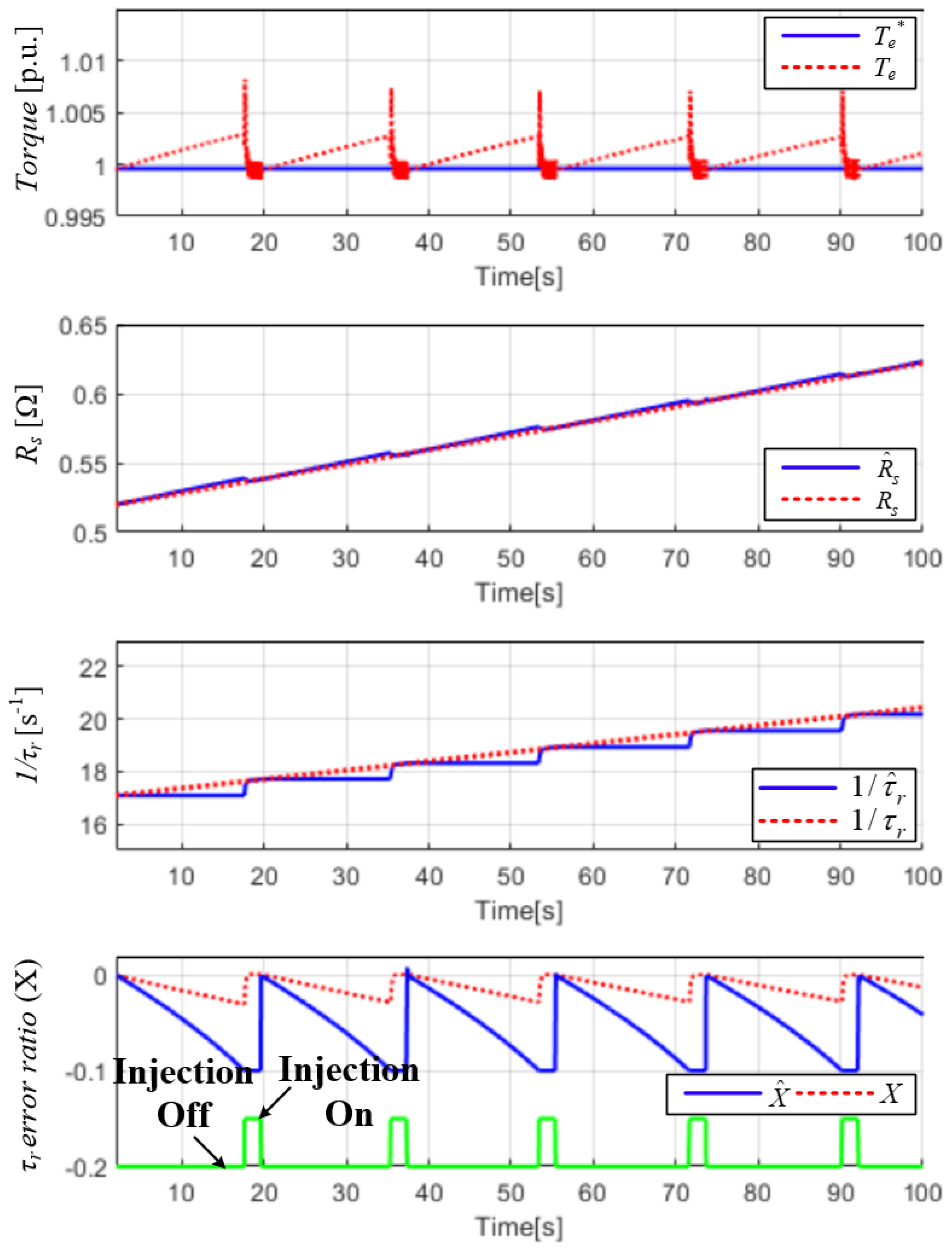
Figure 15 presents the results of applying the proposed control method (Figure 10). The stator and rotor resistances were linearly increased by 20% over 100 s to resemble a variation in resistance due to thermal drift. The threshold for initiating the injection of the high-frequency current was set to 10% (i.e., Xb = 0.1), and the operation speed and torque were set to 0.1 p.u. As both resistances increased, the rotor time constant error ratio (X) and its estimate ( X ^ ) decreased; however, X ^ varied more than X because Equation (20) disregards any error in the stator resistance. As shown in Figure 15, even when MRAS-based Rs estimation was continuously performed, an error between Rs and R ^ s persisted because the rotor resistance also varied. Additionally, owing to the low-speed (0.1 p.u.) operation, X ^ varied with the stator resistance error because the copper loss due to the stator resistance affected the active power more than the torque error due to the rotor time constant error did. Importantly, because the overall temperature of the motor changed similarly, X varied within Xb, which indicates that the error of the rotor time constant could be kept within Xb. When X ^ reached Xb, the proposed strategy of rotor time constant compensation based on high-frequency current injection was applied; this enabled error-free tuning of both the stator resistance and rotor time constant, which consequently eliminated the torque error as well. The injection of the high-frequency current and the corresponding corrections to both variables were performed for 2 s. Subsequently, after all the estimates had converged, Rs_set and τr_set were updated for the next high-frequency current injection mode. To observe the functioning of the proposed online tuning method clearly, frequent injection of the high-frequency current was triggered by exaggerating the variations in both resistances. However, in an actual IM system, the resistance variation is far less severe than that in our evaluation. This confirms that the proposed online detection and tuning strategies can greatly improve the torque control performance of real-world IFOC through occasional injection of the high-frequency current.

6. Conclusions

This paper proposes a method for online compensation of the rotor time constant in IM IFOC. This method only uses the torque–current table that is typically required for accurate torque control. Conventional MRAS-based compensation strategies directly compensate for the rotor time constant. For instance, in a reactive-power-based MRAS, the rotor time constant is compensated for by comparing the reference reactive power with the adaptive reactive power, for which the current-dependent inductance map is essential. In contrast, the proposed method first estimates the stator resistance, from which the error component of the rotor time constant is derived. When this error exceeds a certain threshold, a high-frequency current is injected to compensate for the rotor time constant. During this process, a synchronous stator flux estimator is employed to estimate the torque without any delay or decay, which enables the rotor time constant to be corrected based on the estimated torque. The high-frequency current is not continuously injected throughout the motor operation. Instead, injection is triggered only when the ratio of the rotor time constant estimation error surpasses the threshold. By injecting the high-frequency current, rotor time constant compensation is achieved with the requirement for any other parameter. Partial and full simulations conducted under various speed and load conditions confirmed the effectiveness of the proposed method.
When high-frequency current injection is enabled, the proposed rotor time constant estimator achieves performance largely independent of machine-parameter uncertainties, offering clear advantages over conventional rotor time constant estimators. Nevertheless, high-frequency injection can limit applicability in some applications and may be constrained at high speeds due to reduced voltage headroom. On the other hand, the method can be combined with high-frequency signal injection sensorless control, and it can be extended to motor-temperature estimation through stator resistance identification.

Funding

This research received no external funding.

Data Availability Statement

The original contributions presented in this study are included in the article. Further inquiries can be directed to the corresponding author.

Conflicts of Interest

The author declares no conflicts of interest.

Abbreviations

The following abbreviations are used in this manuscript:
IFOCIndirect field-oriented vector control
IMInduction machine
MRASModel reference adaptive system
PIProportional–integral

References

  1. Mastorocostas, C.; Kioskeridis, I.; Margaris, N. Thermal and slip effects on rotor time constant in vector controlled induction motor drives. IEEE Trans. Power Electron. 2006, 21, 495–504. [Google Scholar] [CrossRef]
  2. Wade, S.; Dunnigan, W.; Williams, B.W. A new method of rotor resistance estimation for vector-controlled induction machines. IEEE Trans. Ind. Electron. 1997, 44, 247–257. [Google Scholar] [CrossRef]
  3. Ba-Razzouk, A.; Cheriti, A.; Sicard, P. Implementation of a DSP based real-time estimator of induction motors rotor time constant. IEEE Trans. Power Electron. 2002, 17, 534–542. [Google Scholar] [CrossRef]
  4. Wang, C.; Novotny, D.W.; Lipo, T.A. An automated rotor time-constant measurement system for indirect field-oriented drives. IEEE Trans. Ind. Appl. 1998, 24, 151–159. [Google Scholar] [CrossRef]
  5. Telford, D.; Dunnigan, M.W.; Williams, B.W. Online identification of induction machine electrical parameters for vector control loop tuning. IEEE Trans. Ind. Electron. 2003, 50, 253–261. [Google Scholar] [CrossRef]
  6. Chen, J.; Huang, J. Stable simultaneous stator and rotor resistances identification for speed sensorless IM drives: Review and new results. IEEE Trans. Power Electron. 2018, 33, 8695–8709. [Google Scholar] [CrossRef]
  7. Buchholz, O.; Bocker, J.; Bonifacio, J. Online-identification of the Induction Machine Parameters using the Extended Kalman Filter. In Proceedings of the 2018 XIII International Conference on Electrical Machines (ICEM), Alexandroupoli, Greece, 3–6 September 2018. [Google Scholar]
  8. Wang, K.; Chen, B.; Shen, G.; Yao, W.; Lee, K.; Lu, Z. Online updating of rotor time constant based on combined voltage and current mode flux observer for speed-sensorless AC drives. IEEE Trans. Ind. Electron. 2014, 61, 4583–4593. [Google Scholar] [CrossRef]
  9. Gadoue, S.M.; Giaouris, D.; Finch, J.W. MRAS sensorless vector control of an induction motor using new sliding-mode and fuzzy-logic adaptation mechanisms. IEEE Trans. Energy Convers. 2010, 25, 394–402. [Google Scholar] [CrossRef]
  10. Toliyat, H.A.; Arefeen, M.S.; Rahman, K.M.; Figoli, D. Rotor time constant updating scheme for a rotor flux-oriented induction motor drive. IEEE Trans. Power Electron. 1999, 14, 850–857. [Google Scholar] [CrossRef]
  11. Sul, S.-K. Control of Electric Machine Drive Systems, 3rd ed.; John Wiley & Sons: Hoboken, NJ, USA, 2011; pp. 201–213. [Google Scholar]
  12. Cao, P.; Zhang, X.; Yang, S. A unified-model-based analysis of MRAS for online rotor time constant estimation in an induction motor drive. IEEE Trans. Ind. Electron. 2017, 64, 4361–4371. [Google Scholar] [CrossRef]
  13. Zhang, X.; Zhang, Y.; Yang, S.; Xie, Z.; Cao, P. An improved MRAS for rotor time constant updating in induction motor drives utilizing dot product of stator current and rotor flux. IEEE Trans. Power Electron. 2019, 34, 8905–8915. [Google Scholar] [CrossRef]
  14. Maiti, S.; Chakraborty, C.; Hori, Y.; Ta, M.C. Model reference adaptive controller-based rotor resistance and speed estimation techniques for vector controlled induction motor drive utilizing reactive power. IEEE Trans. Ind. Electron. 2008, 55, 594–601. [Google Scholar] [CrossRef]
  15. Cao, P.; Zhang, X.; Yang, S.; Xie, Z.; Zhang, Y. Reactive-power-based MRAS for online rotor time constant estimation in induction motor drives. IEEE Trans. Power Electron. 2018, 33, 10835–10845. [Google Scholar] [CrossRef]
  16. Yoo, A. Robust on-line rotor time constant estimation for induction machines. J. Power Electron. 2014, 14, 1000–1007. [Google Scholar] [CrossRef]
  17. Fot, S.; Testa, A.; De Caro, S.; Scimone, T.; Scelba, G.; Scarcella, G. Rotor Time Constant Identification on Sensorless Induction Motor Drives by Low Frequency Signal Injection. In Proceedings of the 2018 IEEE 9th International Symposium on Sensorless Control for Electrical Drives (SLED), Helsinki, Finland, 13–14 September 2018. [Google Scholar]
  18. Foti, S.; Testa, A.; De Caro, S.; Scimone, T.; Pulvirenti, M. Rotor flux position correction and parameters estimation on sensorless multiple induction motors drives. IEEE Trans. Ind. Appl. 2019, 55, 3759–3769. [Google Scholar] [CrossRef]
  19. Wang, K.; Lorenz, R.D.; Baloch, N.A. Enhanced methodology for injection-based real-time parameter estimation to improve back EMF self-sensing in induction machine deadbeat-direct torque and flux control drives. IEEE Trans. Ind. Appl. 2018, 54, 6071–6080. [Google Scholar] [CrossRef]
  20. Stankovic, A.V.; Benedict, E.L.; John, V.; Lipo, T.A. A novel method for measuring induction machine magnetizing inductance. IEEE Trans. Ind. Appl. 2003, 39, 1257–1263. [Google Scholar] [CrossRef]
  21. Noguchi, T.; Omura, T.; Hiraishi, D. Direct Field-Oriented Control of Induction Motor with Iron-Core Loss Compensation and Robust Parameter Identification. In Proceedings of the IECON’01 Annual Conference of the IEEE Industrial Electronics Society (Cat. No. 37243), Denver, CO, USA, 29 November–2 December 2001. [Google Scholar]
  22. Stojić, D.; Milinković, M.; Veinović, S.; Klasnić, I. Improved stator flux estimator for speed sensorless induction motor drives. IEEE Trans. Power Electron. 2015, 30, 2363–2371. [Google Scholar] [CrossRef]
  23. Han, Y.; Kim, H.; Kim, H.; Lee, K. Dual MRAS for robust rotor time constant compensation in IFOC IM drives. IEEE Trans. Energy Convers. 2024, 39, 1983–1993. [Google Scholar] [CrossRef]
  24. Zhang, J.; Zhang, X.; Yu, Y.; Wang, B.; Xu, D. A Model Reference Adaptive System-Based Online Rotor Time Constant Estimation Method for Induction Motor Field-Weakening Control Utilizing Dot Product of Stator Voltage and Stator Current. IEEE Trans. Transp. Electrif. 2024, 10, 3576–3589. [Google Scholar] [CrossRef]
  25. Ray, N.; Das, D.; Goswami, G. Active Power Based MRAS for Estimation of Inverse Rotor Time Constant in Field-Oriented Control of Induction Motor Drive. IEEE Trans. Ind. Appl. early access. 2025. [Google Scholar] [CrossRef]
  26. Reddy, G.; Poddar, G.; Muni, B. Parameter Estimation and Online Adaptation of Rotor Time Constant for Induction Motor Drive. IEEE Trans. Ind. Appl. 2024, 58, 1416–1428. [Google Scholar] [CrossRef]
  27. Teodorescu, R.; Blaabjerg, F.; Borup, U.; Liserre, M. A New Control Structure for Grid-Connected LCL PV Inverters with Zero Steady-State Error and Selective Harmonic Compensation. In Proceedings of the Nineteenth Annual IEEE Applied Power Electronics Conference and Exposition, APEC ‘04, Anaheim, CA, USA, 22–26 February 2004. [Google Scholar]
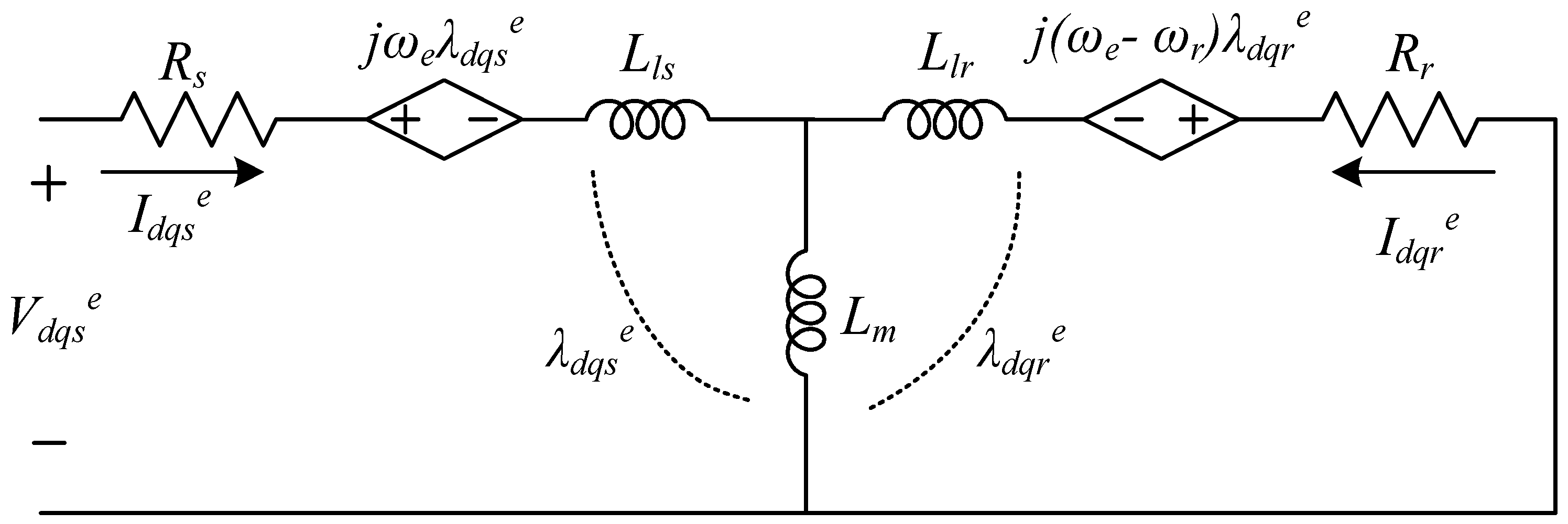
Figure 1. dq equivalent circuit of IM in synchronous reference frame.
Symmetry 17 01729 g001
Figure 2. Block diagram of conventional IFOC.
Symmetry 17 01729 g002
Figure 3. Real and approximated torques according to rotor time constant.
Symmetry 17 01729 g003
Figure 4. Current vectors with respect to real and estimated rotor flux reference frames.
Symmetry 17 01729 g004
Figure 5. Block diagram of resonant controller for the injected high-frequency current.
Symmetry 17 01729 g005
Figure 6. Block diagram for generating compensation term for rotor time constant from estimated torque.
Symmetry 17 01729 g006
Figure 7. Stator flux and torque estimated using Equation (28) and existing method [23].
Symmetry 17 01729 g007
Figure 8. Block diagram of synchronous stator flux estimator with BPF and active damping resistor [23].
Symmetry 17 01729 g008
Figure 9. Stator flux and torque estimated using synchronous stator flux estimator with BPF A-damping [23].
Symmetry 17 01729 g009
Figure 10. Flowchart of proposed online tuning method for rotor time constant.
Symmetry 17 01729 g010
Figure 11. Block diagram of proposed online tuning method for rotor time constant in IFOC.
Symmetry 17 01729 g011
Figure 12. Accuracy of detecting rotor time constant variation based on Rs estimation at ωrpm values of (a) 0.1 and (b) 1 p.u.
Symmetry 17 01729 g012
Figure 13. Processed torque ripple with respect to rotor time constant at ωrpm = 0.1 p.u.
Symmetry 17 01729 g013
Figure 14. Online tuning performance of proposed high-frequency current injection and MRAS-based R estimation method at ωrpm = 0.1 p.u.
Symmetry 17 01729 g014
Figure 15. Online rotor time constant compensation using proposed online detection and tuning strategies.
Symmetry 17 01729 g015
Table 1. Required parameters for different MRAS models.
MRAS ModelReference ModelAdaptive ModelRequired Parameters
Dot product of stator current and rotor flux [13] λ d s s I d s s + λ q s s I q s s L m I d s e ^ 2 R s , τ r , σ L s , L m , L r L m
Active power [12] V d s e ^ I d s e ^ + V q s e ^ I q s e ^ R s I d s e ^ 2 + I q s e ^ 2 + L m 2 L r ω e I d s e ^ I q s e ^ R s , τ r , L m 2 L r
Reactive power [12] V q s e ^ I d s e ^ V d s e ^ I q s e ^ L m 2 L r σ L s ω e I d s e ^ 2 + σ L s ω e I q s e ^ 2 τ r , L m 2 L r , σ L s
Table 2. IM parameters and inverter conditions.
ParameterValue
Pole pairs3
Base speed1000 r/min
Stator resistance (Rs)0.52 Ω
Rotor resistance (Rr)0.734 Ω
Mutual inductance (Lm)37.82 mH
Stator leakage inductance (Lls)2.3 mH
Rotor leakage inductance (Llr)5.128 mH
Rated stator current12 A
Rated rotor flux0.3 Wb
Rated torque10.7 N∙m
Inverter DC link voltage250 V
Inverter switching frequency10 kHz
Disclaimer/Publisher’s Note: The statements, opinions and data contained in all publications are solely those of the individual author(s) and contributor(s) and not of MDPI and/or the editor(s). MDPI and/or the editor(s) disclaim responsibility for any injury to people or property resulting from any ideas, methods, instructions or products referred to in the content.