1. Introduction
The 115 V/400 Hz AC power supply is crucial in aviation ground power and distribution systems. However, the diverse power load and aviation energy storage equipment can cause variability, leading to imbalance and distortion in the inverter output voltage. This not only affects system stability and reliability but also disrupts the symmetry of the power supply. Typically, a DC 700 V source is transformed into a high-frequency inverter voltage through an inverter circuit. The desired 115 V/400 Hz sine wave with constant voltage and frequency is achieved using a transformer with a specific transformation ratio [
1,
2]. However, the diverse power load and aviation energy storage equipment introduce variability that directly impacts inverter output characteristics. This variability can lead to imbalance and distortion in the inverter output voltage, affecting system stability and reliability. Consequently, studying the control strategy of the intermediate frequency inverter becomes essential [
3,
4,
5]. The choice of a passive controller significantly influences the performance of the closed-loop power supply system. While the Proportional Integral (PI) controller is simple and widely used, it struggles with error-free tracking of AC signals in the static coordinate system, resulting in steady-state errors. Addressing load imbalance, previous studies [
6,
7] implemented a double closed-loop control strategy to stabilize the bus voltage. However, this method has limitations, and an improved double-loop control strategy [
8,
9] introduces complexity and potential time delays. In light of these challenges, Linear Auto Disturbance Rejection Control (LADRC) emerges as a promising alternative. LADRC, a new control method post-PID control, exhibits robustness in the face of changing parameters and uncertainties, making it suitable for dynamic systems [
10]. Applying LADRC in a double closed-loop control system enhances robustness and rapidity [
11,
12].
Existing research explores internal model control strategies such as premixed compression ignition (PCI) control [
13], repetitive control (RC) [
14], and PR control [
15]. Quasi-Proportional Resonance (QPR) has been introduced to track the fundamental signal and suppress negative sequence components [
16,
17,
18], contributing to a balanced three-phase output voltage. To address filter inductance fluctuations that degrade RC stability, the authors of [
19] proposed a self-tuning RC combined with active damping, dynamically adjusting damping ratios and phase-lead compensation to maintain total harmonic distortion (THD) < 1.5% under overloads while enhancing the phase margin by 25%. The authors of [
20] propose a series low-pass filter in the internal mode of repetitive control to reduce high-frequency gain and suppress resonance peaks, while another approach [
21] combines PI control and RC in parallel to enhance steady-state and dynamic performance for grid-connected systems.
Furthermore, hybrid control was advanced by integrating LADRC, PI + RC, and QPR in a bipolar architecture, decoupling positive (d-q frame) and negative (α-β frame) sequence regulation to achieve a 52.7% THD reduction under single-phase unbalance and a 30% faster transient response (50 ms settling time) [
22]. On the modulation front, a 3D-Space Vector Modulation (3D-SVM) was developed for three single-phase combined inverters, expanding switching states to 27 and achieving 15% higher voltage utilization and a 22% THD reduction compared to SPWM [
23], critical for modular ground power units (GPUs). A multi-port indirect matrix converter topology was also pioneered for aviation power supplies, eliminating intermediate DC links to enable efficient AC–AC conversion and aligning with “green airport” sustainability goals [
24].
These advancements highlight the potential of integrated control, adaptive modulation, and novel typologies, yet challenges remain: (1) the limited robustness of existing RC/QPR to extreme filter parameter variations, (2) the high computational overhead of traditional double d-q transformations, and (3) a lack of seamless integration between adaptive control and modular hardware. A comparison of previously reported works is summarized in
Table 1.
In response to these findings, this paper presents an improved bipolar coordinate control strategy, which not only minimizes the steady-state error in tracking AC signals but also effectively suppresses negative sequence components due to load imbalance. This strategy contributes to enhancing the symmetry of the power output, a crucial aspect of power systems. LADRC control replaces PI control in the positive sequence component voltage loop to enhance system robustness. The current loop of the positive sequence component adopts PI + RC compound control to eliminate periodic disturbances and reduce harmonic content in the common rotating coordinate system. In the two-phase static coordinate system, a QPR controller adjusts the negative sequence component, achieving zero static error tracking of AC signals and minimizing harmonic content during power system imbalances. The proposed control strategy’s performance and current harmonic content are compared with a common double rotation coordinate control system in MATLAB R2022a simulations, validating its effectiveness.
2. Modeling and Control Strategy of Inverter
The basic topology of the variable frequency inverter is shown in
Figure 1. In order to simplify the model, it is assumed that the power supply is the direct current source, the IGBT is an ideal device, and a series of parameters such as the IGBT on/off time are ignored.
are respectively six IGBT. a,b,c are respectively node between
and
, node between
and
, and node between
and
. The filter is an ideal LC filter, and internal voltage drop and loss of all components in the topology are ignored, and the influence between devices is ignored.
represents the filter inductor,
represents the internal resistance of the filter inductor,
represents the filter capacitor,
represents the input, and
,
, and
are the three-phase load, respectively.
,
, and
are the three-phase inductance current, respectively,
,
, and
are three-phase filter current, respectively, and
,
, and
are the three-phase load current, respectively.
According to
Figure 1 and KVL, the mathematical model of the inverter can be expressed as follows:
According to the three-phase balance and the principle of power conservation, the transformation relationship from three-phase static coordinates to two-phase synchronous rotating coordinates is expressed as follows:
According to Equations (1) and (2), the equations of voltage and current in the d-q rotating coordinate system can be obtained by the Laplace transformation.
where
is the fundamental angular frequency,
and
are the filter capacitor voltage, respectively,
and
are the output voltages of the inverter, respectively, and
and
are the inductor currents, respectively.
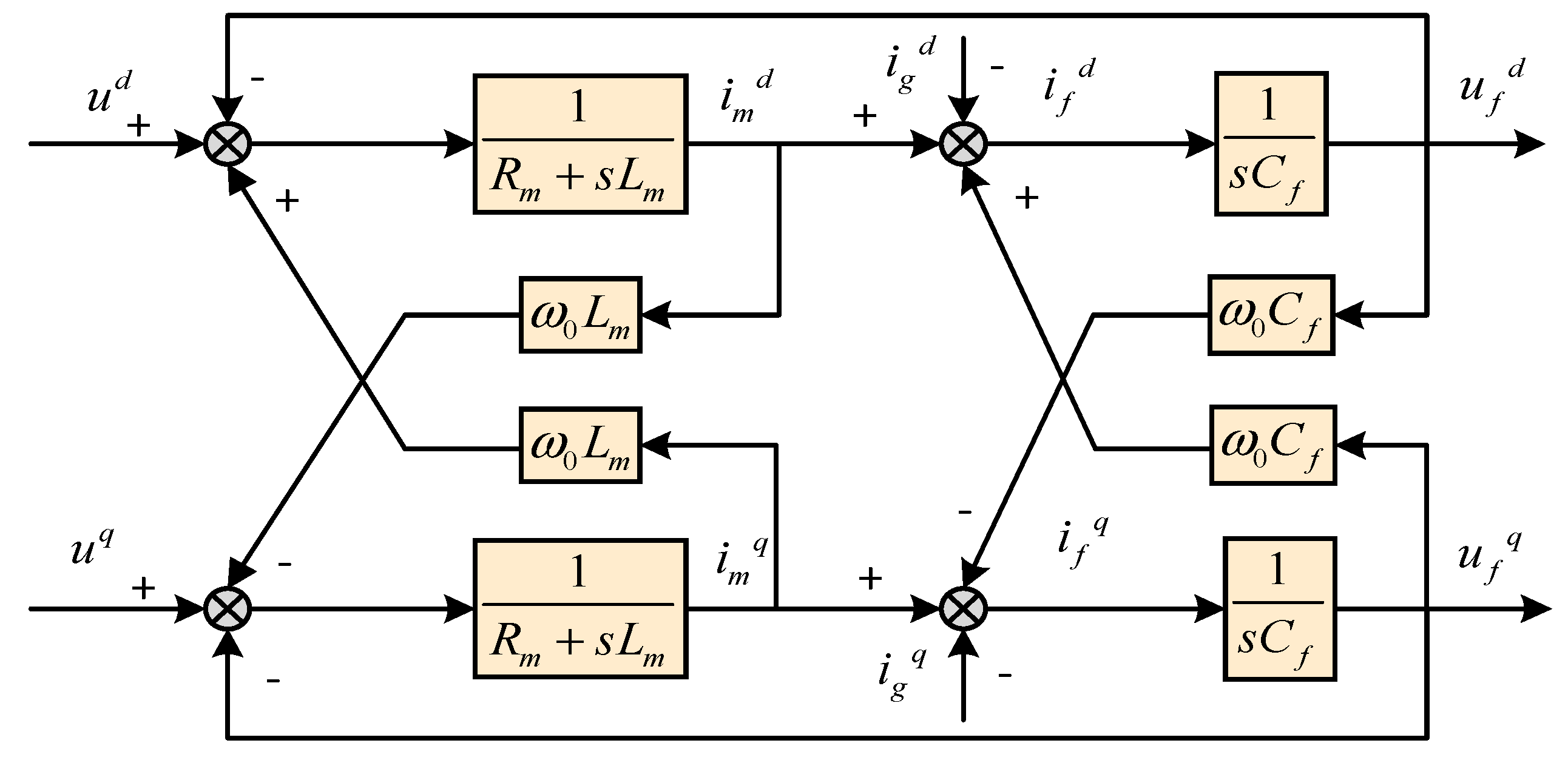
Based on the above analysis and according to Equations (3) and (4), the equivalent block diagram of the model of the inverter system under the two-phase synchronous rotating coordinate system is obtained in
Figure 2.
From Equations (3) and (4), it can be seen that the rotation transformation introduces coupling between the d-axis and q-axis of the system, and the currents and are not only controlled by the control quantities and ; they are also affected by the inductive coupling voltages and and capacitor voltages and . Similarly, the output voltages and of the d-q axis of the system are not only controlled by the output inductance currents and , but they are also affected by the disturbance of the coupling currents and and the load currents and .
According to the above analysis, it is necessary to add the corresponding feedforward in the loops of voltage and current to eliminate the influence of disturbance on the output. Equation (5) is the current equation in the d-q rotation coordinate system.
The capacitor voltages
and
are, respectively, introduced into the inner loop of the inductance current to compensate the inductance currents
and
. The control equations of
and
can be written as follows:
where
and
, respectively, represent the reference values of the current inner loop;
and
, respectively, represent the proportional coefficient and integral coefficient of the current inner loop PI control, respectively.
It can be seen from Equation (6) that the target current required in the d-q rotating coordinate system can be generated as long as the proportional coefficient and integral coefficient in the PI control are adjusted. The voltage equation in the d-q rotation coordinate system can be obtained as follows:
Similarly, it can be concluded that
and
and
and
are introduced into the voltage loop as feedforward to compensate the output current, and the feedforward decoupling equation of the currents
and
through the inductor can be obtained as follows:
where
and
, respectively, represent the reference values of the d-q axis of the voltage loop;
and
represent the proportional coefficient and integral coefficient of the voltage loop PI, respectively. It can be seen from Equation (8) that the target voltage required in the d-q rotating coordinate system can be generated as long as the proportional coefficient and integral coefficient in the PI control are adjusted.
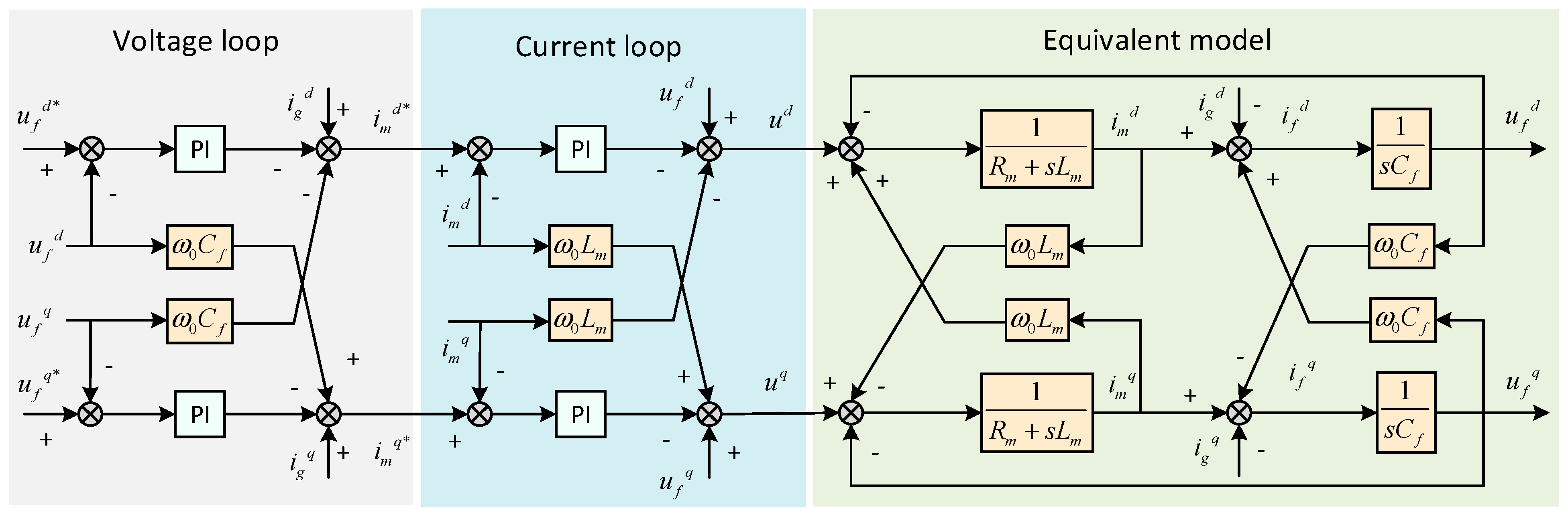
By accurately adjusting the coefficients of the current loop and voltage loop, the system can maintain a more symmetric distribution of currents in the d-q axes, which is essential for ensuring the symmetry of power output and the stability of the overall system. According to the above analysis, the overall control structure of the double-loop decoupling control of the three-phase inverter can be expressed as shown in
Figure 3.
3. Double Rotating Coordinate System Control Based on the Separation of Positive and Negative Sequence
When the fundamental voltage is only considered and the three-phase output voltage is unbalanced, the zero sequence component can be ignored in the three-phase three-wire system. The three-phase unbalanced quantities can be expressed as follows:
where
and
are the peak values of the fundamental voltages of the positive and negative sequence components, respectively;
is the phase of the negative sequence component;
is the angular frequency.
The three-phase voltage transformed to the two-phase
static coordinate system can be expressed as follows:
where
,
,
, and
are the components of the positive and negative sequence components in the
coordinate system.
According to Equation (9), the positive sequence component can be written as follows:
Therefore, the composite vector of the positive sequence components in the three-phase coordinate system is
where
is the angle between the synthetic vector
and a-axis;
is the phase angle of the d-q coordinate system for the three-phase coordinate system when the synthetic vector
is transformed into the d-q coordinate system.
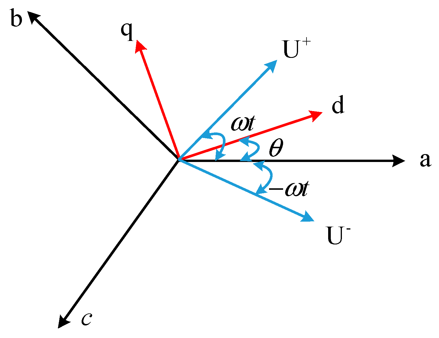
As shown in
Figure 4, when
, the component of synthetic vector on the q-axis is zero. If there is a negative sequence component in the system with an unbalanced three-phase load, the synthetic vector
in the negative sequence component rotates clockwise with respect to the d-q coordinate system according to the angular frequency
. Therefore, the transformation to the q-axis is equivalent to the addition of the AC component of
in
.
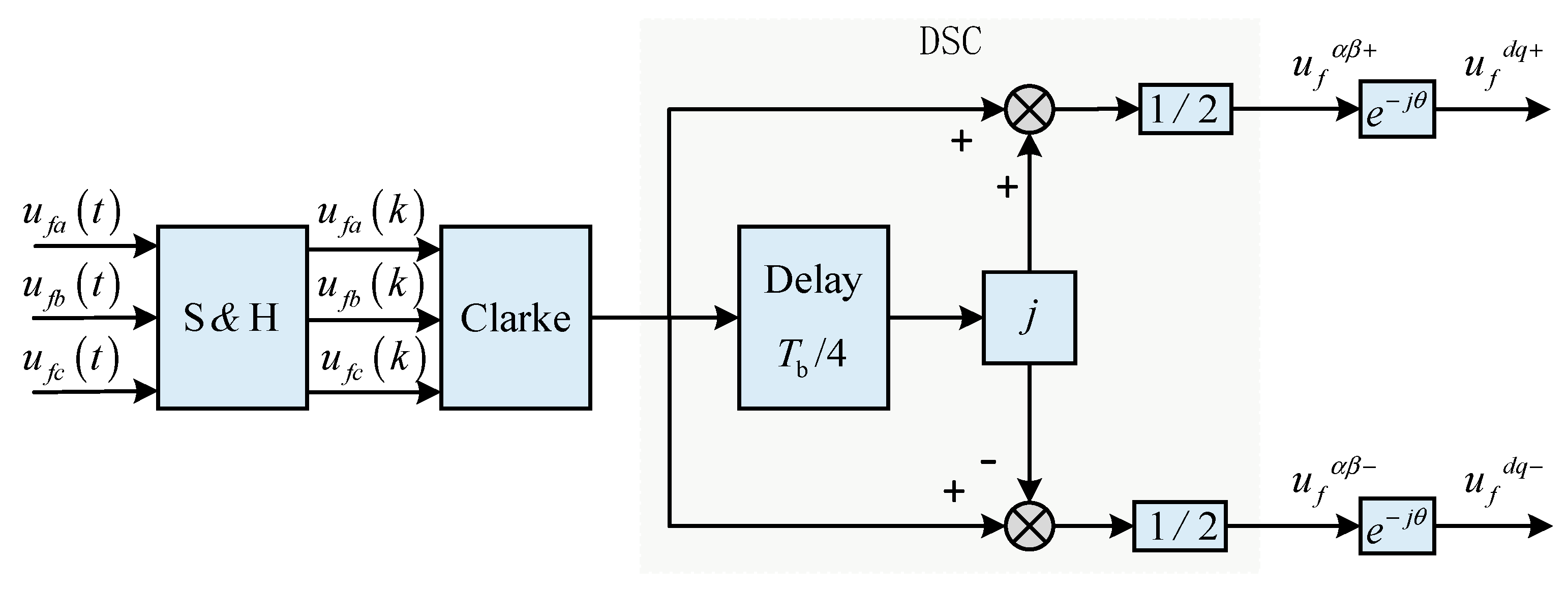
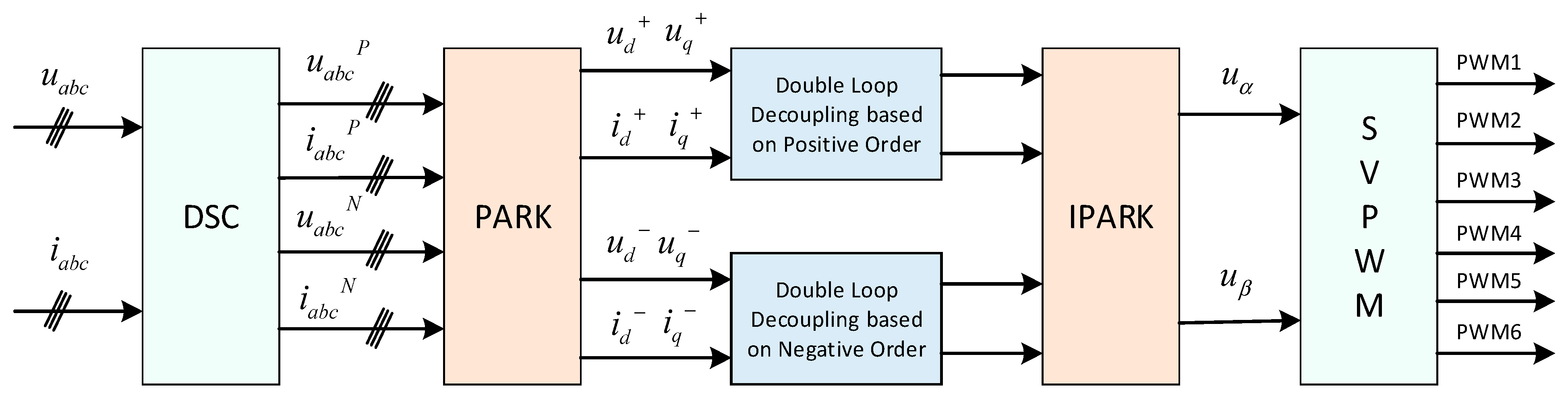
When detecting the output unbalanced voltage, this paper adopts the delay signal cancellation (DSC) technology to separate the positive and negative sequence components. The choice of delay signal cancellation (DSC) for positive/negative sequence separation in this study is motivated by its distinct advantages over alternative techniques like the Second-Order Generalized Integrator (SOGI), particularly tailored to the requirements of aviation 400 Hz inverter systems. The main idea of this method is to use the sinusoidal signal with a quarter of delay to superimpose the original signal, so as to construct the quadrature signal with the same amplitude as the original signal. The negative sequence component and the specific sub-harmonic signal are canceled by the operation, so as to extract the fundamental frequency voltage of the positive sequence. The principle is shown in
Figure 5, and the mathematical expression of the delay cancellation operator is
The positive and negative sequence voltages are separated by the above DSC algorithm, and the separation expression is
where,
and
are the sampling frequency and the fundamental frequency of the output voltage, respectively.
After the DSC algorithm, the positive and negative sequence components in the two-phase
static coordinate system can be separated. Then, the positive and negative sequence components of the output voltage in the two-phase
rotating coordinate system shown in Equation (15) are obtained.
The algorithm block diagram is shown in
Figure 5.
In the synchronous rotating coordinate system, the PI controller with closed-loop feedback control can output the positive sequence and negative sequence voltage without static error tracking in the integration link and can effectively suppress the fundamental disturbance of the output voltage of the inverter. Therefore, firstly, the output voltage and current of the inverter are collected, and the positive sequence component
,
and negative sequence component
,
of the output voltage and current are obtained through positive and negative sequence separation (DSC). Then, the positive sequence component
,
and negative sequence component
,
of the output voltage and current in the two-phase rotating coordinate system are obtained by a park transformation. The positive sequence and negative sequence components are, respectively, subject to double-loop feedforward decoupling control to obtain the corresponding compensation, and then the results are superimposed to obtain
,
through an inverse park transformation. The six drive signals PWM1-PWM6 of the IGBT of the three-phase inverter are adjusted by space vector pulse-width modulation control technology. The overall control diagram is shown in
Figure 6. The positive and negative sequence separation double-loop decoupling control strategy based on a double rotating coordinate system realizes zero steady-state error regulation of the positive sequence and negative sequence components of the output voltage of the three-phase inverter, thus eliminating the output voltage imbalance caused by an unbalanced load. This is essential for maintaining the symmetry of the power output.
4. Improved Bipolar Coordinate Decoupling Control Based on Positive and Negative Sequence Separation
One of the common coordinate system control algorithms is to park the AC component in the three-phase stationary coordinate system in the DC component in the two-phase rotating coordinate system. Another method is to convert the three-phase static coordinate system to the two-phase static coordinate system. Since Clark only performs matrix operations on the signal, the signal frequency will not change.
The two existing methods have their own characteristics and can complement each other. On the premise of positive and negative sequence separation, this paper proposes that the voltage loop of the positive sequence component is introduced into LADRC control, the current loop adopts PI + RC control after d-q decoupling, and then the negative sequence component is adjusted by the QPR controller in the two-phase static coordinate system.
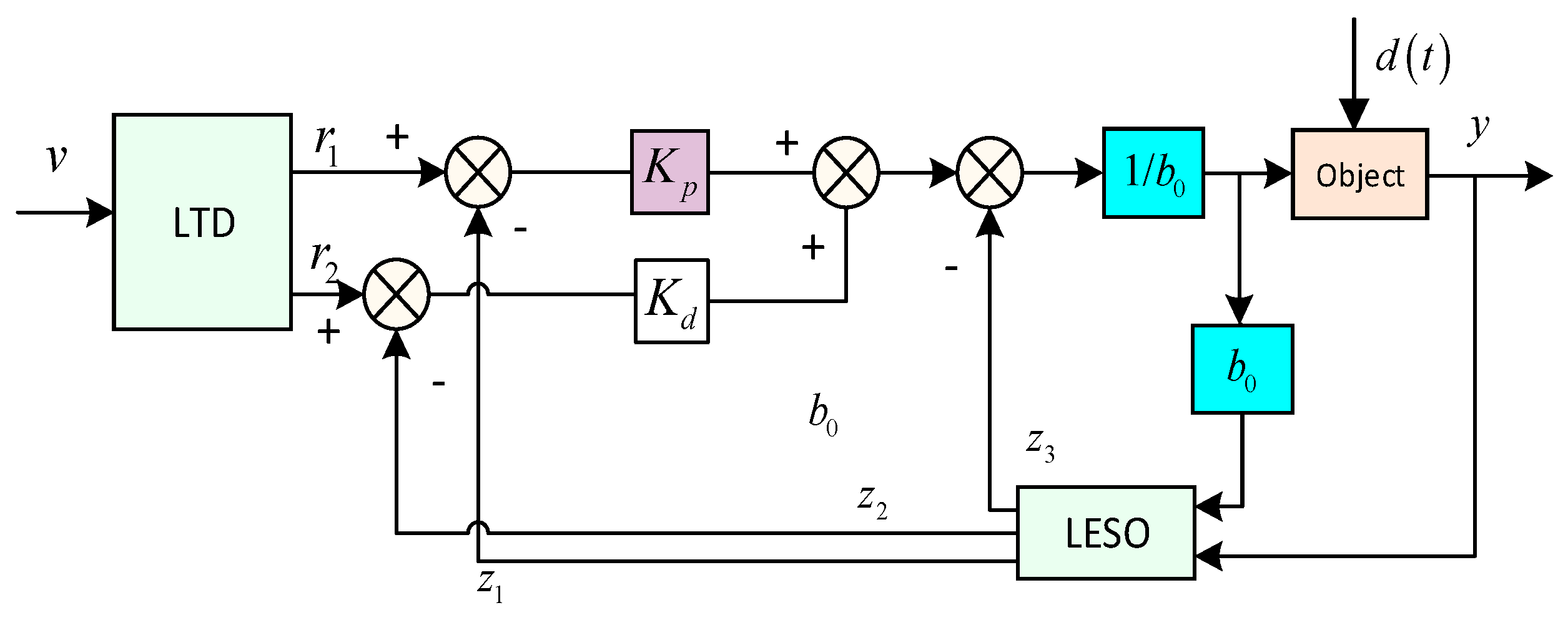
4.1. LADRC Control Principle
LADRC can be divided into linear and nonlinear and is composed of a linear tracking differentiator (LTD), linear extended state observer (LESO), and linear state error feedback control law (LSEF). The LTD can track the input signal of the system quickly without overshooting and can give a good differential signal; the LESO can estimate the state and disturbance of the system; the LSEF is used to obtain the control quantity, which is often simplified to the design of PD combination.
Figure 7 shows the structural schematic diagram of the second-order LADRC.
The corresponding LESO can be designed as follows:
where
is the estimated value of
;
is the estimated value of
;
is the estimated value of
;
are the observer gain.
The second-order LADRC can be designed as follows:
and are two signals output through the LTD, where , , and and are the controller bandwidth. The linear extended state observer gains are .
As can be seen from
Figure 7, this structure is relatively simple. It only needs to adjust
and other parameters to complete the parameter setting of ADRC.
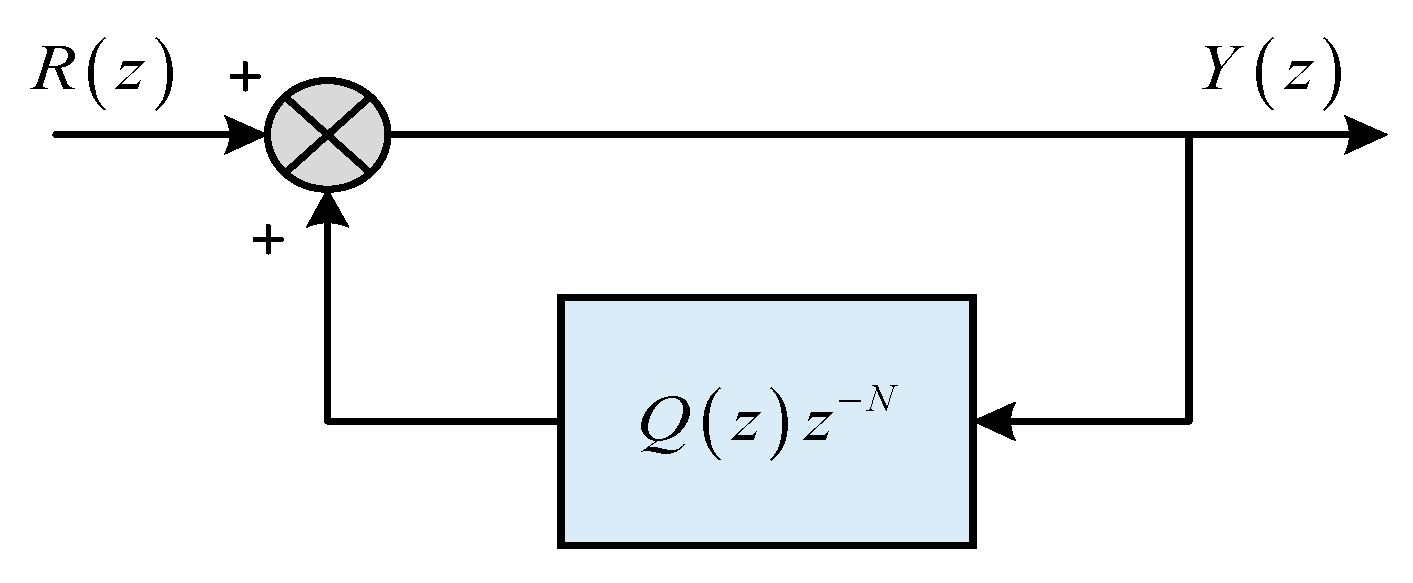
4.2. PI + RC Compound Control
Using a two-phase rotating coordinate system in a positive sequence can effectively reduce the output DC component of the inverter and reduce the harm of the DC component. Repetitive control based on the internal model principle can effectively eliminate system periodic disturbance and error and reduce harmonic content. Equation (18) is the expression of the repetitive controller. The structure of the repetitive control in the discrete domain is shown in
Figure 8.
In Equation (18), is defined as the number of sampling points per fundamental period, where (sampling frequency) and (output frequency). The theoretical value is = 10,000/400 = 250, but = 200 is chosen to reduce the computational load in embedded control hardware, as higher values increase memory usage and delay compensation complexity, and represents the internal model coefficient. In order to stabilize the internal model, is usually taken as a constant slightly less than 1 or a low-pass filter with a gain of less than 1.
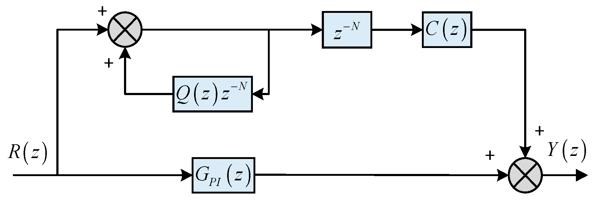
The PI controller has good dynamic and steady-state regulation performance. Repetitive control has a high suppression ability to periodically repeat disturbance signals. The combined composite controller not only improves the ability to suppress the harmonics of the inverter but also improves the dynamic response performance of the system. The controller structure is shown in
Figure 9.
In
Figure 9,
is a compensator designed for the control object, which is used to make the system have zero phase shift and zero gain in the low-frequency band and increase the high-frequency suppression capability at the same time. Generally,
,
represents the repetitive control gain, and
represents the coefficient of the phase compensation. Under the condition of sampling delay
, as described above, N can be taken as 200;
is used to compensate for the phase delay,
is usually a second-order low-pass filter, and
can be taken as 0.8. In the high-frequency band, it is necessary to introduce a second-order low-pass filter to further attenuate the amplitude. The selected cut-off frequency is generally less than one-tenth of the sampling frequency. Therefore, a low-pass filter with a cut-off frequency of 800 Hz is selected. At the same time, in order to better suppress resonance, the damping ratio should be greater than 0.707, which is taken as 1. Then the filter function is discretized as
The system gain of the closed-loop transfer function of the system in the low-frequency band is basically zero, and the phase compensation coefficient k can be set as 2, as shown in Equation (20). The designed composite controller is
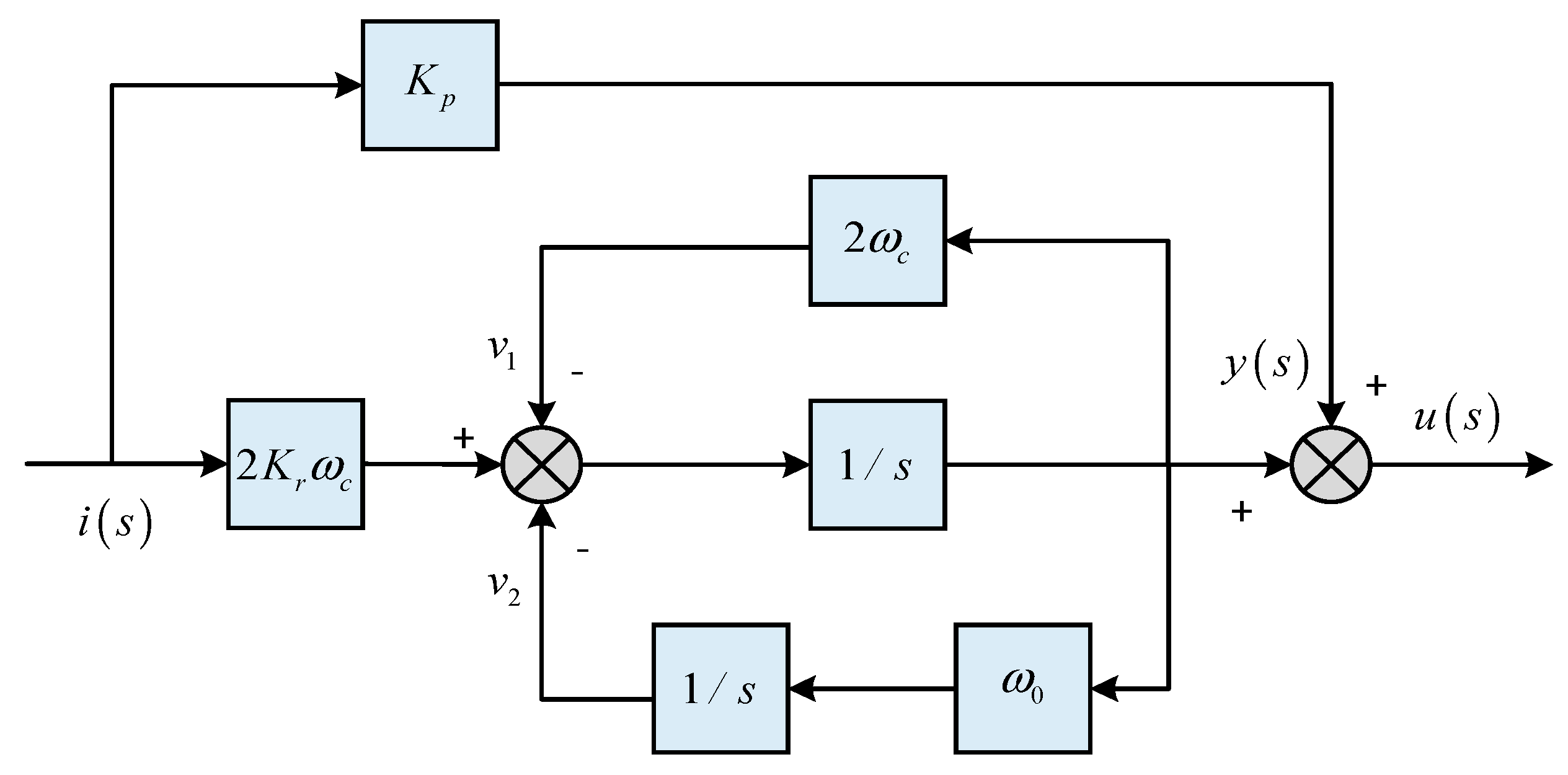
4.3. QPR Control
QPR is chosen over classic PR or SOGI variants due to its balance of simplicity, frequency robustness, and transient performance, specifically suited to the stable fundamental frequency and embedded hardware constraints of aviation 400 Hz inverters. Its design avoids the complexity of SOGI-based methods and the frequency sensitivity of classic PR, making it an optimal choice for achieving zero static error tracking of negative sequences while maintaining low computational load—key to the proposed bipolar control strategy’s effectiveness in suppressing unbalance and harmonics. The negative sequence component is regulated by a QPR controller in the two-phase stationary coordinate system. Because there is a strong coupling between the DC components of the d-q axis obtained from the Clark transform, the complexity of the control algorithm is increased. And, in the case of imbalance, some control variables will produce double frequency fluctuations. PI control can achieve no static error control for DC signals; however, steady-state errors will occur in the control process for AC signals, affecting the quality of output current. Therefore, a QPR controller is used to suppress the negative sequence components.
Compared with the common controllers of PI and PR, the QPR controller has the advantages of fast response, easy implementation, and good robustness under power grid faults. The transfer function of the QPR controller is shown in Equation (21).
where
represents the proportional coefficient;
represents the resonance coefficient;
represents the cut-off frequency;
represents the resonant frequency.
The discretization model can be written as
where
is the input quantity, corresponding to the input current deviation of the system;
is the output, corresponding to the system output reference voltage.
The schematic diagram of the QPR control algorithm is shown in
Figure 10. When the resonant frequency
is the power grid frequency, it can realize no static error tracking of the AC signal of 400 Hz and compensation of the negative sequence fluctuation signal. In addition, the gain and bandwidth at the resonant frequency can be adjusted by changing
and
and
, which will not affect the stability of the system but will improve the anti-interference performance of the system with respect to the grid frequency. The QPR controller’s proportional
and resonant
gains were obtained through a multi-step approach.
was selected based on an open-loop Bode plot analysis to ensure stability and a good dynamic response.
= 20 was determined via iterative simulations under various loads, aiming for minimal THD and good negative sequence tracking. Sampling frequency and system uncertainties were also considered.
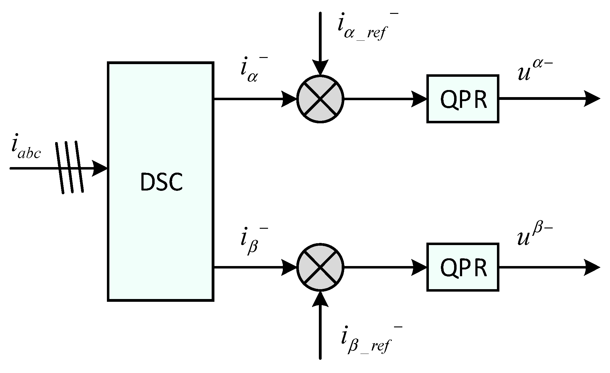
4.4. Improved Bipolar Coordinate Decoupling Control
At present, the main current control methods of inverters are direct current control and indirect current control based on a d-q rotating coordinate system. In the indirect current control, the reference signal is the voltage signal; therefore, the control variables of the d-q axis are combined with each other after the park transformation to the d-q rotating coordinate system, which increases the complexity of the control structure.
The bipolar coordinate control structure described below is proposed in this paper. The indirect current control method is adopted in the positive sequence control, and the current direct connection control method is adopted in the negative sequence control. The SVPWM modulation technology is applied to control the on/off of the power devices in the sub-module, which directly controls the output current at the AC side to achieve the purpose of compensation.
Figure 11 and
Figure 12 show positive sequence component control and negative sequence component control, respectively, which together, form the core control pole of the system.
Compared with the common double synchronous coordinate decoupling algorithm, the improved bipolar coordinate decoupling control structure proposed in this paper can effectively eliminate the periodic disturbance and error and reduce the harmonic content by using compound control in the link of positive sequence. The link of the negative sequence does not need a decoupling link, and the control algorithm is simpler and less complex. In the case of being unbalanced, the system is more stable. In addition, compared with the control method based on QPR, the method can realize the independent control of active and reactive power and improve the flexibility and pertinence of control.
The proposed bipolar control strategy simplifies negative sequence regulation and reduces computational complexity compared to the traditional double d-q coordinate system. Unlike the double d-q system—where positive and negative sequences are regulated in two independent rotating frames, requiring redundant park/inverse park transformations and complex decoupling terms—the bipolar architecture separates control into distinct coordinate frames: The positive sequence is regulated in the d-q rotating frame with LADRC/PI + RC (
Figure 11), leveraging feedforward decoupling for robust voltage/current control. The negative sequence is directly regulated in the α-β static frame with a QPR controller (
Figure 12), eliminating the need for a second d-q frame and its associated rotational decoupling terms. By independently controlling positive and negative sequences, it can better maintain the symmetry of the three-phase current amplitude under unbalanced load conditions.
6. Conclusions
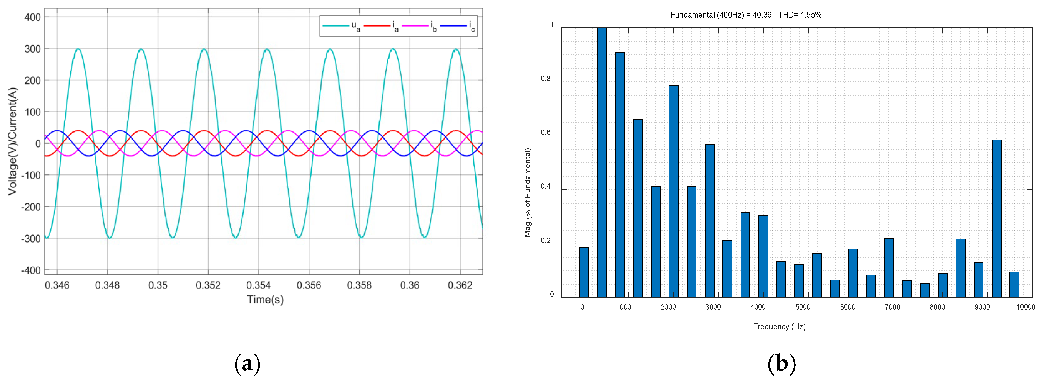
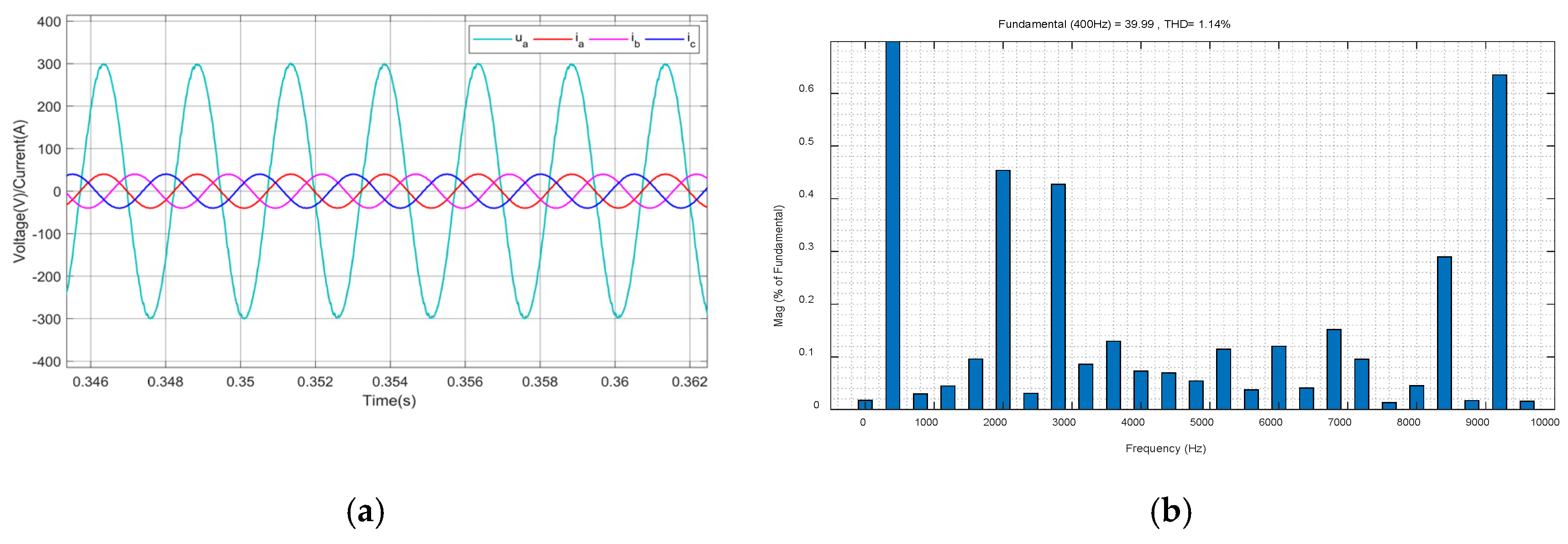
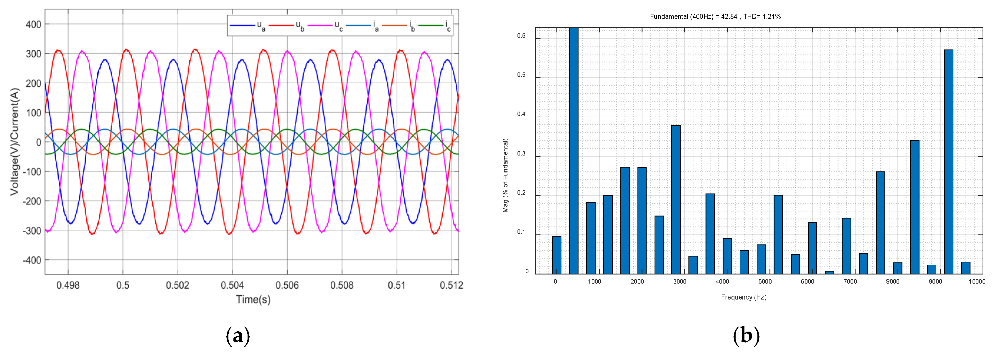
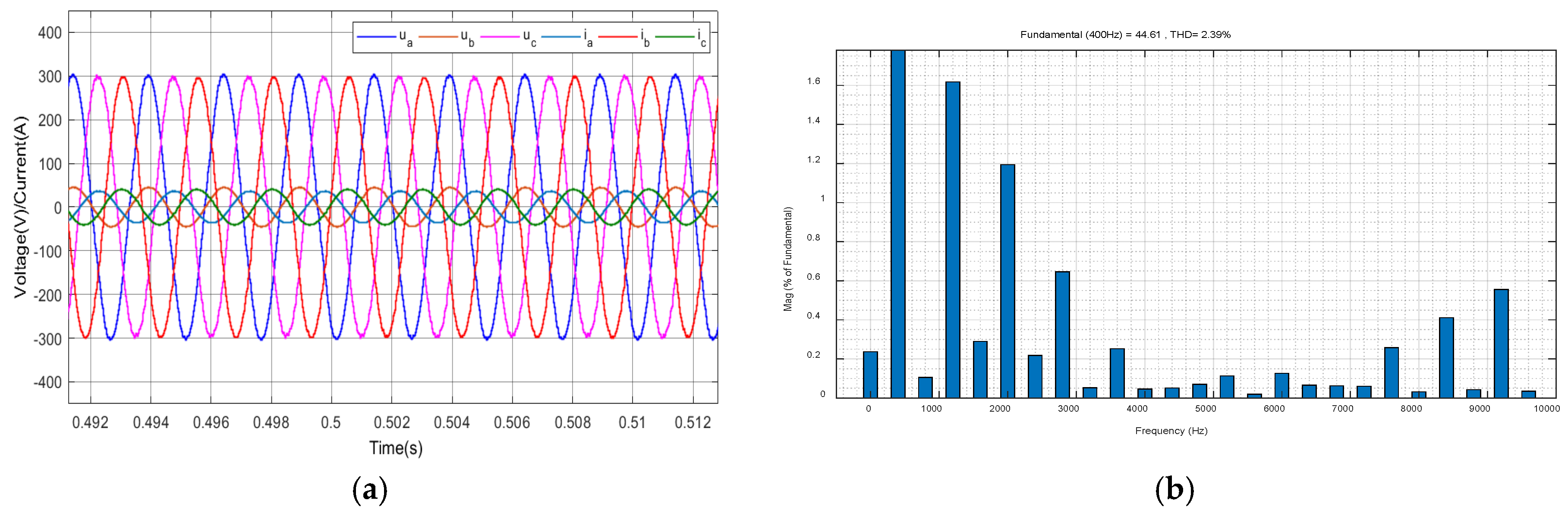
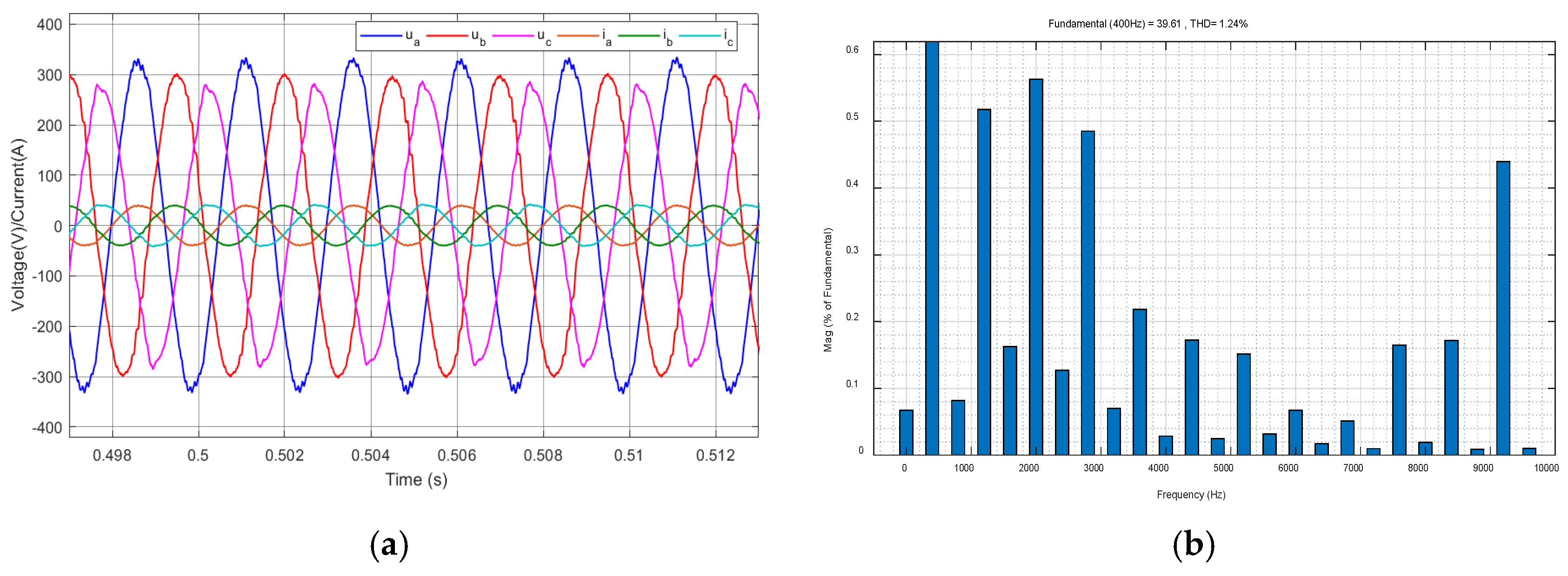
The proposed bipolar control strategy for 400 Hz inverters brings about significant improvements in power quality, dynamic response, and computational efficiency. From the perspective of symmetry, it achieves excellent harmonic suppression, which is crucial for maintaining the symmetry of the power output waveform. PI + RC reduces THD by 41.5% under balanced loads, and QPR-driven negative sequence control achieves large THD reductions for single-phase and three-phase unbalanced loads.
The proposed strategy also has a rapid transient response, with LADRC enabling 30% faster load transient recovery. This fast response helps the system quickly adapt to load changes and maintain the symmetry of the power output. However, the lack of experimental validation on hardware platforms is a limitation. Future research should focus on hardware implementation to further verify the performance of the strategy in maintaining symmetry in practical aviation ground power systems.


