1. Introduction
Due to the implementation of new technologies in many industrial plants, the efficiency of production activities has seen a continuous increase and the bottleneck has moved to the logistics area. Logistic includes a variety of processes such as: picking, packing, warehousing, inventory, delivery, and routing. In the last decade, the intelligent robot technology was extended to non-manufacturing sectors as logistic processes, and the logistic robots appeared especially for picking, packaging, palletizing and handling as a link between these operations [
1]. Another factor favouring the optimization in the logistics field is represented by the development of autonomous systems. Initially the idea transposed in automated guided vehicles (AGVs), which are systems able to move following a fixed route between some predefined points. The operation of such a system in the field of logistics results in a number of shortcomings such as increased costs of system installation, lack of flexibility of systems to a route change, fleet management, rigidity from the perspective of collaboration with other systems or the human operator [
2]. A superior technology to these AGVs is represented by autonomous mobile robots (AMRs), through which all the described disadvantages are eliminated.
The main changes are in the perception system where smart sensing solutions appeared: laser scanners, stereo vision cameras, inertial measurement unit, localization sensors and advanced processing using an additional embedded system capable of fast processing the information. AMRs can make decisions based on the perception and give to the robot an advanced mobility in a dynamic environment, which may be continuously changing. In recent years, AMRs are regular occupants in the modern logistics system, helping warehouse workers to fulfil orders with increased promptness.
The AMRs used in internal logistics contributes to improving processes by increasing productivity, reducing downtime due to lack of components and more efficient use of human resources to focus where it can bring more added value. Nowadays, AMRs is one of the fastest expanding fields of scientific research wherein academic groups and industrial companies frequently work together. AMRs attract attention more and more from the perspective of applications that have already branched off in various areas, as in search and rescue missions [
3], planetary exploration [
4], medical care [
5], intervention in extreme environments like mining [
6] and military operations [
7], agriculture [
8], household and office applications [
9], logistics and manufacturing applications [
2,
10,
11,
12], as well as other industrial and non-industrial applications.
Current logistic facilities typically represent high-traffic environments, with narrow aisles among diverse obstacles where omnidirectional mobile robots (OMRs) are a better suited solution for improved manoeuvrability.
The main contribution of the paper is a comprehensive description of a practical approach for developing an OMR system useful to those who want to extend their research from pure simulations into practical higher level applications, since the majority of the recently published research papers focus mainly on simulation results. In this regard, our study might be of interest to researchers who want to design and follow the necessary steps for the realization of the hardware in the loop (HiL) architecture using recent hardware (NVIDIA Jetson Nano, light based detection and ranging system (LiDAR), depth-camera, etc.) and software (Robot Operating System (ROS) nodes developed in MATLAB).
This paper is structured as follows:
Section 2 summarizes the related work that uses OMRs in the logistic field,
Section 3 describes the ROSY platform prototype with essential features regarding the mechanical design and the associated kinematic model, the hardware configuration, the vehicle controller firmware, followed by the description of the ROS software topology. In
Section 4, real-time motion control using ROS nodes implemented in MATLAB is detailed. Moreover, the experimental evaluation methodology is presented and the OMR position control performance is demonstrated by experimental results. Two types of scenarios are proposed: the first is related to the validation of tracking predefined trajectories and the second refers to building a map of the environment using the simultaneous localization and mapping (SLAM) algorithm with inputs from LiDAR and the robot odometry module. The platform is also tested to navigate between points defined in the map which qualified the mobile platform to be equipped with conveying system and used in logistic area. Some limitations and difficulties from experimental tests are also described. Discussions of the results and future work conclude the paper in
Section 5.
2. Related Work
Recent independent studies reflect significant research on Mecanum wheeled robots, the study [
13] compares recent research results with various OMR prototypes in the context of logistic applications, and the authors provide a review for the development of mobile robots based on Mecanum wheels which were previously used in different research centers.
Considering the issues of traditional mobile robots applications, the Mecanum wheeled platforms gain attention in different groups of researchers, and while the focus was initially on simulation results, currently it is moving towards applied, real-time, implementations. In terms of simulations, there are consistent studies for kinematic modelling [
2,
7,
14], their main focus being the controller design, which can be of different forms based on classical or advanced modern approaches [
14,
15,
16]. Moreover, path planning is also an important subject, especially in the logistic framework [
17,
18].
From the practical implementation point of view, different OMR prototypes have been designed and implemented to achieve autonomous navigation, the platforms have to obtain environment perception, localization, path planning and trajectory following abilities [
19,
20,
21,
22]. In most of the research studies, the STM32 micro-controller is the core of the low level control system, which performs various data calculations and real-time processing for different type of embedded computers [
20,
21]. The authors from [
19] proposed a low cost robot using an Arduino based system for the low level controller and Raspberry Pi as the on board computer which runs a GNU/Linux distribution. Due to the recent trends and the complexity of the tasks required for logistics applications, the currently proposed solution is deployed on a NVIDIA Jetson Nano embedded computer hosted locally on the robot, that runs the autonomous navigation software. The research presented in this paper is part of a larger project, aimed at developing an intelligent logistics system using autonomous OMRs - identified by the name ROSY-Logistic.
The main objective consists of the development of an intelligent logistics system using autonomous robot for flexible exchange of items between different fixed conveyor systems, all operations being coordinated by a warehouse management system. The ROSY platform is meant to transport materials between predefined locations in a dynamic warehouse environment by autonomously optimizing its trajectory plan in response to its surroundings. The initial steps for developing the autonomous OMRs specialised in exchanging items between conveyor systems are detailed in this study. The main purpose of the current paper is to address symmetrically the integration testing level of the V-model process by designing a HiL architecture appropriate for the technologies used in the research project, such as the integration of ROS.
3. Omnidirectional Mobile Robot in a Logistic Application
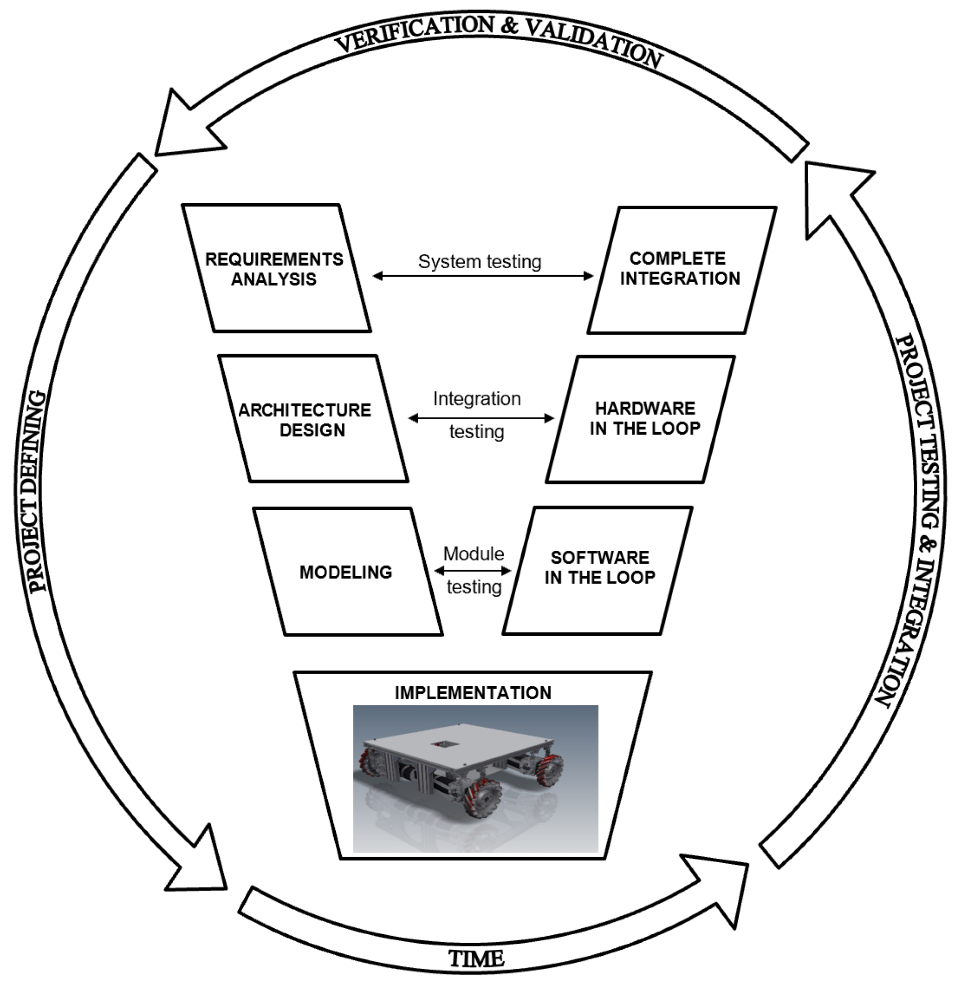
The workflow of this project follows the well-known symmetric V-model development process methodology [
23,
24] presented in
Figure 1. The approach starts on the design (left) branch by defining project requirements and goes through the lower layers to obtain an actual implementation that is verified and validated by following the symmetric testing branch that deals with module, integration and system testing, respectively.
The initial steps for developing the autonomous OMRs, specialised in exchanging items between conveyor systems are detailed in the following sections. The content of the study is addressed by the integration testing level of the V-model process through designing a HiL architecture appropriate for the proposed technology used in this research project, the ROS software package integration.
Due to the complexity of a mobile robotic structure and especially of an omnidirectional structure, in approaching the development of high-performance structures, a hierarchical leadership structure is adopted, top-down, with a strict organization, each hierarchical level being completely subordinated to the higher hierarchical level. This hierarchical approach also allows a special flexibility in the design and realization of mobile robotic structures, the changes made on a module having minimal influences on the functional structure. The control of a mobile robot can be approached either from a kinematic or from a dynamic perspective. The kinematic perspective consists in decoupling the control in two overlapping loops: the kinematic loop and the dynamic loop. The dynamic approach considers only one loop that ensures a dynamic global control. However, this last approach has a number of disadvantages: the necessary analysis as well as the real-time calculation become very complex. The kinematic approach is simpler and overall stability can be guaranteed [
18]. Thus, although for physical reasons the robot model is a dynamic one, this dynamic can be neglected if the actuators used can develop much higher accelerations than required and therefore the prescribed torque is developed instantly relative to the time constants of the system. These considerations allow the development of a sufficiently general control structure, based on the kinematic model of the robot [
25]. In
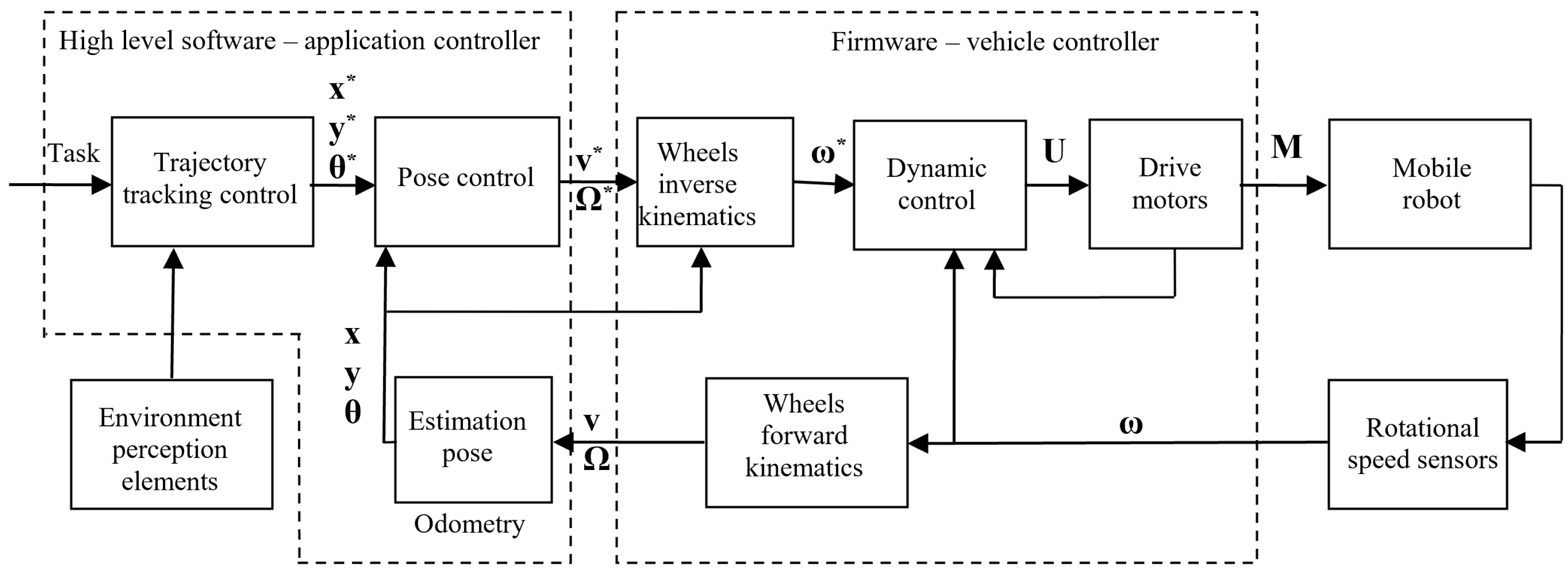
Figure 2 it is shown the structure of the controller, derived from a typical cascade structure which contains 3 control loops: the trajectory planning loop, the kinematic loop and the dynamic loop. In this way, if the dynamic loop is much faster than the kinematic loop which, in turn, is much faster than the planning loop, then the stability of the system is guaranteed.
The position of the mobile platform which navigates in 2D space can be completely specified by means of the pose, consisting of three scalar sizes:
The pose derivative generates the speed vector:
Dynamic control can include a current control loop and takes into account the inertial masses of rotation and translation of the robot, as well as strong forces and torques in order to obtain control voltages, , of motors which in turn are used to determine imposed rotation speeds, . High level control can consider some aspects in the phase of generating the reference path (avoidance of collisions, singular configurations, etc.) depending on the degree of intelligence of the designed mobile robot. Starting from the measured rotational speeds, , using the direct kinematic model of the mobile robot, the speed vector from Equation (2) can be obtained and then the position estimation. In this way it is possible to implement the middle level control, which involves a control of the position from a kinematic perspective.
3.1. Mechanical Architecture
The platform used in this study consists of four Mecanum wheels driven by individual motors and has important capabilities, especially for industrial environments, as it is able to move in any direction whilst spinning around its vertical axis. In order to minimize the vibrations caused by the spacers between rollers which affect the stability, the platform is provided with suspension mechanism based on traditional dampers. The robot was completely set up for autonomous navigation utilizing ROS, camera and a 360 LiDAR.
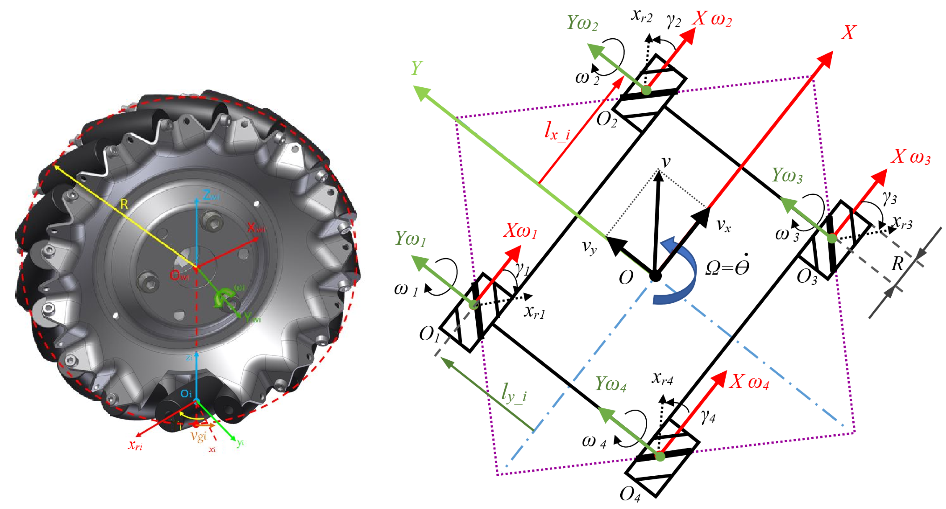
Figure 3 presents the geometrical model of the OMR prototype with the coordinates system assignments to each wheel, platform configuration, and all variables necessary for developing the kinematic model. As described at the beginning of
Section 3, the control system deals with two kinematic transformations: the forward model which uses the speeds of all wheels to determine the relative speed of the platform, while the inverse kinematic model takes the components of the decomposed relative speed of the platform in order to obtain the required speed for each wheel.
The building process of the kinematic model of the omnidirectional platform with four Mecanum wheels having the arrangement of rollers direction in a square is a classic bottom-up approach, that starts from the process of composing the movement () in the Cartesian coordinate system of the roller that is in contact with the floor (). The movement is translated to the wheel’s angular velocity () with its attached coordinate system (), and the wheel’s radius, R. The resulting velocity vector v is determined by instantaneous translation velocities of the robot ( respectively ) in the coordinate system of chassis .
The position of each wheel
i is uniquely determined in relation to the distance considered as a vector (thus having a sign depending on the direction of the axis to which it refers) as well as rotation angle between the wheel frame and roller frame (for a Mecanum wheel this angle is equal
). In concordance with notations from
Table 1 the particularized symmetric values for the structural parameters from
Figure 3 are presented in
Table 2. Therefore the impact of the linear velocity vector (
) of the wheel
i and the velocity of the roller in contact with the ground (
) on the velocity vector of the robot can be calculated [
26,
27,
28] by:
Because
is an uncontrollable variable of the passive roller, it will be eliminated through substitution from Equations (3) and (4):
By customizing the parameters from
Table 2 for each wheel and transforming linear velocity of each wheel to angular wheel velocity (
), the wheels speed equations can be written as:
The matrix representation, which is the most used method for inverse kinematics calculations, is presented in Equation (7):
The inverse kinematic Jacobian matrix J of the OMR is expressed as:
In order to obtain the forward kinematic equations, used for calculating the linear and angular speeds of OMR relative to the ground, the deduction starts from Jacobian matrix, which has 4 × 3 dimensions, it must be used a pseudo inverse matrix
such that
, which it is determined with the formula from [
27]:
The values calculated for OMR with conventional notations from
Table 2 for forward kinematics are:
And the resultant direct kinematics transformation representing linear and angular velocities of the OMR relative to ground is:
The matrix equations Equations (7) and (11) are essential components of the vehicle controller firmware implementation that is presented in
Section 3.3.
3.2. Hardware Architecture
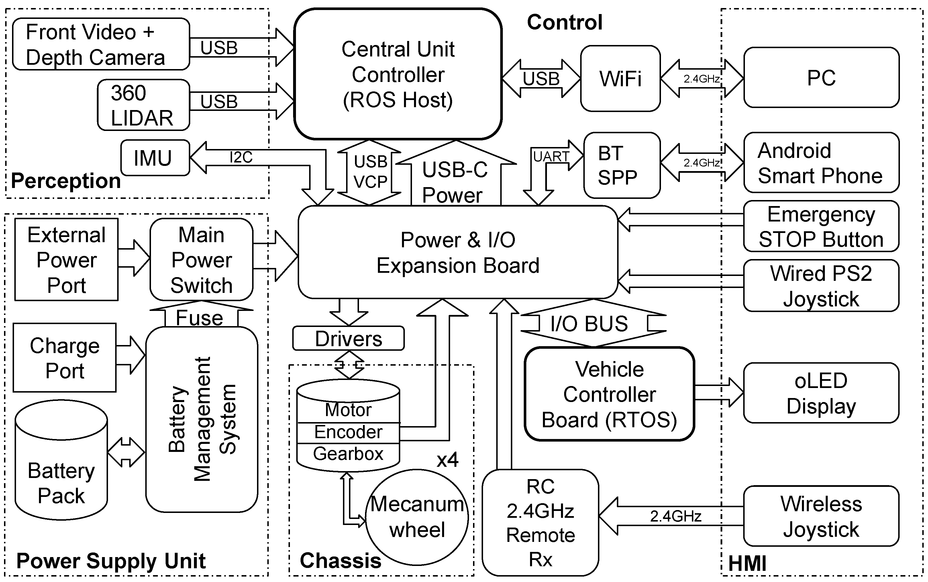
The architectural design diagram of the hardware platform [
29] is presented in
Figure 4. The components of the architecture are grouped by their functional role: power supply unit, chassis with the mechanical actuators, perception layer (that includes the environment scanning sensors), and the human machine interface (HMI) elements. The remaining interlinking components, that are not part of the marked groups, are part of the control and communication layer.
Furthermore, the control components can be subdivided in two logical levels, in accordance with the control diagram presented in
Figure 2: high level control implemented in the ROS nodes running on the central unit controller and the low level control functions implemented in the firmware of the vehicle controller.
The power supply unit is customized in order to provide flexibility between mobility, required during dynamic tests, and autonomy, needed during development and static tests. For this purpose it features a main power switch that allows to select between the internal power source (Lithium-Ion battery pack that includes a battery management system), an external power source and the power off mode.
The chassis is equipped with four Mecanum wheels. Each wheel is actuated using a separated 24 DC Motor fitted with a quadrature encoder having 500 increments per mechanical rotation and an 18.5:1 ratio planetary gear box speed reduction for traction torque amplification.
The HMI provides system monitoring functions and several local or remote control options, including an emergency stop button. The embedded vehicle controller state (status, control source, wheels’ speed references and actual values, power supply voltage) can be directly observed on the organic light emitting diode (o-LED) mini display attached to the control board. The same state information can be viewed remotely using an Android™smart phone application connected over a BlueTooth™ serial port profile (BTSPP) link. In addition to viewing the state information, the Android™application can also be used for manual remote control of the platform and for tuning the wheel’s proportional-integrative speed controllers’ parameters. As alternative methods for low level remote control are provided a local (wired) Play Station™2 (PS2) compatible joystick and a standard radio remote controlled (RC) 6 channel servo receiver for manual wireless remote operation. It is also possible to achieve HMI interaction using the high level control layer through special PC applications that implement remote control ROS nodes.
The perception layer contains the environment scanning sensors: the 360° LiDAR, a video camera with depth perception and an inertial measurement unit (IMU). The LiDAR is used for scanning the general occupancy map of the surroundings. The front video camera with depth perception is used for a more accurate detection of obstacles and objectives on the immediate path of the robot. The IMU provides additional information that can be correlated with the movement commands in order to improve the odometry or to detect abnormal operation.
The central unit controller is a NVIDIA Jetson Nano™ system operated using a GNU/Linux Ubuntu distribution which represents the host for the ROS that runs the nodes dealing with high level control layer. The central unit controller provides access to the perception layer and can dictate the robot’s relative motion speeds through a virtual serial COM port (VCP) over the universal serial bus (USB) port on which the vehicle controller is connected, in order to guide it on a specific trajectory. The ROS nodes and the NVIDIA Jetson Nano’s Ubuntu operating system can be remotely accessed from a PC using Wi-Fi connection made available through a USB dongle network card.
The vehicle controller is a STM32F103RC micro-controller from ST Microelectronics® which is hosted on an expansion board used for distributing the power and interconnecting with the rest of the attached modules. The central unit controller is powered from the expansion board over dedicated USB-C connector and data connection to the vehicle controller is made through an additional USB connection that tunnels VCP serial connection. The motor drivers, motor encoders, emergency stop button, remote control receiver, blue-tooth module and the PS2 joystick are also attached on the expansion board connectors which links them to the vehicle controller.
3.3. Vehicle Controller Firmware
The vehicle controller is designed to be commanded in autonomous mode through the USB VCP connection by the ROS software, which represents the navigation abstraction layer (NAL), running on NVIDIA Jetson Nano™, but also manually through the other HMI channels.
On the vehicle controller it runs a customized implementation of FreeRTOS™, real time operating system (RTOS) distribution maintained by Amazon®. Its main responsibilities are to monitor the command sources (USB VCP, BTSPP, PS2 joystick, RC joystick), arbitrate between them, monitor the motor encoders to obtain the speeds of the wheels, sample the IMU, properly control the motor drivers to obtain the desired speed references, and report system status through different communication channels (VCP, BTSPP, and controller area network (CAN)). This responsibilities are implemented using the following set of tasks running on the RTOS software infrastructure: IMU sampling, PS2 joystick handling, o-LED display management, data reporting, and motion control.
The motion control and data reporting tasks are essential for the implementation of the hardware abstraction layer (HAL) of the OMR. For this reason the firmware includes the parameters of the OMR geometry needed to evaluate the inverse kinematics Equation (7) for controlling the wheel speeds according to the requested relative motion reference speeds, while at the same time the data reporting task is using the same parameters for evaluating the direct kinematics Equation (11) required to obtain the actual OMR relative motion speeds used by the central unit controller for odometry.
3.4. High Level Software and the Control Application of the ROSY Platform
ROS is a flexible framework for writing robot software. It is a collection of tools, libraries, and conventions that aim to simplify the task of creating complex and robust robot behavior across a wide variety of robotic platforms. ROS can integrate, run or support any application and also provides: operating system (OS) services, HAL, low-level device control, implementation of commonly-used functionalities, message-passing between different processes and package management. There are many advantages of using ROS, especially due to the fact that it is open-source [
30,
31].
ROS application is the high level software that allows the developer to integrate the OMR into a HiL process. A ROS application includes individual pieces of software that are integrated into the ROS ecosystem as ROS nodes.
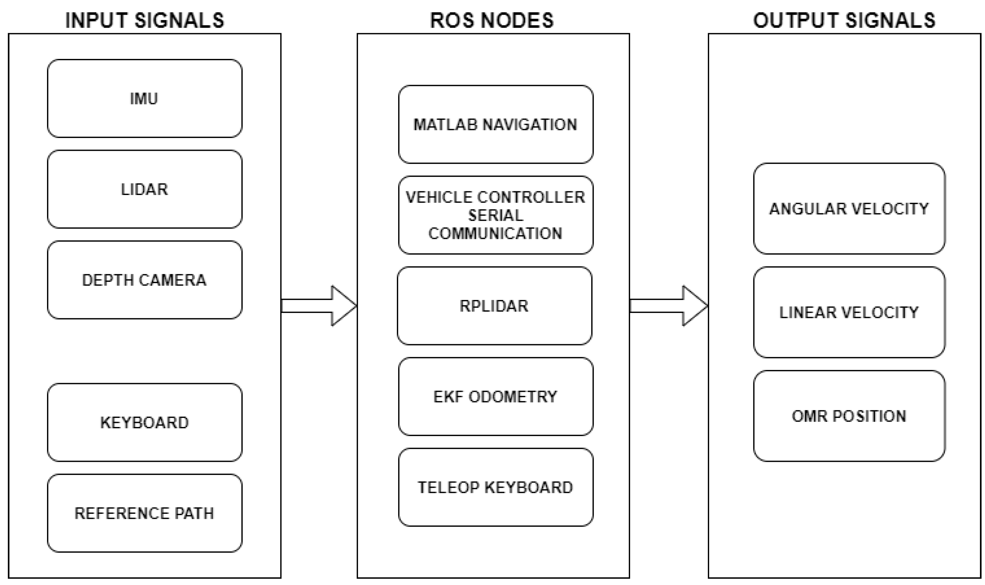
The relationship between nodes running on NVIDIA Jetson Nano is illustrated in
Figure 5. The underlying communication of ROS is based on XML-RPC protocol. It allows cross-platform software to make remote calls by sending and receiving messages in XML format.
The main nodes that enable the serial communication and provide information about robot’s real-time position while executing a certain task are:
Matlab navigation ROS node specially designed for the HiL architecture proposed in the paper
Vehicle Controller serial communication ROS node: enables the serial communication and the data transfer between NVIDIA Jetson Nano and STM32 robot controller. The ROS system receives data sent by the lower level controller and, at the same time, sends instructions to the micro-controller to handle the robot, by specifying the desired orthogonal translation speeds and the rotational velocity.
LiDAR ROS node “rpLidarNode”: enables the LiDAR which communicates with the application controller via a serial port and used, further on, in the ROS software applications.
Extended Kalman filter (EKF) Odometry ROS node: provides encoder odometer data and IMU data.
Teleop Keyboard node: used in manual mapping of OMR environment.
4. Real-Time Motion Control Using a ROS Node Implemented in MATLAB
ROS Toolbox provides an interface that allows the connection between Matlab Simulink and ROS ecosystem. Using this facility, there is possible to create a cross-platform network of ROS nodes. The toolbox includes MATLAB functions and Simulink blocks to import, analyze, and play back ROS data recorded in rosbag files [
32]. It is also possible to connect to an existing live ROS network to access ROS messages. ROS Toolbox enables the generation of ROS nodes from a Simulink model and also to integrate the simulated ROS node into a ROS network from a physical hardware [
30].
The toolbox includes algorithms for collision checking, trajectory generation and forward or inverse kinematics. For mobile robots, such as the OMR, it includes algorithms for mapping, localization, path planning, path following and motion control. The toolbox provides reference examples of common industrial robot applications and it also includes libraries of commercially available industrial robots that can be imported, visualized and simulated. In order to evaluate the performances of the proposed approach, the first goal was to implement a ROS node package using the features that Matlab provides to perform localization of the OMR [
33].
4.1. ROS Node Implementation
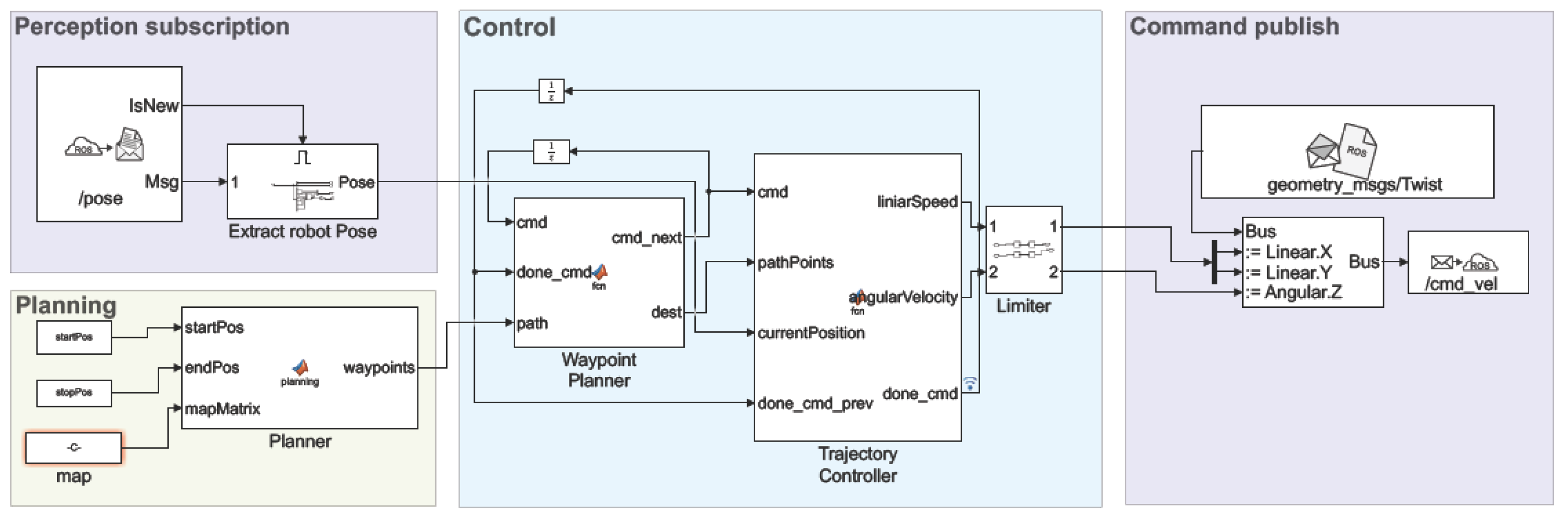
Figure 6 shows the modules implemented, the main part consists of the
block with the
whose role is to calculate the command for linear velocity and angular speed using two PID type controller in order to reach the destination goal. This command is sent to the next block, being saturated before to be published in the last block throw the topic
. During navigation through a previously constructed map, the robot behaves as expected with only a few shortfalls. These errors were most likely caused by errors in odometry data.
To generate a route for the robot to move in an optimal way it is needed a map space for a path planner algorithm. In , the coordinates [xy] are sent to as a goal destination. represents the current position of the robot acquired for topic and when the goal position was reached the signal is send for receiving the new position. Because the robot has 60 on every side, it is necessary to insert a threshold applied on the edges of the obstacles. This threshold has two effects, one is to create a space bounds in order to avoid collision of the robot with the obstacles and the second is for path planning, where we use a probabilistic roadmap algorithm with the purpose to eliminate areas where it is not necessary to calculate the network graph of the possible path. Also position of the robot on the map is known in real time by subscribe to topic generated by node. In the block, position of the robot on the map is known in real time by subscribe to topic generated by node. Through the block, the develop a feasible path from its location to the goal utilizing the probabilistic road map and generates a road path for SLAM algorithm.
4.2. Practical Experiments and Evaluation
This section presents the control performances of the OMR using the proposed approach. Real time experiments are obtained using ROS and Matlab features. The experimental flow has two main parts:
test run and data acquisition in Matlab and
data processing and reporting according with the proposed approach used in the
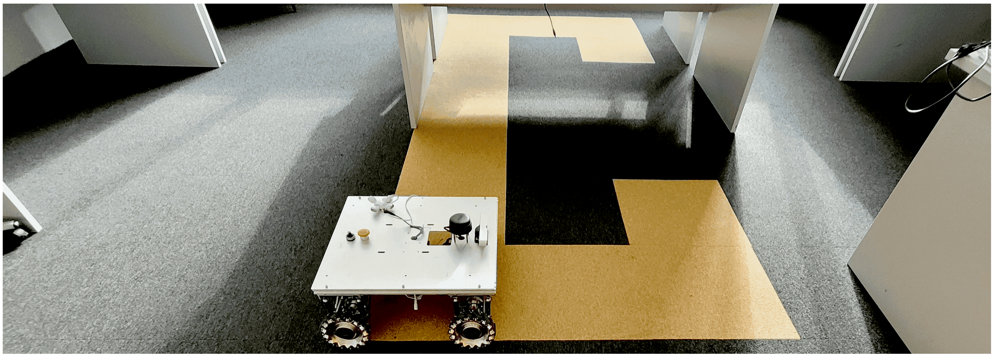
Figure 5. The first part, the OMR platform is subject to several scenarios and the data are acquired in real time from IMU and LiDAR sensors. The working environment is a restricted area, the real platform and the environment are illustrated in
Figure 7. In the second part, the tests are reported and analysed from the reference tracking performance perspective. The following parameters were monitored on the OMR: raw sensor data (
movement, linear speed and angular speed) and reference trajectory. The first experiments were performed considering circle and square reference signal, respective, considering reference signals for position
x (forward movement) and
y (lateral movement). Further, a map of the environment is built based on LiDAR scans, then the OMR navigates inside the map following the reference trajectory.
The simple motion controller moves the OMR to a new waypoint in two phases: an initial azimuth orientation (if the azimuth differs significantly), followed by a longitudinal translation together with slight azimuth corrections until a vicinity of the destination is reached. Due to the symmetry of the OMR operation, all translations are expected to perform in a similar way, so the longitudinal translation motion was studied for the tracking performance in the square trajectory experiment.
Tests were performed and the platform’s relative velocity to ground was recorded using a set of local coordinates (considering x the longitudinal movement axis and y the lateral movement axis), and the angular velocity around the vertical z-axis.
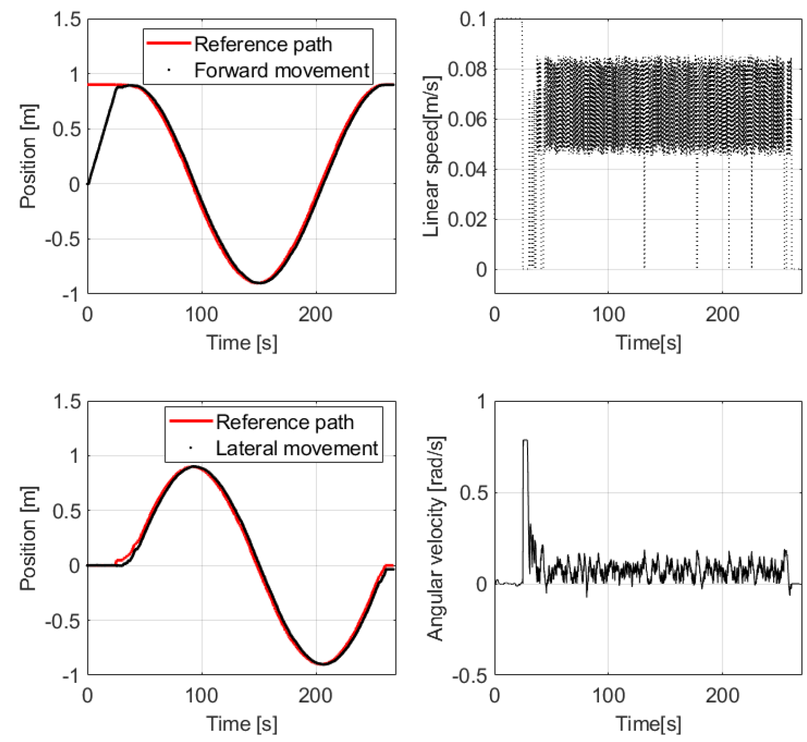
4.2.1. Circular Trajectory
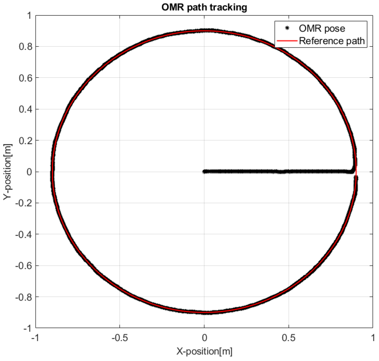
Figure 8 shows with the red line the target circular trajectory with 1
radius is given as reference and with the black points the actual trajectory of the robot, considering that it starts from the origin of the circle, approaches in a straight line the periphery, then aligns with the closest tangent to the circle and follows the path in the trigonometric direction.
Figure 9 illustrates the performances of the OMR, when attempting to follow the circular path. It can be observed that the OMR reaches in the vicinity of the reference points on both
x-axis and
y-axis, while the control effort is being accomplished by the linear and angular speed controllers.
The linear speed of the platform illustrated in
Figure 9 reaches the maximum
/
allowed by the controller when navigating from the origin to the periphery, then it returns to 0
/
while the controller rotates the platform tangent to the circle. When the platform orientation becomes tangent, the linear speed controller accelerates towards the next way-points on the circular path, but it is visible that the linear speed is limited by the controller at about maximum
/
and it oscillates because while following the circular trajectory the orientation of the platform needs continuous realignment, fact that triggers the linear speed reduction to guarantee the proper reference tracking.
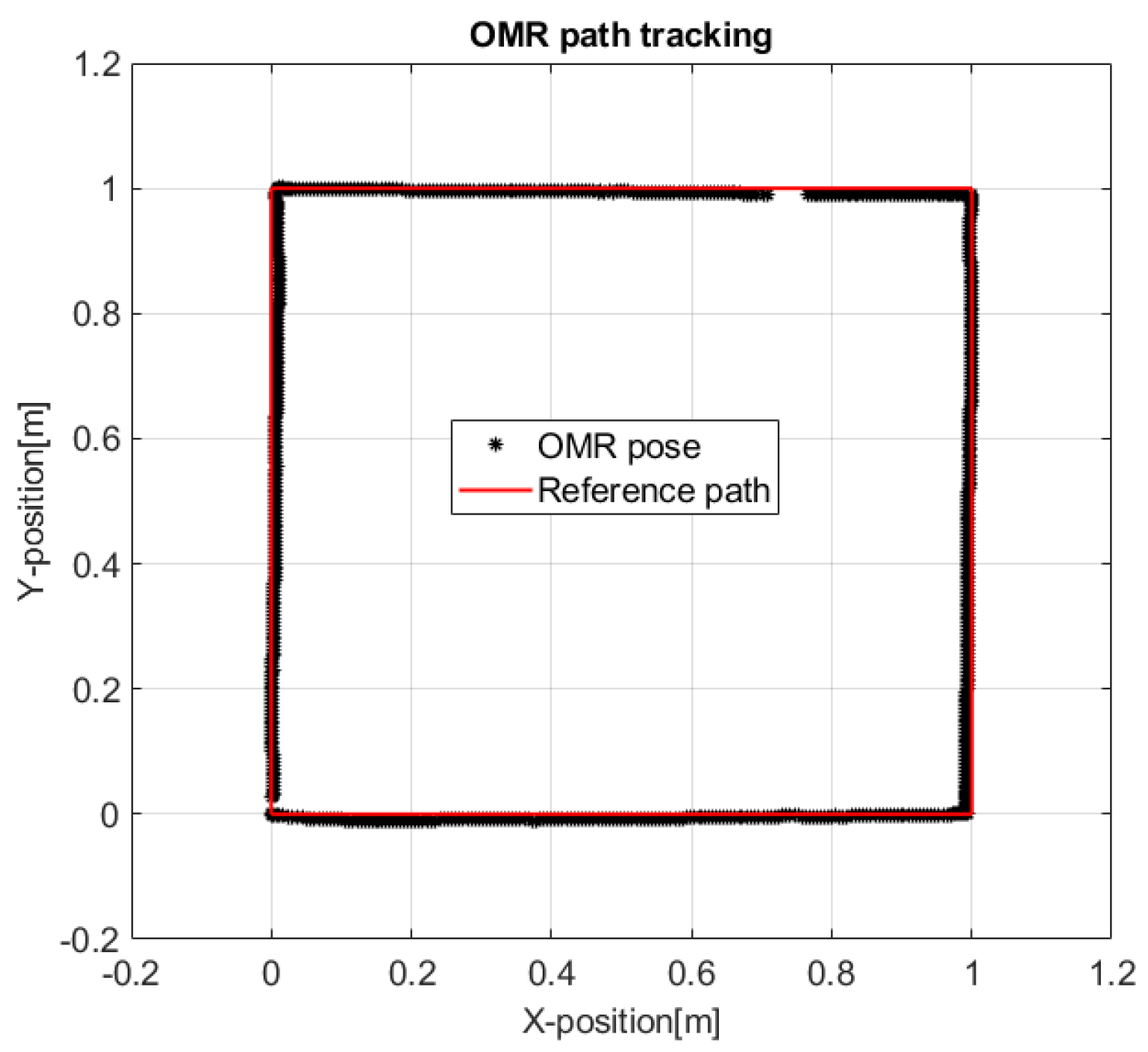
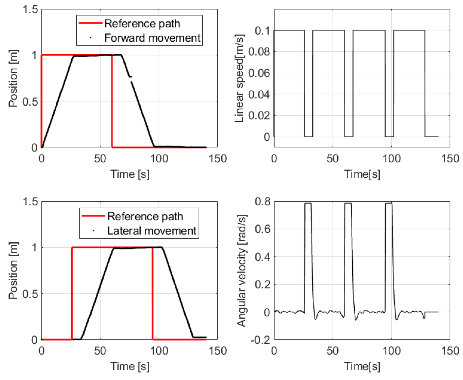
4.2.2. Square Trajectory
Figure 10 illustrates with the red line a square reference trajectory with each side measuring 1
, which is defined by only four way-points representing the corners, while with the black points it is marked the actual trajectory of the OMR in-between them. The tracking performances considering that the robot starts from the origin point, reaches the goal points and follows all four sides in about
min, as
Figure 11 shows.
In
Figure 11 it is also easily visible how the linear speed controller and angular speed controller interact: when the desired motion direction differs significantly from the actual direction the linear speed reference is switched to zero in order for the angular speed controller to properly adjust the direction towards the target.
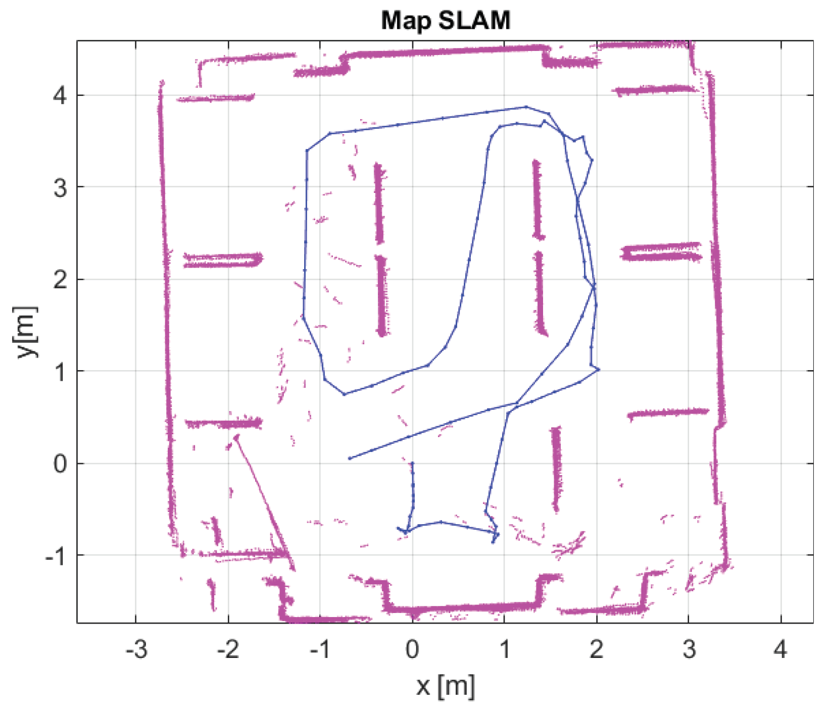
4.2.3. Navigation Using the Map Obtained with SLAM
Autonomous map building focuses on the widely used SLAM approach. The platform keeps track of its motion using odometry while navigating in the known environment as illustrated in
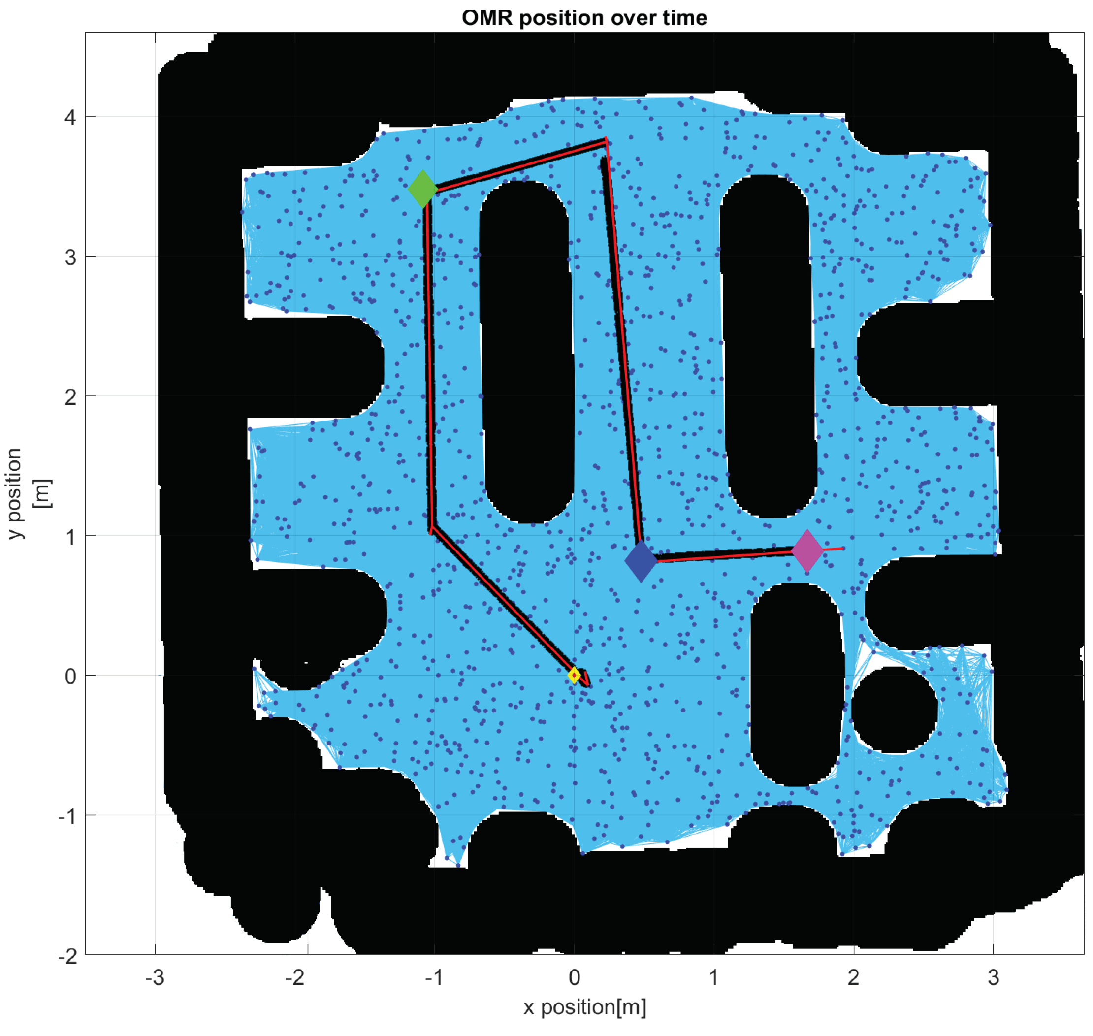
Figure 12. The experiments build, in the first phase, the environment map based on LiDAR scans, while in the second phase, robot navigates inside the map which is represented in
Figure 13. In order to perform the real time tests, a ROS node package was used, based on the features that Matlab provides to perform localization and mapping.
The approach was to create a LiDAR SLAM object and set the map resolution and max LiDAR range. The maximum LiDAR range was set to 4 m, while it is smaller than the maximum scan range, which is 12 m, as the laser reading are less accurate near maximum range. The grid map has a resolution of 2 cm per division. However, odometry uncertainty confuses the robot about its current position.
To generate a route for the robot to move in an optimal way, it is needed a map space for a path planner algorithm. Because the robot has 60 cm on every side, it is necessary to insert a threshold applied on the edges of the obstacles, an inflation of the size of the obstacles which can be observed when comparing
Figure 12 with
Figure 13. This threshold has two effects, one is to create a space bounds in order to avoid collision of the robot with the obstacles and second is for path planner, where a probabilistic road-map algorithm is used, as is illustrated in
Figure 13. In order to have a realistic static map of the indoor environment where only the allowed and forbidden areas are represented, the occupational map was binarized and saved in the robot’s memory, for a later use in the navigation node.
5. Conclusions
The strategic control level of the OMR and implementation presented in this article use a HiL approach designed for integration in the Matlab environment, in which it will be developed the strategy for managing the robotic structure. The strategy is expected to be complex because it depends on a large number of factors, among which the OMR’s architecture, the decision algorithms that take into account the activity to be performed, the necessary operating accuracy, the operating speed and the energy consumption optimization. At this level, the complex action can be decomposed into elementary operations that can be transmitted to be executed by the lower hierarchical level represented by the vehicle controller.
MATLAB is recognized as a very powerful tool for testing control systems satisfying the need for rapid control prototyping. Facilities offered by the Robotics Systems Toolbox has contributed to increasing interoperability with mobile robotic systems that prefer to use the ROS environment more and more.
The preliminary experimental results from laboratory for testing of the four Mecanum wheels mobile platform was done from three perspectives. The first is related to the validation of tracking predefined trajectories, usually used in the testing of mobile robots: circle and square. The second perspective refers to building a map of the environment based on LiDAR scans and the position using SLAM algorithm, procedure used partly in commissioning of industrial mobile robot. The last perspective is the performing of navigation between points defined in the map which qualified the mobile platform to be equipped with conveying system and used in logistic environment as it is the aim of ROSY-Logistic project.
Future research will be directed towards the development of reactive control algorithms in order to cope with the dynamic changes that may occur in the workspace captured with the static map inclusively equipping the platform with other perception systems to obtain accuracy of navigation.


 ,
, 


