Abstract
A novel compact planar 2 × 2 antenna system with super-wide bandwidth is presented in this paper. The MIMO antenna has four square-shaped patches with two slots in each that are interconnected with each other using four strip lines printed on a substrate of Rogers Duroid RT 5880 with relative permittivity of εr = 2.2 and tangent loss of δ = 0.0009. The proposed antenna system has a partial ground plane with two enhancement fractured slots. The design is characterized by a super-wide impedance starting from 15.2 to 62 GHz (a bandwidth of 46.8 GHz) and compact total system size of 11.2 × 15.25 mm2 with a thickness of 0.12 mm. The proposed MIMO design has omnidirectional radiation pattern for far field and the achieved peak gain reaches 13.5 dBi. The presented planar antenna which relies on computer aided design, has been designed and simulated using an industrial standard simulation code. Its performance results showed that the MIMO design is characterized by super wide bandwidth, omnidirectional radiation pattern, and high-power gain with miniaturized physical size; thus, it is suitable for radio-frequency identification (RFID) systems, fifth-generation applications, ultra-wideband systems, and others.
1. Introduction
Lately, a dramatic growth in data rates has found a high demand with rapid development of the current wireless systems [1]. Microstrip antennas have played a crucial role in microwave and radio frequency transceiver due to their characteristics such as low-profile high gain, light weight, low fabrication cost, and simplicity [2,3,4,5,6,7,8,9]. Furthermore, a wide range of wireless applications containing radio-frequency identification (RFID) have been found [10]. Currently, wireless applications are shifting globally from long-term evolution (LTE) to the fifth-generation systems in order to overcome data rates, frequency band shortages, and future needs. Recently, many scientific studies have been accomplished to shift from Ultra High Frequency (UHF) spectrum bands (300 MHz to 3 GHz) to the millimeter wave bands such as 27.5–28.35 GHz, 37–37.6 GHz, 37.6–40 GHz, and others [11,12,13,14]. Figure 1 illustrates the fifth generation of wireless communications frequency spectrum bands. Figure 2 shows a brief information about the fifth generation (5G) main features.
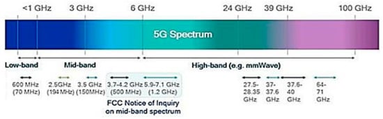
Figure 1.
The fifth-generation wireless communications frequency spectrum [15].

Figure 2.
Overview of fifth generation (5G) communication technology [15].
For microstrip patch antennas (MPA), the mechanism of radiation occurs due to the discontinuities at the truncated edges of the microstrip lines. Thus, the antenna radiation appears slightly higher than its actual structure dimensions and the microstrip transmission line length has to be less than half of the wavelength at which the frequency is used. Several techniques have been studied and developed previously in order to enhance the bandwidth spectrums and to minimize the physical footprint, which makes the microstrip patch antennas widely popular in several wireless communication systems [16].
Presently, the multiple input multiple output (MIMO) antenna systems are massively applied in wireless devices [14,17]. Thus, a new (MIMO) antenna system is proposed in this article by targeting the current challenge of extremely increasing data rates and to maximize the channel capacity at the environment of multipath propagation [18,19,20,21]. In order to overcome many drawbacks in many previous designs, this paper proposes a new design of the MIMO antenna system that is characterized by operating frequency, power gain, and radiation pattern with reduced structure size. In the following section, the proposed antenna system configuration is introduced with details.
2. Antenna Configurations
The geometry of the proposed antenna system, which is designed and simulated using an industrial standard simulation code, is revealed in Figure 3. The figure illustrates the top and bottom views of the MIMO antenna structure. It is composed of four patches (2 × 2 MIMO system) with two slots on each patch that are loaded to enhance the performance printed on the same side and interconnected using high impedance strip lines. The patches are fed by a single 50 Ω mictrostrip line connected to one antenna. The MIMO antennas are printed on a Rogers Duroid RT 5880 substrate with relative permittivity of εr = 2.2 and a loss tangent of δ = 0.0008, under which is a partial ground plane with two fractured I-shape slots. The overall obtained dimension of the suggested compact design is 15.25 × 11.20 mm2 with a thickness of 0.13 mm, where each square shape patch has a size of 4.3 × 5.3 mm2. Table 1 presents the 2 × 2 MIMO antenna structure configuration parameters in millimeters after optimization. The suggested MIMO system has a similar design and low profile, and it is easy to fabricate. The four patch dimensions were calculated using the following ordinary standard antenna design equations, which are shown below [22]. The next section shows the parametric study and the optimum results of the proposed antenna.
where Wp and Lp are the patch width and length, respectively; C is the light speed; f is frequency; σ is the conductivity; εr is the relative permittivity; εeff is the effective permittivity; and h and W are the height and substrate width, respectively.
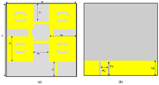
Figure 3.
Geometry of the presented 2 × 2 MIMO antenna: (a) top view, (b) bottom view.

Table 1.
Parameters of the proposed 2 × 2 antenna, as shown in Figure 3.
3. Parametric Study and Results
The optimization process is performed to obtain the smallest antenna dimensions (compact structure with the appropriate substrate) that exhibits the omni-directional pattern with minor distortions at millimeter waves, super-wide bandwidth, and higher gain. The reflection coefficient versus the operating frequency of the proposed antenna system is revealed in Figure 4 for several commonly used substrate materials (FR-4, Duroid Roger RT 5880, and RO3003 with relative permittivity of 4.3, 2.2, and 3.3, respectively). The design using a substrate of RT 5880 had a super-wide bandwidth from 15.2 to 62 GHz (a bandwidth of 46.8 GHz) in terms of S11 < −10 dB standard. However, using other substrate material (FR-4 and RO3003) for this design led to a smaller bandwidth and less impedance matching at several frequencies. The partial ground plane length was optimized as illustrated in Figure 5. It can be noticed that at Lg = 3 mm, the design reflection coefficient had the widest bandwidth compared to others. Moreover, the microstrip feeding line width was highly sensitive parameter and it was observed that at wf = 0.3 mm, the proposed design had the widest operating frequency, as shown in Figure 6. On the other hand, at wf = 0.2 and 0.4 mm, the S11 parameter had either shorter bandwidth or went beyond the −10 dB level. The normalized power radiation pattern at the resonant frequencies for the main orthogonal planes (elevation and azimuth) is displayed in polar form in Figure 7 at two resonant frequencies. In general, the design radiation pattern had an omni-directional shape with minor distortion at higher frequencies due to the high-power radiation. Thus, the proposed MIMO system can be inserted inside the wireless system at any situation due to its wide radiation feature. The peak power gain response during the entire operating frequency at two different standard simulation codes (Computer Simulation Technology Microwave studio (CST) and High Frequency Structure Simulator (HFSS)) showed that the MIMO antenna had extreme high-power gain, reaching 13.5 dB, as shown in Figure 8. It can be remarked that the design was highly sensitive in terms of structure parameters; thus, antenna prototyping has to be performed with accuracy to reduce the fabrication tolerance and prevent any mismatching.
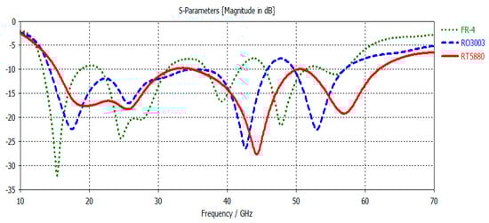
Figure 4.
Reflection coefficient (S11) for the proposed design using different substrate material (FR-4, RO3003, and RT5880) versus frequency in GHz as part of the optimization process.
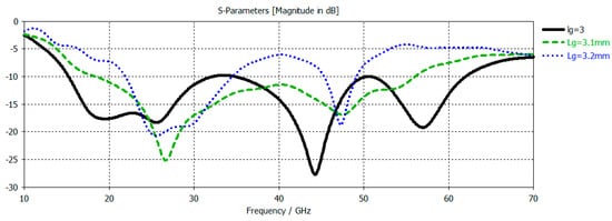
Figure 5.
The effect of partial ground plane length (Lg) on the reflection coefficient (S11) versus frequency in GHz.
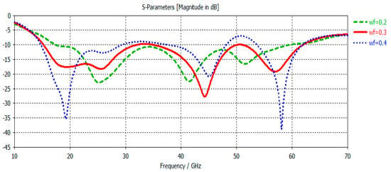
Figure 6.
Reflection coefficient (S11) versus frequency in GHz for several feeding line widths.
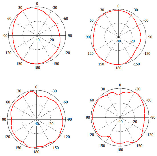
Figure 7.
Simulated radiation pattern at E-plane (elevation) and H-plane (azimuth).
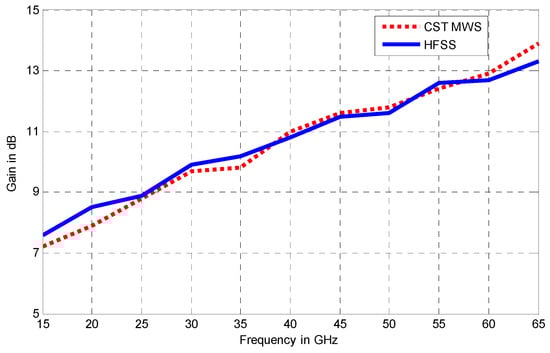
Figure 8.
Simulated power gain of the proposed Ultra wide band Multiple input Multiple output (UWB MIMO) antenna.
Table 2 presents a short comparison between the proposed MIMO antenna system with several previously published antenna designs. It can be remarked that the suggested patch antenna exhibited the highest bandwidth of 46.8 GHz from 15.2 up to 62 GHz (Figure 4); furthermore, the design had a high compact physical structure size compared to analogue designs. Therefore, the proposed antenna can be easily placed inside miniaturized wireless gadgets and applications, and more space could be saved for other wireless components within the system.
Table 2.
Comparison between the proposed antenna system with previously published papers.
4. Conclusions
A new 2 × 2 super-wide bandwidth MIMO antenna system is presented in this article. The proposed antenna system was designed and simulated using two standard modeling codes (CST Microwave studio and HFSS). Furthermore, patch antenna parameters such as reflection coefficient, radiation patterns, and power gain for the designed system were optimized. This MIMO antenna system consists of four square-shaped patches with a slotted/fractured partial ground plane to obtain better performance. The presented MIMO antenna system has a very compact structure size; the overall physical volume is 11.2 × 15.25 mm2 with a thickness of 0.12 mm. The overall fractional bandwidth of antenna system was measured as 121.24%, where the total operating frequency was 46.8 GHz. Moreover, the peak power gain value of the proposed antennas system was measured as more than 13.5 dB. On the basis of the presented antenna characteristics, we argue that the designed patch is appropriate for the millimeter wavelength wireless communication system, radio-frequency identification (RFID) systems, fifth-generation applications, ultra-wideband systems, and others.
Author Contributions
Supervision, original draft, and writing—H.A.; review, resources, and editing—M.A.H.E. All authors have read and agreed to the published version of the manuscript.
Funding
The authors would like to thank the deanship of scientific research at University of Ha’il for funding this work under the research project (150166).
Institutional Review Board Statement
Not applicable
Informed Consent Statement
Not applicable
Data Availability Statement
The data presented in this study are available within the article.
Acknowledgments
The authors would like to thank the deanship of scientific research at University of Ha’il for funding this work under the research project (150166).
Conflicts of Interest
The authors declare no conflict of interest.
References
- Lee, K.F.; Luk, K.M. Microstrip Patch Antennas; Imperial College Press: London, UK, 2011. [Google Scholar]
- Xu, K.-D.; Xu, H.; Liu, Y.; Li, J.; Liu, Q.H. Microstrip Patch Antennas with Multiple Parasitic Patches and Shorting Vias for Bandwidth Enhancement. IEEE Access 2018, 6, 11624–11633. [Google Scholar] [CrossRef]
- Lee, K.F.; Tong, K.-F. Microstrip Patch Antennas—Basic Characteristics and Some Recent Advances. Proc. IEEE 2012, 100, 2169–2180. [Google Scholar] [CrossRef]
- Deshmukh, A.A. Broadband slot cut shorted sectoral microstrip antennas. IET Microwaves Antennas Propag. 2017, 11, 1280–1287. [Google Scholar] [CrossRef]
- Kandwal, A.; Khah, S.K. A Novel Design of Gap-Coupled Sectoral Patch Antenna. IEEE Antennas Wirel. Propag. Lett. 2013, 12, 674–677. [Google Scholar] [CrossRef]
- Liang, Z.; Liu, J.; Zhang, Y.; Long, Y. A Novel Microstrip Quasi Yagi Array Antenna with Annular Sector Directors. IEEE Trans. Antennas Propag. 2015, 63, 4524–4529. [Google Scholar] [CrossRef]
- Wu, J.; Yin, Y.; Wang, Z.; Lian, R. Broadband Circularly Polarized Patch Antenna with Parasitic Strips. IEEE Antennas Wirel. Propag. Lett. 2015, 14, 559–562. [Google Scholar] [CrossRef]
- Wong, K.-L.; Sze, J.-Y. Slotted rectangular microstrip antenna for bandwidth enhancement. IEEE Trans. Antennas Propag. 2000, 48, 1149–1152. [Google Scholar] [CrossRef]
- Lu, J.-H. Bandwidth enhancement design of single-layer slotted circular microstrip antennas. IEEE Trans. Antennas Propag. 2003, 51, 1126–1129. [Google Scholar] [CrossRef]
- Gaspari, F.; Quaranta, S. Nanostructured Materials for RFID Sensors. In Nanomaterials Design for Sensing Applications; Elsevier BV, 2019; pp. 93–128. Available online: https://www.sciencedirect.com/science/article/pii/B9780128145050000035 (accessed on 13 December 2020). [CrossRef]
- Al-Saif, H.; Usman, M.; Chughtai, M.T.; Nasir, J. Compact Ultra-Wide Band MIMO Antenna System for Lower 5G Bands. Wirel. Commun. Mob. Comput. 2018, 2018, 1–6. [Google Scholar] [CrossRef]
- Matinmikko, M.; Latva-Aho, M.; Ahokangas, P.; Seppänen, V. On regulations for 5G: Micro licensing for locally operated networks. Telecommun. Policy 2018, 42, 622–635. [Google Scholar] [CrossRef]
- Marsden, R.; Ihle, H.-M. Mechanisms to incentivise shared-use of spectrum. Telecommun. Policy 2018, 42, 315–322. [Google Scholar] [CrossRef]
- Dighriri, M.; Lee, G.M.; Baker, T. Measurement and Classification of Smart Systems Data Traffic Over 5G Mobile Networks. In Technology for Smart Futures; Dastbaz, M., Arabnia, H., Akhgar, B., Eds.; Springer: Cham, Switzerland; Available online: https://link.springer.com/chapter/10.1007/978-3-319-60137-3_9 (accessed on 20 December 2020)ISBN 978-3-319-60136-6. [CrossRef]
- Qualcomm Technolgies, On the Path to Opening More Spectrum for 5G in the U.S. Available online: www.qualcomm.com, (accessed on 4 October 2017).
- Alibakhshikenari, M.; Virdee, B.S.; See, C.H.; Abd-Alhameed, R.A.; Falcone, F.; Limiti, E. Super-Wide Impedance Bandwidth Planar Antenna for Microwave and Millimeter-Wave Applications. Sensors 2019, 19, 2306. [Google Scholar] [CrossRef] [PubMed]
- Li, S.; Da Xu, L.; Zhao, S. 5G Internet of Things: A survey. J. Ind. Inf. Integr. 2018, 10, 1–9. [Google Scholar] [CrossRef]
- Wu, Y.; Ding, K.; Zhang, B.; Li, J.; Wu, D.; Wang, K. Design of a Compact UWB MIMO Antenna without Decoupling Structure. Int. J. Antennas Propag. 2018, 2018, 1–7. [Google Scholar] [CrossRef]
- Wang, F.; Duan, Z.; Li, S.; Wang, Z.-L.; Gong, Y. COMPACT UWB MIMO ANTENNA WITH METAMATERIAL-INSPIRED ISOLATOR. Prog. Electromagn. Res. C 2018, 84, 61–74. [Google Scholar] [CrossRef]
- Wu, L.; Xia, Y.; Cao, X.; Xu, Z. A miniaturized UWB-MIMO antenna with quadruple band-notched characteristics. Int. J. Microw. Wirel. Technol. 2018, 10, 948–955. [Google Scholar] [CrossRef]
- Usman, M.; Abd-Alhameed, R.A.; Dama, Y.A.; Excell, P.S.; Zhou, D.; Ibrahim, B.; Elkhazmi, E.A. New compact dual polarised dipole antenna for MIMO communications. In 2010 International ITG Workshop on Smart Antennas (WSA); IEEE: New York, NY, USA, 2010; pp. 326–330. [Google Scholar]
- Waterhouse, R. Microstrip Patch Antennas: A Designer’s Guide; Springer Science & Business Media: Berlin/Heidelberg, Germany, 2013. [Google Scholar]
- NejatiJahromi, M.; Naghshvarianjahromi, M.; Rahman, M. Switchable planar monopole antenna between ultra-wideband and narrow band behaviour. Prog. Electromagn. Lett. 2018, 75, 131–137. [Google Scholar] [CrossRef]
- Iqbal, A.; Saraereh, O.A.; Ahmed, A.W.; Bashir, S. Mutual Coupling reduction usingF-shaped stubs in UWB-MIMO antenna. IEEE 2018, 6, 2755–2759. [Google Scholar]
- Yadav, S.; Gautam, A.K.; Kanaujia, B.K. Design of dual band-notched lamp-shaped antenna with UWB characteristics. Int. J. Microw. Wirel. Technol. 2015, 9, 395–402. [Google Scholar] [CrossRef]
- Labade, R.; Deosarkar, S.; Pisharoty, N.; Malhotra, A. Compac tintegrated Bluetooth UWB band notchantenna for personal wireless communication. Microw. Opt. Technol. Lett. 2016, 58, 540–546. [Google Scholar] [CrossRef]
- Rahman, M.; Naghshvarianjahromi, M.; Mirjavadi, S.S.; Hamouda, A.M. Compact UWB Band-Notched Antenna with Integrated Bluetooth for Personal Wireless Communication and UWB Applications. Electron. 2019, 8, 158. [Google Scholar] [CrossRef]
- Liu, A.; Lu, Y. Communication A Super-Wide Bandwidth Low-Profile Monocone Antenna with Dielectric Loading. IEEE Trans. Antennas Propag. 2019, 1. [Google Scholar]


Publisher’s Note: MDPI stays neutral with regard to jurisdictional claims in published maps and institutional affiliations. |
© 2021 by the authors. Licensee MDPI, Basel, Switzerland. This article is an open access article distributed under the terms and conditions of the Creative Commons Attribution (CC BY) license (http://creativecommons.org/licenses/by/4.0/).