1. Introduction
Rotating machines in which the drive system and the working machine are different require an adapting element in order to transmit power between the two sides. For this, a drive shaft can be used with universal joints or a particular coupling system. Ideally, the two shafts should be properly connected by a rigid coupling so that the two shafts work as one. This offers advantages such as not allowing relative movement between the two shafts, the motor, and the conduced shaft. Vertically positioned applications, such as vertical pumps, use this solution. More used, however, are flexible couplings, which aim to transmit torque or rotary motion without slipping and to compensate for axial, parallel, or angular misalignment. Additionally, the non-linear flexibility of the couplings makes the dynamics of the rotary movement smoother and improves the dynamic response for both the electric motor and the work machine. Examples of such couplings can be pumps, air pumps, engine generator sets, conveyors, crushers, vibrating screens, etc. In practice, flexible coupling can be a major contributor to performance problems of the two machines [
1,
2,
3,
4,
5,
6,
7,
8], which is why an extensive study is required for each particular application.
Flexible couplings with bolts used in industrial application are presented in a wide variety of constructive solutions, in accordance with their functional role and the demands they must respond to. These demands differ not only by dimensions for each constructive solution but also by the shape of the elastic element. Two of these variants are standardized: variant N, normal, and variant B, with spacer bush [
9]. In general, couplings are frequently used in the composition of mechanical transmissions. Flexible couplings with non-metallic elements are of great importance due to the numerous and very diverse fields of activity of equipment and installations they equip (compressors, pumps, generators, pulleys, cranes, conveyors, mixers, piston motors, general industrial applications, as well as in the metallurgical industry, the mining industry, the paper industry, and the pulp industry). In applications, the couplings are made in a great diversity of constructive solutions, a unitary and generally accepted classification of them being difficult. Specific to flexible couplings with non-metallic elements is the fact that the transmission of rotational motion and torque is achieved through the non-metallic element, which dampens shocks and vibrations and can take axial, radial, angular, or combined deviations. The stress characteristic of non-metallic coupling elements together with their size and shape of these elements represent a key design factor for mitigating the transmission of power between the sides of coupling.
Herein are presented some constructive coupling solutions for flexible coupling. These emphasize the advantages of the proposed solution, its applicability, and the way in which this solution meets the requirements of the industry. Known from literature [
10], constructive solutions that include flexible bolt coupling consist of two identical semi-couplings. In this case, the torsion moment is transmitted through the rubber sleeves mounted on the bolts, which are rigidly fixed in the other half of the coupling. The profiled sleeves mounted on the bolts are fixed at one end. This type of coupling transmits small and medium.
There are flexible couplings with rubber pins whose half-couplings are machined differently from each other. Thus, one has holes for pins, and the other has the holes machined so as to allow the mounting of rubber bushes. The holes are arranged in a circle on the circumference of each coupling half [
11,
12].
In [
13,
14] is presented flexible coupling with studs and washers or rubber bushes. The rubber elements are mounted in one coupling half on the studs, and on the other, the studs are fixed with flanges. Flexible coupling allows, within certain limits, the relative rotation of semi-couples and the variation of shafts alignment.
The Guardian Superflex coupling has two hubs: a super flexible rubber element and a bolts with self-locking nuts [
15]. The Superflex Coupling has been used world-wide on a variety of applications, including light towers, air pumps, welding sets, and other machinery with large driven inertia. The coupling consists of two cast iron hubs, a super-elastic rubber element, and a locking hardware. In a rigid coupling, the torque is transmitted from one half of the coupling to the other through the bolts, and in this arrangement, shafts need to be aligned [
16].
A flexible Rupex coupling consists of two semi-couplings, bolts and non-metallic rubber element. The non-metallic element is mounted on bolts fixed only on one side of the coupling [
17,
18]. This coupling absorbs shocks and cushions vibrations. The movement is transmitted from one half-coupling to the other through non-metallic elements fixed with bolts.
Flexible couplings with bolts and bushings are made up of two semi-coupled panels that are mounted on the shafts of the machine [
19]. These pieces allow additional torsional flexibility compared to simple cylindrical pieces.
Bolt and barrel bushings couplings are widespread on engineering applications. A flange coupling and non-metallic barrel element is used to connect trees that have a small parallel misalignment, angular misalignment, or axial misalignment. This coupling works with coupling surge. In general, this is used to assemble electric machine with working machines [
20,
21,
22].
A flexible coupling with elastic rubber bushings and pins consists of two semi-couplings with different flanges having conical bore inside and elastic rubber bushings that are mounted on notched head pins [
23]. The flexible coupling with elastic rubber bushings allows an increased load-bearing capacity and durability. The resulted stiffness characteristics are non-linear and asymmetrical. These couplings are used by the transport systems.
The rubber-cushioned sleeve bearing coupling is fast to replace, and this comprises a right half coupling body, a pin, a flexible sleeve, and a nut [
24]. The flexible sleeve can be quickly replaced, and it does not need a coaxially correction after replacement. Due to this, an improved production efficiency is obtained.
It is well known that the flexible coupling consists of fixing screws, transition sleeves, elastic rubber rings, a connecting pressure disc, a brake wheel, and studs [
25]. The multiple holes for screws and sleeves are evenly distributed alternately on the same circle in the left brake wheel. The connecting pressure disc and the brake wheel are fixedly connected by the fixed screws. The flexible coupling cannot be worn completely and has a long service life. The coupling can be easily removed.
In case of maritime couplings, it is known that these consist of two different half-couplings, a tapered sleeve, screws, drive couplings, connecting pins, elastic rubber rings, nuts, transition sleeves, and connecting pressure plates [
26]. Depending on the maritime coupling, the service life of the coupling can be extended by the transition sleeves and the rate of replacement of rubber spring rings, and the frequency of maintenance can be reduced, thus maintenance is convenient. The marine coupling especially shows its superiority when it is used in places where the maintenance is difficult.
A constructive solution of flexible coupling with bolts can be made up by two half-couplings. These have distributed holes on their circumference on a certain circle diameter where cylindrical bolts are placed. These are threaded at one end, being alternately mounted on the two semi-couplings [
27]. The movement is transmitted from one half-coupling to another by bolts and non-metallic elements.
Another constructive solution for flexible coupling with bolts and non-metallic elements consists of a coupling part placed radially and having non-metallic elastic link elements. As these elements use materials with composite structures as armatures, the different shape and the used materials generate the desired anisotropy. Additionally, the deformation characteristics of link elements will be different. Thus, the coupling is able to be adapted for a wide set of applications without major changes. In mounting processes, different solutions can be adopted by usage of specific mounting pieces having different kinds of shape, size, and screws. By usage of anysotropic link elements in correlation with disc shape, bolt placement, spacer elements, and screws, all of these generate cheaper and simpler solutions for transfer of movement by coupling. Shape, size, and materials used for link elements represent key factors for adapting to application by the amount of energy that can be absorbed inside coupling. Additionally, the coupling’s elements design influences the time response of the system at variation of torque from both sides: motor and load. Moreover, by using elastomer based link elements, these provide a lubrication effect that has beneficial effects for coupling lifespan and its usage [
28].
The study of the specialized literature in the field of flexible couplings with non-metallic elements revealed the existence of flexible couplings with non-metallic elements with relatively simple functional and constructive principles. These couplings are made in a wide range of types and sizes, being produced by specialized companies with international reputation. Because the literature in the field of flexible couplings with non-metallic elements is very poor, new research is welcome in the field.
Published articles are very rare, and the books (courses, monographs, etc. [
1,
2,
3,
4,
5,
6,
7,
8]) present general references regarding design and construction. In modern transmissions, the couplings are mounted immediately after the drive motor, which can be direct current motor with series or parallel excitation or with permanent magnets or could be asynchronous or synchronous motors. The motor or the load torque inherently vary in time function as a result of machine functioning and also as a result of functioning of the control system. The designer is able to design a coupling that smooth movement harmonics in time (speed angular acceleration in time). The dynamic response of the acting system can by optimized by the designed coupling for target work-torque, speed, and for the transient regimes. Thus, the designed coupling is able to perform oscillation dumping during transitory and stationary regimes.
The problems that appear with the couplings listed above would be related to the following: a technological achievement, generally difficult assembly of the component elements, and generally high loads on the coupling elements.
Our paper proposes a coupling system that has several advantages: easy disassembly of non-metallic elements; easy disassembly of bolts; by mounting the non-metallic element between the plates and not in bores processed in semi-couplings, it allows the non-metallic element to relax, this being required besides crushing, shearing, and traction; transmits the torque in both directions, in a direction of rotation that becomes rigid and thus behaves like a safety coupling (which means that it fulfills a new function with this coupling compared to the classic solutions of bolt couplings and non-metallic elements); fulfills the function of limiting the load in order to avoid breaking the non-metallic elements.
2. Description of the Proposed Flexible Coupling with Milled Bolts and Non-Metallic Elements
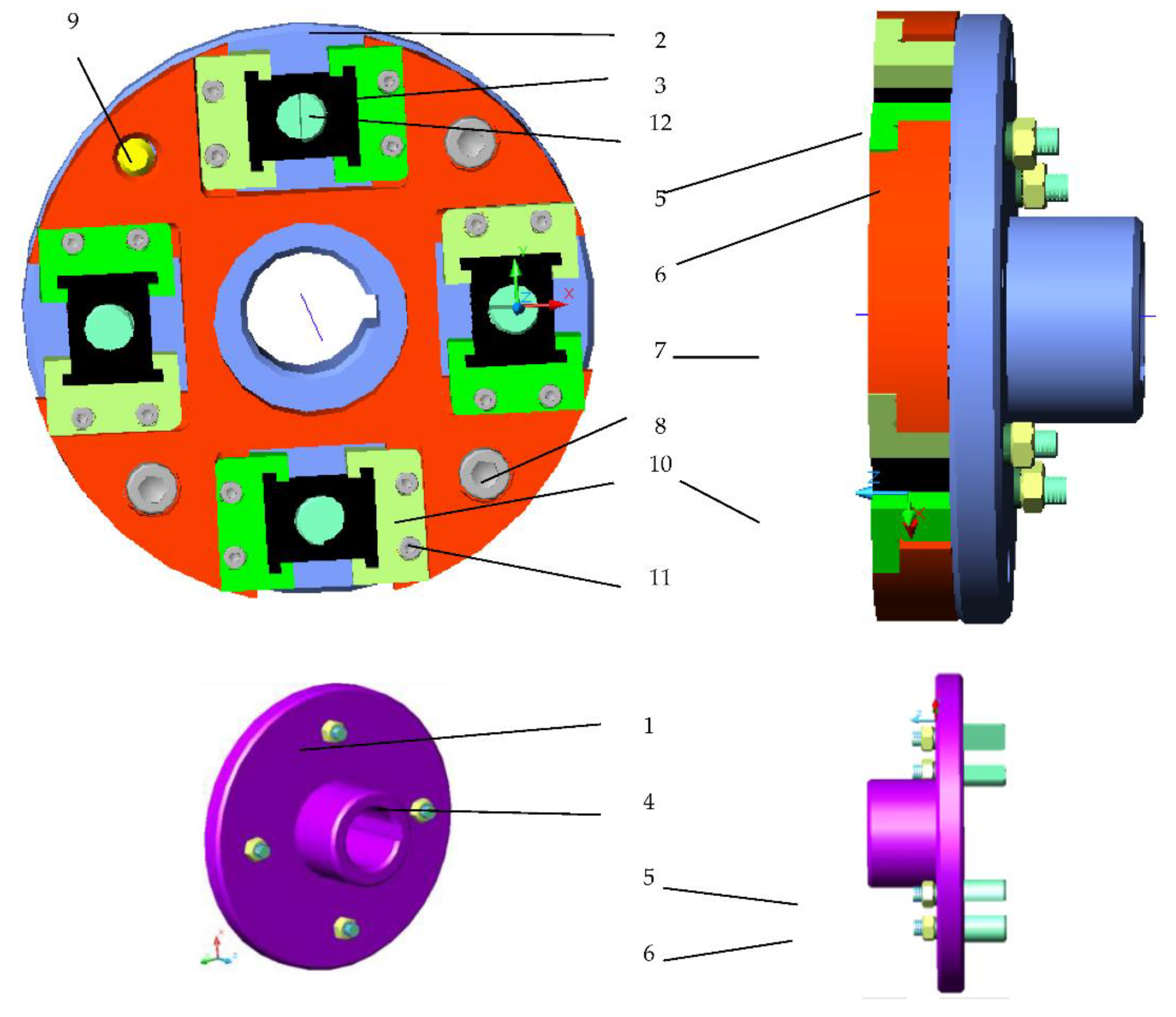
In the literature, there is no flexible coupling solution with milled bolts and non-metallic elements by type of coupling designed (
Figure 1). The novelty of this coupling consists of the existence of one intermediary disk which has four processed holes, the intermediary disk being mounted between two semi couplings. The disk is and fixed to the right half-coupling with screws and centered with the semi-coupling with one cylindrical pin of eight metallic plates fixed with one left and one right to each processed hole on the intermediate disc (there are four disk stakes arranged at 90 degrees). The nonmetallic elements from different qualities of rubber are mounted with bolts and with eight milled bolts, four on each semi-coupling. By using the milled bolts, four mounted on each half-coupling, the transmission of the movement and the torque in both directions are obtained. Each metal plate attaches to the intermediate disc by means of two screws.
In existing locations between two plates (there are four locations), a non-metallic element is mounted. Non-metallic rubber elements of different qualities are mounted in the space between two plates, thus there are four non-metallic elements mounted. At the same time, the non-metallic element is mounted on the bolts.
This is a new flexible coupling with bolts that differs from the classic solutions of flexible couplings with milled bolts and non-metallic elements by the existence of the intermediate disc, the existence and the form of non-metallic plates and of non-metallic elements that have various constructive forms that can be changed, and by the existence of the eight milled bolts, which are mounted/fixed with four on each half-coupling (
Figure 1). On each semi-coupling, four milled bolts are mounted, fixing each semi-coupling bolt by means of a nut and a Grower washer.
In this constructive variant, the bolts 4 and 12 are milled, and their number is eight, four on each semi-coupling. The contact between the milled faces of the bolts is about the length equal to the width of the non-metallic element 3 [
9].
The number of bolts mounted on each semi-coupling is four and equals the number of non-metallic elements 3 mounted between the metal plates 10 fixed to the intermediate disk 7, and this number is equal to the maximum number of milled holes on the intermediate disk so as not to endanger the strength of the milled disk and the allocators. The milled part of the bolts allows the transmission of the movement and the torque from one half-coupling to another. The two milled areas of two bolts (one on each half-coupling) come into contact (
Figure 1 on the width of the non-metallic element. There are four mounted milled bolts from a total of eight on each half-coupling; only four milled bolts work at a chosen direction of rotation.
The semi-couplings are approximately identical, the constructive differences consisting of the presence on the driven semi-coupling 2 at the level of diameter D
s, of four equidistant holes, three of them being threaded, for fixing by means of screws 8 the intermediate disk 7 of the driven semi-coupling 2, and of the fourth orifice for centering by means of the cylindrical pin 9 of the intermediate disc on the driven semi-coupling. The subassembly consists of the half-coupling (2), the milled bolts 12 fixed by the semi-coupling by means of the Grower washers 5 and the M8 nuts 6, the metal plates 10 fixed to the intermediate disc 7 by means of the screws 11 in the space between the plates and the non-metallic elements 3, which come into contact with the milled bolts that are fitted. The intermediate disk 7 is fixed to the semi-coupling driven 2 by means of the screws 8, the centering of the disk in relation to the intermediate disk being achieved by means of the cylindrical pin 9. In the coupling component, in the milled locations on the intermediate disc 7 are mounted four subassemblies plates 10, a non-metallic element 3, and screws 11, one in each milled location of the type shown in
Figure 1.
The non-metallic element has various shapes presented below in the form of the letter H. The foot of the letter H ensures fastening and centering in the places of the plates.
The non-metallic element 3 that is mounted between the plates is made of the same rubber quality. Non-metallic element 3 can be made of three rubber qualities (natural rubber, NR; butadiene rubber acrylonitrile, NBR; ethylene propylene diene rubber, EPDM. When designing the coupling, the influence of the shape of the non-metallic element and the quality of the rubber on the coupling performance were taken into account.
In the optimal design process of the flexible coupling with milled bolts and non-metallic elements, the following aspects were taken into account:
Driver machine (electric motor): characterized by engine power P(kW) and speed n (rot/min);
Maximum diameter of d (mm) shafts on which the semi-couplings are mounted;
Coupling gauge: L (mm)—length of coupling, De (mm)—exterior diameter of semi coupling;
Limits (minimum, maximum) of the torsion moment transmitted by coupling: Mtmin, Mtmax (Nmm);
Performing the functions characteristic of flexible couplings with non-metallic elements: transmission of rotational motion and torsion moment; taking over the position albeit deviations of the shafts; shock and vibration damping;
Safety in operation: superior mechanical strength of the fastening screws of the two semi-couples of the cylindrical centering stud;
Economic requirements: execution processes and means of economic processing;
Establishment of technology for semi-manufactured: non-metallic elements made by vulcanization; semi-couplings are obtained by free forging or molding; the intermediate disc is obtained by free forging; bolts are made of round laminated steel; metal plates are made of square laminated steel;
Maintenance conditions: simple maintenance; visual control at each use;
Ergonomic costs and requirements: simple constructive form; minimum material consumption, cost per minimum product.
The main parameter resulting from the characteristic of the flexible couplings is the torque. Another important parameter is the rigidity, which represents the dependence of the relative rotation angle of the half-couplings, depending on the value of the torque .
The flexible coupling with milled bolts and non-metallic elements is characterized by damping capacity and rigidity. The existence of the flexible coupling in the mechanical systems favorably influences their behavior at oscillating loads, frequently encountered in operation, high values of the degree of damping leading to a quieter operation of the mechanical systems equipped with such a coupling. In this constructive version, by applying at the input of a torque in the direction indicated by the continuous arrow (I) (see
Figure 1), the torque is transmitted from entry driver semi-coupling 1, by shape, through the milled bolts 4 to the milled bolts 12, fixed rigidly by the semi-coupling 2, in this sense, the coupling becoming rigid. In the direction of rotation indicated by the interrupted arrow (II), the milled bolts 4 act on the elastic element 3 of different constructive forms, compressing it in the direction of movement.
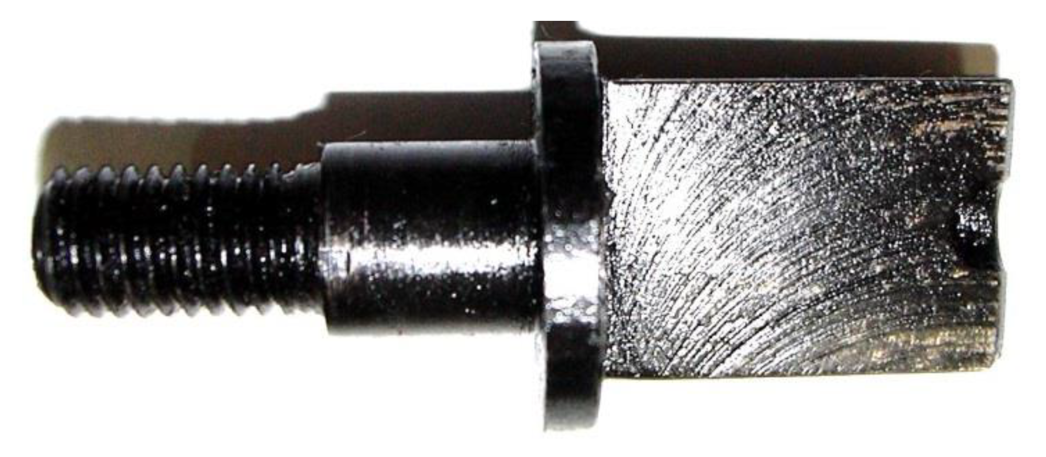
Figure 2 presents the 3D model of the constructive form of the milled bolt realized in Autodesk Mechanical Desktop 6 Power Pack [
29] and Catia V5 [
30]. The milled bolts 4 and 12 are fixed to the semi-coupled leading 1 and driven 2 by means of Grower washers and nuts that prevent the bolts from breaking. The cylindrical area of the bolt with a diameter greater than the diameter of the milled area is intended to reduce the stresses concentrators and break the bolt at the passage of diameter from the diameter of the milled area to the diameter of the cylindrical zone to the right of the threaded area. The cylindrical area with the largest diameter in the bolt component represents a shoulder, stopping on the milled end of the bolt, which is mounted in the opposite direction. The installation of the milled bolts 4 of the driver semi-coupling 1 is done easily. From right to left, the bolts are inserted into the bores processed in the driver semi-coupling 1, then Grower washers 5 and nuts 6 are mounted, and the nuts are tightened. The installation of the milled bolts 12 of the driven semi-coupling 2 (the right half-coupling,
Figure 1) is easy as well. From left to right, the bolts are inserted into the handles processed in the semi-coupled driven 2, and then the Grower washers 5 and the nuts 6 are mounted, and the nuts are squeezed against the unraveling of the bolts.
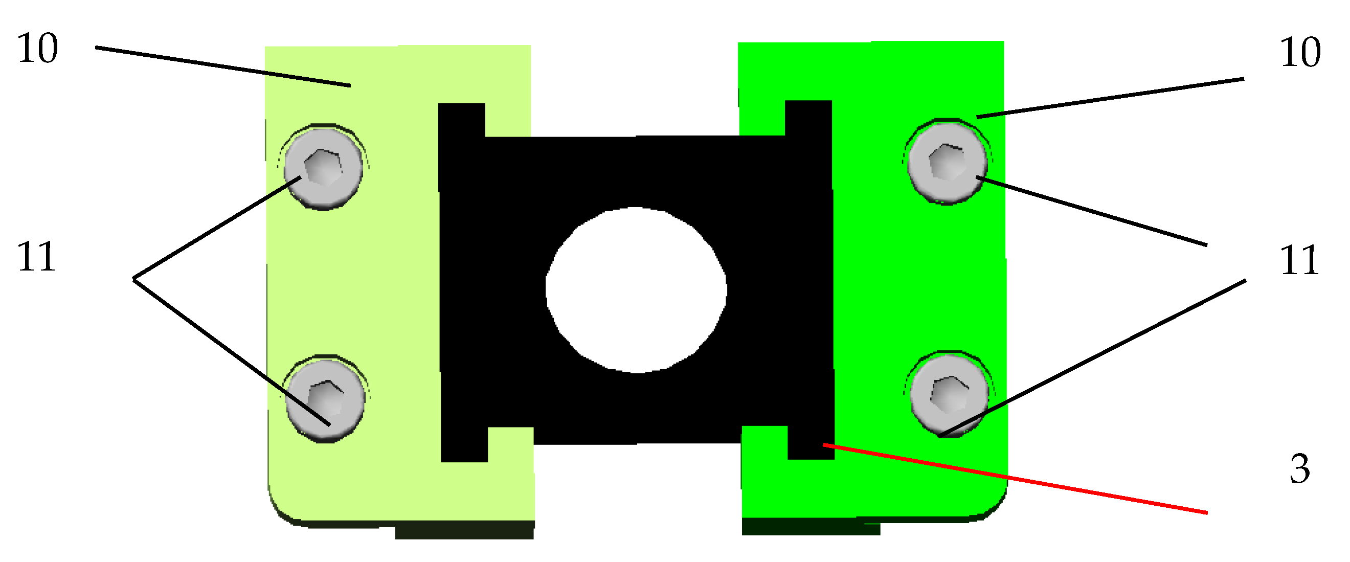
Figure 3 presents the 3D model of forms of plates on the left side and on the right side. Each plate has a milled channel, in which one end of the non-metallic element is mounted, while the other end of the non-metallic element is mounted in the processed channel in the plate fixed on the opposite side of each milled slot located on the intermediate disk.
Figure 4 shows the subassembly consisting of plates 10, non-metallic element 3 mounted between those two plates, and screws 11, the subassembly being part of the constructive variant of the prototype. For fixing the metal plate 10 of the intermediate disc 7, two screws 11 are sufficient for low execution costs for the plate and the intermediate disc, saving material and reducing the weight of the coupling.
Figure 5 shows the subassembly consisting of the semi-coupling of the driver 1, the milled bolts 4, the Grower 5 washers, and the nuts 6, the subassembly being part of the constructive variant of the prototype. Semi-coupling drive 1 input transmits the torsion moment from the electric motor to the milled bolts 4 fixed by this semi-coupling.
The milled bolts 4 and 12, the metallic elements 10, the intermediary disc 7, and the semi couplings 1 and 2 can be made from improved OLC 45 steel (improved quality rolled steel brand with 0.45% carbon content). The mechanical characteristics of the improved OLC 45 (equivalent steel is C 45) steel are: density = 8.31 g/cm3, Young’s modulus = 200 GPa, Poisson’s ratio = 0.287.
The coupling was modeled with Computer Aid Design (CAD) in the Autodesk Mechanical Desktop 6 Power Pack and Catia V5.
The non-metallic element is required for crushing and traction. The bolt is required for bending.
3. Calculus Element, Execution and Testing of Flexible Coupling with Milled Bolts and Non-Metallic Elements
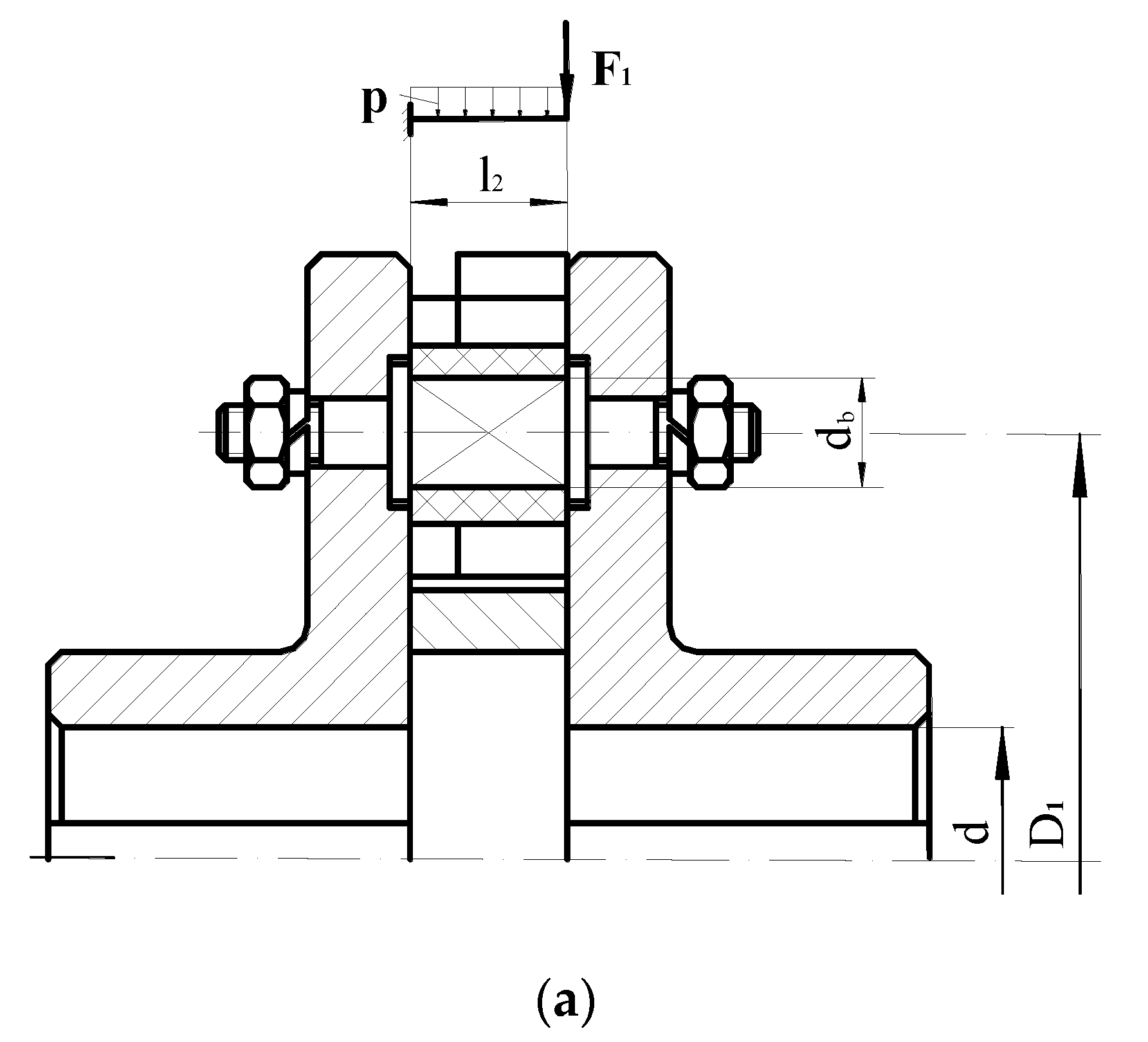
The numerical modeling of the performances of the designed coupling is performed on the basis of a calculation scheme, this being presented in
Figure 4 [
9].
According to the assembly of
Figure 4a, the bolt is an integral part of the semi-coupling 1. Non-metallic elastic elements are incompressible, as they can change their shape, but they do not change their volume to a large extent.
Two hypotheses are used in the calculus:
During operation, other additional loads act on the coupling elements, such as: inertia loads, which appear in the non-stationary operating mode of the transmission equipped with coupling; shock and vibratory loads, which occur in both non-stationary and stationary operating modes; loads due to the elements of the couplings. The magnitude of the load acting on the couplings depends on: the characteristic of the motor car, the operating mode of the driven car, the influence of the coupling on the moment of inertia, the rigidity, and the vibration behavior of the kinematic chain.
Due to the fact that it is not possible to know exactly the variation of the torque over the entire operating time, the coupling calculation is performed at an imposed value of calculation torque
Mtc. Taking into account the additional loads that may occur at installation or during operation, the so-called torsion moment of calculation
Mtc, is calculated with the formula:
where
KS is a safety factor experimentally obtained and offered by literature [
1],
Mtn is nominal torque calculated using the power of the electric motor
P and its corresponding rotation speed
n, with the relation
[
9].
Assuming that all bolts are loaded evenly and their number is
z, the force loading a bolt is
The crush check is performed at the bolt level. Assuming the uniform distribution of pressures along the generator and in section, the crushing between the bolt and the elastic element is determined by the relation [
12].
where:
is the crushing surface,
is the bolt diameter,
is the length on which the crushing occurs (
,
being the thickness of the non-metallic element),
is the permissible crushing resistance (
), and
is the calculation torque [
9,
11].
Applying a traction, the stress is given by [
12]:
where:
At is the section area (
At = (
h2 −
db)
b—for the shape of
Figure 2),
σat = 1.5 MPa from [
9].
The bending stress is
where
,
MPa—for bolt realized from improved OLC 45 steel. The values obtained applying Equation (5) is
.
Angle of relative rotation of those semi couplings is offered by:
The rigidity is obtained by
The non-metallic element was studied with the finite element method(FEM) [
30,
31]. The deformation of the non-metallic element is presented in
Figure 5. Von Mises stresses appearing in the non-metallic element are presented in
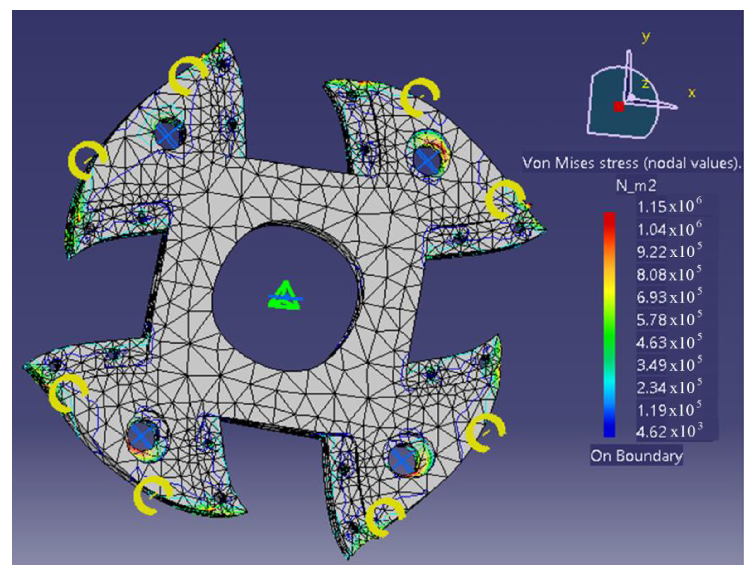
Figure 6. This numerical has been used to determine the elastic response of the components of the proposed coupling. A total of 13,482 octree (parabolic tetrahedron) discretization elements were used. The FEM analysis shows a non-metallic element deformation of 1.76 mm. The experimental determinations performed in static regime gave a maximum deformation of the non-metallic element of 1.77 mm.
The maximum Von Mises stresses are presented in
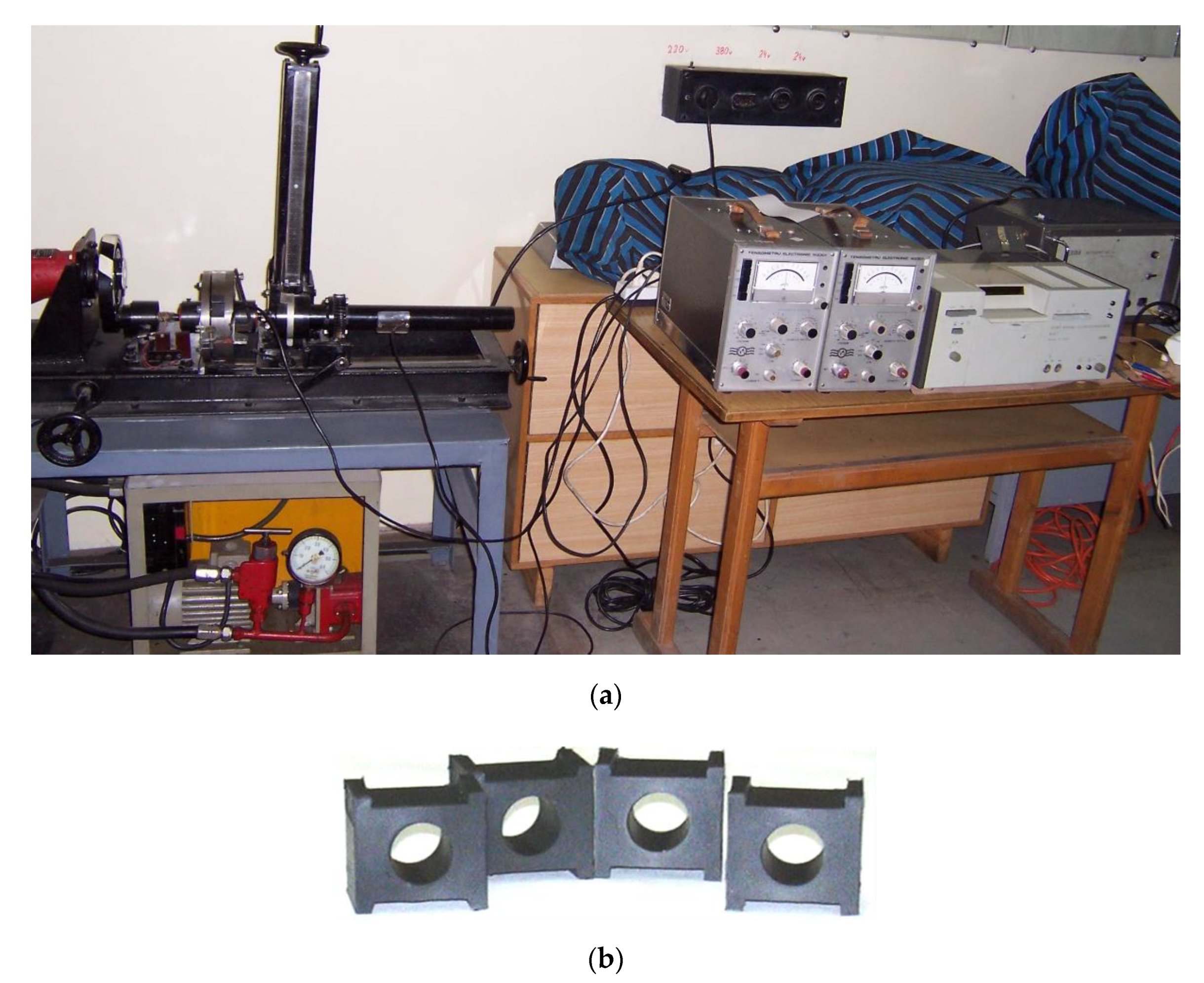
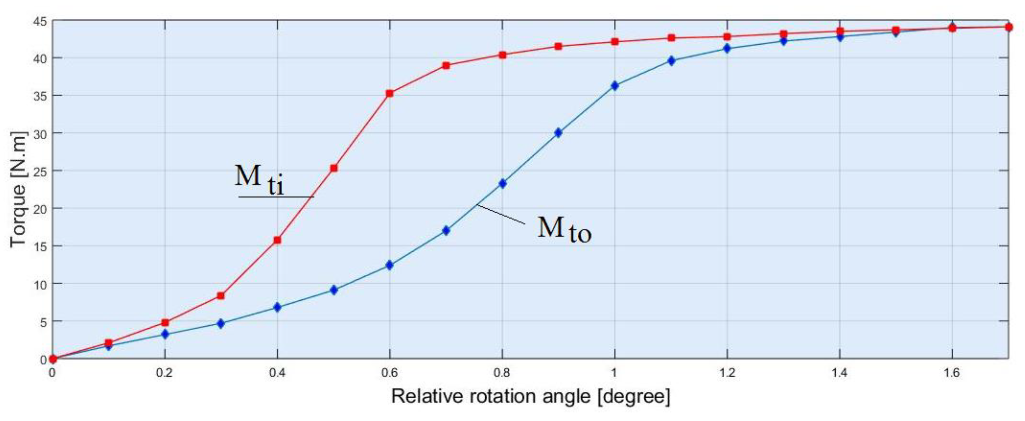
Figure 7. The results of the experimental tests of the coupling containing the non-metallic element 3 made of natural rubber are presented in the following figure. The static characteristic can be seen (when the input-output shafts are collinear) with a hysteresis loop of the non-metallic element. The nonlinear character of the characteristic of the non-metallic element exists both for loading and for unloading. The experimental setup made to perform the measurement is presented in
Figure 8.
Curve 1 from
Figure 9 presents variation of torque of input shaft in time. Curve 2 in the same figure presents variation of output torque of output shaft during unloading. M
ti represents the input torque and M
to the output torque.
The shock takes place by deforming the non-metallic elastic intermediate element, which transforms the shock energy into mechanical deformation work Le (the area under the load characteristic). Part of this energy (the area between the charging and the discharging characteristics) is transformed into heat, representing the mechanical friction work Lf in the coupling. In non-metallic intermediate elements, friction takes place inside the elastic element (internal friction). From calculus results, mechanical deformation work = 211.94 J. The high values of the shock absorption capacity lead to the quiet operation of the transmission equipped with such a coupling, even to oscillating loads. The flexible coupling with damping also improves the behavior in vibrational mode.
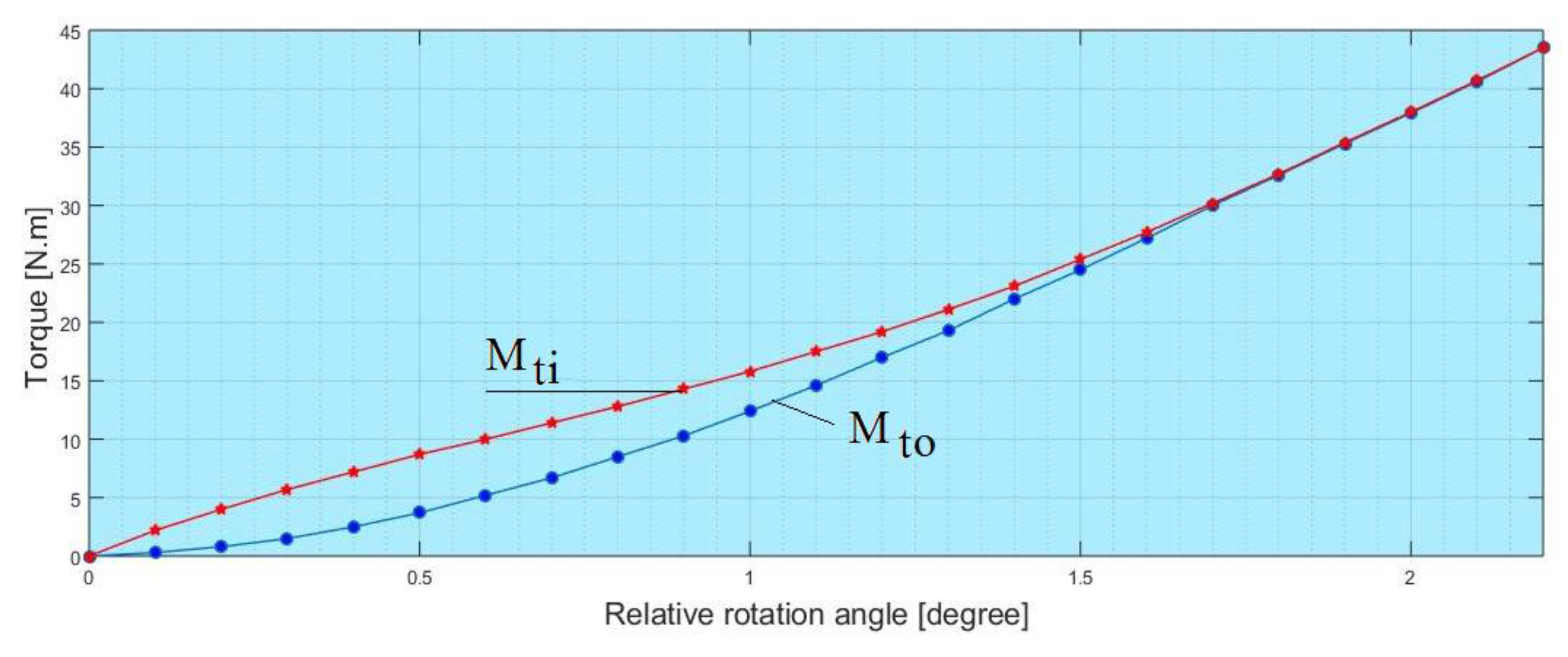
Figure 10 shows the experimental torque at the input and the output shaft as well as for the attenuation factor of the constructive variant of the prototype tested in dynamic mode with the input shafts (collinearly output). The damping capacity of torsion shocks is the characteristic of flexible couplings to convert some of their energy into heat, the rest being converted into deformation energy, which will be returned to the system after the shock action ceases.
Figure 10 shows the variation of the relative rotation angle between the semi-coupled and the torsion moment at the dynamic output shaft, the data recording speed at the oscillograph being 100 mm/s in time of 1 s. In this figure can be seen the dynamic characteristic with a hysteresis loop of the non-metallic element. The hysteresis loop is smaller and more attenuated in dynamic mode. In dynamic behavior, the shocks and the vibrations are higher, and the coupling damps these shocks and vibrations very well through the non-metallic elements. The relative rotation angle between the dynamic couplings is 2.25°, and the input the output shafts have collinearity. In dynamic mode, the coupling must also take over the overloads that appear during starting as well as the shocks that may occur during the operation of the system equipped with coupling. For
Figure 11, from calculus results, a mechanical deformation work
= 394.11 J.
5. Conclusions
The following criteria must be taken into account when designing such a coupling: the coupling must take axial, radial, and/or angular deviations; the relative movement between the semi-couplings to be done without shocks; the coupling must have a low rigidity; feature to have an increasing slope and high damping capacity; changing the non-metallic elastic elements to achieve the modification of the coupling elasticity; in case of damage to a non-metallic element, the coupling can continue to operate; destroyed elastic elements can be easily replaced; the component elements of the coupling must not have protrusions/roughness, thus increasing the safety in operation.
The study permits us to draw the following conclusions:
the coupling has the possibility to transmit the torque in any direction;
the proposed solution of coupling ensures compensation of radial and angular deviations;
in the case of small deformations, E constant, and taking into account the other constants in the expression of rigidity, it appears that the characteristic of the coupling is linear;
the calculation algorithm of the flexible coupling with milled bolts and non-metallic elements presented is original and based on the hypothesis made in the paper;
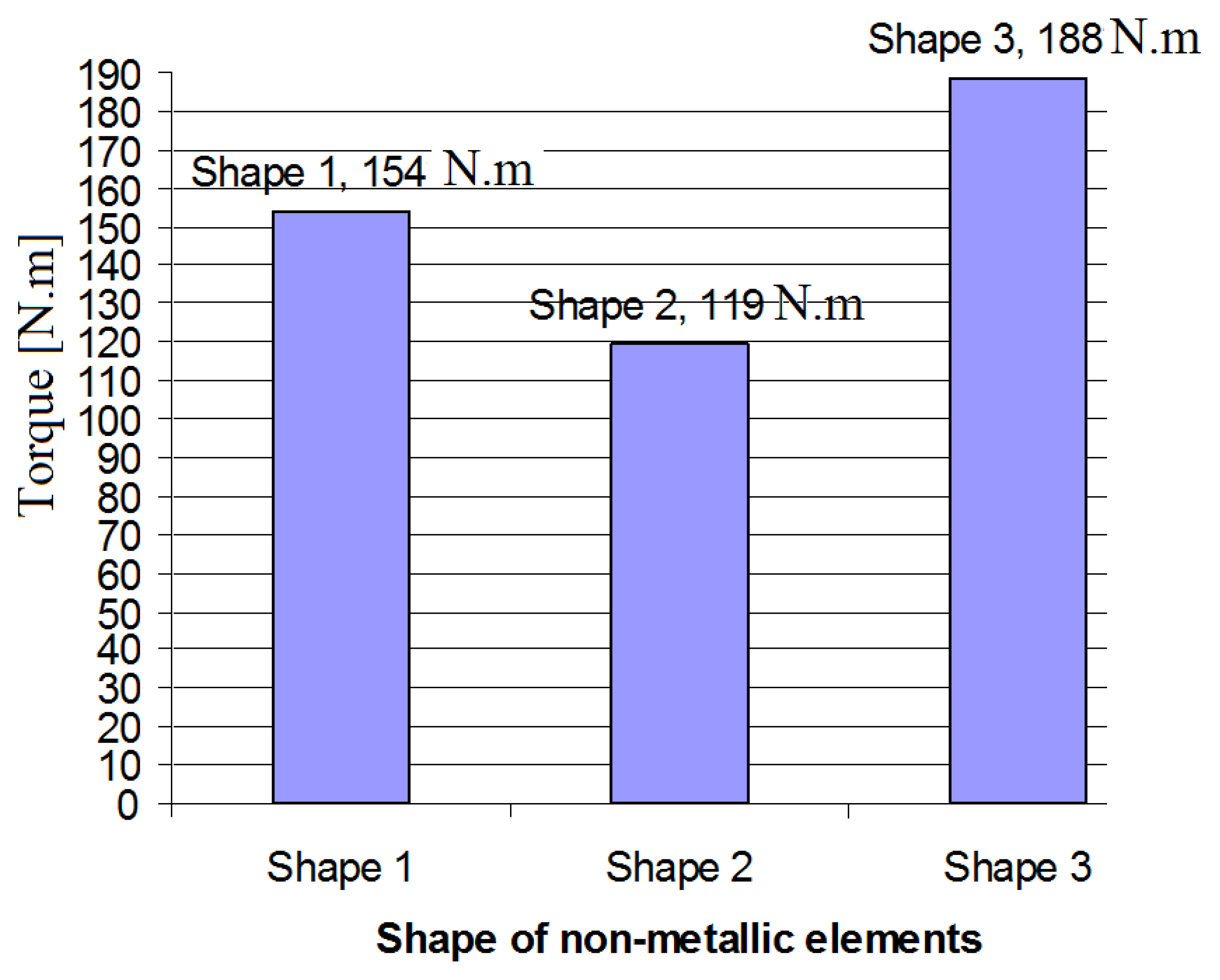
the maximum moment that can be transmitted by the coupling is 188.232 N∙m for the third form of the non-metallic element;
when exceeding the torsion moment determined from the tensile strength condition of the non-metallic element, the elastic element will break, thus the coupling can also perform the safety function (load limitation);
from the calculations performed, it results that the rigidity of the coupling is small when the non-metallic elements are made of natural rubber (NR);
the rigidity of the coupling is high when the non-metallic elements are made of ethylene propylene diene rubber (EPDM);
this type of coupling can be used in mechanical engineering, lifting installations, or in electromechanical systems;
the coupling designed and executed has a simple construction, small size, and a low cost compared to the classic ones with non-metallic elements and bolts.
The main objective was the level of performance of the coupling, namely the torque of being transmitted by the coupling. Experimental determinations were made in different cases by loading and unloading. Another objective was to carry out tests in different modes (static and dynamic, respectively) taking into account the situation that the two input and output shafts are collinear. From the point of view of functional performance (the torque transmitted by coupling to a load-discharge cycle and the torque to input shaft I and output shaft II, respectively), the coupling performed well, the values obtained experimentally being close to the theoretical ones.
The tested construction variant has a very good shock and vibration attenuation factor of up to 9%.
Figure 9 and
Figure 11 show the non-linear characteristic of non-metallic elements at loading and unloading, which means that the flexible coupling with milled bolts and non-metallic elements has the non-linear characteristic, and the coupling is with variable rigidity. Damping occurs if there is a difference between the elastic loading characteristic and the elastic unloading characteristic of the coupling. The hysteresis loop is smaller and more attenuated in dynamic mode. In dynamic mode, the shocks and the vibrations are higher, and the coupling damps these shocks and vibrations very well through the non-metallic elements.
From the dynamic variation of the torsion moment at the output shaft according to the relative angle of rotation between the two semi-couples it can be observed that the non-metallic element has a negligible hysteretic loss, on a small portion of the discharge characteristic practically coinciding with the loading. Note the non-linear nature of the non-metallic element feature when loading and unloading.
