Article

Convective Heat/Mass Transfer Analysis on Johnson-Segalman Fluid in a Symmetric Curved Channel with Peristalsis: Engineering Applications

1
Department of Basic Sciences, Preparatory Year Deanship, King Faisal University, Al-Ahsa 31982, Saudi Arabia
2
Department of Mathematics, Faculty of Science, University of Ha’il, Ha’il 81481, Saudi Arabia
3
Department of Mathematics, Quaid-I-Azam University 45320, Islamabad 44000, Pakistan
*
Authors to whom correspondence should be addressed.
Symmetry 2020, 12(9), 1475; https://doi.org/10.3390/sym12091475
Submission received: 19 August 2020 / Revised: 1 September 2020 / Accepted: 4 September 2020 / Published: 8 September 2020
(This article belongs to the Special Issue Recent Advances in Mathematical Aspect in Engineering)

Abstract

:
The peristaltic flow of Johnson–Segalman fluid in a symmetric curved channel with convective conditions and flexible walls is addressed in this article. The channel walls are considered to be compliant. The main objective of this article is to discuss the effects of curvilinear of the channel and heat/mass convection through boundary conditions. The constitutive equations for Johnson–Segalman fluid are modeled and analyzed under lubrication approach. The stream function, temperature, and concentration profiles are derived. The analytical solutions are obtained by using regular perturbation method for significant number, named as Weissenberg number. The influence of the parameter values on the physical level of interest is outlined and discussed. Comparison is made between Jhonson-Segalman and Newtonian fluid. It is concluded that the axial velocity of Jhonson-Segalman fluid is substantially higher than that of Newtonian fluid.

1. Introduction

The researchers have great interest in peristaltic transport of fluids due to immense applications in physiology, biomedical engineering andnindustry. Such motion is caused by a wave of expansion and contraction that propagates along the channel walls. Peristalsis includes the passage of urine from kidney to bladder, swallowing of food through oesophagus, the movement of chyme in the gastrointestinal tract, the vasomotion of small blood vessels, and many others. Blood pumps in the dialysis and heart lung machine operate on the principle of peristaltic action. The roller and finger pumps also operate according to this mechanism. In the nuclear industry, toxic materials can be moved through such a system in order to avoid contaminants from the outside area. Pioneering researches on the topic are presented by Latham [1], Shapiro et al. [2], and Yin and Fung [3]. Currently, abundant literature exists on peristaltic flows of viscous and non-Newtonian fluids under different aspects (see [4,5,6,7,8,9,10,11,12,13,14,15,16,17,18,19] and several studies there in). Amongst the several models of non-Newtonian material there is one fluid model that can describe the “spurt” phenomenon. It is subclass of integral type non-Newtonian material and is known as the Johnson–Segalman (JS) fluid. The phrase “spurt” is being used to characterize a significant volume rise to a slight rise in the moving pressure gradient. The contributions of Hayat et al. [20,21,22] are fundamental in this direction. Elshahed and Haroun [23] investigated the peristaltically moving Johnson–Segalman fluid together with the impact of the magnetism. Wang et al. [24] explored the peristalsis of the Johnson–Segalman fluid across a non-rigid tube. In reality, the configuration of the most physiological tubes and glandular ducts is curved. In this context, the effect of curvature appears to be meaningful. This fact gives great motivation to study peristaltic flow through curved channels. In the first place, Sato et al. [25] addressed the two-dimensional peristaltic transport of viscous liquid inside a curved channel. Ali et al. [26] revisited the analysis of Sato et al. [25] in a wave frame. Some more interesting studies for peristalsis in a curved channel can be consulted through [27,28,29,30,31].
The effect of heat transfer has vast applications in food processing, dilation of blood vessels, heat conduction in tissues, and its convection due to blood flow from the pores of the tissues. The impact of both heat and mass transfer plays an essential part in spreading of chemical pollutants in saturated soil, underground disposal of nuclear waste, thermal insulation, enhanced oil recovery, etc. The effects of mass transfer arose in diffusion, combustion, and distillation processes, and in many other industrial processes. Convective heat transfer through boundary conditions is used in systems, such as steam turbines, nuclear power stations, thermal energy storage, etc. In this context, Hina and Hayat [32] examined the effects of heat/mass transfer on Johnson-Segalman liquid inducing peristaltic movement in a compliant curved channel. Mehmood et al. [33], Hayat et al. [34] and Riaz et al. [35] analyzed the characteristics of heat flux in peristaltic transport with/without compliant walls. Hayat et al. [36,37,38,39] conducted an analysis of non-Newtonian fluids with peristalsis in the presence of convective constraints. Yasmin et al. [40] discussed the effects of convective conditions in peristalsis of Johnson–Segalman fluid in an asymmetric channel.
It is noted that the peristalsis of non-Newtonian fluid in a curved channel with convective mass transfer conditions at the walls is not addressed so far. Even such analysis is not carried out for viscous fluids. The current research paper varies from the existing results in terms of convective boundary conditions. The key focus of this paper is the implementation of a novel definition of convective heat and mass transfer conditions in the theory of Johnson–Segalman fluid transferred via a peristaltic motion across a curved channel. Hence, in this attempt, the convective conditions for both heat and mass transfer are considered. An incompressible Johnson–Segalman fluid is considered in a curved channel. The set of solutions for the small value of Weissenberg number are developed. The obtained results are visualized and thoroughly analyzed. Impacts reflecting the influence of pertinent parameters are pointed out physically.

2. Problem Formulation

We anticipate the peristaltic transport of the incompressible Johnson–Segalman fluid in a symmetric curved half-width ( d 1 ) channel clasped in a circular pattern with center O and radius R * (see Figure 1 and Ref. [32]).
The flow in the channel is stimulated by small amplitude sinusoidal waves that travel along the compliant walls. The axial direction of the flow is x and r is radial direction. Here, v and u are the velocity vector components in the radial and axial directions, respectively. The wave shapes at channel walls are considered symmetric and given by
r = ± η ( x , t ) = ± d 1 + a sin 2 π λ ( x c t ) ,
where c is the wave speed and λ is the wavelength, respectively.
The continuity and momentum equations governing the flow can be written as [32]:
[ ( r + R * ) v ] r + R * u x = 0 ,
ρ v t + v v r + R * u r + R * v x u 2 r + R * = p r + 1 r + R * r [ ( r + R * ) τ r r ] + R * r + R * τ x r x τ x x r + R * ,
ρ u t + v u r + R * u r + R * u x + u v r + R * = R * r + R * p x + 1 ( r + R * ) 2 r [ ( r + R * ) 2 τ r x ] + R * r + R * τ x x x .
The equations for energy and concentration [32] are given by
ρ C p T t + v T r + R * u r + R * T x = κ 2 T x 2 R * r + R * 2 + 1 r + R * T r + 2 T r 2 + ( S r r S x x ) v r + S x r u r + R * r + R * v x u r + R * ,
C t + v C r + R * u r + R * C x = D 2 C x 2 R * r + R * 2 + 1 r + R * C r + 2 C r 2 + D K T T m 2 T r 2 + 1 r + R * T r + R * r + R * 2 2 T x 2 .
For the Johnson-Segalman fluid, the stress tensor ø is
ø = 2 μ D + S ,
in which the extra stress tensor S needs to satisfy the relationship
S + m d S d t + S ( W ξ D ) + ( W ξ D ) T S = 2 η 1 D ,
where
D = [ ( g r a d V ) T + g r a d V ] 2 ,
W = [ g r a d V ( g r a d V ) T ] 2 .
The relations listed above produce the following equations:
S r r + m d S r r d t 2 u S r x r + R * + S r x ( 1 ξ ) u r 1 + ξ r + R * [ R * v x u ] 2 ξ S r r v r = 2 η 1 v r ,
S r x + m d S r x d t + m u ( S r r S x x ) r + R * + m S x x 2 ( 1 ξ ) u r 1 + ξ r + R * R * v x u + m S r r 2 1 ξ r + R * R * v x u ( 1 + ξ ) u r = η 1 u r + R * r + R * v x u r + R * ,
S x x + m d S x x d t + 2 u S r x r + R * S r x ( 1 + ξ ) u r 1 ξ r + R * R * v x u + 2 ξ S x x v r = 2 η 1 v r ,
where d d t = t + v r + R * u r + R * x represents the material derivative with respect to time, ρ denotes the fluid density, κ the thermal conductivity of fluid, W and D skew-symmetric and symmetrical parts of the gradient of velocity, ξ the slip parameter, C p the fluid specific heat, T and C are the fluid temperature and concentration, respectively, the thermal diffusion ratio is K T , D the mass diffusivity coefficient, T m represents the mean/average temperature, μ and η 1 the viscosities, and m the relaxation time.
The appropriate boundary conditions are
u = 0 at r = ± η ,
k T r = h 1 ( T T 0 ) at r = + η ,
k T r = h 2 ( T 0 T ) at r = η ,
D C r = h 3 ( C C 0 ) at r = + η ,
D C r = h 4 ( C 0 C ) at r = η ,
R * [ τ 3 x 3 + m 1 3 x t 2 + d 2 t x ] η = 1 r + R * r { ( r + R * ) 2 τ r x } + R * τ x x x ρ ( r + R * ) u t + v u r + R * u r + R * u x + u v r + R * at r = ± η .
Here, the pressure, the time, the fluid density, and the curvature parameters are p, t, ρ , and R * , respectively, T 0 and C 0 the ambient temperature and concentration, h 1 and h 2 the coefficients of heat transfer at upper and lower walls, h 3 and h 4 the coefficients of mass transfer at upper and lower walls, S r r , S r x , S x r and S x x the components of the extra stress tensor S , τ the elastic tension, d the viscous damping coefficient, and m 1 the mass per unit area. Equation (10) is the no slip condition for velocity profile. Equations (11) and (12) are the convective boundary conditions for heat transfer. Analogues to the convective heat transfer at the boundary, we also use the mixed condition for the mass transfer as well (i.e., Equations (13) and (14)).
Employing the aforementioned dimensionless variables
x * = x λ , r * = r d 1 , u * = u c , v * = v c , Ψ * = Ψ c d 1 , t * = c t λ , η * = η d 1 , k = R * d 1 , p * = d 1 2 p c λ ( μ + η 1 ) , ε = a d , δ = d 1 λ , θ = T T 0 T 0 , ϕ = C C 0 C 0 , S i j * = d 1 S i j c η 1 , W e = m c d 1 ,
Equations (7)–(9) become
2 v r = S r r + W e δ t + v r + u k δ r + k x S r r 2 u S r x r + k 2 ξ S r r v r + W e S r x 1 ξ u r 1 + ξ r + k k δ v x u ,
u r + k δ r + k v x u r + k = S r x + W e δ t + v r + u k δ r + k x S r x + u ( S r r S x x ) r + k + W e S r r 2 1 ξ r + k k δ v x u 1 + ξ u r + W e S x x 2 1 ξ u r 1 + ξ r + k k δ v x u ,
2 v r = S x x + W e δ t + v r + u k δ r + k x S x x + 2 u S r x r + k 2 ξ S x x v r + W e S r x 1 ξ r + k k δ v x u 1 + ξ u r ,
and Equations (4)–(6) are reduced to
Re δ δ v t + v v r + v x k δ u r + k u 2 r + k = η 1 + μ η 1 p r + 4 δ μ η 1 ( r + k ) v r + k δ 3 r + k S r x x + δ S r r r + δ ( S r r S x x ) r + k + δ μ η 1 2 v r 2 + δ 2 k μ η 1 ( r + k ) × x u r + k δ r + k v x u r + k ,
Re δ u t + v u r + k δ u r + k u x u v r + k = η 1 + μ η 1 ( r + k ) p x + 2 S r x r + k + S r x r + k δ r + k S x x x 2 k δ μ r + k η 1 × 2 v r x + μ η 1 x u r + k δ r + k v x u r + k + δ μ η 1 2 v r 2 + δ 2 k μ η 1 ( r + k ) × r u r + k δ r + k v x u r + k + 2 μ η 1 ( r + k ) u r + v x k δ r + k u r + k ,
Re δ θ t + v θ r + θ x k δ u r + k = E S x r u r + k δ r + k v x u r + k + ( S r r S x x ) v r + 1 Pr 2 θ r 2 + 1 r + k θ r + δ 2 2 θ x 2 ,
Re δ ϕ t + v ϕ r + k δ u r + k ϕ x = 1 S c 2 ϕ r 2 + 1 r + k ϕ r + δ 2 2 ϕ x 2 + S r 2 θ r 2 + 1 r + k θ r + δ 2 2 θ x 2 ,
with
u = 0 at r = ± η ,
θ r + B i 1 θ = 0 at r = + η ,
θ r B i 2 θ = 0 at r = η ,
φ r + B i 3 ϕ = 0 at r = + η ,
φ r B i 4 ϕ = 0 at r = η ,
k [ E 1 3 x 3 + E 2 3 x t 2 + E 3 2 t x ] η = η 1 ( r + k ) η 1 + μ r u r + k δ r + k v x u r + k 2 k δ r + k 2 v r x R e μ ( r + k ) η 1 + μ δ u t + v u r + k δ u r + k u x + u v r + k + η 1 ( r + k ) η 1 + μ S r x r + S r x x k δ r + k + 2 S r x r + k + 2 μ ( η 1 + μ ) u r + v x k δ r + k u r + k at r ± η .
Defining the stream function ψ ( x , r , t ) by
u = ψ r , v = δ k r + k ψ x ,
Equation (2) is automatically satisfied and Equations (16)–(28) subject to lubrication approach become
0 = S r r + W e S r x 1 ξ ψ r r 1 + ξ r + k ψ r + 2 ψ r r + k ,
ψ r r + ψ r r + k = S r x W e ψ r ( S r r S x x ) r + k + W e S r r 2 1 ξ r + k ψ r + 1 + ξ ψ r r W e S x x 2 1 + ξ r + k ψ r + 1 ξ ψ r r ,
0 = S x x + W e S r x 1 + ξ ψ r r + 1 ξ r + k ψ r 2 ψ r r + k ,
p r = 0 ,
k ( η 1 + μ ) η 1 r + k p x + S r x r + 2 S r x r + k + μ η 1 r ψ r r + ψ r r + k + 2 μ η 1 r + k ψ r r + ψ r r + k = 0 ,
2 r 2 + 1 k + r r θ = B r S r x ψ r r + ψ r k + r ,
2 r 2 + 1 k + r r ϕ = S c S r 2 r 2 + 1 k + r r θ ,
ψ r = 0 a t r = ± η = ± 1 + ε sin 2 π ( x t ) ,
θ r + B i 1 θ = 0 at r = + η ,
θ r B i 2 θ = 0 at r = η ,
φ r + B i 3 ϕ = 0 at r = + η ,
φ r B i 4 ϕ = 0 at r = η ,
k E 1 3 x 3 + E 2 3 x t 2 + E 3 2 x t η = η 1 ( r + k ) η 1 + μ μ η 1 r ψ r r + ψ r k + r + S r x r + 2 S r x r + k + 2 μ η 1 + μ ψ r r + ψ r r + k at r = ± η ,
where the amplitude ratio is represented by ϵ ( = a / d 1 ) , δ ( = d 1 / λ ) is the wave number, the dimensionless curvature parameter is k, E 1 = τ d 1 3 λ 3 η 1 c , E 2 = m 1 c d 1 3 λ 3 η 1 c , E 3 = d d 1 3 λ 2 η 1 the non-dimensional elasticity parameters, R e = c ρ d 1 η 1 λ 2 the Reynolds number, W e = m c / d 1 the Weissenberg number, the Prandtl number is denoted by P r = μ C p / κ , the Eckert number is E = c 2 / C p T 0 , the Schmidt numbers is S c = μ / ρ D , the Soret number is S r ( = ρ T 0 D K T / μ T m C 0 ) , E P r = B r is the Brinkman number, and B i 1 = h 1 d / k , B i 2 = h 2 d / k , B i 3 = h 3 d / D and B i 4 = h 4 d / D the Biot numbers for heat/mass transfer.
From Equations (30)–(32), one can get
S r x = ψ r r + ψ r r + k 1 + W e 2 1 ξ 2 ψ r r + ψ r r + k 2 1 .
Additionally, Equations (33) and (34) give
( r + k ) 2 S r x r 2 + 3 S r x r + ( k + r ) μ η 1 2 r 2 ψ r r + ψ r r + k + 3 μ η 1 r ψ r r + ψ r k + r = 0 .
Heat transfer coefficient at the wall is defined by
Z = η x θ y ( η ) .

3. Method of Solution

We have used the standard perturbation approach relying on a small parameter to solve the strictly nonlinear differential equations, because the exact solution is not achievable. This approach is helpful in finding an approximate solution to the problem, beginning with an exact solution to a similar and simplified problem. This approach is more efficient, as it provides a solution in the form of a converging series. In order to find the series solution of the problem, we expand ψ , p and S r x in terms of small parameter W e 2 . Therefore, we can write the flow quantities, as follows:
ψ = ψ 0 + W e 2 ψ 1 + ,
S r x = S 0 r x + W e 2 S 1 r x + ,
S r r = S 0 r r + W e 2 S 1 r r + ,
S x x = S 0 x x + W e 2 S 1 x x + ,
θ = θ 0 + W e 2 θ 1 + ,
ϕ = ϕ 0 + W e 2 ϕ 1 + ,
Z = Z 0 + W e 2 Z 1 + .

4. Results

4.1. Zeroth Order System

Using Equations (46)–(52) into Equations (35)–(45) and then equating the coefficients of W e 0 we have
( k + r ) 2 r 2 ψ 0 r r + ψ 0 r k + r + 3 r ψ 0 r r + ψ 0 r k + r = 0 ,
2 r 2 + 1 k + r r θ 0 = B r S 0 r x ψ 0 r r + ψ 0 r k + r ,
2 r 2 + 1 k + r r ϕ 0 = S c S r 2 r 2 + 1 k + r r θ 0
ψ 0 r = 0 , at r = ± η ,
θ 0 r + B i 1 θ 0 = 0 at r = + η ,
θ 0 r B i 2 θ 0 = 0 at r = η ,
φ 0 r + B i 3 ϕ 0 = 0 at r = + η ,
φ 0 r B i 4 ϕ 0 = 0 at r = η ,
k E 1 3 η x 3 + E 2 3 η x t 2 + E 3 2 η x t = ( r + k ) r ψ 0 r r + ψ 0 r k + r + 2 ψ 0 r r + ψ 0 r k + r , at r = ± η ,
where
S 0 r x = ψ 0 r r + ψ 0 r r + k .
Solving Equations (53)–(55), we get
ψ 0 = C 1 + C 2 ln ( r + k ) + C 3 ( r + k ) 2 + C 4 ( r + k ) 2 ln ( r + k ) ,
θ 0 = A 1 + A 2 ln ( r + k ) + 4 B r C 2 C 4 ( ln ( r + k ) ) 2 B r C 4 ( r + k ) 2 + C 2 2 ( r + k ) 2 ,
ϕ 0 = B 1 ln ( r + k ) + B 2 + B r C 2 2 S c S r ( k + r ) 2 + B r C 4 2 ( k + r ) 2 S c S r 4 B r C 2 C 4 S c S r ( ln ( r + k ) ) 2 ,
and heat transfer coefficient is given by
Z 0 = η x A 2 k + η + B r 2 C 2 2 k + η 3 2 C 4 2 k + η + 8 B r C 2 C 4 ln ( k + η ) k + η ,
where
C 1 = 0 ,
C 2 = L ( k 2 η 2 ) 2 ( ln ( k + η ) ln ( k η ) ) ,
C 3 = L ( 2 k η + ( k + η ) 2 ln ( k + η ) ( k η ) 2 ln ( k η ) ) 16 k η ,
C 4 = L 4 ,
A 1 = B r M 1 ( M 10 + M 5 M 7 C 4 2 M 9 ) B r M ( M 4 + M 6 + C 4 2 M 8 M 11 ) M 3 ,
A 2 = B i 1 B r M 12 + B r M 13 + M 14 8 B r C 2 C 4 ln ( k + η ) k + η 4 B i 1 B r C 2 C 4 ln ( k + η ) 2 M ,
B 1 = B r S c S r ( 2 B i 4 Y 1 + 4 C 2 C 4 ( Y 2 Y 4 + Y 5 ) + 2 B i 3 ( C 2 2 Y 3 + C 4 2 ( η k ( 1 + 2 B i 4 η ) ) ) ) Y ,
B 2 = B r S c S r ( M 5 + Y 9 + 2 C 2 2 k + η 3 B i 3 C 2 2 k + η 2 2 C 4 2 k + η B i 3 C 4 2 k + η ) B i 3 .

4.2. First Order System

The coefficients of O ( W e 2 ) form the following expressions:
0 = ( r + k ) 2 r 2 ψ 1 r r + ψ 1 r r + k 1 ξ 2 η 1 η 1 + μ ψ 0 r r + ψ 0 r r + k 3 + 3 r ψ 1 r r + ψ 1 r r + k 1 ξ 2 η 1 η 1 + μ ψ 0 r r + ψ 0 r r + k 3 ,
2 r 2 + 1 k + r r θ 1 = B r S 1 r x ψ 0 r r + ψ 0 r k + r + S 0 r x ψ 1 r r + ψ 1 r k + r ,
2 r 2 + 1 k + r r ϕ 1 = S c S r 2 r 2 + 1 k + r r θ 1 ,
ψ 1 r = 0 , at r = ± η ,
θ 1 r + B i 1 θ 1 = 0 , at r = + η ,
θ 1 r B i 2 θ 1 = 0 , at r = η ,
ϕ 1 r + B i 3 ϕ 1 = 0 , at r = + η ,
ϕ 1 r B i 4 ϕ 1 = 0 , at r = η ,
0 = ( r + k ) r ψ 1 r r + ψ 1 r r + k 1 ξ 2 η 1 η 1 + μ ψ 0 r r + ψ 0 r r + k 3 + 2 ψ 1 r r + ψ 1 r r + k 1 ξ 2 η 1 η 1 + μ ψ 0 r r + ψ 0 r r + k 3 , at r = ± η ,
with
S 1 r x = ψ 1 r r + ψ 1 r r + k 1 ξ 2 ψ 0 r r + ψ 0 r r + k 3 .
The results corresponding to the first order are
ψ 1 = 1 / 3 ( k + r ) 4 ( η 1 + μ ) [ C 2 3 η 1 ( 1 + ξ 2 ) ] 1 / ( k + r ) 2 ( η 1 + μ ) [ 3 C 2 2 C 4 η 1 ( 1 + ξ 2 ) ] + k r C 12 + 1 / 2 r 2 C 12 1 / 4 ( k + r ) 2 C 13 + C 14 + C 11 log ( k + r ) + 1 / 2 [ ( k + r ) 2 C 13 log ( k + r ) ] ,
θ 1 = 1 / 9 ( k + r ) 6 ( η 1 + μ ) [ 4 B r C 2 4 ( η 1 μ ) ( 1 + ξ 2 ) ] 1 / ( k + r ) 4 ( η 1 + μ ) [ 4 B r C 2 3 C 4 ( η 1 μ ) ( 1 + ξ 2 ) ] B r C 4 ( k + r ) 2 ( C 13 + 4 C 4 3 ( 1 + ξ 2 ) ) 1 / ( k + r ) 2 ( η 1 + μ ) [ 2 B r C 2 ( C 11 ( η 1 + μ ) + 12 C 4 2 C 2 μ ( 1 + ξ 2 ) ) ] + A 12 + A 11 log ( k + r ) + 2 B r ( C 13 C 2 + 2 C 4 ( C 11 + 8 C 2 C 4 2 ( 1 + ξ 2 ) ) ) log ( k + r ) 2 ,
ϕ 1 = 1 / 9 ( k + r ) 6 ( η 1 + μ ) [ 4 B r C 2 4 S c S r ( η 1 μ ) ( 1 + ξ 2 ) ] + 1 / ( k + r ) 4 ( η 1 + μ ) [ 4 B r C 2 3 C 4 S c S r ( η 1 μ ) ( 1 + ξ 2 ) ] + B r C 4 ( k + r ) S c S r ( C 13 + 4 C 4 3 ( 1 + ξ 2 ) ) + 1 / ( k + r ) 2 ( η 1 + μ ) [ 2 B r C 2 S c S r ( C 11 ( η 1 + μ ) + 12 C 4 2 C 2 μ ( 1 + ξ 2 ) ) ] + B 12 + B 11 log ( k + r ) 2 B r S c S r ( C 13 C 2 + 2 C 4 ( C 11 + 8 C 2 C 4 2 ( 1 + ξ 2 ) ) ) log ( k + r ) 2 ,
Z 1 = η x ( A 11 k + η B r 2 C 2 2 k + η 3 2 C 4 2 k + η + 8 B r C 2 4 η 1 μ ( ξ 2 1 ) 3 k + η 7 η 1 + μ + 16 B r C 2 3 C 4 η 1 μ ( ξ 2 1 ) 3 k + η 5 η 1 + μ 2 B r C 4 k + η C 13 + 4 C 4 3 ( ξ 2 1 ) + 4 B r C 2 ( C 11 η 1 + μ + 12 C 2 C 4 2 μ ( ξ 2 1 ) ) k + η 3 η 1 + μ + 4 B r ( C 13 C 2 + 2 C 4 C 11 + 8 C 2 C 4 2 ( ξ 2 1 ) ) ln ( k + η ) k + η ,
in which
C 11 = L 2 ( L 1 + 2 C 2 2 ( 9 C 4 ( k 2 η 2 ) 2 ( k 2 + η 2 ) + C 2 ( 3 k 2 + η 2 ) ( k 2 + 3 η 2 ) ) ) k η 4 k + η 4 ,
C 12 = L 2 ( L 3 + C 2 ( 9 C 4 ( k 2 η 2 ) 2 4 C 2 ( k 2 + η 2 ) ) ) ( k 2 η 2 ) 4 ,
C 13 = 4 L 2 C 4 3 ,
C 14 = 0 ,
A 11 = ( B r ( B i 2 ( N 1 N 2 ( k + η ) 7 ( η 1 + μ ) ) + B i 1 ( N 3 ( k η ) 7 ( η 1 + μ ) N 4 ) ) ) 9 N ,
A 12 = B r ( N 5 + N 6 + N 7 N 8 N 9 + M ( B i 1 ( N 3 ( k η ) 7 ( η 1 + μ ) N 4 ) + ( B i 2 ( N 1 N 2 ( k + η ) 7 ( η 1 + μ ) ) ) N N 9 18 B i 1 ( C 13 C 2 + 2 C 4 ( C 11 + 8 C 2 C 4 2 ( 1 + ξ 2 ) ) ) ln ( k + η ) 2 ) 9 B i 1 ,
B 11 = B r S c S r ( B i 3 ( Z 2 Z 1 ( k η ) 7 ( η 1 + μ ) ) + B i 4 ( Z ( k + η ) 7 ( η 1 + μ ) Z 3 ) ) 9 Y ,
B 12 = B r S c S r ( N 7 + N 8 + N 9 + Z 4 Z 5 + Z 6 Z 7 36 B i 3 C 2 3 C 4 ( η 1 μ ) ( 1 + ξ 2 ) ( k + η ) 4 ( η 1 + μ ) + Z 8 ) 9 B i 3 .
The constants appearing in these equations are written in Appendix A.

5. Discussion

The behavior of the axial velocity u ( y ) ,temperature θ ( y ) , concentration ϕ ( y ) , and heat-transfer coefficient Z ( x ) with respect to the influential parameters is described in this section.

5.1. Axial Velocity Distribution

Figure 2a–c examines the effect of various parameters on the axial velocity. Figure 2a clearly shows that the axial velocity increases with an increase in W e . Such an increasing trend is due to increased relaxation time and viscosity decay. The effect of curvature parameter k on u ( y ) is depicted in Figure 2b. It is observed that the axial velocity u ( y ) decreases with an increase in the curvature k near the lower wall of the channel while the reverse situation is observed near the upper wall of the channel. Variation in u ( y ) for the elastic parameters E 1 , E 2 , and E 3 are shown in Figure 2c. This Figure indicates that, by increasing E 3 (which represents the oscillatory resistance), the velocity u ( y ) decreases and the axial velocity u ( y ) increases by increasing E 1 and E 2 .

5.2. Temperature Distribution

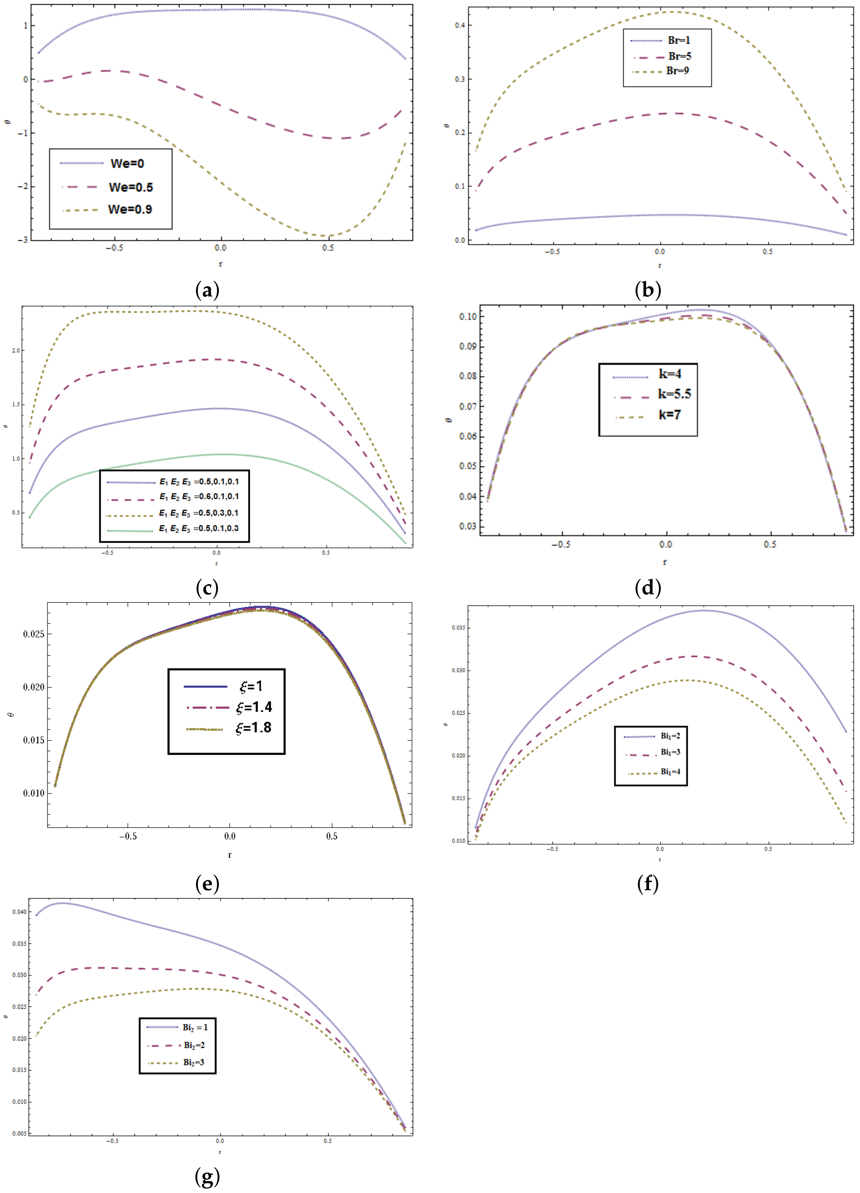
Figure 3a–g indicates the influence of different parameters on the fluid temperature distribution θ ( y ) . Figure 3a demonstrates that the magnitude of the temperature profile boosts while increasing the value of W e as Weissenberg number is the ratio of ealstic forces and viscous forces, therefore, an increase in W e dominates the viscosity and enhance the temperature of the fluid. It reveals that temperature is higher for Johnson–Segalman fluid than that of the viscous fluid temperature. Figure 3b reflects that when Brinkman number B r increases, the temperature goes up. This increase in the temperature is due to the viscous dissipation effects. Figure 3c portrays the effects of elastic parameters ( E 1 , E 2 , and E 3 ) on the temperature profile θ ( y ) . Increased temperature θ ( y ) can be seen with an increment in E 1 and E 2 and it decreases with increasing in E 3 . Figure 3d depicts that the temperature falls drastically towards the lower portion of the channel and continues to rise in the upper portion of the channel as the curvature parameter k rises. Figure 3e portrays the slip parameter activity indicating that temperature declines as the slip parameter rises near the upper channel wall, while it has an opposite impact close to the lower boundary. Figure 3f illustrates that enhancing the Biot number B i 1 reduces the temperature profile θ ( y ) near the upper inlet section but no impact has found in the lower inlet section. Similarly, Figure 3g reveals that the temperature profile θ ( y ) for Biot number B i 2 declines near the lower inlet section and has no noticeable impact near the upper inlet section.

5.3. Concentration Distribution

Figure 4a–h represents the effects of emerging parameters on the fluid concentration distribution ϕ ( y ) . Figure 4a depicts that concentration ϕ ( y ) increases when W e increases due to increase in elasticity of the fluid as W e physically represents the ratio of elastic to viscous forces. Figure 4b demonstrates that the concentration decreases when the Brinkman number intensifies. The effect of elastic parameters ( E 1 , E 2 , and E 3 ) are represented in Figure 4c. Here, with the increase in E 1 and E 2 , the concentration distribution decreases, while for E 3 concentration distribution ϕ ( y ) increases. Figure 4d shows the influence of slip parameter on ϕ ( y ) . This Figure shows that the concentration decays in the lower half portion of the channel, while the reverse trend is seen throughout the upper half portion of the channel. Figure 4e shows that the fluid concentration reduces towards the upper wall of the channel and rises in the lower portion of the channel as the curvature parameter k rises. Figure 4f indicates that the concentration declines with an increase in the Schmidt number ( S c ) which physically represents the ratio of momentum diffusivity and mass diffusivity. When we increase the value of Schmidt number, it actually dominates the mass diffusion and thus concentration of the fluid decays. The mass diffusion decays through increase in Schmidt number and, hence, concentration distribution ϕ ( y ) decreases. The effects of Biot numbers B i 3 and B i 4 are examined separately for the concentration profile ϕ ( y ) in the Figure 4g,h. It is found that variation of B i 3 has significant effect near the upper wall and it hardly shows any effect near the lower wall. Similarly, the effects of B i 4 are significant across the lower wall and the concentration profile ϕ ( y ) tends to decrease here. Biot number values are assumed to be greater than 1 and it indicates the non-uniform concentration fields inside the fluid. Also it reveals that convection is much quicker than conduction. From a realistic point of view, the parameters chosen are thus appropriate.

5.4. Coefficient of Heat-Transfer

In Figure 5a–e, we noticed the variability of the coefficient of heat transfer Z ( x ) for W e , B r , k, B i 1 , and B i 2 . Due to peristalsis, the nature of the heat transfer coefficient is oscillatory. The absolute value of the coefficient of overall heat transfer Z ( x ) falls as W e increases (see Figure 5a). Figure 5b illustrates that the coefficient of heat transfer results in an increase when Brinkman number intensifies. Figure 5c displays the curvature parameter’s behavior. This indicates that the coefficient of heat transfer Z ( x ) boosts with an increase in k. Further, Figure 5d,e analyze the effects of Biot numbers on heat transfer coefficient Z ( x ) . Increasing B i 1 the magnitude of heat transfer coefficient Z ( x ) increases and it decreases for B i 2 .

6. Conclusive Remarks

This article addresses the peristalsis of Johnson-Segalman fluid in a circular channel with walls’ compliance and convective heat and mass transfer conditions. Perturbation solution has been obtained under the long wave length and low Reynolds number approximation. The axial velocity of Johnson–Segalman is found to be greater than that of the Newtonian fluid. The velocity profile is skewed to the left because of curved channel, whereas the concentration and temperature profiles are inclined towards the right. Further, the velocity profile is not symmetric about the centre line in curved channel. At a certain level in the curved channel, the fluid approaches maximum velocity, which decreases in magnitude. The curved channel is transformed into the straight channel with relatively high value of curvature parameter. The results of this problem in Newtonian fluid model can be reduced when m = μ = 0 .

Author Contributions

Conceptualization, H.Y.; formal analysis, N.I.; investigation, A.H.; methodology, H.Y. and A.H.; software, A.H.; validation, H.Y. and N.I.; writing—original draft preparation, H.Y., N.I. and A.H.; writing—review and editing, N.I. and H.Y.; visualization, A.H. and N.I.; supervision, H.Y. All authors have read and agreed to the published version of the manuscript.

Funding

This research received no external funding.

Conflicts of Interest

The authors declare no conflict of interest.

Appendix A

The parameters appearing in the solutions are described here.
L 1 = k ( 8 E 1 π 3 ϵ cos ( 2 π ( x t ) ) 8 E 2 π 3 ϵ cos ( 2 π ( x t ) ) + 4 E 3 π 2 ϵ sin ( 2 π ( x t ) , L 2 = 2 η 1 ( 1 + ξ 2 ) 3 ( η 1 + μ ) , L 3 = 3 C 4 3 ( ( k η ) 2 ln ( k η ) + ( k + η ) 2 ln ( k + η ) ) , M = 1 k + η + B i 1 ln ( k + η ) , M 1 = 1 k η B i 2 ln ( k + η ) , M 2 = B i 1 k + η + B i 1 B i 2 ln ( k η ) , M 3 = B i 2 M + M 2 , M 4 = 8 C 2 C 4 ln ( k η ) ( k η ) , M 5 = 8 C 2 C 4 ln ( k + η ) ( k + η ) , M 6 = C 2 2 ( 2 + B i 2 ( k η ) ) ( k η ) 3 , M 7 = C 2 2 ( 2 + B i 1 ( k + η ) ) ( k + η ) 3 , M 8 = ( 2 + B i 2 ( k η ) ) ( k η ) , M 9 = ( 2 + B i 1 ( k + η ) ) ( k + η ) , M 10 = 4 B i 1 C 2 C 4 ln ( k + η ) 2 , M 11 = 4 B i 2 C 2 C 4 ln ( k η ) 2 , M 12 = C 2 2 ( k + η ) + C 4 2 ( k + η ) 2 , M 13 = 2 C 2 2 ( k + η ) 3 + 2 C 4 2 ( k + η ) , M 14 = B i 1 ( B r M 1 ( M 10 + M 5 M 7 C 4 2 M 9 ) + B M ( M 4 + M 6 + C 4 2 M 8 M 11 ) , N = B i 1 k η + B i 2 k + η + B i 1 B i 2 ( ln ( k η ) + ln ( k + η ) ) , N 1 = 18 ( C 13 C 2 + 2 C 4 ( C 11 + 8 C 2 C 4 2 ( 1 + ξ 2 ) ) ) ln ( k + η ) ( 2 + B i 1 ( k + η ) ) ln ( k + η ) k + η , N 2 = ( 18 ( C 11 C 2 ( k + η ) 4 ( 2 + B i 1 ( k + η ) ) ( η 1 + μ ) 4 C 2 4 ( 6 + B i 1 ( k + η ) ) ( η 1 μ ) ( 1 + ξ 2 ) + 36 C 4 C 2 3 ( 4 + B i 1 ( k + η ) ) ( η 1 μ ) ( 1 + ξ 2 ) + 216 C 2 2 C 4 2 ( k + η ) 4 ( 2 + B i 1 ( k + η ) ) μ ( 1 + ξ 2 ) + 9 C 4 ( k + η ) 8 ( 2 + B i 1 ( k + η ) ) ( η 1 + μ ) ( C 13 + 4 C 4 3 ( 1 + ξ 2 ) ) ) ,
N 3 = ( 18 ( C 11 C 2 ( k + η ) 4 ( 2 + B i 2 ( k η ) ) ( η 1 + μ ) 4 C 2 4 ( 6 + B i 2 ( k η ) ) ( η 1 μ ) ( 1 + ξ 2 ) + 36 C 4 C 2 3 ( 4 + B i 2 ( k η ) ) ( k η ) 2 ( η 1 μ ) ( 1 + ξ 2 ) + 216 C 2 2 C 4 2 ( k η ) 4 ( 2 + B i 2 ( k η ) ) ( k η ) 4 μ ( 1 + ξ 2 ) + 9 C 4 ( k η ) 8 ( 2 + B i 2 ( k η ) ) ( η 1 + μ ) ( C 13 + 4 C 4 3 ( 1 + ξ 2 ) ) ) , N 4 = 18 ( C 13 C 2 + 2 C 4 ( C 11 + 8 C 2 C 4 2 ( 1 + ξ 2 ) ) ) ln ( k η ) ( 2 + B i 2 ( k η ) ) ln ( k η ) k η , N 5 = 18 B i 1 C 2 ( C 11 ( η 1 + μ ) + 12 C 2 C 4 2 μ ( 1 + ξ 2 ) ) ( k + η ) 2 ( η 1 + μ ) + 36 B i 1 C 2 3 C 4 ( η 1 μ ) ( 1 + ξ 2 ) ( k + η ) 4 ( η 1 + μ ) , N 6 = 18 C 4 ( k + η ) ( C 13 + 4 C 4 3 ( 1 + ξ 2 ) + 9 B i 1 C 4 ( k + η ) 2 ( C 13 + 4 C 4 3 ( 1 + ξ 2 ) ) + 24 C 2 2 ( η 1 μ ) ( 1 + ξ 2 ) ( k + η ) 7 ( η 1 + μ ) , N 7 = 36 ( C 13 C 2 + 2 C 4 ( C 11 + 8 C 2 C 4 2 ( 1 + ξ 2 ) ) ) ln ( k + η ) k + η , N 8 = 36 C 2 ( C 11 ( η 1 + μ ) + 12 C 2 C 4 2 μ ( 1 + ξ 2 ) ) ( k + η ) 3 ( η 1 + μ ) , N 9 = 144 C 2 3 C 4 ( η 1 μ ) ( 1 + ξ 2 ) ) ( k + η ) 5 ( η 1 + μ ) , N 10 = 4 C 2 4 ( η 1 μ ) ( 1 + ξ 2 ) ) ( k + η ) 6 ( η 1 + μ ) , Y = B i 3 k η + B i 4 k + η + B i 3 B i 4 ( ln ( k η ) + ln ( k + η ) ) , Y 1 = C 2 2 ( k + η ) 3 C 4 2 ( k + η ) , Y 2 = 2 B i 3 ln ( k η ) k η , Y 3 = 1 k η 3 + 2 B i 4 k η ( k 2 η 2 ) 2 , Y 4 = B i 3 B i 4 ln ( k η ) 2 , Y 5 = B i 4 ln ( k + η ) ( 2 k + η + B i 3 ln ( k + η ) ) , Y 6 = 1 k + η 3 2 B i 4 k η ( k 2 η 2 ) 2 , Y 7 = 4 C 2 C 4 ( Y 4 + 2 B i 3 ln ( k η ) k + η + B i 4 ln ( k + η ) ( 2 k + η B i 3 ln ( k + η ) ) ) , Y 8 = Y 7 + 2 B i 4 ( C 2 2 ( k + η ) 3 + C 4 2 ( k + η ) ) + 2 B i 3 ( C 2 2 Y 6 + C 4 2 ( k η + 2 B i 4 k η ) ) , Y 9 = 4 B i 3 C 2 C 4 ln ( k + η ) 2 + Y 8 ( 1 k + η + B i 3 ln ( k + η ) ) Y , D = ( 18 ( C 11 C 2 ( k + η ) 4 ( 2 + B i 3 ( k + η ) ) ( η 1 + μ ) 4 C 2 4 ( 6 + B i 3 ( k + η ) ) ( η 1 μ ) ( 1 + ξ 2 ) + 36 C 4 C 2 3 ( k + η ) 2 ( 4 + B i 3 ( k + η ) ) ( η 1 μ ) ( 1 + ξ 2 ) + 216 C 2 2 C 4 2 ( k + η ) 4 ( 2 + B i 3 ( k + η ) ) μ ( 1 + ξ 2 ) + 9 C 4 ( k + η ) 8 ( 2 + B i 3 ( k + η ) ) ( η 1 + μ ) ( C 13 + 4 C 4 3 ( 1 + ξ 2 ) ) ) , D 1 = ( 18 ( C 11 C 2 ( k η ) 4 ( 2 + B i 4 ( k η ) ) ( η 1 + μ ) 4 C 2 4 ( 6 + B i 4 ( k η ) ) ( η 1 μ ) ( 1 + ξ 2 ) + 36 C 4 C 2 3 ( k η ) 2 ( 4 + B i 4 ( k η ) ) ( η 1 μ ) ( 1 + ξ 2 ) + 216 C 2 2 C 4 2 ( k η ) 4 ( 2 + B i 4 ( k η ) ) μ ( 1 + ξ 2 ) + 9 C 4 ( k η ) 8 ( 2 + B i 4 ( k η ) ) ( η 1 + μ ) ( C 13 + 4 C 4 3 ( 1 + ξ 2 ) ) ) , D 2 = 18 ( C 13 C 2 + 2 C 4 ( C 11 + 8 C 2 C 4 2 ( 1 + ξ 2 ) ) ) ln ( k η ) ( 2 + B i 4 ( k η ) ) ln ( k η ) k η , D 3 = 18 ( C 13 C 2 + 2 C 4 ( C 11 + 8 C 2 C 4 2 ( 1 + ξ 2 ) ) ) ln ( k + η ) ( 2 + B i 3 ( k + η ) ) ln ( k + η ) k + η , D 4 = 18 B i 3 ( C 13 C 2 + 2 C 4 ( C 11 + 8 C 2 C 4 2 ( 1 + ξ 2 ) ) ) ln ( k + η ) 2 ,
D 5 = 18 C 4 ( k + η ) ( C 13 + 4 C 4 3 ( 1 + ξ 2 ) + 9 B i 3 C 4 ( k + η ) 2 ( C 13 + 4 C 4 3 ( 1 + ξ 2 ) ) + 24 C 2 2 ( η 1 μ ) ( 1 + ξ 2 ) ( k + η ) 5 ( η 1 + μ ) , D 6 = 4 B i 3 C 2 4 ( η 1 μ ) ( 1 + ξ 2 ) ( k + η ) 6 ( η 1 + μ ) , D 7 = 18 B i 3 C 2 ( C 11 ( η 1 + μ ) + 12 C 2 C 4 2 μ ( 1 + ξ 2 ) ) ( k + η ) 2 ( η 1 + μ ) , D 8 = 1 Y ( B i 3 ( D 2 D 1 ( k η ) 7 ( η 1 + μ ) ) + B i 4 ( D ( k + η ) 7 ( η 1 + μ ) D 3 ) ) ( 1 k + η + B i 3 ln ( k + η ) ) .

References

  1. Latham, T.W. Fluid Motion in a Peristaltic Pump; MIT: Cambridge, MA, USA, 1966. [Google Scholar]
  2. Shapiro, A.H.; Jaffrin, M.Y.; Wienberg, S.L. Peristaltic pumping with long wavelengths at low Reynolds number. J. Fluid Mech. 1969, 37, 799–825. [Google Scholar] [CrossRef]
  3. Yin, F.; Fung, Y.C. Peristaltic wave in circular cylindrical tubes. J. Appl. Mech. 1969, 36, 579–587. [Google Scholar] [CrossRef]
  4. Hayat, T.; Iqbal, R.; Tanveer, A.; Alsaedi, A. Mixed convective peristaltic transport of Carreau-Yasuda nanofluid in a tapered asymmetric channel. J. Mol. Liq. 2016, 223, 1100–1113. [Google Scholar] [CrossRef]
  5. Ramesh, K. Effects of slip and convective conditions on the peristaltic flow of couple stress fluid in an asymmetric channel through porous medium. Comput. Meth. Prog. Biomed. 2016, 135, 1–14. [Google Scholar] [CrossRef] [PubMed]
  6. Tripathi, D.; Bég, O.A. Peristaltic propulsion of generalized Burgers’ fluids through a non-uniform porous medium: A study of chyme dynamics through the diseased intestine. Math. Biosci. 2014, 248, 67–77. [Google Scholar] [CrossRef]
  7. Shehzad, S.A.; Abbasi, F.M.; Hayat, T.; Alsaadi, F. Model and comparative study for peristaltic transport of water based nanofluids. J. Mol. Liq. 2015, 209, 723–728. [Google Scholar] [CrossRef]
  8. Abbasi, F.M.; Hayat, T.; Ahmad, B. Peristaltic transport of copper–water nanofluid saturating porous medium. Phys. Low Dimens. Nanostruct. 2015, 67, 47–53. [Google Scholar] [CrossRef]
  9. Gad, N.S. Effects of Hall currents on peristaltic transport with compliant walls. Appl. Math. Comput. 2014, 235, 546–554. [Google Scholar] [CrossRef]
  10. Abbas, M.A.; Bai, Y.Q.; Bhatti, M.M.; Rashidi, M.M. Three dimensional peristaltic flow of hyperbolic tangent fluid in non-uniform channel having flexible walls. Alex. Eng. J. 2016, 55, 653–662. [Google Scholar] [CrossRef] [Green Version]
  11. Lachiheb, M. Effect of coupled radial and axial variability of viscosity on the peristaltic transport of Newtonian fluid. Appl. Math. Comput. 2014, 244, 761–771. [Google Scholar] [CrossRef]
  12. Shit, G.C.; Roy, M. Hydromagnetic effect on inclined peristaltic flow of a couple stress fluid. Alex. Eng. J. 2014, 4, 949–958. [Google Scholar] [CrossRef] [Green Version]
  13. Ramesh, K.; Tripathi, D.; Bhatti, M.M.; Khalique, C.M. Electro-osmotic flow of hydromagnetic dusty viscoelastic fluids in a microchannel propagated by peristalsis. J. Mol. Liq. 2020, 314, 113568. [Google Scholar] [CrossRef]
  14. Tariq, H.; Khan, A.A.; Zaman, A. Theoretical analysis of peristaltic viscous fluid with inhomogeneous dust particles. Arab. J. Sci. Eng. 2020. [Google Scholar] [CrossRef]
  15. Hina, S.; Mustafa, M.; Hayat, T.; Alotaibi, N.D. On peristaltic motion of pseudoplastic fluid in a curved channel with heat/mass transfer and wall properties. Appl. Math. Comput. 2015, 263, 378–391. [Google Scholar] [CrossRef]
  16. Bhatti, M.M.; Elelamy, A.F.; Sait, S.M.; Ellahi, R. Hydrodynamics interactions of metachronal waves on particulate-liquid motion through a ciliated annulus: Application of bio-engineering in blood clotting and endoscopy. Symmetry 2020, 14, 532. [Google Scholar] [CrossRef] [Green Version]
  17. Fomicheva, M.; Müller, W.H.; Vilchevskaya, E.N.; Bessonov, N. Funnel flow of a Navier-Stokes-fluid with potential applications to micropolar media. Facta Univ. Ser. Mech. Eng. 2019, 17, 255–267. [Google Scholar] [CrossRef]
  18. Javed, M. A mathematical framework for peristaltic mechanism of non-Newtonian fluid in an elastic heated channel with Hall effect. Multidiscip. Model. Mater. Struct. 2020. [Google Scholar] [CrossRef]
  19. Bhandari, D.S.; Tripathi, D.; Narla, V.K. Pumping flow model for couple stress fluids with a propagative membrane contraction. Int. J. Mech. Sci. 2020. [Google Scholar] [CrossRef]
  20. Hayat, T.; Wang, Y.; Siddiqi, A.M.; Hutter, K. Peristaltic flow of a Johnson-Segalman fluid in a planar channel. Math. Probl. Eng. 2003, 2003, 1–23. [Google Scholar] [CrossRef]
  21. Hayat, T.; Mumtaz, S. Resonant oscillations of plate in an electrically conducting rotating Johnson-Segalman fluid. Comp. Math. Appl. 2005, 50, 1669–1676. [Google Scholar] [CrossRef]
  22. Hayat, T.; Afsar, A.; Ali, N. Peristaltic transport of a Johnson–Segalman fluid in an asymmetric channel. Math. Comput. Model. 2005, 47, 380–400. [Google Scholar] [CrossRef]
  23. Elshahed, M.; Haroun, M.H. Peristaltic transport of Johnson–Segalman fluid under effect of a magnetic field. Math. Probl. Eng. 2005, 2005, 663–677. [Google Scholar] [CrossRef]
  24. Wang, Y.; Hayat, T.; Hutter, K. Peristaltic transport of a Johnson–Segalman fluid through a deformable tube. Theor. Comput. Fluid Dyn. 2007, 21, 369–380. [Google Scholar] [CrossRef]
  25. Sato, H.; Kawai, T.; Fujita, T.; Okabe, M. Two dimensional peristaltic flow in curved channels. Trans. Jpn. Soc. Mech. Eng. B 2000, 66, 679–685. [Google Scholar] [CrossRef] [Green Version]
  26. Ali, N.; Sajid, M.; Hayat, T. Long wavelength flow analysis in a curved channel. Z. Naturforsch. 2010, 65, 191–196. [Google Scholar] [CrossRef] [Green Version]
  27. Majeed, A.; Javed, T.; Ghaffari, A.; Rashidi, M.M. Analysis of heat transfer due to stretching cylinder with partial slip and prescribed heat flux: A Chebyshev Spectral Newton Iterative Scheme. Alex. Eng. J. 2015, 54, 1029–1036. [Google Scholar] [CrossRef] [Green Version]
  28. Hina, S.; Mustafa, M.; Hayat, T.; Alsaedi, A. Peristaltic flow of Powell-Eyring fluid in curved channel with heat transfer: A useful application in biomedicine. Comp. Meth. Prog. Biomed. 2016, 135, 89–100. [Google Scholar] [CrossRef]
  29. Abbasi, F.M.; Hayat, T.; Alsaedi, A. Numerical analysis for MHD peristaltic transport of Carreau-Yasuda fluid in a curved channel with Hall effects. J. Magn. Magn. Mat. 2015, 382, 104–110. [Google Scholar] [CrossRef]
  30. Ali, N.; Javid, K.; Sajid, M.; Zaman, A.; Hayat, T. Numerical simulations of Oldroyd 8-constant fluid flow and heat transfer in a curved channel. Int. J. Heat Mass Transf. 2016, 94, 500–508. [Google Scholar] [CrossRef]
  31. Ahmed, R.; Ali, N.; Khan, S.U.; Tlili, I. Numerical simulations for mixed convective hydromagnetic peristaltic flow in a curved channel with joule heating features. AIP Adv. 2020, 10, 075303. [Google Scholar] [CrossRef]
  32. Hina, S.; Hayat, T.; Alsaedi, A. Heat and mass transfer effects on the peristaltic flow of Johnson–Segalman fluid in a curved channel with compliant walls. Int. J. Heat Mass Transf. 2012, 55, 3511–3521. [Google Scholar] [CrossRef]
  33. Mehmood, O.U.; Qureshi, A.A.; Yasmin, H.; Uddin, S. Thermo-mechanical analysis of non Newtonian peristaltic mechanism: Modified heat flux model. Phys. A Stat. Mech. Appl. 2020, 550, 124014. [Google Scholar] [CrossRef]
  34. Hayat, T.; Javid, M.; Hendi, A.A. Peristaltic transport of viscous fluid in a curved channel with compliant walls. Int. J. Heat Mass Transf. 2011, 54, 1615–1621. [Google Scholar] [CrossRef]
  35. Riaz, A.; Ellahi, R.; Sait, S.M. Role of hybrid nanoparticles in thermal performance of peristaltic flow of Eyring—Powell fluid model. J. Them. Anal. Calorim. 2020. [Google Scholar] [CrossRef]
  36. Hayat, T.; Yasmin, H.; Al-Yami, M. Soret and Dufour effects in peristaltic transport of physiological fluid with chemical reaction: A mathematical analysis. Comput. Fluids 2014, 89, 242–253. [Google Scholar] [CrossRef]
  37. Yasmin, H.; Farooq, S.; Awais, M.; Alsaedi, A.; Hayat, T. Significance of heat and mass process in peristalsis of a rheological material. Heat Trans. Res. 2019, 50, 1561–1580. [Google Scholar] [CrossRef]
  38. Hayat, T.; Yasmin, H.; Ahmad, B.; Chen, B. Simultaneous effects of convective conditions and nanoparticles on peristaltic motion. J. Mol. Liq. 2014, 193, 74–82. [Google Scholar] [CrossRef]
  39. Hayat, T.; Bibi, A.; Yasmin, H.; Alsaadi, F.E. Magnetic field and thermal radiation effects in peristaltic flow with heat and mass convection. J. Ther. Sci. Eng. Appl. 2018, 10, 051018. [Google Scholar] [CrossRef]
  40. Yasmin, H.; Hayat, T.; Alsaedi, A.; Alsulami, H.H. Peristaltic transport of Johnson-Segalman fluid in an asymmetric channel with convective boundary conditions. Appl. Math. Mech.-Engl. Ed. 2014, 35, 697–716. [Google Scholar] [CrossRef]
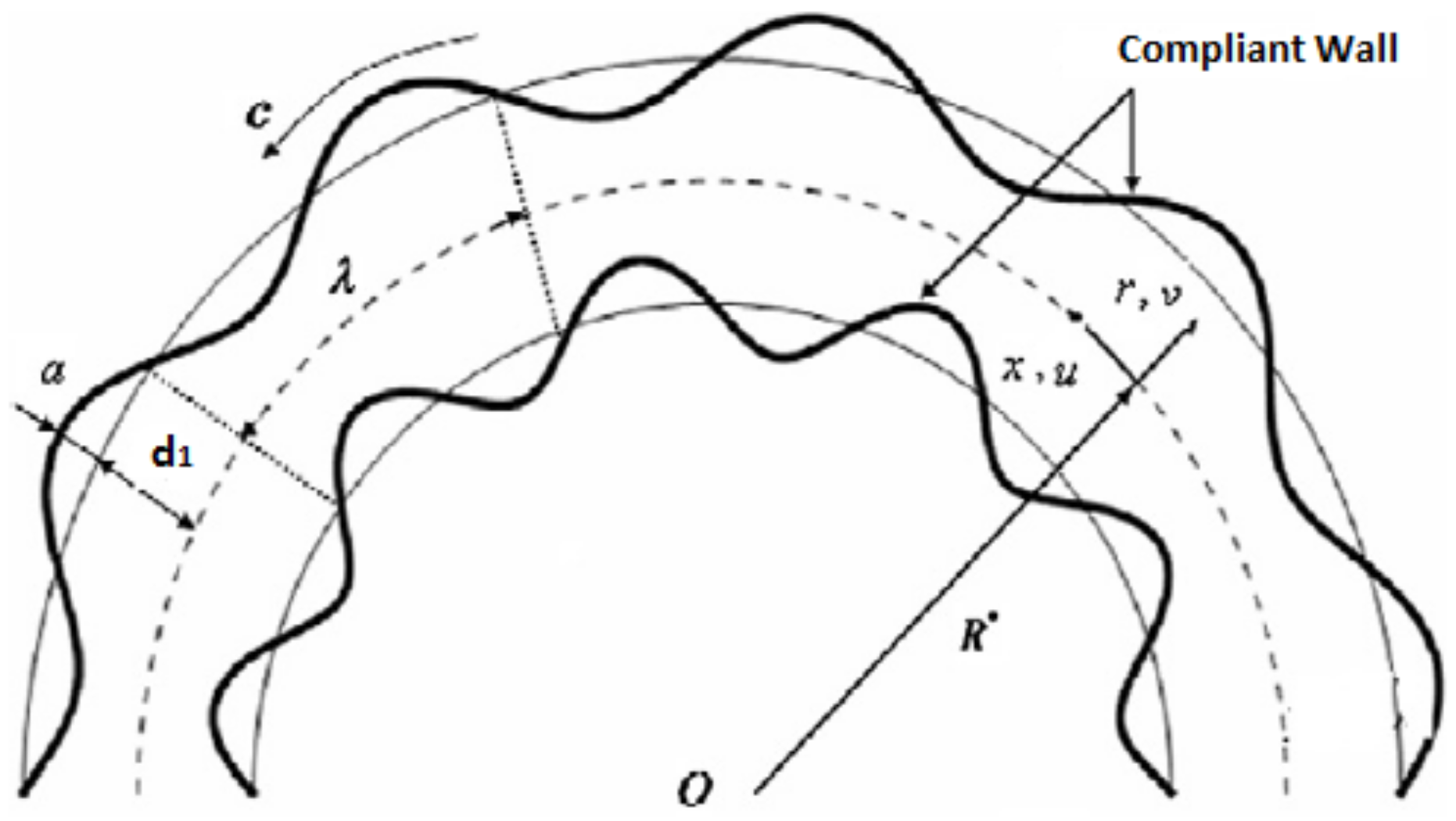
Figure 1. Schematic diagram of the problem.
Symmetry 12 01475 g001
Figure 2. (a) Variation of W e on u when E 1 = 0.02 ;   E 2 = 0.01 ;   E 3 = 0.1 ;   ϵ = 0.2 ;   k = 1.5 ;   ξ = 0.5 ;   μ = 0.1 ;   η 1 = 0.1 ;   t = 0.1 ;   x = 0.2 . ; (b) Variation of k on u when E 1 = 0.02 ;   E 2 = 0.01 ;   E 3 = 0.1 ;   ϵ = 0.2 ;   W e = 0.01 ;   ξ = 0.5 ;   μ = 0.1 ;   η 1 = 0.1 ;   t = 0.1 ;   x = 0.2 . ; (c) Variation of E 1 , E 2 , E 3 on u when ϵ = 0.2 ;   W e = 0.2 ;   k = 1.5 ;   ξ = 0.5 ;   μ = 0.1 ;   η 1 = 0.1 ;   t = 0.1 ;   x = 0.2 .
Symmetry 12 01475 g002
Figure 3. (a) effect of W e on θ when E 1 = 0.5 ; E 2 = 0.04 ; E 3 = 0.01 ; ϵ = 0.15 ; k = 10 ; B r = 1.8 ; ξ = 1.8 ; μ = 0.5 ; η 1 = 0.6 ; t = 0.1 ; x = 0.2 ; B i 1 = 10 ; B i 2 = 8 . (b) variation of B r on θ when E 1 = 0.04 ; E 2 = 0.03 ; E 3 = 0.01 ; ϵ = 0.15 ; k = 1.5 ; W e = 0.01 ; ξ = 1.9 ; μ = 0.6 ; η 1 = 0.8 ; t = 0.1 ; x = 0.2 ; B i 1 = 10 ; B i 2 = 8 . (c) variation of E 1 , E 2 , E 3 on θ when ϵ = 0.15 ; W e = 0.01 ; k = 1.5 ; B r = 0.5 ; ξ = 1.9 ; ; μ = 0.5 ; η 1 = 0.8 ; t = 0.1 ; x = 0.2 ; B i 1 = 10 ; B i 2 = 8 . (d) variation of k on θ when E 1 = 0.05 ; E 2 = 0.04 ; E 3 = 0.01 ; ϵ = 0.15 ; W e = 0.01 ; B r = 1.8 ; ξ = 2.9 ; μ = 0.5 ; η 1 = 0.8 ; t = 0.1 ; x = 0.2 ; B i 1 = 10 ; B i 2 = 8 . (e) variation of ξ on θ when E 1 = 0.05 ; E 2 = 0.03 ; E 3 = 0.01 ; ϵ = 0.15 ; W e = 0.01 ; B r = 1.5 ; k = 2.9 ; μ = 0.6 ; η 1 = 0.8 ; t = 0.1 ; x = 0.2 ; B i 1 = 10 ; B i 2 = 8 . (f) Variation of B i 1 on θ when E 1 = 0.04 ; E 2 = 0.03 ; E 3 = 0.01 ; ϵ = 0.15 ; W e = 0.01 ; B r = 2.5 ; ξ = 1.9 ; μ = 0.6 ; η 1 = 0.8 ; k = 1.5 t = 0.1 ; x = 0.2 ; B i 2 = 8 . (g) variation of B i 2 on θ when E 1 = 0.04 ; E 2 = 0.03 ; E 3 = 0.01 ; ϵ = 0.15 ; W e = 0.01 ; B r = 2.5 ; ξ = 1.9 ; μ = 0.6 ; η 1 = 0.8 ; k = 1.5 t = 0.1 ; x = 0.2 ; B i 1 = 10 .
Symmetry 12 01475 g003
Figure 4. (a) Variation of W e on ϕ when E 1 = 0.5 ; E 2 = 0.04 ; E 3 = 0.01 ; ϵ = 0.15 ; k = 10 ; B r = 0.5 ; ξ = 1.8 ; μ = 0.5 ; η 1 = 0.6 ; t = 0.1 ; x = 0.2 ; S c = 1 ; S r = 1 ; B i 1 = 10 ; B i 2 = 8 . (b) Variation of B r on ϕ when E 1 = 0.04 ; E 2 = 0.03 ; E 3 = 0.01 ; ϵ = 0.15 ; k = 1.5 ; W e = 0.01 ; ξ = 1.9 ; S c = 1 ; S r = 1 ; μ = 0.6 ; η 1 = 0.8 ; t = 0.1 ; x = 0.2 ; B i 1 = 10 ; B i 2 = 8 . (c) Variation of E 1 , E 2 , E 3 on ϕ when ϵ = 0.15 ; W e = 0.01 ; k = 1.5 ; B r = 0.5 ; ξ = 1.9 ; μ = 0.5 ; η 1 = 0.8 ; t = 0.1 ; x = 0.2 ; S c = 1 ; S r = 1 ; B i 1 = 10 ; B i 2 = 8 . (d) Variation of ξ on ϕ when E 1 = 0.05 ; E 2 = 0.03 ; E 3 = 0.01 ; ϵ = 0.15 ; W e = 0.01 ; B r = 0.5 ; k = 2.5 ; μ = 0.6 ; η 1 = 0.8 ; t = 0.1 ; x = 0.2 ; B i 1 = 10 ; B i 2 = 8 ; S c = 1 ; S r = 1 . (e) variation of k on ϕ when E 1 = 0.05 ; E 2 = 0.04 ; E 3 = 0.01 ; ϵ = 0.15 ; W e = 0.01 ; B r = 1.5 ; ξ = 2.9 ; μ = 0.5 ; η 1 = 0.8 ; t = 0.1 ; x = 0.2 ; B i 1 = 10 ; B i 2 = 8 ; S c = 1 ; S r = 1 . (f) Variation of S c on ϕ when E 1 = 0.04 ; E 2 = 0.03 ; E 3 = 0.01 ; ϵ = 0.15 ; W e = 0.01 ; B r = 1 ; ξ = 1.9 ; k = 1.5 ; S r = 1 ; μ = 0.6 ; η 1 = 0.8 ; t = 0.1 ; x = 0.2 ; B i 1 = 10 ; B i 2 = 8 . (g) Variation of B i 1 on ϕ when E 1 = 0.04 ; E 2 = 0.03 ; E 3 = 0.01 ; ϵ = 0.15 ; W e = 0.01 ; B r = 0.5 ; ξ = 1.9 ; μ = 0.6 ; η 1 = 0.8 ; k = 1.5 ; t = 0.1 ; x = 0.2 ; B i 2 = 8 ; S c = 1 ; S r = 1 . (h) Variation of B i 2 on ϕ when E 1 = 0.04 ; E 2 = 0.03 ; E 3 = 0.01 ; ϵ = 0.15 ; W e = 0.01 ; B r = 0.5 ; ξ = 1.9 ; μ = 0.6 ; η 1 = 0.8 ; k = 1.5 ; t = 0.1 ; x = 0.2 ; B i 1 = 10 ; S c = 1 ; S r = 1 .
Symmetry 12 01475 g004aSymmetry 12 01475 g004b
Figure 5. (a) Variation of W e on Z when E 1 = 0.5 ; E 2 = 0.04 ; E 3 = 0.01 ; ϵ = 0.15 ; k = 10 ; B r = 0.5 ; ξ = 1.8 ; μ = 0.5 ; η 1 = 0.6 ; t = 0.1 ; B i 1 = 10 ; B i 2 = 8 . (b) Variation of B r on Z when E 1 = 0.5 ; E 2 = 0.04 ; E 3 = 0.01 ; ϵ = 0.15 ; k = 10 ; W e = 0.005 ; ξ = 1.8 ; μ = 0.5 ; η 1 = 0.6 ; t = 0.1 ; B i 1 = 10 ; B i 2 = 8 . (c) Variation of k on Z when E 1 = 0.5 ; E 2 = 0.04 ; E 3 = 0.01 ; W e = 0.005 ; ϵ = 0.15 ; k = 10 ; B r = 0.5 ; ξ = 1.8 ; μ = 0.5 ; η 1 = 0.6 ; t = 0.1 ; B i 1 = 10 ; B i 2 = 8 . (d) Variation of B i 1 on Z when E 1 = 0.5 ; E 2 = 0.04 ; E 3 = 0.01 ; ϵ = 0.15 ; W e = 0.005 ; B r = 0.5 ; ξ = 1.8 ; μ = 0.5 ; η 1 = 0.6 ; k = 10 ; t = 0.1 ; x = 0.2 ; B i 2 = 8 . (e) Variation of B i 2 on Z when E 1 = 0.5 ; E 2 = 0.04 ; E 3 = 0.01 ; ϵ = 0.15 ; W e = 0.005 ; B r = 0.5 ; ξ = 1.8 ; μ = 0.5 ; η 1 = 0.6 ; k = 10 ; t = 0.1 ; x = 0.2 ; B i 1 = 10 .
Symmetry 12 01475 g005