Article

Flow Symmetry and Heat Transfer Characteristics of Winglet Vortex Generators Arranged in Common Flow up Configuration

School of Mechanical Engineering, Key Laboratory of Railway Vehicle Thermal Engineering of Ministry of Education of China, Lanzhou Jiaotong University, Lanzhou 730070, China
*
Author to whom correspondence should be addressed.
Symmetry 2020, 12(2), 247; https://doi.org/10.3390/sym12020247
Submission received: 31 December 2019 / Revised: 2 February 2020 / Accepted: 4 February 2020 / Published: 5 February 2020
(This article belongs to the Special Issue Symmetry in Fluid Flow)

Abstract

:
The generation of longitudinal vortices is an effective method for promoting thermal performance with a relative low-pressure penalty in heat exchangers. The winglet pair can generate symmetrical longitudinal vortices on the cross-section of the channel. The heat transfer and pressure-loss characteristics of a pair of winglet vortex generators with different transverse pitches are numerically studied in this paper. The winglet pair arranged in a common flow up configuration generates a pair of symmetrical longitudinal main vortices with counter-rotating directions. The symmetrical flow structure induces fluid to flow from the bottom towards the top of the channel in the common flow region between the longitudinal vortices. The flow symmetry of the longitudinal vortices and the heat transfer performance are strongly affected by the transverse pitch of the winglet pair owing to the interaction between the longitudinal vortices. The optimal transverse pitch of the studied winglet pair with the best thermal performance is reported. The increments in the vortex intensity and the Nusselt number for the optimal pitch are increased by up to 21.4% and 29.2%, respectively.

1. Introduction

Heat exchangers are extensively applied in the chemical, engine, petroleum, power, and food industries. The thermal resistance in a heat exchanger is mainly dominated by the gas side [1]. The generation of longitudinal vortices by vortex generators (VG) is an effective method for enhancing the gas-side performance with relatively low-pressure loss and has received extensive attention in the field of heat exchange [2,3,4,5,6,7,8,9,10,11]. Several parameters, including VG geometry, attack angle, and channel spacing, can influence the thermal performance. Wu and Tao [12] reported that the best heat transfer performance of the studied channel with VG was obtained when the attack angle was equal to 45 degrees. Min et al. [13] developed an improved rectangular VG by cutting all of the corners of the normal VG. Their experimental results showed that the new VG has higher heat transfer performance than the reference VG. Tian et al. [14] compared the thermal performance between the winglet pairs arranged in both CFU and CFD configurations and fond that the increment of Nu of CFU is higher than that of CFD. Wu and Tao [15] also numerically studied a two-row tube-fin heat exchanger with the VGs arranged in pairs in a common flow up (CFU) or common flow down (CFD) configuration. The results showed that better heat transfer performance and lower pressure loss can be obtained by the optimization of the VG location, size and attack angle. Li et at. [16] experimentally studied a fin with radiantly arranged VGs and showed that the fin with the radiantly-arranged VGs had a better comprehensive performance than the studied wavy fin. Naik and Tiwari [17] studied the location of VGs in the CFD configuration and reported that heat transfer is the highest for the VGs located in the adjacent region.
Song et al. [18] studied curved VGs with different baseline lengths and locations. The experimental results showed that a curved VG with a large size is beneficial for heat transfer when the Reynolds number is large, and a small VG is conducive to heat transfer improvement for a small Reynolds number. The results for the thermal–hydraulic performance of curved concave and convex VGs with different center angles and attack angles are presented in [19]. The curved concave VG has better thermal performance than the normal plane VG, and an optimal center angle exists with the highest thermal performance. Meanwhile, the curved convex VG has lower thermal performance compared with the plane VG. Lu and Zhai [20] also reported the heat transfer performance of curved VGs. Better performance was attained with three VGs located at certain horizontal and vertical distances. Han et al. [21] numerically compared the performance of the planar and curved arc VGs and found that a curved VG can introduce more fluid into the zone behind the tube and has better performance. Lu and Zhai [22] studied the performance of tear-drop VGs arranged in a CFU configuration. They found that tear-drop VGs can enhance the heat transfer with a negligible increase in the pressure drop. Sarangi and Mishra [23] studied the location of the VGs in the common flow up configuration and found that the placement of the VGs near the central tube was effective for heat transfer enhancement.
Studies of the interaction characteristics between the vortices have rarely been reported in the literature. Song et al. [24,25,26] proposed a dimensionless parameter Se to quantify the secondary flow intensity. The characteristics of the interactions between the two counter-rotating vortices were quantitatively analyzed using Se in [25]. Quantitative studies of vortex intensity indicate that the value of Se in the heat-exchanger channel determines the heat transfer intensity [26], and the optimal VG configuration with the highest thermal performance can be attained by considering the vortex interaction [27,28,29].
The above review shows that despite an enormous amount of research about the application of VGs, the vortex interaction and reasonable transverse pitch of a pair of winglet VGs arranged in CFU configuration have not been reported. The flow field in the channel with a pair of winglet VGs has perfect symmetry. The flow symmetry of the longitudinal vortices and the heat transfer performance are clearly affected by the transverse pitch of the winglets owing to the interaction between the longitudinal vortices. In this work, the symmetrical flow structure and the vortex intensity of a pair of winglet VGs arranged in common flow up configuration was studied with different transverse pitches. An optimal transverse pitch with the highest performance is presented by considering the interaction of the longitudinal vortices. The results can contribute to the design and optimization process of the heat exchangers.

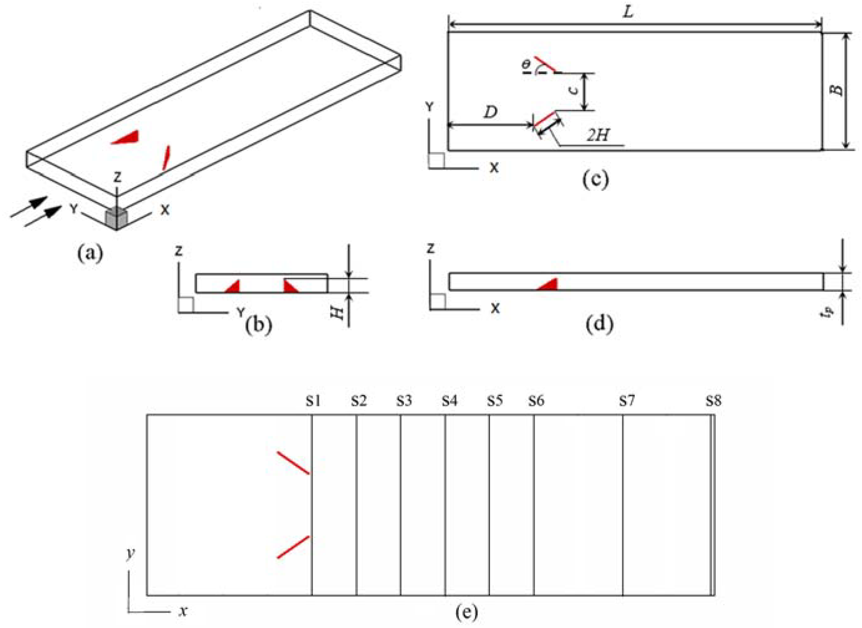
2. Physical Model, Methods and Formulations

The studied model is schematically presented in Figure 1. Two parallel fins form a flow channel with a pair of delta winglet VGs arranged on the lower fin. The attack angle of the winglet VGs is fixed at θ = 35°. The winglet height is H = 1.4 mm, and the baseline equals 2H. The net height of the channel is tp = 2 mm. The channel width and length are B = 10H and L = 31.5H, respectively. The winglet vortex generators are arranged in CFU configuration with a transverse pitch of c and a distance of D = 10 mm from the inlet. The studied transverse pitches are named c1-c7 with c/(2Hsinθ) ratios equal to 3.0, 2.5, 2.0, 1.5, 1.0, 0.5 and 0.0, respectively.
The compact forms of the governing equations for viscous incompressible air in steady and laminar developing flow without considering the volume force and viscous dissipation are summarized as follows:
x i ( ρ u i ) = 0
x i ( ρ u i u k ) = x i ( μ u k x i ) p x k
x i ( ρ c p u i T ) = x i ( λ T x i )
The boundary conditions of the studied model in Figure 1 are given by the follow equations.
At the inlet:
u in ( x ,   y ,   z ) = u 0 , v in ( x ,   y ,   z ) = 0 , w in ( x ,   y ,   z ) = 0 , T in ( x ,   y ,   z ) = T 0
At the outlet:
x u out ( x , y , z ) = 0 , x v out ( x , y , z ) = 0 , x w out ( x , y , z ) = 0 , x T out ( x , y , z ) = 0
At the solid surfaces:
u ( x , y , z ) = 0 , v ( x , y , z ) = 0 , w ( x , y , z ) = 0 , T = T w
The fin spacing is selected as the hydraulic diameter, dh = tp. The parameters are as follows:
R e = ρ . u m . d h μ
f = Δ p d h ( L ρ u m 2 / 2 )
N u = d h T w T s ( x ) T n
Here, Ts(x) is area-averaged temperature on cross-section:
T s ( x ) = A u ( x , y , z ) T ( x , y , z ) d A A u ( x , y , z ) d A
The secondary flow intensity is given by [24,25,26]:
S e = ρ d h U s μ
The secondary flow characteristic velocity is given by:
U s = d h | ω n |
where ωn is the vortex flux along the main flow direction.
The above governing equations were discretized by the finite control volume method with the second-order central difference scheme and solved by the code written by FORTRAN. The velocity and pressure are coupled using the SIMPLE algorithm [1]. The interaction of the governing equations first runs for a thousand steps and then convergence is judged with a residual of 10−6 for the equations when the relative errors of Nu, f and T between every 200 iterations are less than 0.01%.
The grid independence was tested between three grids 140 × 118 × 26, 194 × 142 × 32 and 234 × 168 × 37 at Re = 1000 and c3 = 2, as shown in Table 1. The differences in Nu and f between the neighboring grids were smaller than 1%. The numerical results were not dependent on the grid number. The 194 × 142 × 32 medium-size grid was adopted to obtain the numerical results in the present paper. The mesh of the model is shown in Figure 2.
The numerical method and code were validated by comparison with the results of Tian et al. [14]. The model for comparison is the same as that used in [14] and is also a channel formed by two parallel plates with a pair of winglet VGs in CFU configuration. The comparisons of Nu and f in the range of Re between 200 and 1200 are presented in Figure 3. The numerical results for both Nu and f are in good agreement with the results reported in [14]. The largest difference in Nu was approximately 2.1% when Re = 200 and was less than 1.1% when Re > 200. The largest difference in f was less than 3.8% in the studied range of Re. Thus, the numerical method and code are reliable.

3. Results and Discussions

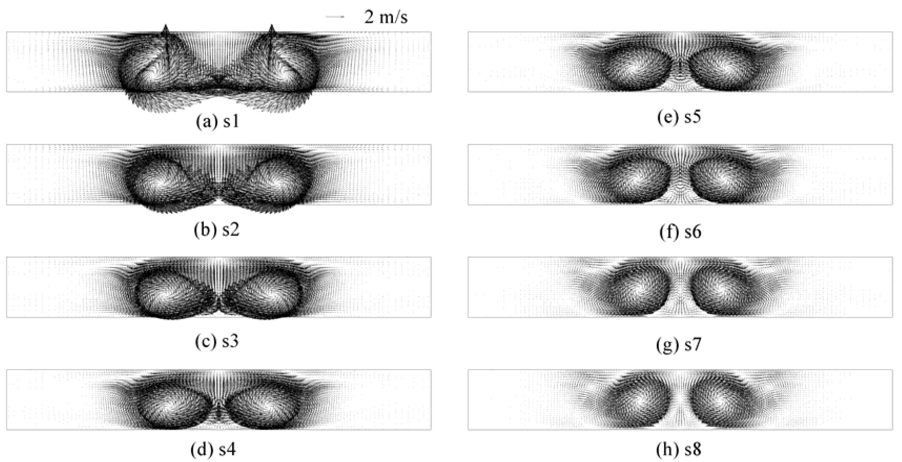
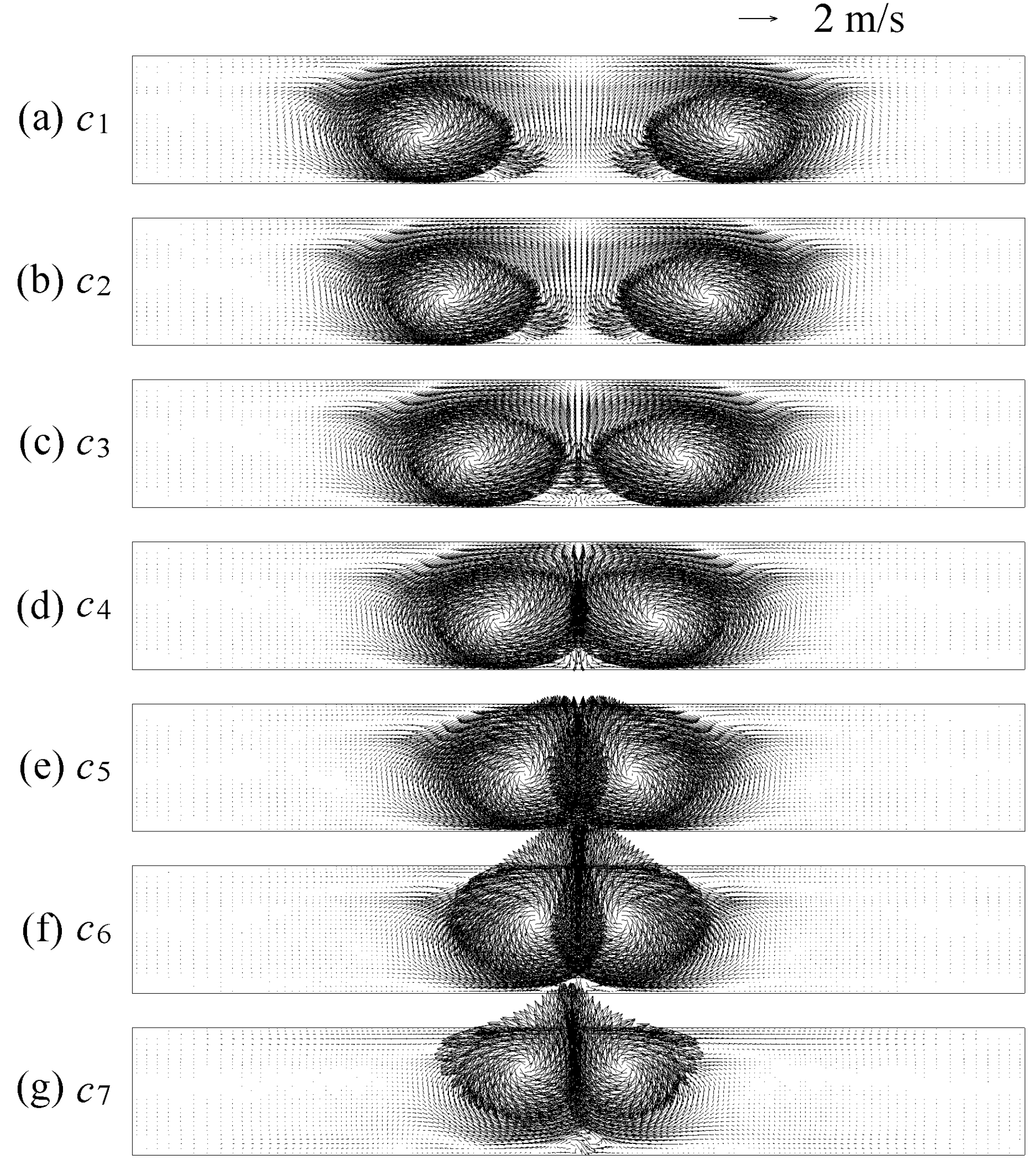
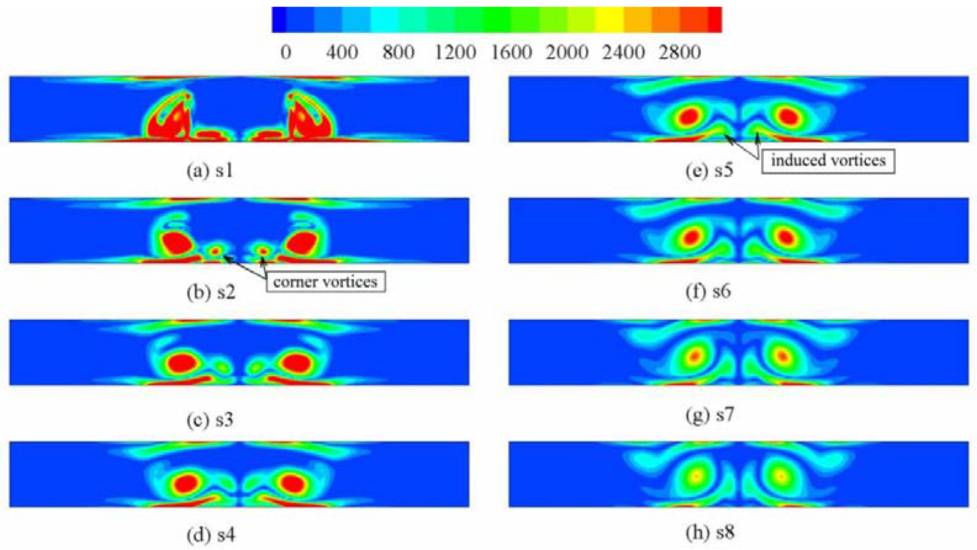
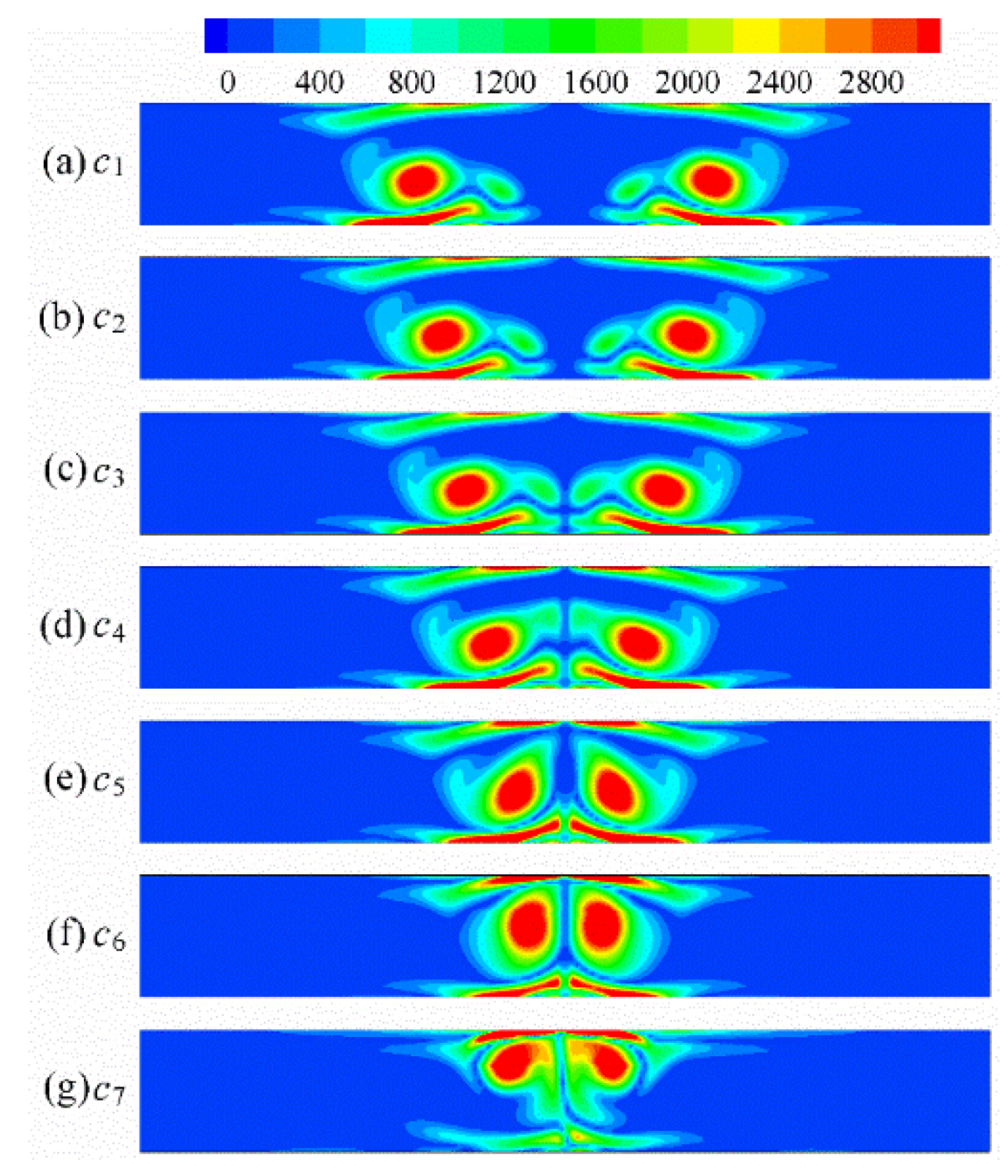
3.1. Symmetrical Vortex Structure and Vortex Intensity

The longitudinal vortices on the selected cross-sections are shown in Figure 4 for c3 when Re = 1800. The longitudinal vortices are symmetrical about the center of the cross-section. The vortices are the strongest for the first selected cross-section, s1, which is just behind the VGs, and the interaction between the vortices on s1 is also the strongest. The vortex size decreases, and vortex interaction also becomes gradually weaker on the downstream cross-section due to vortex attenuation. The fluid is induced to flow away from the bottom fin and towards the top fin in the common region. Thus, the VG pair is called the common flow up configuration. The distance between the symmetrical vortices decreases gradually due to the upward common flow when the longitudinal vortices are flowing downstream. The distance between the vortices on s8 is obviously smaller compared with that on s1. The center of the vortices moves away from the bottom and towards the top fin along the vortex flow downstream.
The longitudinal vortices on the cross-section s4 at x/L = 0.53 are presented in Figure 5 for different transverse pitches. The distribution of the longitudinal vortices with the counter-rotating directions has perfect symmetry, and the symmetrical flow structures are different for different transverse pitches. The transverse distance between the main vortices decreases, and the vortex interaction increases when the transverse pitch changes from c1 to c7. The corner vortices interact first, and then the main vortices start to interact when the vortices move towards each other. In the common flow region, the fluid flows from the bottom fin towards the top fin of the channel, which is always called the common flow up-flow field. The vortex gradually moves from the bottom and towards the top of the channel during the interaction process. The intensity of the vortex remains unchanged before the effect of the interaction, and then vortex intensity decreases gradually owing to the vortex interaction. For the studied range of the transverse pitch c, the vortex for c7 is the weakest owing to its having the strongest vortex interaction.
Figure 6 shows the contour plot of Se on the cross-section for c5 when Re = 1800. Se reflects the vortices on the cross-section compared with those in Figure 4. Except for the main vortices, the corner vortices are clearly reflected by Se on the cross-section, as indicated in Figure 6b. Both the value of Se and the zone with a large Se decrease along with the flow downstream. Additionally, the distance between the vortices also decreases along the flow direction. The vortices, and particularly the corner vortices, are induced to move away from the bottom fin and towards the top fin along the flow direction. The corner vortices interact with each other and become much weaker along the flow direction. The corner vortices nearly disappear on cross-section s7. Meanwhile, the induced vortices are observed between the main vortices and under the corner vortices as the corner vortices decrease in size and move upward, as indicated in Figure 6e. The induced vortices also interact, decrease and move upward along the flow direction.
The distribution of the contour plot of Se for different values of c is shown in Figure 7. The distribution of the local Se perfectly reflects the cross-sectional distribution of the longitudinal vortices. When c changes from c1 to c7, the distance between the two regions with the greatest Se values decreases gradually due to the decrease in the transverse pitch of the vortex generators. The corner vortices interact obviously for c4, and the corner vortices are lifted up because of the vortex interaction. The intensity of Se corresponding to the corner vortex decreases when the vortex interaction becomes stronger. Finally, the region of Se related to the corner vortex disappears for c5, as shown in Figure 7e, and the main vortices start to interact obviously with each other and are lifted upward from the bottom fin due to the vortex interaction. The value of Se related to the main vortices decreases owing to the vortex interaction, and the Se value in Figure 7g for c7 is the smallest.

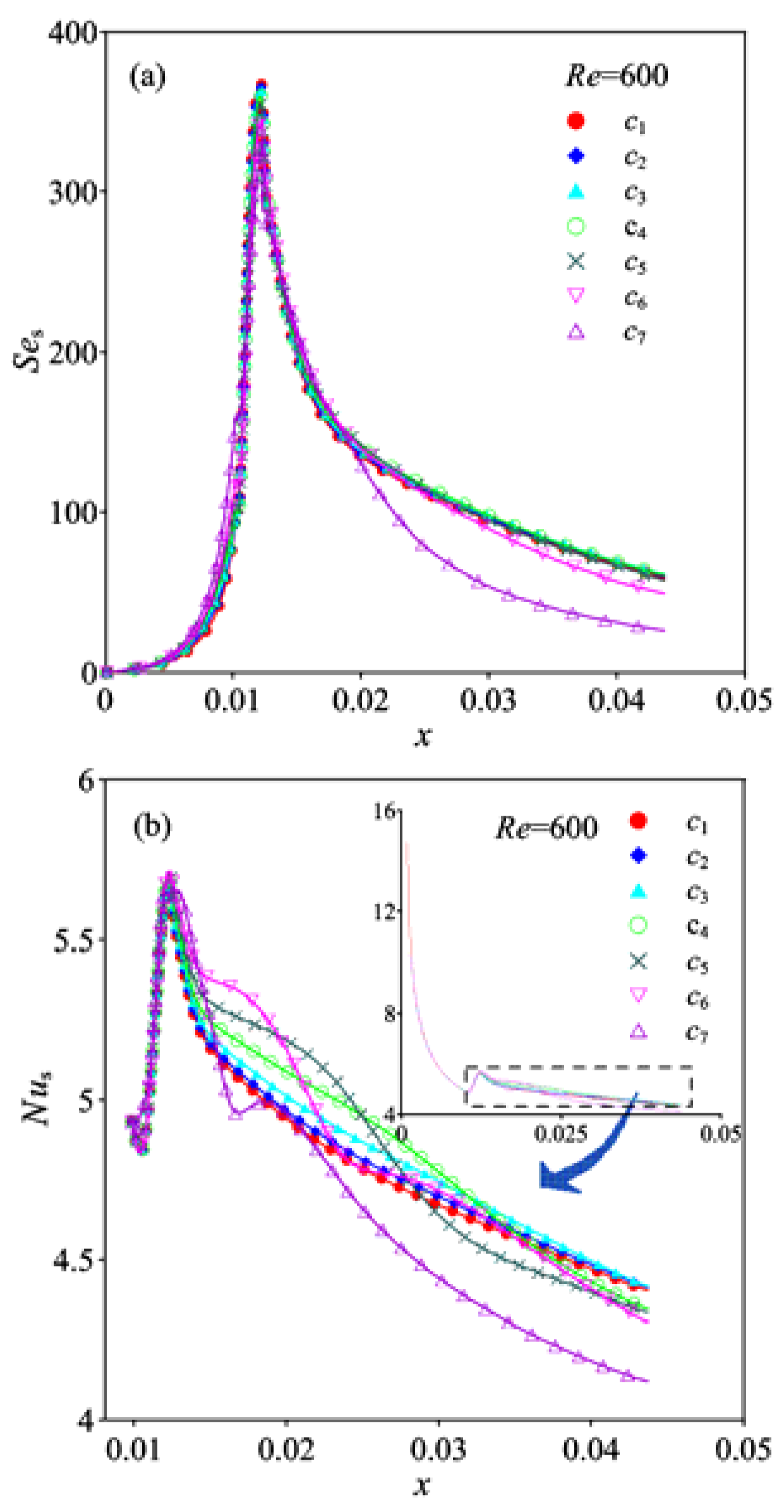
3.2. Distributions of the Span-Average Values of Ses and Nus

The span-average values of Ses and Nus for different transverse pitches are presented in Figure 8 when Re = 600. Since the fluid at the inlet has uniform velocity, Ses is zero at the inlet. Then, the value of Ses increases slightly in the zone after the entrance because the flow direction changes ahead of the winglet VGs. Longitudinal vortices are generated when the fluid flows over the winglets. Ses increases rapidly from the front point to the winglet trailing end. The peak values of Ses are obtained at the trailing ends of the winglets. Ses decreases quickly behind the winglets due to vortex attenuation, and then Ses decreases gradually until the outlet is reached. In the region around the winglets, a slight difference in Ses for different c values is observed. The differences in Ses are quite obvious between case c7 and the other cases in the region behind the winglets because the vortex interaction is the strongest for c7. Ses generally increases along with the decrease in the vortex interaction, and the Ses value for c7 is the smallest. The differences in Ses between c1 and c5 are slight, and the value of Ses for c4 is the largest.
The span-average value of Nus decreases continuously from the inlet to the front of the winglets due to the development of a boundary layer, as shown in Figure 8b. There is a slight difference in Nus for different c values in the region in front of the winglets. Then, Nus increases sharply in the winglet locations. Peak values of Nus are obtained around the winglet trailing end owing to the occurrence of the largest vortex intensity, as shown in Figure 8a. Nus decreases quickly immediately behind the winglets and then gradually decreases until the outlet is reached due to the attenuation of the longitudinal vortices. Nus increases slightly when c ranges from c1 to c3 owing to the formation of a common flow region with a decrease in the transverse pitch between the winglets. Vortices start to interact when the transverse pitch of the winglets is c4. An obvious difference in Nus exists between c4 and c7. Since the common flow region is beneficial to heat transfer [17], the local value of Nus generally increases in the short region behind the winglets, and the region length with a large value of Nus decreases, with c changing from c4 to c6. This is because the interaction between the vortices increases with c changing from c4 to c6, and the intensity of the vortices attenuates rapidly in the downstream region. Thus, Nus decreases when the transverse pitch decreases from c4 to c6 in the later part of the simulated channel. For c7, the vortex interaction is the strongest, and the vortex attenuates rapidly, while Nus is the smallest.

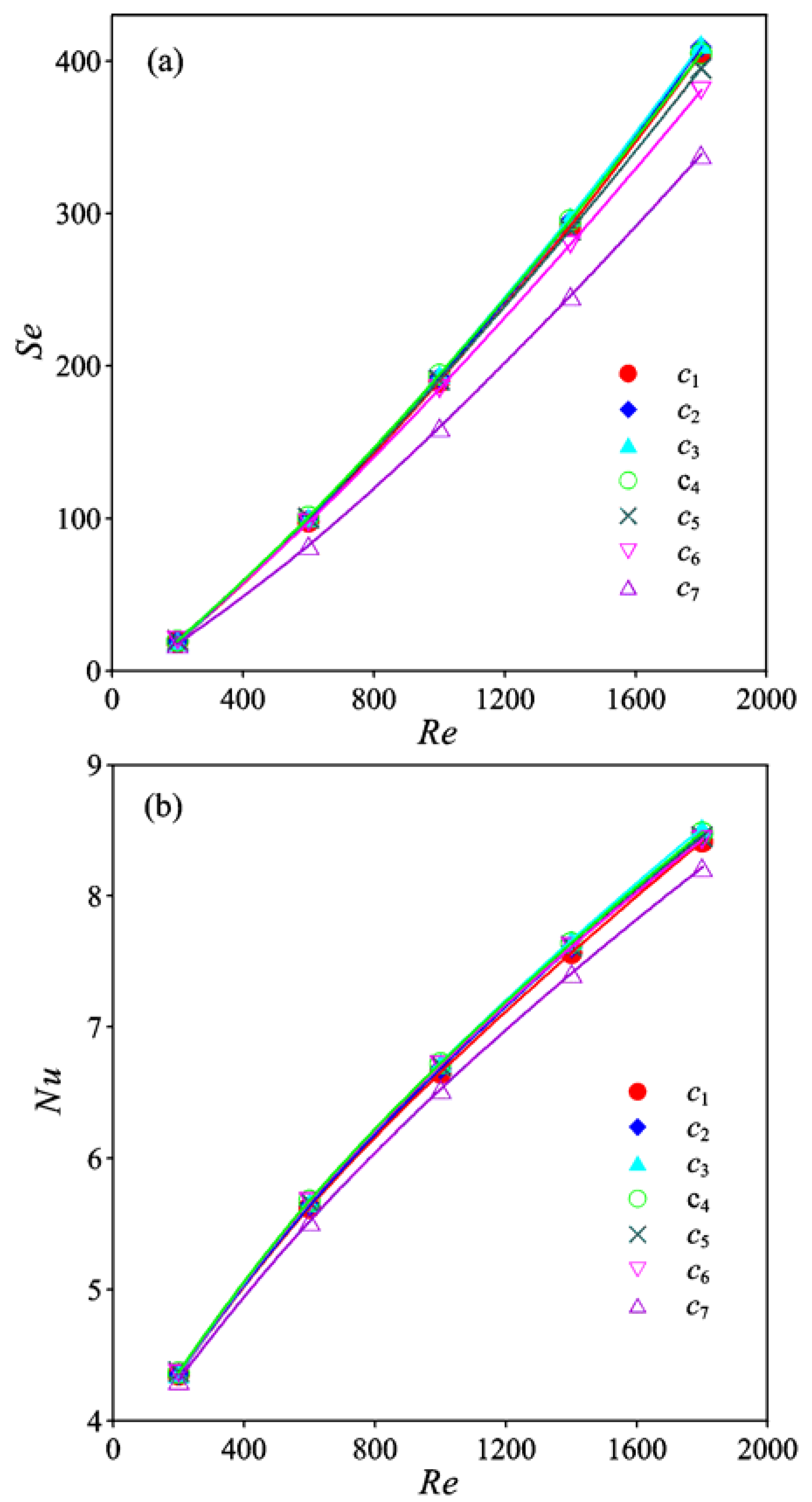
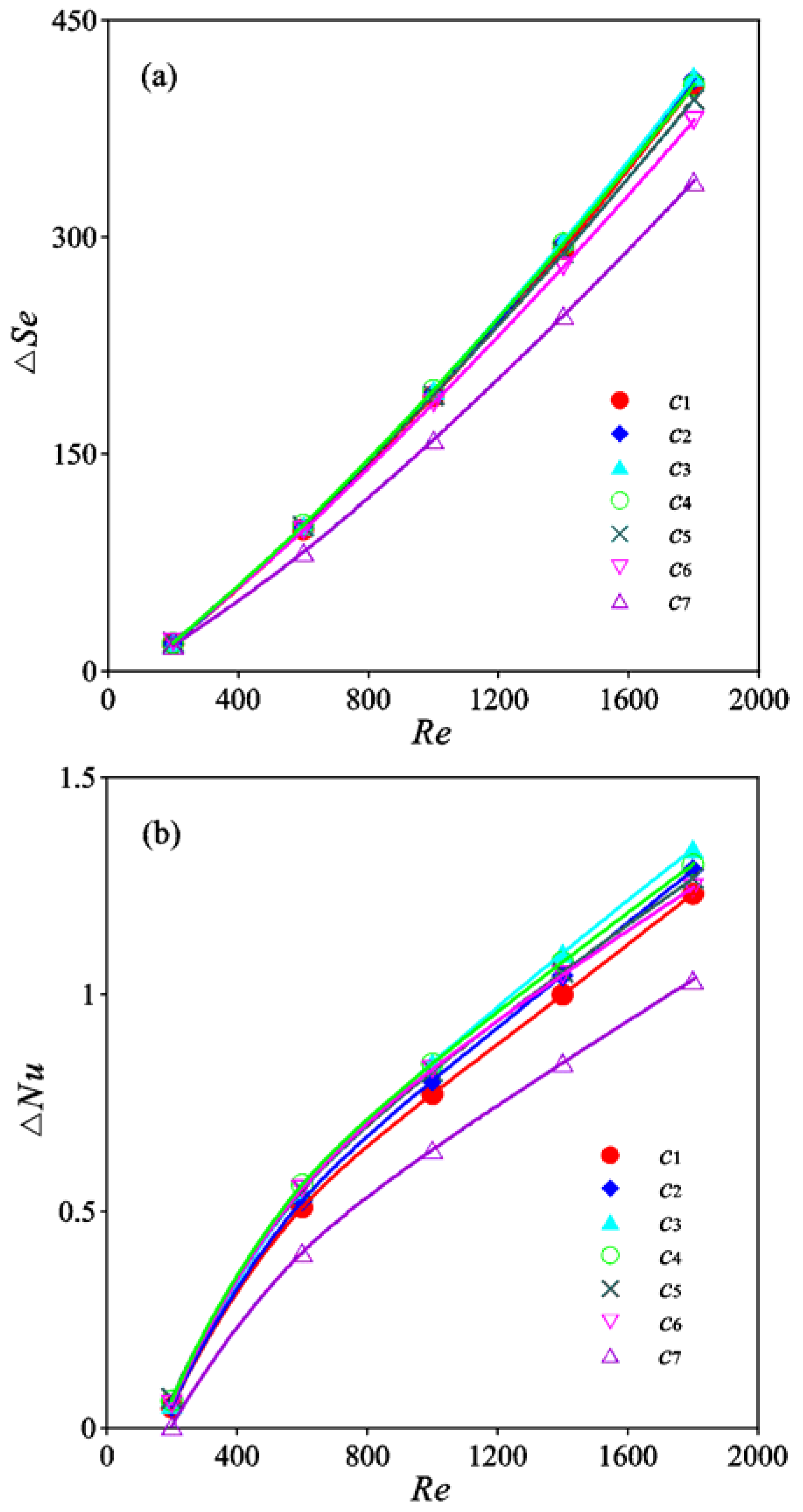
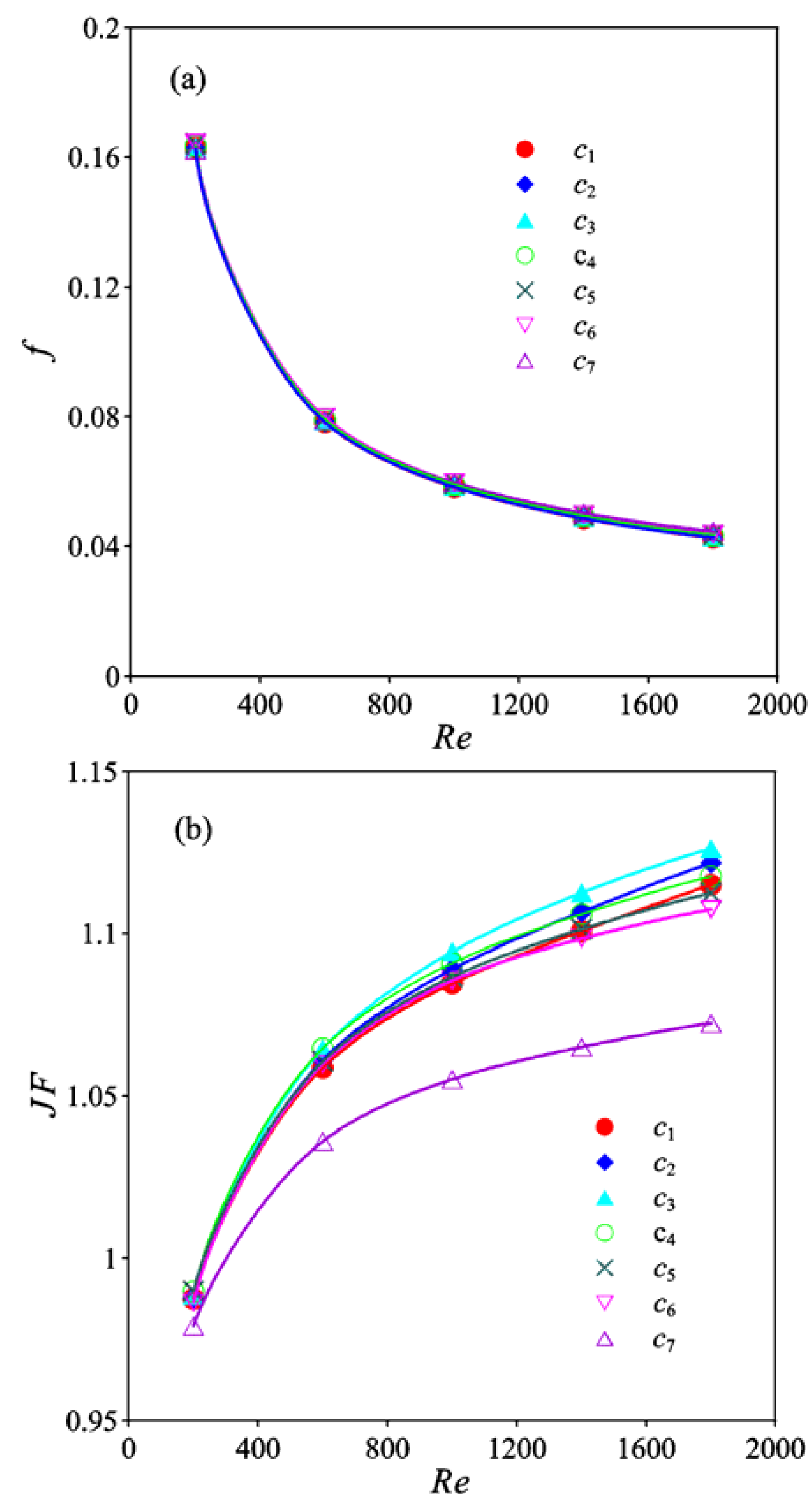
3.3. Distributions of Se, Nu, f and JF

The results of the examination of the effect of the transverse pitch of the winglet VGs on the average Se and Nu are shown in Figure 9. Both Se and Nu increase with increasing Re. The differences in Se for different c values are small, and Se is nearly the same for a small Re of 200. When c = c7, Se has the minimum value owing to the occurrence of the strongest vortex interaction. There is a clear difference in Se between the c7 case and other cases. The difference between the Se values for different cases decreases with increasing transverse pitch owing to the decreasing strength of the vortex interaction. The difference in Se for cases other than c6 and c7 is quite slight, and the value of Se for c3 is the largest. Se for c3 is approximately 21.4% larger than Se for c7.
The transverse pitch of the VGs has a similar effect on Nu as that on Se. As shown in Figure 9b, Nu for c7 is the smallest compared to that for the other cases because of the occurrence of the strongest vortex interaction. The differences in Nu for the other cases are slight, and the value of Nu for c3 is slightly larger than that for the other cases. Nu for c3 is approximately 3.7% higher than that for c7. In the present study, only one pair of winglets were present in the channel, while there are always many winglets on the fin in real applications in heat exchangers; therefore, a considerable increase in Nu can be obtained in the practical application by considering the interactions between the vortices and by optimizing the transverse pitch.
The increments of Se and Nu compared with the corresponding smooth channel without VGs, which are denoted as ΔSe and ΔNu, are shown in Figure 10. Both ΔSe and ΔNu increase with increasing Re. The values of ΔSe and ΔNu are quite small because the longitudinal vortex is weak and has only a slight effect on the heat transfer improvement for small Re values. A clear difference in ΔSe between cases c6 and c7 is observed owing to the considerable vortex interaction and the attenuation of vortex intensity. The difference in ΔSe for the other cases is small. ΔSe for c7 and c3 has the smallest and largest values, respectively. The largest ΔSe for c3 is approximately 21.4% higher than ΔSe for c7. The difference in ΔNu between c1 and c6 is much smaller than that between c6 and c7 owing to the largest difference in Se caused by the vortex interaction. Similar to ΔSe, ΔNu for c7 is also the smallest. ΔNu for c3 is the largest due to the occurrence of the largest vortex intensity and the common flow structure. ΔNu for c3 is increased by 29.2% compared with that for c7 when Re = 1800.
Marginal differences in f are observed for different transverse pitches, as shown in Figure 11a. Thus, the transverse pitch of the vortex generator has a slight effect on the friction factor. The thermal performance can be optimized by changing the transverse pitch of the winglets without a corresponding comparable increase in the pressure penalty.
The thermal performance factor [19,27,28,29,30] defined in Equation (13) reflects the thermal performance enhancement for different transverse pitch values of the winglets compared with the corresponding model without the winglets.
J F = N u / f 1 / 3 N u 0 / f 0 1 / 3
The value of JF is greater than 1.0 when Re > 400, as shown in Figure 11b. JF > 1 means that the heat transfer is improved by the vortex generators under the same pump power. The difference in JF is small when Re is less than 400 owing to the thick boundary layer. Additionally, the longitudinal vortices are quite weak for small flow velocities, and the longitudinal vortices have a limited effect on the heat transfer enhancement. A clear difference in JF is observed between the different transverse pitches of the winglets for large values of Re, and the difference increases with increasing Re. JF first increases slightly when the transverse pitch changes from c1 to c3 and then decreases with a further decrease in the transverse pitch from c3 to c7. The value of JF for case c7 is the smallest owing to the occurrence of the strongest vortex interaction. There is a large difference in JF between cases c7 and c6. Meanwhile, for other cases, the differences in JF are much smaller than the difference between cases c7 and c6. JF is the largest for case c3 due to the weak interaction between the vortices and the formation of the common flow region, which is beneficial for heat transfer. The largest value of JF for case c3 is approximately 5.0% larger than that for case c7. In real applications, such as a fin with VGs for a plate-fin heat exchanger, many pairs of VGs are present on the fin surfaces. Since only a single pair of winglet VGs is used in our simulation, it is clear that increased enhancement of the heat transfer performance will be obtained by optimizing the transverse pitch between the VGs in real applications.

4. Conclusions

The effect of the transverse pitch of a pair of winglet VGs arranged in common flow-up configuration on the symmetrical flow structure and the thermal performance were numerically examined. The main conclusions are:
(1)
The distribution of the longitudinal vortices of the winglet VGs pair has a perfect flow symmetry on the cross-section, and the symmetrical vortex structure is affected by the vortex interaction. The largest vortex intensity of c3 is approximately 21.4% larger than that of c7.
(2)
The transverse pitch of the winglet VGs strongly affects the vortex interaction and heat transfer performance, while the difference in the friction factor is slight. The increment of Nu for c3 is approximately 29.2% larger than that for c7. Thus, thermal performance can be strongly enhanced by optimizing the transverse pitch and the interaction between the longitudinal vortices.
(3)
An optimal transverse pitch exists for the studied configuration of winglet VGs in terms of the highest thermal performance factor. JF for the transverse pitch c3 is the largest and is approximately 5.0% larger than that for c7.

Author Contributions

Conceptualization and methodology, K.S.; formal analysis, K.S., L.W.; writing—original draft preparation, K.S., L.W.; writing—review and editing, K.S., Y.H. and Q.L.; supervision, K.S. All authors have read and agreed to the published version of the manuscript.

Funding

This research was funded by the National Natural Science Foundation of China, Grant number 51866007; the Gansu Provincial Natural Science Foundation, grant number 17JR5RA092.

Acknowledgments

Supported by the Collaborative Innovation Team Project (2018C-13) and the Foundation of a hundred youth talents training program of Lanzhou Jiaotong University.

Conflicts of Interest

The authors declare no conflict of interest.

Nomenclature

ACross-section area (m2)
Bwidth of simulation domain (m)
cpspecific heat at constant pressure (J/(kg·K))
dhhydraulic diameter (m)
Dlocation of VG from inlet (m)
ffriction factor (−)
tpfin spacing
Hvortex generator height (m)
JFsurface goodness factor (−)
Llength of simulation domain (m)
NuNusselt number (−)
Nusspan-average Nusselt number (−)
ppressure (Pa)
ReReynolds number (−)
Sheat transfer area (m2)
Sesecondary flow intensity (−)
Sesbulk secondary flow intensity at position x (−)
Ttemperature (K)
T0constant temperature at inlet (K)
Tsbulk temperature at position x (K)
Twfin surface temperature (K)
Uscharacteristic velocity of secondary flow (m/s)
u, v, wcomponent of velocity (m/s)
u0constant average velocity at inlet (m/s)
umaverage velocity (m/s)
Greek letters
θangle of attack of VG (°)
λthermal conductivity (W/(m·K))
μviscosity (kg/(m·s))
ρdensity (kg/m3)
ωnvorticity along main flow direction (1/s)

References

  1. Tao, W.Q. Numerical Heat Transfer, 2nd ed.; Xi’an Jiaotong University Press: Xi’an, China, 2001. [Google Scholar]
  2. Joardar, A.; Jacobi, A.M. Impact of leading edge delta-wing vortex generators on the thermal performance of a flat tube, louvered-fin compact heat exchanger. Int. J. Heat Mass Transf. 2005, 48, 1480–1493. [Google Scholar] [CrossRef]
  3. Joardar, A.; Jacobi, A.M. Heat transfer enhancement by winglet-type vortex generator arrays in compact plain-fin-and-tube heat exchangers. Int. J. Refrig. 2008, 31, 87–97. [Google Scholar] [CrossRef]
  4. Joardar, A.; Jacobi, A.M. A Numerical Study of Flow and Heat Transfer Enhancement Using an Array of Delta-Winglet Vortex Generators in a Fin-and-Tube Heat Exchanger. J. Heat Transf. 2007, 129, 1156–1167. [Google Scholar] [CrossRef]
  5. Jacobi, A.M.; Shah, R.K. Heat transfer surface enhancement through the use of longitudinal vortices: A review of recent progress. Exp. Therm. Fluid Sci. 1995, 11, 295–309. [Google Scholar] [CrossRef]
  6. Biswas, G.; Deb, P.; Biswas, S. Generation of longitudinal streamwise vortices—A device for improving heat exchanger design. Heat Transf. 1994, 116, 588–597. [Google Scholar] [CrossRef]
  7. Fiebig, M. Vortices and heat transfer. J. Appl. Math. Mech. 1977, 77, 3–18. [Google Scholar] [CrossRef]
  8. Fiebig, M. Vortex generators for compact heat exchangers. Enhanc. Heat Transf. 1995, 2, 43–61. [Google Scholar] [CrossRef]
  9. Song, K.W.; Wang, Y.; Zhang, Q.; Wang, L.B.; Liu, Y.J. Numerical study of the fin efficiency and a modified fin efficiency formula for flat tube bank fin heat exchanger. Int. J. Heat Mass Transf. 2011, 54, 2661–2672. [Google Scholar] [CrossRef]
  10. Liu, S.; Wang, L.; Fan, J.; Zhang, Y.; Dong, Y.; Song, K. Tube transverse pitch effect on heat/mass transfer characteristics of flat tube bank fin mounted with vortex generators. J. Heat Transf. 2008, 130, 064502. [Google Scholar] [CrossRef]
  11. Song, K.W.; Wang, L.B. Relationship between heat transfer intensity and absolute vorticity flux intensity in flat tube bank fin channels with Vortex Generators. Prog. Comput. Fluid Dyn. 2008, 8, 496–502. [Google Scholar] [CrossRef]
  12. Wu, J.M.; Tao, W.Q. Numerical study on laminar convection heat transfer in a channel with longitudinal vortex generator part B: Parametric study of major influences factors. Int. J. Heat Mass Transf. 2008, 51, 3683–3692. [Google Scholar] [CrossRef]
  13. Min, C.H.; Qi, C.Y.; Kong, X.F.; Dong, J.F. Experimental study of rectangular channel with modified rectangular longitudinal vortex generators. Int. J. Heat Mass Transf. 2010, 53, 3023–3029. [Google Scholar] [CrossRef]
  14. Tian, L.T.; He, Y.L.; Lei, Y.G.; Tao, W.Q. Numerical study of fluid flow and heat transfer in a flat-plate channel with longitudinal vortex generators by applying field synergy principle analysis. Int. Commun. Heat Mass Transf. 2009, 36, 111–120. [Google Scholar] [CrossRef]
  15. Wu, J.M.; Tao, W.Q. Impact of delta winglet vortex generators on the performance of a novel fin-tube surface with two rows of tubes in different diameters. Energy Convers. Manag. 2011, 52, 2895–2901. [Google Scholar] [CrossRef]
  16. Li, M.J.; Zhang, H.; Zhang, J.; Mu, T.; Tian, E.; Dan, D.; Zhang, X.D.; Tao, W.Q. Experimental and numerical study and comparison of performance for wavy fin and a plain fin with radiantly arranged winglets around each tube in fin and-tube heat exchangers. Appl. Therm. Eng. 2018, 133, 298–307. [Google Scholar] [CrossRef]
  17. Naik, H.; Tiwari, S. Effect of winglet location on performance of fin-tube heat exchangers with inline tube arrangement. Int. J. Heat Mass Transf. 2018, 125, 248–261. [Google Scholar] [CrossRef]
  18. Song, K.W.; Xi, Z.P.; Su, M.; Wang, L.B. Effect of geometric size of curved delta winglet vortex generators and tube pitch on heat transfer characteristics of fin-tube heat exchanger. Exp. Therm. Fluid Sci. 2017, 82, 8–18. [Google Scholar] [CrossRef]
  19. Song, K.W.; Tagawa, T.; Chen, Z.H.; Zhang, Q. Heat transfer characteristics of concave and convex curved vortex generators in the channel of plate heat exchanger under laminar flow. Int. J. Therm. Sci. 2019, 137, 215–228. [Google Scholar] [CrossRef]
  20. Lu, G.F.; Zhai, X.Q. Effects of curved vortex generators on the air-side performance of fin-and-tube heat exchangers. Int. J. Therm. Sci. 2019, 136, 509–518. [Google Scholar] [CrossRef]
  21. Han, H.; Wang, S.; Sun, W.L.; Li, Y.; Wang, S. Numerical study of thermal and flow characteristics for a fin-and-tube heat exchanger with arc winglet type vortex generators. Int. J. Refrig. 2019, 98, 61–69. [Google Scholar] [CrossRef]
  22. Lu, G.F.; Zhai, X.Q. Analysis on heat transfer and pressure drop of fin-and-oval-tube heat exchangers with tear-drop delta vortex generators. Int. J. Heat Mass Transf. 2018, 127, 1054–1063. [Google Scholar] [CrossRef]
  23. Sarangi, S.K.; Mishra, D.P. Effect of winglet location on heat transfer of a fin-and-tube heat exchanger. Appl. Therm. Eng. 2017, 116, 528–540. [Google Scholar] [CrossRef]
  24. Song, K.W.; Wang, L.B. The effectiveness of secondary flow produced by vortex generators mounted on both surfaces of the fin to enhance heat transfer in a flat tube bank fin heat exchanger. ASME J. Heat Transf. 2013, 135, 041902. [Google Scholar] [CrossRef]
  25. Song, K.W.; Liu, S.; Wang, L.B. Interaction of counter rotating longitudinal vortices and the effect on fluid flow and heat transfer. Int. J. Heat Mass Transf. 2016, 93, 349–360. [Google Scholar] [CrossRef]
  26. Song, K.W.; Hu, W.L.; Liu, S.; Wang, L.B. Quantitative relationship between secondary flow intensity and heat transfer intensity in flat-tube-and-fin air heat exchanger with vortex generators. Appl. Therm. Eng. 2016, 103, 1064–1070. [Google Scholar] [CrossRef]
  27. Song, K.W.; Wang, L.B. Effects of longitudinal vortex interaction on periodically developed flow and heat transfer of fin-and-tube heat exchanger. Int. J. Therm. Sci. 2016, 109, 206–216. [Google Scholar] [CrossRef]
  28. Song, K.W.; Tagawa, T. The optimal arrangement of vortex generators for best heat transfer enhancement in flat-tube-fin heat exchanger. Int. J. Therm. Sci. 2018, 132, 355–367. [Google Scholar] [CrossRef]
  29. Song, K.W.; Shi, W.N.; Wu, X.; Wang, L.B. Characteristics of flow symmetry and heat transfer of winglet pair in common flow down configuration. Symmetry 2020, 12, 209. [Google Scholar] [CrossRef] [Green Version]
  30. Luo, C.; Wu, S.; Song, K.W.; Hua, L.; Wang, L.B. Thermo-hydraulic performance optimization of wavy fin heat exchanger by combining delta winglet vortex generators. Appl. Therm. Eng. 2019, 163, 114343. [Google Scholar] [CrossRef]
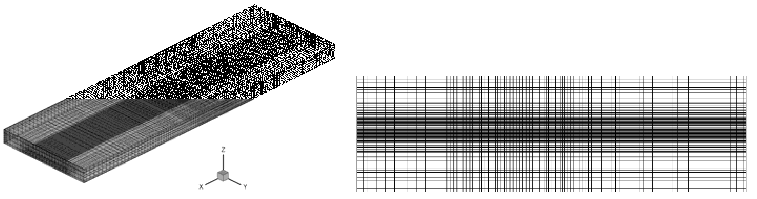
Figure 1. Physical model and arrangement of winglet VGs. (a) physical model, (b) front view, (c) top view, (d) side view, (e) cross sections.
Symmetry 12 00247 g001
Figure 2. Grid system.
Symmetry 12 00247 g002
Figure 3. Comparison of results with Tian et al. [14].
Symmetry 12 00247 g003
Figure 4. Distribution of vortices on the cross-sections for c3.
Symmetry 12 00247 g004
Figure 5. Longitudinal vortices for different transverse pitches on s4.
Symmetry 12 00247 g005
Figure 6. Distribution of Se on cross-sections for c3.
Symmetry 12 00247 g006
Figure 7. Distribution of Se for different transverse pitches on s4.
Symmetry 12 00247 g007
Figure 8. Distribution of Ses and Nus for different transverse pitches. (a) Ses, (b) Nus.
Symmetry 12 00247 g008
Figure 9. Comparison of Se and Nu, (a) Se, (b) Nu.
Symmetry 12 00247 g009
Figure 10. Comparison of ΔSe and ΔNu, (a) ΔSe, (b) ΔNu.
Symmetry 12 00247 g010
Figure 11. Comparison of f and JF, (a) f, (b) JF.
Symmetry 12 00247 g011
Table 1. Grid independence test.
No.Grid (x × y × z)NuRelative ErrorfRelative Error
1140 × 118 × 266.7380.18%5.864 × 10−20.14%
2194 × 142 × 326.726-5.856 × 10⁻²-
3234 × 168 × 376.7390.19%5.896 × 10−20.68%

