Abstract
The effect of transverse pitch between a pair of delta-winglet vortex generators arranged in a common flow down configuration on the symmetrical flow structure and heat-transfer performance was numerically investigated. The results showed that symmetrical longitudinal vortices form a common flow down region between the vortices. The fluid is induced to flow from the top towards the bottom of the channel in the common flow region, which is advantageous to the heat transfer of the bottom fin. The vortex interaction increases and the vortex intensity decreases along with the decrease in transverse pitch of vortex generators. Vortex interaction has a slight influence on pressure penalty. The Nusselt number decreases with increasing vortex interaction. The vortices gradually attenuate and depart from each other during the process of flowing downward. A reasonable transverse pitch of delta-winglet vortex generators in a common-flow-down configuration is recommended for high thermal performance.
1. Introduction
Improvement of the heat-transfer efficiency can decrease the size, weight, and cost of heat exchangers. The thermal performance of fins can be improved by a longitudinal vortex combined with low pressure loss. Vortex generators (VGs) are widely applied as the longitudinal vortex producer in heat exchangers and computational fluid dynamics is the most efficient method for the design and optimization of complex heat exchangers [1,2,3,4,5,6,7,8,9,10,11,12,13,14]. Meng et al. [5] numerically analyzed the influence of multiple longitudinal vortices on thermal performance. The results showed that the heat transfer is significantly enhanced with a similar increase in flow resistance. Wu and Tao [6] stated that improvement in thermal performance can be obtained through optimization of VG parameters. Song et al. [7,8] reported that the VGs arranged on both fin surfaces of the flow channel can simultaneously increase heat transfer and decrease pressure loss compared with the plane VG under the same VG area. Lei et al. [9] studied the in-line and staggered tube-fin heat exchangers with VGs and found that the heat transfer increment is greater than the increase in resistance. Samadifar and Toghraie [10] studied several new-type VGs and found that the best VG attack angle was 45 degrees. Luo et al. [11] proposed a new combination of VGs and a wavy fin. A considerable increase in thermal performance was reported compared with the normal wavy fin. Li et al. [12] experimentally studied a fin with radiantly arranged VGs and showed that the fin with radiantly arranged VGs had a better comprehensive performance. Song et al. [14] summarized different geometric shapes of VGs in the open literature and found that the concave-curved VG had better thermal performance than the normal-plane VG. Yang et al. [15] reported that wedge-shaped VGs can lead to an increase in volume-goodness factor of up to 30% compared with the dimple channel without VGs. Silva et al. [13] studied the application of VGs in solar collectors and found that the heat transfer was effectively enhanced by the VGs.
VGs are usually arranged in pairs in real applications due to the common flow which is beneficial to heat-transfer improvement. Gupta et al. [16] reported a heat transfer increase of 34% by the VGs with holes arranged in common-flow-up configuration compared with the corresponding case without VGs. Skullong et al. [17] studied the rectangular and trapezoidal VG pairs punched with holes and great heat transfer enhancement was obtained by the trapezoidal VGs due to the downward common vortex flow to the solar absorber plate. Sinha et al. [18] studied the effect of combined VG arrays with different configurations on the performance of a plate-fin heat exchanger. Tian et al. [19] analyzed the influence of different VG arrangements on heat transfer. The results showed that the heat transfer and the flow resistance of the channel with VGs arranged in common flow down are greater than that in the common flow up configuration. Yang et al. [20] studied the influence of VGs in common flow down on the thermal hydraulic performance. Their research showed that the heat transfer is enhanced due to the longitudinal vortex. Sarangi and Mishra [21] studied the location of VGs in common flow up configuration and reported that the VGs near the central tube were effective at heat-transfer enhancement. Lu and Zhai [22] numerically studied the performance of tear-drop VGs in common flow up. They found that tear-drop VGs can enhance the heat transfer with a negligible increase in the pressure drop.
Although there are many studies about VG pairs in the literature, there is no paper considering the vortex interaction between the pair of longitudinal vortices. The pair of longitudinal vortices will inevitably interact with each other and affect the vortex intensity and heat-transfer performance when the VGs move close to each other. Song et al. [23] quantitatively analyzed the intensity of vortices by a secondary flow intensity parameter Se and found that the vortex intensity increased when an obvious common flow region formed between counter-rotating longitudinal vortices. The effect of vortex interaction on the heat transfer of a flat-tube-fin heat exchanger was reported in [24,25]. The results showed that an optimal arrangement of VGs exists for the best heat-transfer enhancement by considering the vortex interaction.
As the vortex interaction significantly affects the heat transfer, it is meaningful to study the vortex interaction to find the optimal transverse pitch of a pair of VGs for the highest thermal performance. In this paper, the vortex interaction between a pair of VGs in a common flow down configuration was numerically studied. The effect of the vortex interaction on the flow symmetry and thermal performance was discussed in detail.
2. Physical Model, Methods, and Formulations
The schematic view of the studied physical model is shown in Figure 1. Two winglet VGs were arranged in a common flow down configuration with a transverse pitch of c. The vortex generator had a height of H = 1.4 mm. The VG baseline equaled 2H. The VG attack angle was θ = 35°. The studied transverse pitches between VGs, as shown in Figure 2 and Table 1, were named c1 to c6 with the ratio of c/(2Hsinθ) = 2.5, 2.0, 1.5, 1.0, 0.5, and 0.0, respectively. The channel width and length were B = 10H and L = 31.5H, respectively. The net height of the channel was Fp = 2 mm. The VGs were symmetrical around the center with a distance of D = 10 mm from the inlet. The wall temperature was kept at 80 degrees centigrade and the fluid inlet temperature was 40 degrees centigrade. The properties of the fluid of air were assumed as constant under the mean temperature of 60 degrees centigrade.
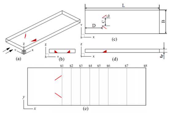
Figure 1.
Physical model and cross sections. (a) physical model; (b) front view; (c) top view; (d) side view; (e) cross sections.
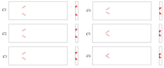
Figure 2.
Arrangement of vortex generators (VGs) with different transverse pitches of VGs.

Table 1.
Transverse pitches of VGs.
Steady and incompressible laminar flow was considered without considering the volume force and viscosity dissipation. The governing equations were as follows [14].
Boundary conditions:
At the inlet:
At the outlet:
At the symmetric side surfaces:
At the solid surfaces:
The hydraulic diameter was selected as the fin spacing. The parameters were defined as follows:
The average temperature on the cross section was:
Span average Nusselt number (Nus) on the fin surfaces:
The secondary flow intensity [7,23,24,25]:
The secondary flow characteristic speed [7,23]:
where ωn was the vortex flux along the main flow direction.
The thermal performance factor [14,23] was defined as:
The above governing equations were discretized by the second-order central difference scheme in the control volume and solved by the code written by FORTRAN. The velocity and pressure were coupled using the SIMPLE algorithm [26]. The relaxation factors for velocity, pressure, and temperature were 0.6, 0.5, and 0.4, respectively. The iteration of the governing equations was first run for a thousand steps and then convergence was judged with a residual of 10−6 for the equations when the relative errors of Nu, f, and T between every 200 iterations were less than 0.01%.
The grid independence was tested out between three different structured grid numbers, 138 × 114 × 24, 194 × 142 × 32, and 234 × 166 × 38 at Re = 1000 and c3 = 2, as shown in Table 2. The differences in Nu and f between the neighboring grids were smaller than 1%. Thus, the numerical results are not dependent on the grid number. The medium-size grid 194 × 142 × 32 was adopted to obtain the numerical results in the present paper. The mesh of the model is shown in Figure 3.
Table 2.
Grid independence test.
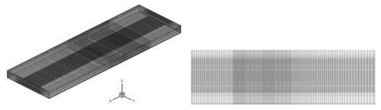
Figure 3.
Grid system.
The numerical method and code were validated using a comparison with the results of Tian et al. [27]. The model for comparison was formed by two parallel fins mounted with a pair of winglet vortex generators in a common flow down configuration. The comparisons of Nu and f are presented in Figure 4. The numerical results agreed with the results reported in the literature. The largest difference in Nu was less than 2.9% and the largest difference in f was less than 1.8% in the studied range of Re. Thus, the numerical method and code were reliable.
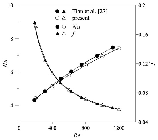
Figure 4.
Comparison of present results with Tian et al. [27].
3. Results and Discussions
3.1. Longitudinal Vortices on the Cross Sections
Eight cross sections marked as s1 to s8, as shown in Figure 1e, were selected to show the development of longitudinal vortices in the channel. The distributions of longitudinal vortices are shown in Figure 5. The transverse pitch of the VGs is c5 and Re is 1800 in Figure 5. The vortices were located near the bottom fin because the VGs were arranged on the bottom fin. The longitudinal vortices rotated in counter-rotating directions and there was a symmetrical vortex-flow structure on the cross sections. The fluid was induced to flow from the top fin towards the bottom fin of the channel in the common-flow region. Thus, the arrangement of VGs was always called a common flow down configuration. The vortex intensity was the strongest in the region around the VG and the vortex intensity gradually decreased along the flow direction. There was an obvious vortex interaction on cross section s1 owing to the small distance between the strong vortices. The longitudinal vortices attenuated and the distance between the symmetrical vortices gradually increased when the vortices flowed downstream. Thus, the induced flow in the common region became weak and the vortex interaction also decreased.
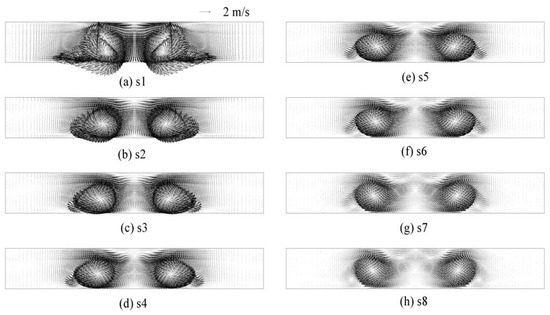
Figure 5.
Longitudinal vortices on cross sections for c5.
Figure 6 shows the vortices on s4 for different transverse pitches when Re = 1800. The distance between the symmetrical vortices decreased with a decreasing transverse pitch of VGs. There was a marginal difference between the symmetrical vortices and the vortices were nearly the same when the transverse pitch changed between c1 and c3. This is because the distance between the symmetrical vortices was large and there was no vortex interaction between the vortices. The intensity of the vortices decreased when the transverse pitch decreased from c4 to c6 due to the increase in vortex interaction. The vortex intensity of c6 is apparently much weaker than that of c5 due to the strongest vortex interaction between the symmetrical vortices.
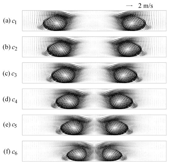
Figure 6.
Distribution of longitudinal vortices on s4 for different c.
3.2. Contour Plot of Vortex Intensity
The distributions of vortex intensity Se corresponding to the same cross sections in Figure 5 are presented in Figure 7 when the transverse pitch between the VGs was c5. The distribution of Se reflected the distribution of longitudinal vortices perfectly. A contour plot of Se corresponding to the symmetrical vortex-flow structure was also symmetrical. A large value of Se was attained in the vortex zone and was located nearer to the bottom fin. The small zones of Se corresponding to the corner vortex were located on the outer sides of the large zones of the main vortices. The intensity of the contour plot of Se gradually decreased from s1 to s8 due to the attenuation of longitudinal vortices and the zones departing from each other. The distribution of Se for different transverse pitches corresponding to Figure 6 is shown in Figure 8. The distance between the main zones of Se decreased with decreasing transverse pitch. Se was almost the same for large transverse pitches between c1 and c3 due to a weak vortex interaction. The contour plot of Se decreased slightly when the transverse pitch decreased from c4 to c5, and Se for c6 was apparently the smallest due to the strongest vortex interaction.
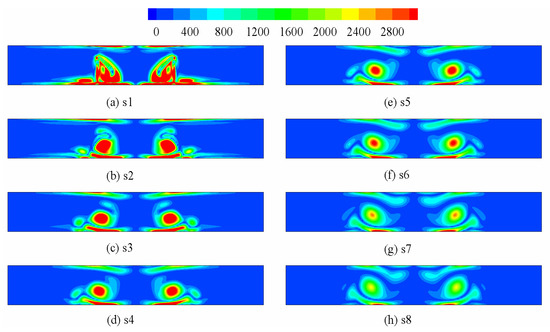
Figure 7.
Distribution of Se on different cross sections for c5.
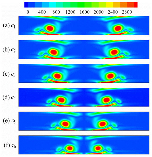
Figure 8.
Distribution of Se on s4 for different transverse pitches of VGs.
3.3. Distribution of Nus and Ses
The longitudinal vortices increased the secondary flow intensity and hence the heat-transfer enhancement. Figure 9 shows the distribution of cross-sectional averaged vortex intensity Ses along the flow direction for different transverse pitches. Ses was zero at the inlet because the fluid was uniform. Ses then gradually increased due to the increase in secondary flow in the channel. In the region near the VG, Ses increased sharply due to the flow separation and the generation of longitudinal vortices. Ses reached the largest value around the trail end and then started to decrease quickly due to the attenuation of longitudinal vortices. Ses then decreased smoothly to the outlet. The differences in Ses were marginal in the region between the inlet and the VGs for different transverse pitches because there was no vortex interaction. In the region behind the VGs, the values of Ses for c1 to c4 were nearly the same while there was an obvious difference for c4 to c6. Ses decreased and attained the smallest value for c6 due to the vortex interaction, as has been discussed above. The distribution of Ses for Re = 1800 was similar with that for Re = 600 and the value of Ses for Re = 1800 was obviously larger than that for Re = 600. The difference in Ses between c5 and c6 increased when Re increased from 600 to 1800. Ses of c6 decreased by up to 23.1% and 26.5% compared with c1 for Re = 600 and 1800, respectively.
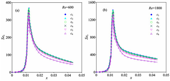
Figure 9.
Distribution of Ses under different transverse pitches of c: (a) Re = 600; (b) Re = 1800.
The distributions of span-averaged Nus for different transverse pitches are shown in Figure 10. The largest value of Nus was obtained at the entrance of the channel due to the forming of a boundary layer, then Nus gradually decreased because of the development of the thermal boundary layer. Just as the values of Ses were nearly the same, the values of Nus were also nearly the same for different transverse pitches in the region between the inlet and the VGs. An obvious difference existed in the region between the VGs and the outlet owing to the vortex interaction. Nus increased quickly in the location of VGs and showed peak values at the trail end of the VGs. Nus decreased from the peak point to the outlet due to the attenuation of the vortices. In the region behind the VGs for a short distance, there was a slight difference in Nus and the value of Nus for c5 was the largest due to the common flow formed between the symmetrical vortices. The difference in Nus between different values of c then increased and Nus generally decreased with the decrease of c. The differences in Nus between the cases between c1 and c4 were slight. Obvious differences existed between the transverse pitches c5 and c6, and Nus of c6 was the minimum due to the smallest vortex intensity. The value of Nus and the difference in Nus increased with the increase of Re from 600 to 1800. The value of Nus of c6 decreased by 3.4% and 7.2% compared with c1 at the outlet for Re = 600 and 1800, respectively.
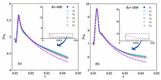
Figure 10.
Distribution of Nus under different transverse pitches of c: (a) Re = 600; (b) Re = 1800.
3.4. Distributions of Nu, Se, f, and JF
The distributions of Se and Nu are presented in Figure 11. When Re was small, the vortex intensity was weak and the values of Se were nearly the same. Se increased with increasing Re and the difference in Se between different cases also increased due to the vortex interaction. The difference in Se was quite slight when the transverse pitch was large between c1 and c4. Obvious differences in Se can be attained for c4 to c6 due to the increase in vortex interaction. Se of c6 decreased by 29.2% compared with c1 at Re = 1800. The values of Nu were nearly the same when Re was small at Re = 200, as shown in Figure 11a. Nu was enhanced by the VGs and the difference in Nu between the model with VGs and the plain fin increased with increasing Re. The difference in Nu between different c was slight and an obvious difference in Nu only existed between c5 and c6 due to the decrease in vortex intensity caused by the vortex interaction. Nu of c6 was the smallest and Nu decreased by about 2.0% compared with c1 at Re = 1800. Although there was also an obvious vortex interaction for c5, the formation of common flow down flow structure was beneficial for heat transfer, and as a result the value of Nu for c5 was slightly different to other cases, except c6.
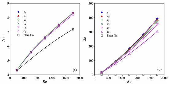
Figure 11.
(a) Distribution of Nu; (b) Distribution of Se.
Figure 12 shows the distributions of f and JF in the Re range between 200 and 1800. f of the model with VGs was obviously larger than that of the plain fin. The values of f for different transverse pitches were nearly the same. Thus, the change of c had no influence on f. The values of JF were less than 1.0 for Re = 200. This is because the vortices were too weak when Re was small at 200, while the pressure loss was increased compared with the plain fin. JF increased quickly from Re = 200 to Re = 600 and then gradually increased from Re = 600 to Re = 1800. The difference in JF was slight for c1 to c4. There was an obvious difference in JF for c4 to c6. JF of c6 was the smallest and was apparently smaller than that of c5. Thus, VG pairs in a common flow down configuration should be arranged with the transverse pitch greater than c5 = 0.5 in order to obtain high thermal performance.

Figure 12.
(a) Distribution of f; (b) Distribution of JF.
4. Conclusions
The symmetrical flow structure of the longitudinal vortices generated by VG pairs in a common flow down configuration and the influence of vortex interaction on thermal performance were numerically reported. The main conclusions can be summarized as follows:
- The symmetrical longitudinal vortices form a common-flow region between the vortices and the fluid is induced to flow from the top towards the bottom of the channel, which is beneficial for the heat transfer of the bottom fin;
- The vortex interaction in the symmetrical common-flow region increases with decreasing transverse pitch of the VG pair. The vortex intensity is obviously affected by the vortex interaction, while the friction factor is not influenced by the transverse pitch of the VG pair and the values of f for different transverse pitches are nearly the same;
- The vortex intensity, heat transfer, and thermal performance factor are obviously decreased when the transverse pitch of the studied VGs is smaller than a certain value of c5. VG pairs in a common flow down configuration should be arranged with the transverse pitch greater than c5 = 0.5 in order to obtain high thermal performance.
Author Contributions
Conceptualization, K.S.; formal analysis, W.S. and X.W.; methodology, K.S. and L.W.; writing—original draft, K.S. and W.S.; writing—review and editing, K.S. All authors have read and agreed to the published version of the manuscript.
Acknowledgments
This research was funded by the National Natural Science Foundation of China, Grant number 51866007; Collaborative Innovation Team Project (2018C-13) and the Foundation of a Hundred Youth Talents Training Program of Lanzhou Jiaotong University; and the Gansu Provincial Natural Science Foundation, grant number 17JR5RA092.
Conflicts of Interest
The authors declare no conflict of interest.
Nomenclature
| A | cross section area (m2) |
| B | width of simulation domain (m) |
| cp | specific heat at constant pressure (J/(kg·K)) |
| dh | hydraulic diameter (m) |
| D | location of VG from inlet (m) |
| f | friction factor (−) |
| Fp | fin spacing (m) |
| H | vortex generator height (m) |
| JF | surface goodness factor (−) |
| L | length of simulation domain (m) |
| Nu | Nusselt number (−) |
| Nulocal | local Nusselt number on fin surface (−) |
| Nus | span-average Nusselt number (−) |
| p | pressure (Pa) |
| Re | Reynolds number (−) |
| S | heat transfer area (m2) |
| Se | secondary flow intensity (−) |
| Ses | bulk secondary flow intensity at position x (−) |
| T | temperature (K) |
| Ts | bulk temperature at position x (K) |
| Tw | fin surface temperature (K) |
| Us | characteristic velocity of secondary flow (m/s) |
| u,v,w | component of velocity (m/s) |
| u0 | average inlet velocity (m/s) |
| um | cross sectional average velocity (m/s) |
| Greek letters | |
| θ | angle of attack of VG (°) |
| λ | thermal conductivity (W/(m·K)) |
| μ | viscosity (kg/(m·s)) |
| ρ | density (kg/m3) |
| ωn | vorticity along main flow direction (1/s) |
| Subscripts | |
| in | inlet |
| out | outlet |
References
- Yanagihara, J.I.; Torri, K. Enhancement of laminar boundary layer heat transfer by longitudinal vortices. In Transport Phenomena in Heat and Mass Transfer; Elsevier Science: Sydney, Australia, 1991. [Google Scholar]
- Song, K.; Xi, Z.; Su, M.; Wang, L.; Wu, X.; Wang, L. Effect of geometric size of curved delta winglet vortex generators and tube pitch on heat transfer characteristics of fin-tube heat exchanger. Exp. Therm. Fluid Sci. 2017, 82, 8–18. [Google Scholar] [CrossRef]
- Bhutta Muhammad, M.A.; Hayat, N.; Bashir, M.H.; Khan, A.R.; Ahmad, K.N.; Khan, S. CFD applications in various heat exchangers design: A review. Appl. Therm. Eng. 2012, 32, 1–12. [Google Scholar] [CrossRef]
- Starace, G.; Fiorentino, M.; Longo, M.P.; Carluccio, E. A hybrid method for the cross flow compact heat exchangers design. Appl. Therm. Eng. 2017, 111, 1129–1142. [Google Scholar] [CrossRef]
- Meng, J.A.; Liang, X.G.; Li, Z.h.X. Numerical analysis on the characteristic of turbulent heat transfer with multilongitudinal vortices in tube. J. Eng. Thermophys. 2005, 3, 498–500. [Google Scholar]
- Wu, J.M.; Tao, W.Q. Impact of delta winglet vortex generators on the performance of a novel fin-tube surface with two rows of tubes in different diameters. Energy Convers. Manag. 2011, 52, 2895–2901. [Google Scholar] [CrossRef]
- Song, K.W.; Wang, L.B. The effectiveness of secondary flow produced by vortex generators mounted on both surfaces of the fin to enhance heat transfer in a flat tube bank fin heat exchanger. J. Heat Transf. 2013, 135, 041902. [Google Scholar] [CrossRef]
- Song, K.W.; Wang, L.B.; Sun, D.L. Convective heat transfer and absolute vorticity flux along main flow in a channel formed by flat tube bank fins with vortex generators mounted on both fin surfaces. J. Enhanc. Heat Transf. 2009, 16, 123–139. [Google Scholar] [CrossRef]
- Lei, Y.G.; He, Y.L.; Chu, P.; Tian, L.T. An investigation of the airside performance of fin and tube heat exchangers with delta-winglet. J. Eng. Thermophys. 2010, 31, 94–96. [Google Scholar]
- Samadifar, M.; Toghraie, D. Numerical simulation of heat transfer enhancement in a plate-fin heat exchanger using a new type of vortex generators. Appl. Therm. Eng. 2018, 133, 671–681. [Google Scholar] [CrossRef]
- Luo, C.h.; Wu, S.h.; Song, K.W.; Hua, L.; Wang, L.B. Thermo-hydraulic performance optimization of wavy fin heat exchanger by combining delta winglet vortex generators. Appl. Therm. Eng. 2019, 163, 114343. [Google Scholar] [CrossRef]
- Li, M.J.; Zhang, H.; Zhang, J.; Mu, T.; Tian, E.; Dan, D.; Zhang, X.D.; Tao, W.Q. Experimental and numerical study and comparison of performance for wavy fin and a plain fin with radiantly arranged winglets around each tube in fin and-tube heat exchangers. Appl. Therm. Eng. 2018, 133, 298–307. [Google Scholar] [CrossRef]
- Song, K.W.; Tagawa, T.; Chen, Z.H.; Zhang, Q. Heat transfer characteristics of concave and convex curved vortex generators in the channel of plate heat exchanger under laminar flow. Int. J. Therm. Sci. 2019, 137, 215–228. [Google Scholar] [CrossRef]
- Yang, J.S.; Jeong, M.; Park, Y.G.; Ha, M.Y. Numerical study on the flow and heat transfer characteristics in a dimple cooling channel with a wedge-shaped vortex generator. Int. J. Heat Mass Transf. 2019, 136, 1064–1078. [Google Scholar] [CrossRef]
- Silva, F.A.S.; Dezan, D.J.; Pantaleão, A.V.; Salviano, L.O. Longitudinal vortex generator applied to heat transfer enhancement of a flat plate solar water heater. Appl. Therm. Eng. 2019, 158, 113790. [Google Scholar] [CrossRef]
- Gupta, A.; Roy, A.; Gupta, S.a.c.h.i.n.; Gupta, M. Numerical investigation towards implementation of punched winglet as vortex generator for performance improvement of a fin-and-tube heat exchanger. Int. J. Heat Mass Transf. 2020, 149, 119171. [Google Scholar] [CrossRef]
- Skullong, S.; Promthaisong, P.; Promvonge, P.; Thianpong, C.h.; Pimsarn, M. Thermal performance in solar air heater with perforated-winglet-type vortex generator. Sol. Energy 2018, 170, 1101–1117. [Google Scholar] [CrossRef]
- Sinha, A.; Raman, K.A.; Chattopadhyay, H.; Biswas, G. Effects of different orientations of winglet arrays on the performance of plate-fin heat exchangers. Int. J. Heat Mass Transf. 2013, 57, 202–214. [Google Scholar] [CrossRef]
- Tian, L.T.; Lei, Y.G.; He, Y.L. Heat transfer enhancement in a channel with longitudinal VGs and field synergy principle analysis. J. Eng. Thermophys. 2008, 12, 2128–2130. [Google Scholar]
- Yang, J.S.; Li, D.W.; Choi, G.M. Numerical investigation of fluid flow and heat transfer characteristics by common-flow-up. Int. J. Heat Mass Transf. 2008, 51, 6332–6336. [Google Scholar] [CrossRef]
- Sarangi, S.K.; Mishra, D.P. Effect of winglet location on heat transfer of a fin-and-tube heat exchanger. Appl. Therm. Eng. 2017, 116, 528–540. [Google Scholar] [CrossRef]
- Lu, G.F.; Zhai, X.Q. Analysis on heat transfer and pressure drop of fin-and-oval-tube heat exchangers with tear-drop delta vortex generators. Int. J. Heat Mass Transf. 2018, 127, 1054–1063. [Google Scholar] [CrossRef]
- Song, K.W.; Liu, S.; Wang, L.B. Interaction of counter rotating longitudinal vortices and the effect on fluid flow and heat transfer. Int. J. Heat Mass Transf. 2016, 93, 349–360. [Google Scholar] [CrossRef]
- Song, K.W.; Tagawa, T. The optimal arrangement of vortex generators for best heat transfer enhancement in flat-tube-fin heat exchanger. Int. J. Therm. Sci. 2018, 132, 355–367. [Google Scholar] [CrossRef]
- Song, K.W.; Wang, L.B. Effects of longitudinal vortex interaction on periodically developed flow and heat transfer of fin-and-tube heat exchanger. Int. J. Therm. Sci. 2016, 109, 206–216. [Google Scholar] [CrossRef]
- Tao, W.Q. Numerical Heat Transfer, 2nd ed.; Xi’an Jiaotong University Press: Xi’an, China, 2001. [Google Scholar]
- Tian, L.T.; He, Y.L.; Lei, Y.G.; Tao, W.Q. Numerical study of fluid flow and heat transfer in a flat-plate channel with longitudinal vortex generators by applying field synergy principle analysis. Int. Commun. Heat Mass Tran. 2009, 36, 111–120. [Google Scholar] [CrossRef]
© 2020 by the authors. Licensee MDPI, Basel, Switzerland. This article is an open access article distributed under the terms and conditions of the Creative Commons Attribution (CC BY) license (http://creativecommons.org/licenses/by/4.0/).