Article

Thermal Abuse Behavior of the LIR2450 Micro Coin Cell Battery Having Capacity of 120 mAh with Internal Short Circuit by Penetrating Element

1
Department of Mechanical Engineering, Dong-A University, 37 Nakdong-Daero 550, Saha-gu, Busan 607-714, Korea
2
Ingram School of Engineering, Texas State University, San Marcos, TX 78666, USA
*
Author to whom correspondence should be addressed.
Symmetry 2020, 12(2), 246; https://doi.org/10.3390/sym12020246
Submission received: 8 January 2020 / Revised: 22 January 2020 / Accepted: 2 February 2020 / Published: 5 February 2020
(This article belongs to the Special Issue Heat Transfer in Engineering)

Abstract

:
Internal short circuit in lithium-ion battery by penetrating element leads to exothermic behavior due to accumulated heat. In the present study, investigations are conducted on the thermal behavior of the LIR2450 micro coin cell haivng capacity of 120 mAh, with internal short circuit by penetrating element. The experimental coin cell discharge study was conducted and validated with numerical study within ±5.0%. The effect of penetrating element size, location of penetrating element, state of charge, discharge rate, short-circuit resistance, and heat transfer co-efficient on maximum coin cell temperature and heat generation rate are analyzed. The penetrating element diameters of 0.5, 1.0, 1.5, 2.0, 2.5, 3.0, and 3.5 mm are considered. The effect of initial state of charge (SOC) is considered with 100%, 80%, 60%, and 40%. Three locations for penetrating element are considered with the center, the middle of the radius, and on the edge of the coin cell radius. The different discharge rates of 1C, 2C, 3C, and 4C are considered. The higher-penetrating element size of 3.5 mm with location at the center of the coin cell with 100% SOC showed maximum heat generation rate and maximum temperature of the coin cell. In addition, the optimum value of the dimensionless heat generation rate is obtained at dimensionless short-circuit resistance. The study provides comprehensive insights on the thermal behavior of the lithium-ion cell during thermal abuse condition with internal short circuit by penetrating element.

1. Introduction

Lithium-ion batteries (LIBs) are extensively used in various applications, including from small-scale portable electronics to large-scale application in electric vehicles, along with other applications in the field of drones, airplanes, and robots [1]. LIBs have shown efficient and practical applications in domestic as well as hand-held devices [2]. The LIBs are preferred over other chemistries owing to their strong advantages of high-energy density, low self-discharge, fast charging ability, enhanced cycle life, among many other advantages [3].
However, LIBs are likely to fail in case of over-charging and over-discharging with the possibility of a severe accident in case of overheating or internal-external short circuit [4]. The thermal abuse of LIBs can be caused by penetration, external-short, overheating, or over-charge [5]. In the case of a thermal abuse incident, the available chemical energy in LIBs rapidly converts to heat energy, generating a large amount of heat with the possibility of thermal runaway—fire accompanied by the occasional explosion [6]. Owing to high-energy density and flammable components, LIBs are prone to safety issues. Physical abuse of LIBs could lead to a temperature rise to the levels of 100 to 150 °C, which could trigger cascading exothermic electrochemical reactions along with chemical disintegration, resulting in the rise of temperature to the levels of 500 °C in a few seconds. Although many safety methods, including effective cooling, have been installed, several cases of hazards have been reported over the years [7,8]. The recent events of LIB failure events leading to fire and explosion accidents have focused research attention on LIB safety [9]. For example: iPod caught fire due to overheated LIB [10] and three fire accidents of Boeing 747 at different locations [11]. Although, recently, LIB safety issues have received attention due to increased instances of hazards in electrical vehicle application, the safety concerns were admitted for many years [12,13].
In the case of continuous increase of temperature, rapid reactions start to occur. At around 110 °C, the graphite anode reacts with the electrolyte solvent. At around 165 °C, cathode material decomposes and releases oxygen. At around 180 °C, electrolyte solvent decomposes, and flammable components undergo combustion leading to thermal runaway [14]. The mechanical abuse in terms of penetration, or crush leading to thermal abuse, is an important safety concern and has received increased attention in recent years [15]. In many applications, the overheating and overcharge is controlled as a safe temperature and cut-off voltage are maintained. However, mechanical abuse leading to a short circuit is a challenging threat, as LIB can be subjected to crushing or metal penetration in unpredictable situations, such as accidents. The penetration provides a low-resistance path, drawing extremely high levels of currents with a rapid discharge of available chemical energy and simultaneously converting it into thermal energy. In the absence of resistive load, with the short circuit providing a low-resistance path, the energy is dissipated as joule heat, resulting in a rapid temperature increase [16].
Chen et al. developed an electro-thermal model to investigate the thermal performance during normal discharge and internal short circuit. The authors investigated the effect of an internal short circuit at the center of the battery on the temperature rise of the battery, and suggested that the increasing thermal conductivity of a separator can be an effective method to reduce the heat accumulation at the location of the internal short circuit [17]. Shi et al. conducted an experimental study on the exothermic behavior of LIB under mechanical abuse and suggested that dibenzylamine (DBA) could be used to prevent thermal runaway. The authors suggested that under normal conditions DBA does not affect the battery performance, and during mechanical abuse, DBA is released, which increases electrolyte resistivity preventing thermal runaway [18]. Vyroubal et al. presented a finite element model of nail penetration into the lithium-ion battery and showed that shorting resistance has a significant influence on the cell electrochemical-thermal process of batteries [19]. Noelle investigated internal short circuit on LIB by conducting direct current internal resistance, extremal shorting, and nail penetration experiment, and presented an electrolyte resistance model with experimental validation [20]. Fang et al. developed a 3D electrochemical-thermal model for internal short in Li-ion cell, and predicted that discharge rate was higher in Anode-Aluminum short as compared to Anode-Cathode owing to lower short resistance [21]. Mao et al. investigated the failure mechanism of the lithium-ion battery during nail penetration tests and presented the influence of penetration position and depth on temperature of the jelly-roll-type cylindrical cell. The authors pointed out that maximum temperature was observed when the nail was penetrated at the center of the cylindrical cell with the region of thermal runaway covering the entire cell. According to the micro short-circuit cell model presented by authors, if the temperature reaches between 90–120 °C, heat can spread to whole battery. However, reactions cannot lead to thermal runaway due to the unavailability of oxygen. But if the temperature reaches up to more than 233 °C, then the separator shrinks, thus leading to a larger short-circuit area, with the start of a reaction between cathode and electrolyte releasing a large amount heat and combustion byproducts in terms of gases [22]. Zao et al. conducted external and internal short circuit tests on batteries with different capacities. The authors showed that for external short test, with lower internal resistance, heat was accumulated between clamps and battery tabs, whereas, in case of nail penetration, heat accumulation increases with battery capacity and may catch fire. The authors suggested hydrogel-based thermal management to prevent thermal runaway [23]. There are few studies on how to mitigate the effect of internal short circuit and prevent thermal runaway. For example, Wang et al. suggested a modified current collector with surface-notch, instead of a flat current collector, leading to a negligible temperature increase associated with internal sorting [24]. However, safety concerns still remain for the accumulation of large amounts of heat leading to thermal runaway in LIB during internal short circuit, and more understanding is still needed of the thermal behavior of LIB during internal shorting.
The goal of the present study is to investigate the thermal abuse behavior of the LIR2450 coin cell with internal short circuit by penetrating element. The experimental coin cell discharge study is conducted and validated with numerical study within ±5.0%. The effect of penetrating element size, location of penetrating element, state of charge (SOC), discharge rate, short-circuit resistance, and heat transfer coefficient on maximum temperature and heat generation rate are presented. The study provides comprehensive insights on the thermal behavior of LIBs during thermal abuse condition with internal short circuit by penetrating element.

2. Experimental Study

Figure 1 shows the schematic for the experimental study. The LIB under consideration is the LIR2450 coin cell with 120 mAh capacity, and the specifications of the coin cell are presented in Table 1. The coin cell was connected to KIKUSUI electronic load PLU-150 for evaluating and maintaining current, voltage, and power. The discharge test of the coin cell was conducted under constant current condition. The coin cell was fully charged to 4.2 V and discharge tests were conducted with a cut-off voltage of 2.75 V. The thermocouple was attached to a coin cell positive tab for measuring the surface temperature. The second thermocouple was attached to measure the ambient temperature. All the experiments were conducted in a room set at a constant temperature. The temperature of the room was controlled and kept constant at 25 °C. The details of the equipment used in the experimental study are presented in Table 2.
The measured parameter uncertainty is presented based on the accuracy of the instrument. The measured parameters were voltage, current, and temperature. The accuracy for current measurement was calculated based on Equation (1). The maximum uncertainty in measuring current was 0.45%. The accuracy of the voltage measurement was calculated based on Equation (2). The maximum uncertainty in voltage measurement was 0.08%. The accuracy in temperature measurement was calculated based on Equation (3). The maximum uncertainty in temperature measurement was 1.25%.
I U = ± ( 0.2 %   of   set   +   0.2 %   of   full   scale )   +   V i n / 500 k Ω  
V U = ± ( 0.2 %   of   set   +   0.2 %   of   full   scale )
T U = ± ( 0.1 %   of   reading   +   0.5 ° C )

3. Numerical Model

The numerical model was developed using the MSMD (multi-scale multi-dimensional) model of Ansys Fluent [25]. The LIR2450 coin cell was modeled with radius of 24.5 mm and height of 5 mm. The mesh was generated with 107,478 nodes and 99,552 elements. The geometry and meshing images are provided in Figure 2. The current density, j E c h , was calculated from Equation (4), proposed by Newman, Tiedemann, Gu, and Kim (NTGK) [26] as follows:
j E c h = Q n o min a l Q r e f V o l Y ( U V )
where V is battery cell voltage; Qnominal is the battery capacity in Ampere hours; Qref is the battery capacity used in the experiments to obtain Y and U. Y and U are LIB depth of discharge functions. In the present study, discharge tests were conducted at different constant currents to obtain Y and U functions. The obtained Y and U are fitting parameters with functions of depth of discharge in Equations (5) and (6), as initially suggested by Gu et al. [27]. The values obtained by curve fitting for the 120 mAh LIR2450 coin cell battery are presented in Table 3.
U = a 0 + a 1 ( D O D ) 1 + a 2 ( D O D ) 2 + a 3 ( D O D ) 3 + a 4 ( D O D ) 4 + a 5 ( D O D ) 5
Y = b 0 + b 1 ( D O D ) 1 + b 2 ( D O D ) 2 + b 3 ( D O D ) 3 + b 4 ( D O D ) 4 + b 5 ( D O D ) 5
The thermal- and electrical-coupled field equation for battery operation were solved using Equations (7)–(9) [25], where σ+ and σ are electrical conductivities of the positive and negative electrode, respectively; ϕ+ and ϕ phase potentials for the positive and negative electrodes, respectively; j E C h and q . s h o r t represent volumetric current transfer rate and heat due to electrochemical reaction, respectively; j s h o r t and q . s h o r t represent current transfer rate and heat generation during internal short circuit, respectively. ρ, k, and T represent density, thermal conductivity, and temperature, respectively.
ρ C p T t = ( k T ) = σ + | ϕ + | 2 + σ | ϕ | 2 + q . E C h + q . s h o r t
( σ + ϕ + ) = ( j E C h j s h o r t )
( σ ϕ ) = j E C h j s h o r t
In Equation (10), Qnominal and Qref are the same as the reference battery parameters and are estimated through experimentation. The electrochemical reaction heat was calculated as given in Equation (11). The first term (UV) in Equation (11) [25] represents heat generated due to overpotential, and the second term is related to heat generated due to entropic heating.
j E C h = Q n o min a l Q r e f V o l Y [ U V ]
q . E C h = j E c h [ U V T d U d T ]
During the normal operation of LIB battery, the cathode and anode are separated by separators, which is generally thin polymer material. The separator prevents the direct contact of positive and negative electrodes. In the event of short circuiting, as a result of penetration or crash, the separator gets damaged, which results in a secondary current along with regular current flowing through tabs. The transfer short current density is computed from Equation (12). The heat generated by internal short circuit is computed by volumetric contact resistance (rc/a), where rc is contact resistance and a is the specific area of the electrode, as shown in Equation (13) [23].
j s h o r t = a ( ϕ + ϕ ) / r c
q . s h o r t = a ( ϕ + ϕ ) 2 / r c

4. Results and Discussion

The results present the effect of various parameters on the thermal behavior of the coin cell with internal short circuit caused by penetrating element. The numerical model is used to simulate the thermal behavior of the penetrating element before the coin cell reaches 150 °C [17]. Thermal runaway behavior, including material decomposition, is not included in the present study. The focus of the present study is to analyze the thermal abuse behavior due to internal short circuit before the coin cell temperature reaches thermal runaway [17]. The experimental study was conducted at a 1C discharge rate, with a fully-charged coin cell, at a controlled ambient temperature of 25 °C. A battery specific model was developed with U and Y as functions of depth of discharge, using experimental voltage, current, and temperature data with the parameter estimation tool. For all numerical simulations in the present study, the developed model parameters were treated as reference model parameters.

4.1. Validation

The Y and U functions were developed as a function of depth of discharge and these functions were curve fitted using the experimental study. The experimental study was conducted at a 1C discharge rate, with a fully-charged coin cell at 4.2 V, with a discharge cut-off voltage of 2.75 V. The results of voltage and temperature from the developed numerical model were compared with the experimental study, as shown in Figure 3. Similar trends were observed for the experimental and numerical studies for voltage and temperature profiles. The maximum deviation for the voltage and temperature results of numerical models, as compared to the experimental study, were within ±5%, as shown in the Figure 3. Thus, the developed numerical model is considered valid for conducting numerical simulations.

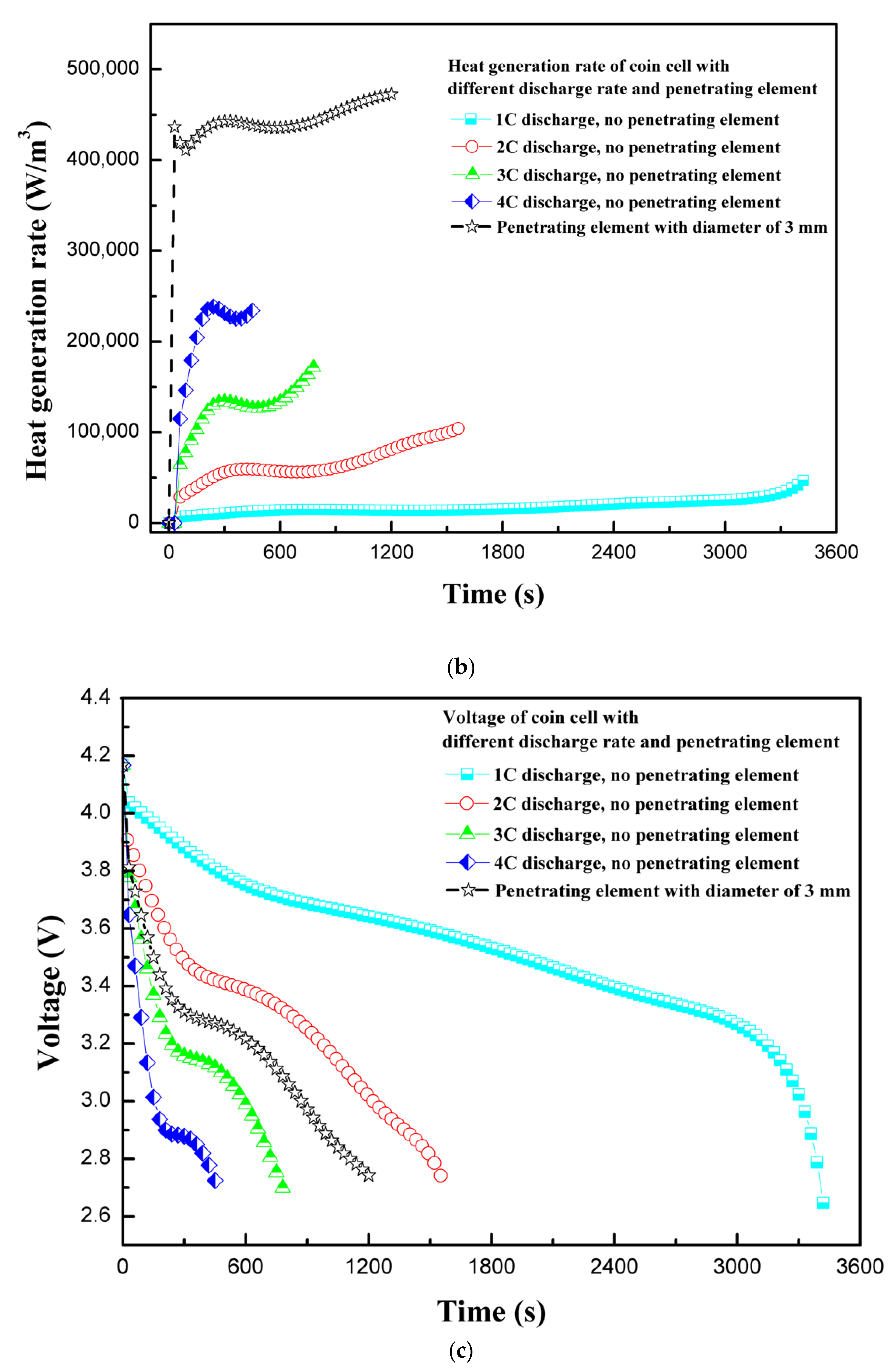
4.2. Effect of Discharge Rate

The discharge rate of 1C discharges a fully-charged 100% SOC LIB in approximately 1 h. For the safety and longevity of the battery life, the LIBs are advised to charge less than 100% and not to discharge fully to 0% SOC. In simple terms, the continuous discharge rate indicates rate of energy extraction from battery, whereby the higher the discharge rate, the higher the energy extraction rate will be. However, during high-discharge output, LIBs suffer enhanced heat generation, which must be dissipated to safely operate LIBs. Moreover, the batteries suffer performance degradation at extreme temperatures, resulting in lower performance or sometimes malfunctioning. In this section, the effect of different discharge rates during normal operation is compared to coin cell behavior with penetrating element. Figure 4a shows the temperature profiles for different discharge rates and with penetrating element. The trend is similar to the one observed by Vyroubal et al. [19]. As expected for normal discharge tests, the temperature increases as the discharge rate of the coin cell is increased. For safety reasons, the LIR2450 coin cell temperature must not exceed 60 °C during normal operation. Therefore, either the discharge rate should be maintained low, or a high heat transfer co-efficient cooling system needs to be provided. As the discharge rate increases from 1C to 4C, the maximum coin cell temperature increases by 26.2 °C, and with the penetrating element the temperature increases by 84.0 °C. The temperature of the coin cell with penetrating element increases sharply due to development of a secondary current at the short-circuit site. Interestingly, the maximum temperature is observed at the center of the coin cell in both cases—without penetrating element and with penetrating element at center.
The discharge of LIBs at different C-rates is associated with exothermic reactions. Moreover, the heat generation rate is also dependent on the material of construction of electrodes and electrolyte. In the present study, the LiCoO2 chemistry-based LIR2450 coin cell is considered. The in-depth heat generation rate during normal charging–discharging has been previously studied [28]. Figure 4b shows the heat generation rate variation with various discharge rates and penetrating element. For discharge rates of 1C and 2C, the total heat generation rate increases steadily, whereas for higher discharge rates the heat generation rate spikes slightly. During the normal operation of LIBs, the major part of heat is generated due to electrochemical reaction. Moreover, this heat generation is dependent on operating temperature, as electrochemical reactions are very sensitive to temperature. The complexity of electrochemical modeling arises as the continuous increase in temperature of the cell affects the electrochemical reaction. In addition, for the cases involving thermal abuse caused by nail penetration or crash, more complexity is added as LIB may behave abruptly, leading to fire or explosion, if thermal runaway temperature is reached. As shown in Figure 4b, in the case of penetrating element, the heat generation rate increases abruptly initially and then increases steadily. The abrupt increase in the heat generation rate is attributed to the formation of a high-current density area at the site of penetrating element, with very low resistance compared to battery internal resistance. In addition, the small sub-peaks for heat generation observed during the discharge process are related to the phase change influence of electrodes [28].
Figure 4c shows the voltage response of a coin cell when different discharge rates are employed and compared with voltage response, with penetrating element of diameter 3 mm at 1C discharge rate. For the normal operation of the coin cell, the voltage response shows a general trend. With penetrating element, a discharge cut-off voltage of 2.75 V is reached at around 1200 s with 1C discharge. The rapid attainment of a discharge cut-off voltage attributes to the flow of a secondary high-density current due to an internal short circuit at the site of penetrating element. The results of maximum temperature, heat generation rate, and voltage profiles of the coin cell at different discharge rates and with penetrating element show that the discharge rate as well as penetration have a substantial effect on the thermal behavior of the coin cell.

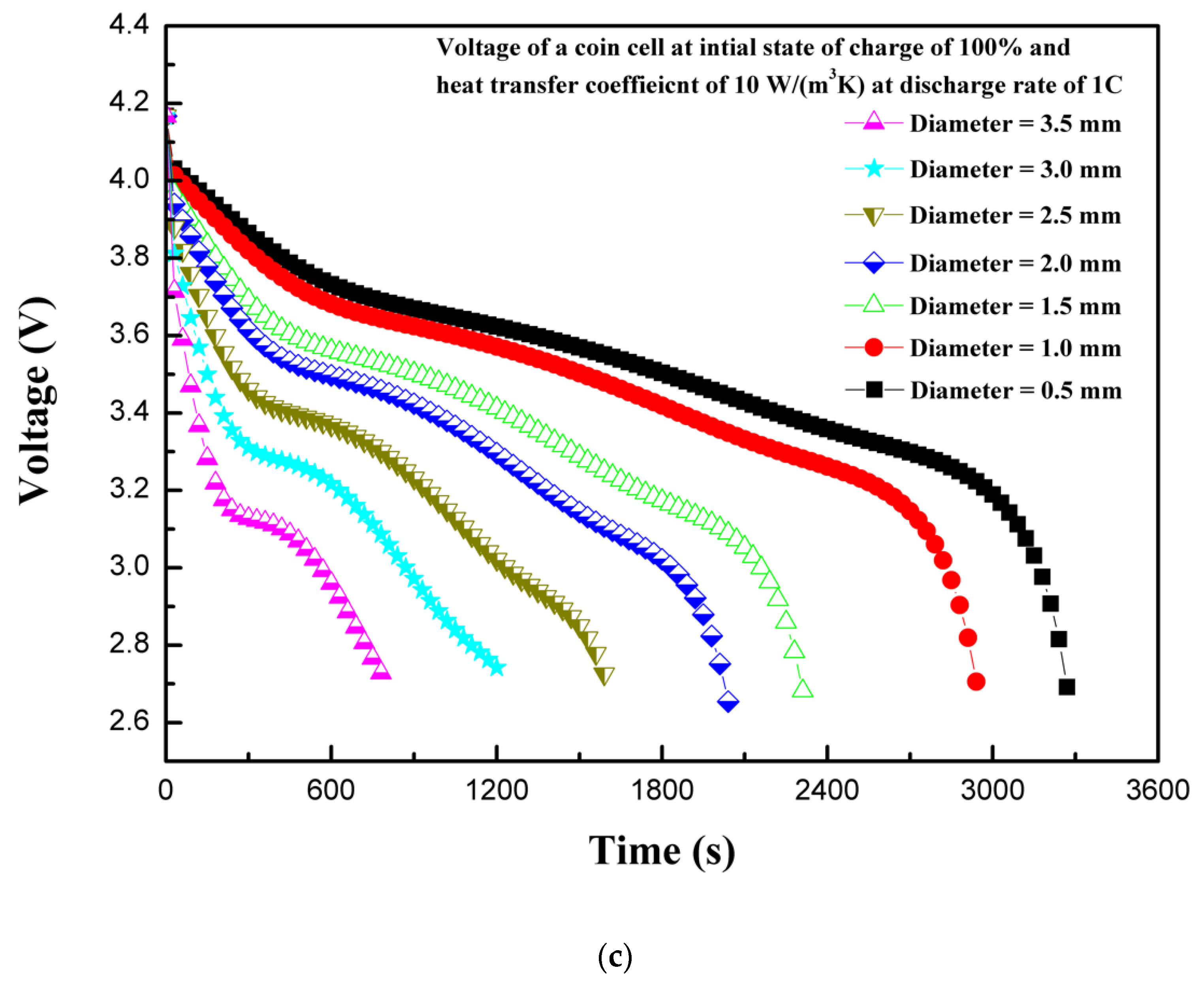
4.3. Effect of Penetarting Element Size

In LIBs, the electrodes are separated by a thin separator. The separator prevents the direct contact of electrodes. The electrodes and electrolytes are tightly packed, as in the case of the LIR2450 coin cell, by positive and negative caps. The generally-used polymer separator has safety issues when combined with high-density and high-capacity LIBs, because, during internal short circuit by penetration or crash, the separator shrinks in volume due to heat, making the direct contact of electrodes possible, which is a dangerous scenario [29]. The effect of different shapes of penetrating element on thermal behavior have been studied previously with ellipsoid, flat, cone, and sphere shapes [6]. In the current study, a cylindrical penetrating element in the battery active material (electrodes and electrolytes) with different sizes were considered. The penetrating element with diameters of 0.5, 1.0, 1.5, 2.0, 2.5, 3.0, and 3.5 mm were considered. During the operation of battery with penetrating element, the electrodes come into contact due to deformation and, subsequently, joule heat is produced at a very high rate. The heat is transferred from the point of penetration to the whole battery by conduction, and then to the outside by convection and radiation. In some cases, the high temperature activates the chemical reactions leading to exothermic behavior, and the cell components, including electrolyte and electrode, explode either from penetrating location or safety valve with flames [5]. The nail penetration tests are characterized by a localized hotspot and the propagation of heat to the whole battery through conduction [30]. Figure 5a shows the effect of the penetrating element size on the maximum coin cell temperature. It is evident from Figure 5a that a large penetrating element produces higher temperatures, and temperature continues increasing as the penetrating element size increases. The maximum temperature of the coin cell increases by 103 °C as the penetrating element diameter was increases from 0.5 to 3.5 mm. This thermal behavior, of a large increase in temperature for higher penetrating element size, is associated with a large short-circuit area occurring during internal short circuit, leading to a large cross-sectional area available for the flow of secondary current that developed due to the short circuit (i.e., the short-circuit current is proportional to the square of the penetrating element radius) [6]. In addition, a large penetrating element leads to a considerable reaction force and a high-buckling displacement [6]. The thermal behavior due to accumulated heat with penetrating element is closely related to battery internal resistance and contact resistance, which is a direct function of penetrating element size (i.e., diameter) [31].
The heat generation rate increases rapidly at the start due to the internal short circuit for all the cases of different diameters of penetrating element. The total heat generation rate is comprised of heat due to ohmic source, heat due to electrochemical reaction source, and heat due to short-circuit source. As the diameter of the penetrating element decreases, the heat due to the short circuit decreases, as shown in Figure 5b. As the diameter of the penetrating element increases, the contribution of heat due to the short circuit increases. The maximum total volumetric heat generation rate of 636,744.6 W/m3 is recorded for the penetrating element with diameter of 3.5 mm, whereas the maximum total heat generation rate of 57,784.6 W/m3 is recorded for diameter of 0.5 mm. Figure 5c shows the voltage response of a coin cell with different penetrating element sizes. It is seen from Figure 5c that as the penetrating diameter increases, from 0.5 to 3.5 mm, the time to attain the discharge cutoff voltage of 2.75 V reduces. The coin cell with the penetrating element of 0.5 mm diameter attained a discharge cut-off voltage of 2.75 V in 3270 s, whereas, for the penetrating element diameter of 3.5 mm only 780 s was needed. The results of maximum temperature, heat generation rate, and voltage profiles of the coin cell for different penetrating element diameters show that penetrating element size has a substantial effect on the thermal behavior of a coin cell.

4.4. Effect of Initial State of Charge

The state of charge is an indicator of usable energy available compared to maximum rated usable energy. Figure 6a shows the effect of initial state of charge (SOC) on the maximum temperature of the coin cell. The maximum temperature of the coin cell increased with the increase in the initial SOC of the coin cell. Although temperature increased continuously for all SOC levels, the cases with high initial SOC levels showed high temperatures owing to stable high currents for sufficiently long periods [6]. Moreover, the rate of increase of temperature is slightly higher for low SOC level, because the available energy depleted quickly in the case of low SOC levels. The maximum and minimum temperatures of 113.5 and 67.7 °C are observed for 100% and 40% SOC levels, respectively. Similarly, the continuous heat generation rate is maintained for long periods with higher SOCs leading to higher temperatures, as shown in Figure 6b. The characteristic rapid rise of the heat generation rate at the start is observed for all cases of SOCs. The maximum and minimum total heat generation rates of 472,707.2 and 340,656.4 W/m3 are observed for 100% and 40% SOC levels, respectively. The results of various SOCs show that the thermal runaway temperature attainment is strongly dependent on the SOC level. The results support the findings of Cai et al., which showed that chances of partially-charged LIBs (at 50% SOC or lower) to attain thermal runaway temperatures are rare during mechanical abuse [32]. The maximum temperature decreases as the SOC decreases. On the other hand, more energy is produced for higher SOC levels, as visible for the area below the heat generation curve shown in Figure 6a [31]. The thermal stability of LIB components is strongly dependent on SOC levels [33]. LIBs operate based on the intercalation–deintercalation phenomenon, in which lithium-ion occupies porous structures of cathodes or anodes during charging–discharging. As the level of lithiation in negative electrodes increases, more lithium-ions are available for reactions that are exothermic in nature [34]. The exothermic reactions involving cathodes and electrolytes increase heat generation linearly with the increase in the SOC level, which indicates that SOC levels can play an important role in the event of thermal runaway. This is experimentally shown by Mao et al., where batteries with 100% SOC were burnt owing to thermal runaway, and low SOC level batteries with 0% and 50% were not burnt [22].
Besides this, other parameters, including battery type, battery design, components of active battery material, battery shape, and size of battery, are key important factors that can affect the thermal behavior of LIBs. Therefore, the SOC level effect with penetrating element on the thermal behavior of LIBs is very specific, and may have different results (with above suggested parameters) for different batteries. In addition, the temperature non-uniformity is dependent on the size of the battery under consideration. In the present study, due to the compact size of the coin cell, the temperature non-uniformity study is not considerably relevant. The initial rise of the heat generation rate is maximum for 100% SOC and decreases as the SOC level decreases. Zao et al. discussed practical ways to prevent thermal runaway, and ruled out the decrease of SOC as a practical option to prevent thermal runaway in the case of nail penetration [31]. However, this strategy can be used for aircraft “cargo-only” transportation of batteries, where SOC should be kept at less than 30% to prevent thermal runaway [35]. Figure 6c shows the voltage response of the coin cell for different SOC levels. For different SOC levels, the initial voltage is different [9]. For low SOC, the capacity depletes soon after the stable current is established, with the attainment of a discharge cut-off voltage of 2.75 V. This results in a relatively less heat generation rate, leading to a comparatively low temperature. The voltage curve trends are the same for all the cases of SOC, as all other parameters are kept constant except SOC. The present model did not consider the discussions on thermal runaway behavior for temperatures exceeding 128 °C, as thermal runaway behavior including material decomposition is not included in the present study [6,36]. The results of maximum temperature, heat generation rate, and voltage profile of the coin cell for different SOC levels show that the initial SOC level has a substantial effect on the thermal behavior of the coin cell.

4.5. Effect of the Location of the Penetrating Element

The location of the penetrating element can have different effects on different types of batteries. In case of accidents, it is unpredictable as to how and where the battery will be impacted in terms of penetration or crash. As the battery design is different for cylindrical, pouch, or coin cells with different capacities, the penetration or crash during any accident will have varying effects. In the present study, three different locations of the coin cell with penetrating element were considered. These three locations were: Center of the coin cell, middle of the radius, and edge of the coin cell. Figure 7a shows the effect of penetrating element location on the temperature profile of the coin cell. As evident, the temperature increases continuously regardless of penetrating element position. The penetrating element at the center of the coin cell showes slightly higher temperatures than on the middle of the radius and on edge of the coin cell. The results indicate that the penetrating location at the center of the coin cell is the most dangerous, because, with abrupt high heat generation, heat is accumulated at the nail penetration location due to the inability to dissipate heat quickly be means of conduction, convection, or radiation. The location of penetrating element can have varying effects on different types of commercially available LIBs. For example, for the 18650-type cylindrical cell, the penetrating position at the center of the cylinder along the height is the most dangerous case, as thermal runaway can spread to the entire cell. The penetrating element at other locations, than center, may not cover thermal runaway over the entire cell [22]. However, this is dependent on the size, shape, and design of the LIB. For the pouch-type LIB, which has a generally high ampere-hour capacity, the penetrating element at the center of the pouch cell on the flat side is very dangerous as a large amount of heat is accumulated. Additionally, if the penetrating element is near the tabs, that could lead to a large wraparound current source [16]. As in case of the coin cell, due to smaller size and capacity, the position of the penetrating element does not have much differentiating effect, indicating the batteries are prone to thermal runaway or fire hazards, irrespective of the location of the penetrating element. The maximum temperatures of 113.5, 108.7, and 107.5 °C are observed at the center of the coin cell, middle of the radius, and on edge of the coin cell, respectively. Figure 7b shows the voltage response of a coin cell with different penetrating element locations. The penetrating effect has minimal effect on voltage profile. The discharge cut-off voltage for all three cases reached 2.75 V at almost the same time of battery operation.
Figure 8 presents the magnitude of current density and temperature of the coin cell on the middle of the height plane and details of three different cases are presented. The vectors of current density at the central plane of the coin cell for three different cases are presented in Figure 8a,c,e. The maximum current density reaches as high as 8200 A/m2, which is an extremely high level of current concentrated at the site of penetrating element for a coin cell. The high level of flow of current occurs owing to the low resistance of the penetrating element. The arrow indicates the direction and the color indicates the magnitude of the current density vector at the central plane of the coin cell. The magnitude of the current density decreases with the distance from the penetrating element. Evidently, the temperature also decreases with the distance from the penetrating element. From Figure 8b, it can be seen that the lowest temperature is observed at the edges and this can be attributed to the availability of heat dissipation surface near the edges. The temperature contours for three different cases are presented in Figure 8b,d,f. In addition, the difference between maximum and minimum temperatures for all three cases with penetrating element are below 3.5 °C, owing to the compact size of the coin cell and heat spreading to the entire coin cell. Radial symmetry is observed, as shown in Figure 8a,b, for current density pattern and temperature distribution pattern, owing to the uniform temperature gradient between the center of the coin cell and the edge of the coin cell. The highest temperature is observed at the center due to the penetrating element, and the lowest temperature is observed at the edges with uniform convective heat transfer. The results of the maximum temperature profile, voltage profile, and current density profile for the coin cell with different penetrating locations show minimal variation considering the thermal behavior of the coin cell.

4.6. Effect of the Heat Transfer Coefficient

Figure 9 shows the effect of the heat transfer co-efficient on the maximum temperature of the coin cell during the internal short circuit. As expected, the heat transfer co-efficient has a consequential effect on the maximum temperature of the coin cell. A cooling convective heat transfer coefficient of 1 W/(m2K) or less represents a condition similar to a battery packed with insulating materials, whereas 200 W/(m2K) or more indicates an effective liquid cooling situation [31]. For the case of the coin cell, the heat transfer coefficients ranging from 5 to 25 W/(m2K) are considered, which are reasonable assumptions for partially-insulated to forced air cooling convection. The heat transfer coefficient of 10 W/(m2K) can be considered as a natural convection case. The heat dissipation term presented in Equation (7) is dependent on temperature variations of LIBs. The maximum temperature of 165.3 °C is observed in the case of a heat transfer coefficient of 5 W/(m2K), whereas the lowest temperature of 59.5 °C is observed for a heat transfer coefficient of 25 W/(m2K). The thickness of the battery plays an important role in transferring heat to the surface. For thicker batteries, the heat transfer coefficient is insignificant [31]; however, for thinner batteries, such as LIR2450 coin cells, the heat transfer coefficient has a substantial effect on the maximum temperature of the coin cell. Providing efficient cooling is useful, especially for cases of thermal abuse, as this is an effective tool to prevent thermal runaway or to reduce the effect of propagation of thermal runaway in LIBs, as previously discussed [23]. The results show that the heat transfer coefficient has a substantial effect on the thermal behavior of coin cells.

4.7. Effect of Short-Circuit Resistance

Figure 10 shows the variation of dimensionless short-circuit heat generation rates with dimensionless internal short-circuit resistance. The dimensionless short-circuit heat generation rate is represented by Equation (14) and the dimensionless internal short resistance is represented by Equation (15). The internal resistance of the coin cell is 400 mΩ. During the internal short circuit, heat is generated due to a short circuit along with heat generation due to electrochemical reaction source and ohmic source. The total heat generation is the sum of the electrochemical heat source, ohmic heat source, and short-circuit heat source. The results from Figure 10 indicate that there is an optimum point at which the heat generation contribution from the short circuit is maximum. A similar trend was presented with the 1 Ah capacity pouch cell by Fang et al., although the values differ as the battery under consideration is different from previously studied [21]. There are few researches which focus on the increase in charge transfer resistance by using thermal runaway retardant (TRR) such as dibenzylamine [18], by using flexible separators, or by using high-viscosity protection films [31]. With decrease of internal resistance, the contribution of heat source from the short circuit increased due to a higher short-circuit current with constant contact resistance (constant size of penetrating element) [31].
Dimensionless   short   circuit   heat   generation   rate   =   q s h o r t q E C h + q O h m i c + q s h o r t
Dimensionless   short   circuit   resistance   =   R s h o r t R c e l l
The short-circuit resistance during the penetration can play an important role, as it can affect the extent of damage to the coin cell in the case of thermal abuse leading to thermal runaway. The short-circuit resistance varies from 0.001 to 0.0000005 Ω and effects on the thermal behavior of coin cell is reported. A high value of short-circuit resistance can contain thermal runaway, whereas a very low-resistance value could facilitate the exothermic reactions leading to thermal runaway. Figure 11a shows the effect of various short-circuit resistances on the maximum coin cell temperature. It is evident from Figure 11a that a lower short-circuit resistance produces a high temperature, and the temperature continues increasing as the short-circuit resistance decreases. The maximum temperature of the coin cell increases to 82.9 °C as the short-circuit resistance decreases from 0.001 to 0.0000005 Ω. This thermal behavior of a large increase in temperature for lower short-circuit resistance is associated with the large flow of a short-circuit current with a low-resistance path. The variation in heat generation rates is considerably large for different short-circuit resistances, as shown in Figure 11b. The low heat generation for higher short-circuit resistance is reported, as the contribution from the short-circuit heat source is very low. In such cases, the electrochemical heat source is a dominating heat source. However, as the short-circuit resistance decreases, the short-circuit heat source dominates over the electrochemical heat source. This is also supported from the results of Figure 10, which shows that the contribution from the short-circuit heat source to the total heat source is relatively large for low short-circuit resistances. Figure 11c shows the voltage response of a coin cell with penetrating element diameter of 3 mm and different short-circuit resistances. It is seen from the Figure 11c that as the short-circuit resistance decreases, the time to attain the discharge cutoff voltage of 2.75 V reduces. The coin cell with a short-circuit resistance of 0.001 Ω attained a discharge cut-off voltage of 2.75 V in 3420 s, whereas the coin cell with a short-circuit resistance of 0.0000005 Ω only needed 1200 s. The results of maximum temperature, heat generation rate, and voltage profiles of the coin cell for different short-circuit resistances show that short-circuit resistance has a substantial effect on the thermal behavior of the coin cell. In addition, the findings from the present studies are useful, especially focusing on the thermal-runaway retardant (TRR) of lithium-ion batteries, as heat generation, temperature distribution, and effect of resistance could be used to evaluate the effect of TRR.

5. Conclusions

This study presents the thermal behavior of the LIR2450 micro coin cell battery, with capacity of 120 mAh, with internal short circuit by penetrating element. The numerical model is developed using voltage, temperature, and current characteristics from experimental study and validated within ±5.0%. The effect of the penetrating element size, the location of the penetrating element, initial state of charge, discharge rate, short-circuit resistance, and heat transfer coefficient on the maximum temperature and the heat generation rate of the coin cell are investigated. The maximum temperature and heat generation rate increased with the increase of the penetrating element size and initial state of charge, whereas it decreased with the increase of the heat transfer coefficient. The penetrating element at the center of the coin cell reached the highest temperature and heat generation rate, as compared to the penetrating element at middle of the radius or on the edge of the coin cell. The variation of dimensionless short-circuit heat generation rates with dimensionless short-circuit resistances showed an optimum point. The study provides comprehensive insights on the thermal behavior of lithium-ion cells during thermal abuse condition, with internal short circuit by penetrating element, and can be used for enhancing the design of safe lithium-ion batteries.

Author Contributions

Conceptualization, M.-Y.L. and M.S.P.; methodology, M.-Y.L.; software, M.S.P.; validation, M.-Y.L., M.S.P. and N.K.; experimental study, M.-Y.L., M.S.P. and J.-H.S.; numerical investigation, M.-Y.L. and M.S.P.; resources, M.-Y.L.; data reduction, M.-Y.L., M.S.P. and J.-H.S.; writing—original draft preparation, M.-Y.L. and M.S.P.; writing—review and editing, M.-Y.L., M.S.P., J.-H.S. and N.K.; visualization, M.S.P.; supervision, M.-Y.L.; project administration, M.-Y.L.; funding acquisition, M.-Y.L. All authors have read and agreed to the published version of the manuscript.

Funding

This research received no external funding.

Acknowledgments

This work was supported by LG Yonam Foundation (of Korea).

Conflicts of Interest

The authors declare no conflict of interest.

References

  1. Zubi, G.; López, R.D.; Carvalho, M.; Pasaoglu, G. The lithium-ion battery: State of the art and future perspectives. Renew. Sustain. Energy Rev. 2018, 89, 292–308. [Google Scholar] [CrossRef]
  2. Wang, Y.; Liu, B.; Li, Q.; Cartmell, S.; Ferrara, S.; Deng, Z.D.; Xiao, J. Lithium and lithium ion batteries for applications in microelectronic devices: A review. J. Power Sources 2015, 286, 330–345. [Google Scholar] [CrossRef] [Green Version]
  3. Patil, M.S.; Panchal, S.; Kim, N.; Lee, M.-Y. Cooling Performance Characteristics of 20 Ah Lithium-Ion Pouch Cell with Cold Plates along Both Surfaces. Energies 2018, 11, 2550. [Google Scholar] [CrossRef] [Green Version]
  4. Chen, Z.; Xiong, R.; Lu, J.; Li, X. Temperature rise prediction of lithium-ion battery suffering external short circuit for all-climate electric vehicles application. Appl. Energy 2018, 213, 375–383. [Google Scholar] [CrossRef]
  5. Wang, Q.; Mao, B.; Stoliarov, S.I.; Sun, J. A review of lithium ion battery failure mechanisms and fire prevention strategies. Prog. Energy Combust. Sci. 2019, 73, 95–131. [Google Scholar] [CrossRef]
  6. Liu, B.; Yin, S.; Xu, J. Integrated computation model of lithium-ion battery subject to nail penetration. Appl. Energy 2016, 183, 278–289. [Google Scholar] [CrossRef] [Green Version]
  7. Liao, Z.; Zhang, S.; Li, K.; Zhao, M.; Qiu, Z.; Han, D.; Zhang, G.; Habetler, T.G. Hazard analysis of thermally abused lithium-ion batteries at different state of charges. J. Energy Storage 2020, 27, 101065. [Google Scholar] [CrossRef]
  8. Chen, M.; Liu, J.; He, Y.; Yuen, R.; Wang, J. Study of the fire hazards of lithium-ion batteries at different pressures. Appl. Therm. Eng. 2017, 125, 1061–1074. [Google Scholar] [CrossRef]
  9. Liu, B.; Jia, Y.; Yuan, C.; Wang, L.; Gao, X.; Yin, S.; Xu, J. Safety issues and mechanisms of lithium-ion battery cell upon mechanical abusive loading: A review. Energy Storage Mater. 2020, 24, 85–112. [Google Scholar] [CrossRef]
  10. Wang, Q.; Ping, P.; Zhao, X.; Chu, G.; Sun, J.; Chen, C. Thermal runaway caused fire and explosion of lithium ion battery. J. Power Sources 2012, 208, 210–224. [Google Scholar] [CrossRef]
  11. Williard, N.; He, W.; Hendricks, C.; Pecht, M. Lessons Learned from the 787 Dreamliner Issue on Lithium-Ion Battery Reliability. Energies 2013, 6, 4682–4695. [Google Scholar] [CrossRef] [Green Version]
  12. Qin, T.; Zeng, S.; Guo, J.; Skaf, Z. State of Health Estimation of Li-ion Batteries with Regeneration Phenomena: A Similar Rest Time-Based Prognostic Framework. Symmetry 2017, 9, 4. [Google Scholar] [CrossRef] [Green Version]
  13. Feng, X.; Sun, J.; Ouyang, M.; Wang, F.; He, X.; Lu, L.; Peng, H. Characterization of penetration induced thermal runaway propagation process within a large format lithium ion battery module. J. Power Sources 2015, 275, 261–273. [Google Scholar] [CrossRef]
  14. Ping, P.; Wang, Q.; Huang, P.; Sun, J.; Chen, C. Thermal behaviour analysis of lithium-ion battery at elevated temperature using deconvolution method. Appl. Energy 2014, 129, 261–273. [Google Scholar] [CrossRef]
  15. Xia, Y.; Chen, G.; Zhou, Q.; Shi, X.; Shi, F. Failure behaviours of 100% SOC lithium-ion battery modules under different impact loading conditions. Eng. Fail. Anal. 2017, 82, 149–160. [Google Scholar] [CrossRef]
  16. Yamanaka, T.; Takagishi, Y.; Tozuka, Y.; Yamaue, T. Modeling lithium ion battery nail penetration tests and quantitative evaluation of the degree of combustion risk. J. Power Sources 2019, 416, 132–140. [Google Scholar] [CrossRef]
  17. Chen, M.; Bai, F.; Song, W.; Lv, J.; Lin, S.; Feng, Z.; Li, Y.; Ding, Y. A multilayer electro-thermal model of pouch battery during normal discharge and internal short circuit process. Appl. Therm. Eng. 2017, 120, 506–516. [Google Scholar] [CrossRef] [Green Version]
  18. Shi, Y.; Noelle, D.J.; Wang, M.; Le, A.V.; Yoon, H.; Zhang, M.; Meng, Y.S.; Qiao, Y. Exothermic behaviors of mechanically abused lithium-ion batteries with dibenzylamine. J. Power Sources 2016, 326, 514–521. [Google Scholar] [CrossRef] [Green Version]
  19. Vyroubal, P.; Kazda, T. Finite element model of nail penetration into lithium ion battery. J. Energy Storage 2018, 20, 451–458. [Google Scholar] [CrossRef]
  20. Noelle, D.J. Investigating Internal Short Circuit Heating to Inform Novel Lithium-Ion Battery Safety Strategies. Ph.D. Thesis, University of California, San Diego, CA, USA, 2018. [Google Scholar]
  21. Fang, W.; Ramadass, P.; Zhang, Z. Study of internal short in a Li-ion cell-II. Numerical investigation using a 3D electrochemical-thermal model. J. Power Sources 2014, 248, 1090–1098. [Google Scholar] [CrossRef]
  22. Mao, B.; Chen, H.; Cui, Z.; Wu, T.; Wang, Q. Failure mechanism of the lithium ion battery during nail penetration. Int. J. Heat Mass Transf. 2018, 122, 1103–1115. [Google Scholar] [CrossRef]
  23. Zhao, R.; Liu, J.; Gu, J. Simulation and experimental study on lithium ion battery short circuit. Appl. Energy 2016, 173, 29–39. [Google Scholar] [CrossRef]
  24. Wang, M.; Le, A.V.; Noelle, D.J.; Shi, Y.; Meng, Y.S.; Qiao, Y. Internal-short-mitigating current collector for lithium-ion battery. J. Power Sources 2017, 349, 84–93. [Google Scholar] [CrossRef] [Green Version]
  25. Ansys Inc. “ANSYS Fluent theory guide 2019 release,” ANSYS, Inc., December 2019. [Online]. Available online: http://www.ansys.com (accessed on 1 December 2019).
  26. Kim, U.S.; Yi, J.; Shin, C.B.; Han, T.; Park, S. Modeling the Dependence of the Discharge Behavior of a Lithium-Ion Battery on the Environmental Temperature. J. Electrochem. Soc. 2011, 158, A611–A618. [Google Scholar]
  27. Gu, H. Mathematical Analysis of a Zn/NiOOH Cell. J. Electrochem. Soc. 1983, 130, 1459–1464. [Google Scholar] [CrossRef]
  28. Giel, H.; Henriques, D.; Bourne, G.; Markus, T. Investigation of the heat generation of a commercial 2032 (LiCoO2) coin cell with a novel differential scanning battery calorimeter. J. Power Sources 2018, 390, 116–126. [Google Scholar] [CrossRef]
  29. Kim, C.-S.; Yoo, J.-S.; Jeong, K.-M.; Kim, K.; Yi, C.-W. Investigation on internal short circuits of lithium polymer batteries with a ceramic-coated separator during nail penetration. J. Power Sources 2015, 289, 41–49. [Google Scholar] [CrossRef]
  30. Maleki, H.; Howard, J.N. Internal short circuit in Li-ion cells. J. Power Sources 2009, 191, 568–574. [Google Scholar] [CrossRef]
  31. Zhao, R.; Liu, J.; Gu, J. A comprehensive study on Li-ion battery nail penetrations and the possible solutions. Energy 2017, 123, 392–401. [Google Scholar] [CrossRef]
  32. Cai, W.; Wang, H.; Maleki, H.; Howard, J.; Curzio, E.L. Experimental simulation of internal short circuit in Li-ion and Li-ion-polymer cells. J. Power Sources 2011, 196, 7779–7783. [Google Scholar] [CrossRef]
  33. Wang, Q.; Sun, J.; Yao, X.; Chen, C. Thermal Behavior of Lithiated Graphite with Electrolyte in Lithium-Ion Batteries. J. Electrochem. Soc. 2006, 153, A329–A333. [Google Scholar] [CrossRef]
  34. Maleki, H.; Deng, G.; Haller, I.K.; Anani, A.; Howard, J.N. Thermal Stability Studies of Binder Materials in Anodes for Lithium-Ion Batteries. J. Electrochem. Soc. 2000, 147, 4470–4475. [Google Scholar] [CrossRef]
  35. IATA. 2020 Lithium Battery Guidance Document. 2020. Available online: https://www.iata.org/contentassets/05e6d8742b0047259bf3a700bc9d42b9/lithium-battery-guidance-document-2020.pdf (accessed on 1 January 2020).
  36. Chiu, K.-C.; Lin, C.-H.; Yeh, S.-F.; Lin, Y.-H.; Chen, K.-C. An electrochemical modeling of lithium-ion battery nail penetration. J. Power Sources 2014, 251, 254–263. [Google Scholar] [CrossRef]
Figure 1. Experimental setup.
Symmetry 12 00246 g001
Figure 2. Numerical model geometry and meshing.
Symmetry 12 00246 g002
Figure 3. Voltage and temperature results comparison for the experimental study and the developed numerical model.
Symmetry 12 00246 g003
Figure 4. (a) Temperature profiles for different discharge rates and with penetrating element. (b) Heat generation rate profiles for different discharge rates and with penetrating element. (c) Voltage profiles for different discharge rates and with penetrating element.
Symmetry 12 00246 g004aSymmetry 12 00246 g004b
Figure 5. (a) Temperature profiles of the coin cell for different penetrating element sizes. (b) Heat generation rate profiles of the coin cell for different penetrating element sizes. (c) Voltage profiles of the coin cell for different penetrating element sizes.
Symmetry 12 00246 g005aSymmetry 12 00246 g005b
Figure 6. (a) Temperature profiles of the coin cell for different levels of initial state of charge. (b) Heat generation rate profiles of the coin cell for different levels of initial state of charge. (c) Voltage profiles of the coin cell for different levels of initial state of charge.
Symmetry 12 00246 g006aSymmetry 12 00246 g006b
Figure 7. (a) Temperature profiles for different locations of the penetrating element. (b) Voltage profiles for different locations of the penetrating element.
Symmetry 12 00246 g007
Figure 8. Magnitude of current density (a,c,e) and temperature distribution (b,d,f) of the coin cell, with penetrating element diameter of 3 mm and heat transfer coefficient of 10 W/(m3K), at a discharge rate of 1C, with initial state of charge (SOC) of 100% at the center of the cell, middle of the radius, and edge of the coin cell.
Symmetry 12 00246 g008
Figure 9. Temperature profiles for different heat transfer co-efficients.
Symmetry 12 00246 g009
Figure 10. Dimensionless short-circuit heat generation rate variation with dimensionless internal short-circuit resistance.
Symmetry 12 00246 g010
Figure 11. (a) Temperature profiles of the coin cell for different internal short-circuit resistances. (b) Heat generation rate profiles of the coin cell for different internal short-circuit resistances. (c) Voltage profiles of the coin cell for different internal short-circuit resistances.
Symmetry 12 00246 g011aSymmetry 12 00246 g011b
Table 1. The thermal and electrical properties of the 120 mAh LIR2450 coin cell.
SpecificationsValues
Cathode materialLiCoO2
Anode materialGraphite
Nominal capacity (mAh)120
Mass (g)5
Specific heat capacity (J/kg⋅K)1000
Internal resistance (mΩ)≤400
Density (kg/m3)1940
Thermal conductivity (W/m-K)18.2
Geometry specifications
Diameter (mm)24.5
Height (mm)5
Table 2. Equipment details.
EquipmentParameterSpecifications
KIKUSUI electronic load PLU-150Operating voltage1.5 to 150 V
Current range300 mA to 30 A
Maximum power150 W
GL820 Data loggerOperating range−200  °C  ≤  TS  ≤  400  °C
Constant temperature and humidity control roomTemperature range−30 to 60  °C
Humidity range30% to 95% RH
Table 3. Experimental values for co-efficient of U and Y functions.
Co-Efficient of UValuesCo-Efficient of YValues
a04.167186b00.923942
a1−1.12224b1−7.07927
a21.522472b237.43602
a3−3.46622b3−87.1731
a45.954965b490.32512
a5−3.55203b5−34.5455

