Three-Saddle-Foci Chaotic Behavior of a Modified Jerk Circuit with Chua’s Diode


Abstract
1. Introduction
2. Formulation of a Modified Chaotic Jerk Circuit with Chua’s Diode to a System of ODEs
3. Analysis for Chaotic Behavior of the System
3.1. Case 1:
3.2. Case 2:
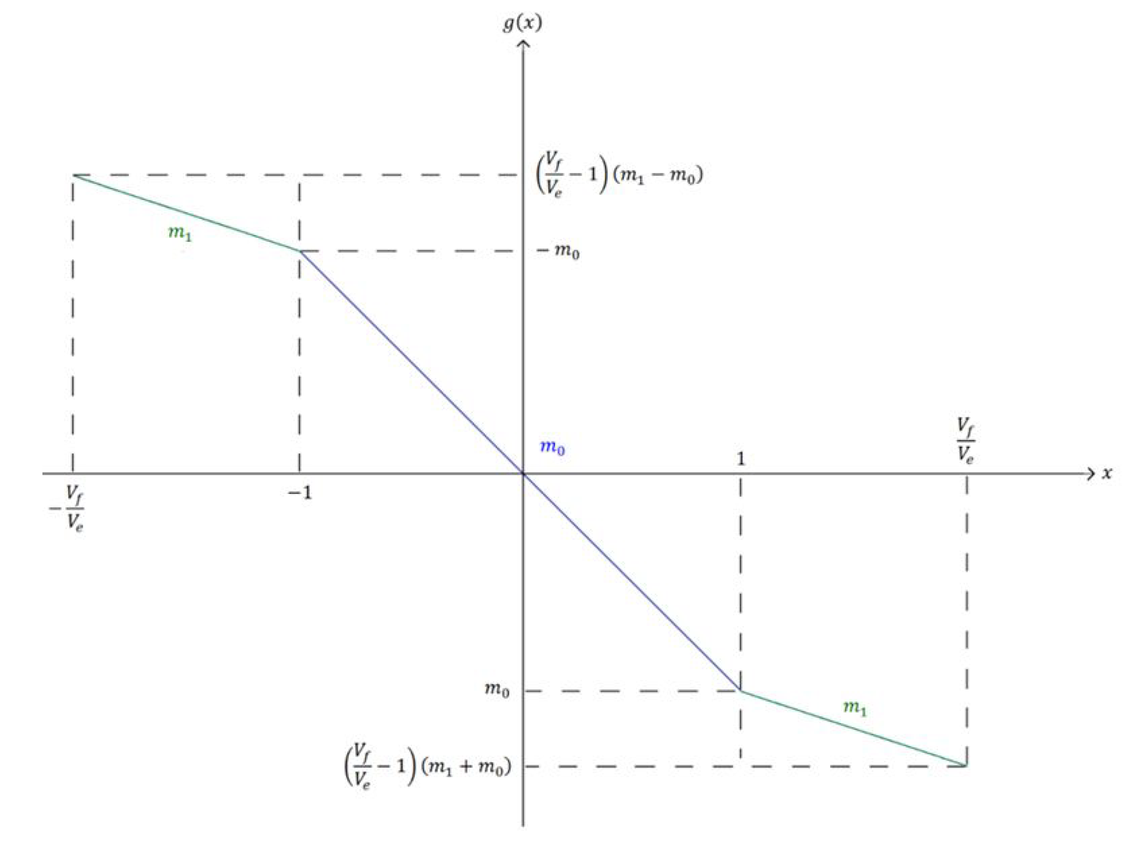
3.3. Case 3:
3.4. Type of Equilibrium Points
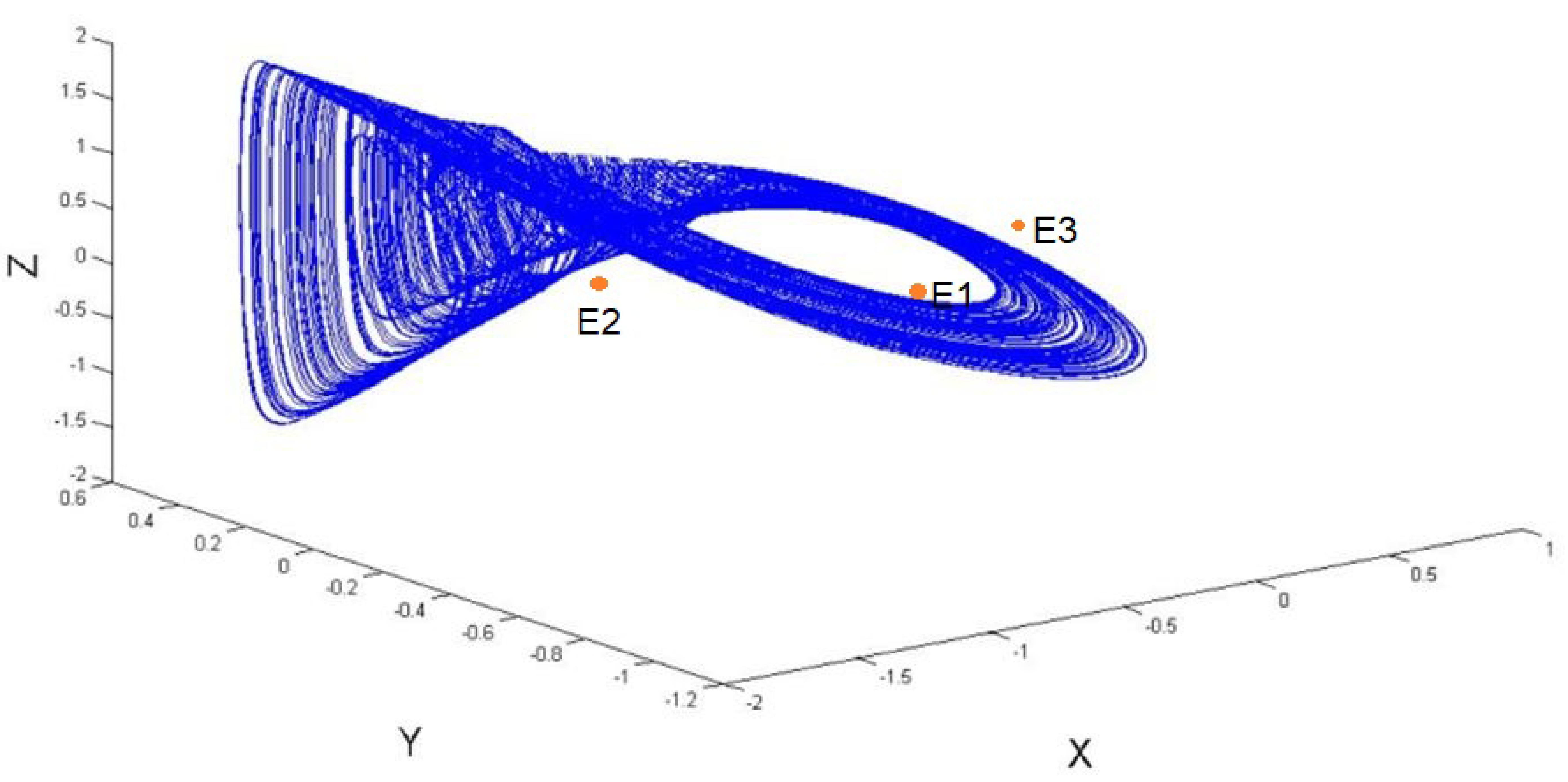
3.5. Localization of a Hidden Attractor of The System
4. Numerical Experiment
4.1. Mathematical Analysis of the System
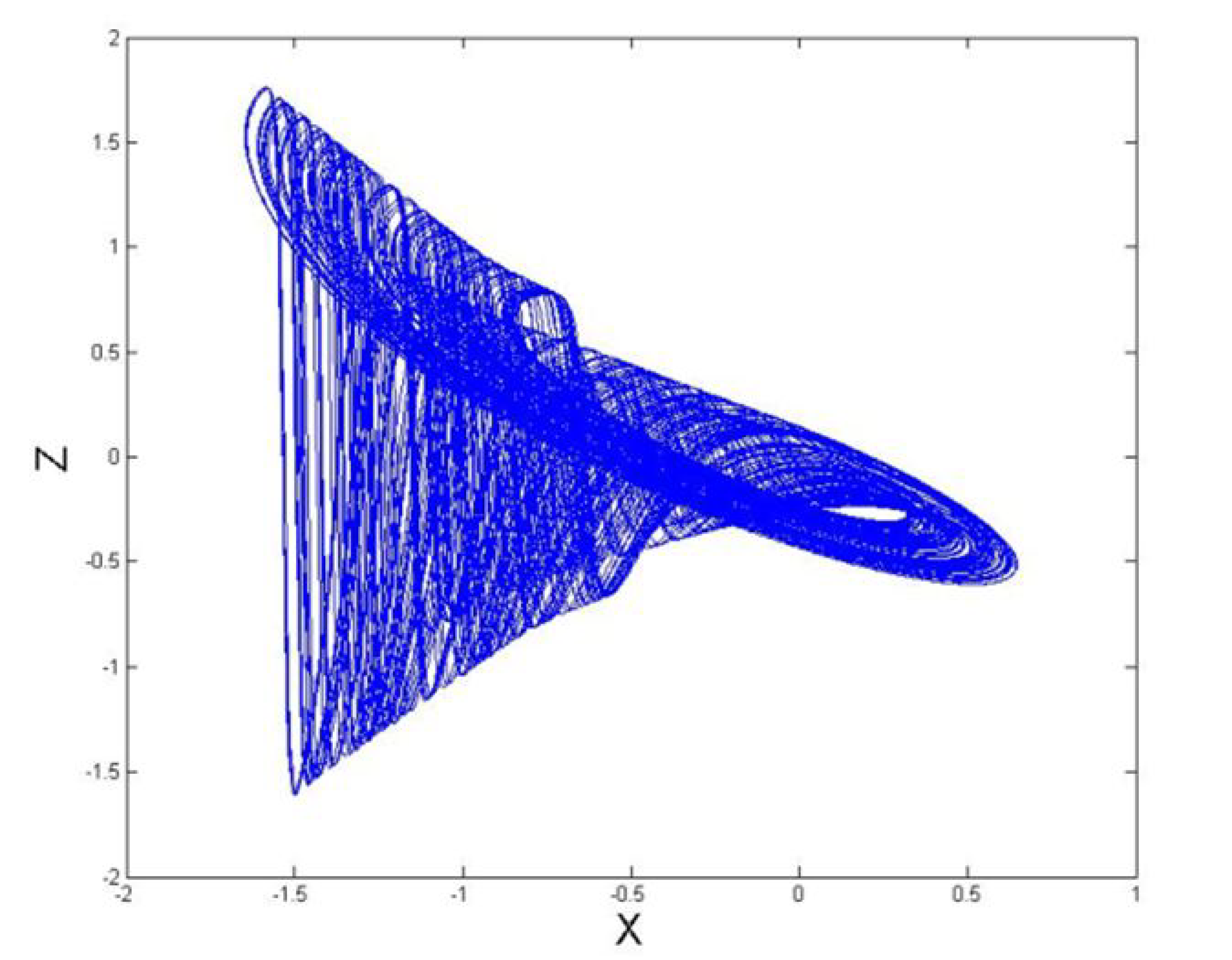
4.2. Time Waveforms and Trajectories of The System
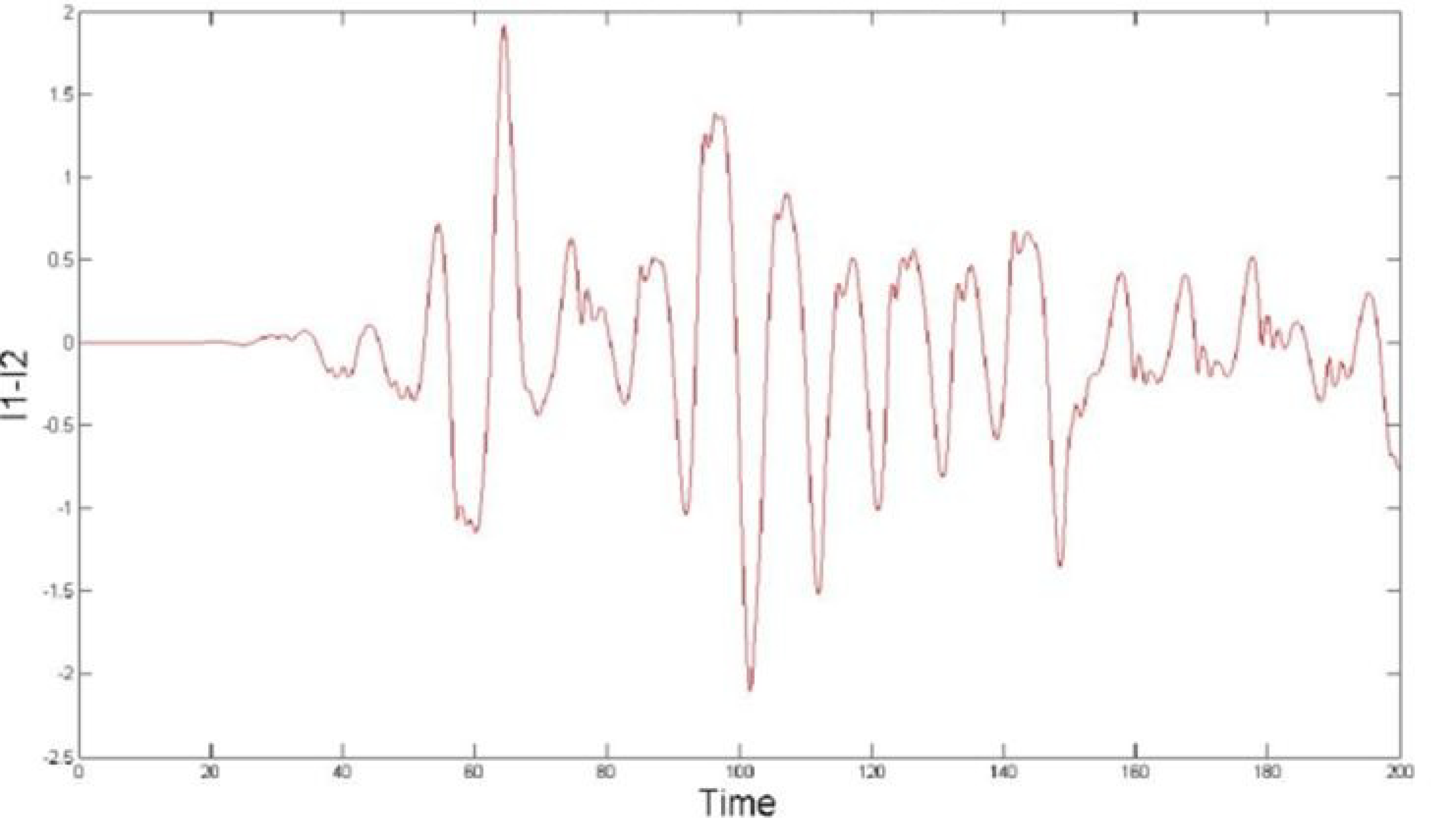
4.3. Effects of Changing Initial Points
5. Conclusions
Funding
Acknowledgments
Conflicts of Interest
References
- Sprott, J.C. Some simple chaotic jerk functions. Am. J. Phys. 1997, 65, 537–543. [Google Scholar] [CrossRef]
- Sprott, J.C. Elegant Chaos: Algebraically Simple Chaotic Flows; World Scientific: Singapore, 2010. [Google Scholar]
- Lorenz, E.N.; Emanuel, K.A. Optimal sites for supplementary weather observations: Simulation with a small model. J. Atmos. Sci. 1998, 55, 399–414. [Google Scholar] [CrossRef]
- Thomas, R. Deterministic chaos seen in terms of feedback circuits: Analysis, synthesis, ‘labyrnth chaos. Int. J. Bifurcat. Chaos Appl. Sci. Eng. 1999, 9, 1889–1905. [Google Scholar] [CrossRef]
- Chlouverakis, K.E.; Sprott, J.C. Chaotic hyperjerk systems. Chaos Solit. Frac. 2006, 28, 739–746. [Google Scholar] [CrossRef]
- Mumuangsaen, B.; Srisuchinwong, B. Elementary chaotic snap flows. Chaos Solit. Frac. 2011, 44, 995–1003. [Google Scholar] [CrossRef]
- Rössler, O.E. An equation for hyperchaos. Phys. Lett. A 1979, 71, 155–157. [Google Scholar] [CrossRef]
- Liu, Z.; Lai, Y.C.; Matias, M.A. Universal scaling of Lyapunov exponents in coupled chaotic oscillators. Phys. Rev. E 2003, 67, 1–4. [Google Scholar] [CrossRef] [PubMed]
- Cuomo, K.M.; Oppenheim, A.V. Circuit implementation of synchronized chaos with applications to communications. Phys. Rev. Lett. 1993, 71, 65–68. [Google Scholar] [CrossRef]
- Blakely, J.N.; Eskridge, M.B.; Corron, N.J. A simple Lorenz circuit and its radio frequency implementation. Chaos 2007, 17, 1–5. [Google Scholar] [CrossRef]
- Matsumoto, T.; Chua, L.O.; Komuro, M. The double scroll. IEEE Trans. Circuits Syst. 1985, 32, 797–818. [Google Scholar] [CrossRef]
- Bartissol, P.; Chua, L.O. The double hook. IEEE Trans. Circuits Syst. 1988, 35, 1512–1522. [Google Scholar] [CrossRef]
- Chua, L.O.; Lin, G.-N. Canonical realization of Chua’s circuit family. IEEE Trans. Circuits Syst. 1990, 37, 885–902. [Google Scholar] [CrossRef]
- Chua, L.O. The genesis of Chua’s circuit. Archiv. Elektron. Übertragungstechnik 1992, 46, 250–257. [Google Scholar]
- Elwakil, A.S.; Kennedy, M.P. High frequency Wien-type chaotic oscillator. Electron Lett. 1998, 34, 1161–1162. [Google Scholar] [CrossRef]
- Srisuchinwong, B.; Treetanakorn, R. Current-tunable chaotic jerk circuit based on only one unity-gain amplifier. Electron Lett. 2014, 50, 1815–1817. [Google Scholar] [CrossRef]
- Srisuchinwong, B.; Nopchinda, D. Current-tunable chaotic jerk oscillator. Electron Lett. 2013, 49, 587–589. [Google Scholar] [CrossRef]
- Sprott, J.C. Simple chaotic systems and circuits. Am. J. Phys. 2000, 68, 758–763. [Google Scholar] [CrossRef]
- Sprott, J.C. A new chaotic jerk circuit. IEEE Trans. Circuits Syst. II 2011, 58, 240–243. [Google Scholar] [CrossRef]
- Xu, M. Cryptanalysis of an image encryption algorithm based on DNA sequence operation and hyper-chaotic system. 3D Res. 2017, 8, 15–24. [Google Scholar] [CrossRef]
- Morbidelli, A. Chaotic diffusion in celestial mechanics. Regul. Chaotic Dyn. 2001, 6, 339–353. [Google Scholar] [CrossRef]
- Eduardo, L.; Ruiz, A. Chaos in discrete structured population models. SIAM J. Appl. Dyn. Syst. 2012, 11, 1200–1214. [Google Scholar]
- Sivakumar, B. Chaos theory in hydrology: Important issues and interpretations. J. Hydrol. 2000, 227, 1–20. [Google Scholar] [CrossRef]
- Bozóki, Z. Chaos theory and power spectrum analysis in computerized cardiotocography. Eur. J. Obstet. Gynecol. Reprod. Biol. 1997, 71, 163–168. [Google Scholar] [CrossRef]
- Glass, L. Dynamical Disease: The Impact of Nonlinear Dynamics and Chaos on Cardiology and Medicine. In The Impact of Chaos on Science and Society; Grebogi, C., Yorke, J.A., Eds.; United Nations University Press: Tokyo, Japan, 1997. [Google Scholar]
- Saperstain, A.M. Chaos–a model for the outbreak of war. Nature 1984, 309, 303–305. [Google Scholar] [CrossRef]
- Grossmann, S.; Mayer-Kress, G. Chaos in the international arms race. Nature 1989, 337, 702–704. [Google Scholar] [CrossRef]
- Huang, L.; Bae, Y. Analysis of chaotic behavior in a novel extended love model considering positive and negative external environment. Entropy 2018, 20, 365. [Google Scholar] [CrossRef]
- Yoon, J.H.; Bak, G.M. Youngchul Bae, Fuzzy control for chaotic confliction model. Int. J. Fuzzy Syst. 2020, 22, 1961–1971. [Google Scholar] [CrossRef]
- Morgul, O. Inductorless realization of Chua oscillator. Electron. Lett. 1995, 31, 1403–1404. [Google Scholar] [CrossRef]
- Aissi, C.; Kazakos, D. An improved realization of the Chua’s circuit using RC-op amps. In Proceedings of the WSEAS International Conference on Signal Processing, Istanbul, Turkey, 27–30 May 2008; Volume 7, pp. 115–118. [Google Scholar]
- Stouboulos, I.N.; Kyprianidis, I.M.; Papadopoulou, M.S. Complex chaotic dynamics of the double-bell attractor. WSEAS Trans. Circuits Syst. 2008, 7, 13–21. [Google Scholar]
- Kyprianidis, I.M. New chaotic dynamics in Chua’s canonical circuit. WSEAS Trans. Circuits Circuits Syst. 2006, 5, 1626–1633. [Google Scholar]
- Kyprianidis, I.M.; Fotiadou, M.E. Complex dynamics in Chua’s canonical circuit with a cubic nonlinearity. WSEAS Trans. Circuits Syst. 2006, 5, 1036–1043. [Google Scholar]
- Limphodaen, L.; Chansangiam, P. Mathematical analysis for classical Chua’s circuit with two nonlinear resistors. Songklanakarin J. Sci. Technol. 2020, 42, 678–687. [Google Scholar]
- Goode, S.W. Differential Equations and Linear Algebra; Prentice Hall: Englewood Cliffs, NJ, USA, 2000. [Google Scholar]
- Kuznetsov, N.V.; Leonov, G.A.; Vagaitsev, V.I. Analytical-numerical method for attractor localization of generalized Chua’s system. Int. Fed. Autom. Control. Proc. 2010, 4, 29–33. [Google Scholar] [CrossRef]
- Leonov, G.A.; Kuznetsov, N.V.; Vagaitsev, V. Localization of hidden Chua’s attractors. Phys. Lett. A 2011, 375, 2230–2233. [Google Scholar] [CrossRef]
- Leonov, G.A.; Kuznetsov, N.V. Hidden attractors in dynamical systems. From hidden oscillations in Hilbert-Kolmogorov, Aizerman, and Kalman problems to hidden chaotic attractors in Chua circuits. Int. Bifurc. Chaos 2013, 23. [Google Scholar] [CrossRef]


| No. | Terms of Comparison | Ref. [19] | Ref. [14] | This Paper |
|---|---|---|---|---|
| 1 | Number of equilibrium points | 1 | 3 | 3 |
| 2 | Number of eigenvalues | 3 | 9 | 9 |
| 3 | Types of trajectories | 1 saddle focus node | 1 stable focus node and 2 saddle foci | 3 saddle foci |
| 4 | Number of components | 14 | 5 | 15 |
| 5 | Positions of equilibrium points | a point | 3 symmetric points | 3 symmetric points |
| 6 | Jerk-circuit type | yes | no | yes |
| 7 | Existence of Chua’s diode | no | yes | yes |
| 8 | Existence of chaotic attractors | yes | yes | yes |
| 9 | Sensitivity to initial conditions | |||
| 10 | Nonlinear system | yes | yes | yes |
Publisher’s Note: MDPI stays neutral with regard to jurisdictional claims in published maps and institutional affiliations. |
© 2020 by the author. Licensee MDPI, Basel, Switzerland. This article is an open access article distributed under the terms and conditions of the Creative Commons Attribution (CC BY) license (http://creativecommons.org/licenses/by/4.0/).
Share and Cite
Chansangiam, P. Three-Saddle-Foci Chaotic Behavior of a Modified Jerk Circuit with Chua’s Diode. Symmetry 2020, 12, 1803. https://doi.org/10.3390/sym12111803
Chansangiam P. Three-Saddle-Foci Chaotic Behavior of a Modified Jerk Circuit with Chua’s Diode. Symmetry. 2020; 12(11):1803. https://doi.org/10.3390/sym12111803
Chicago/Turabian StyleChansangiam, Pattrawut. 2020. "Three-Saddle-Foci Chaotic Behavior of a Modified Jerk Circuit with Chua’s Diode" Symmetry 12, no. 11: 1803. https://doi.org/10.3390/sym12111803
APA StyleChansangiam, P. (2020). Three-Saddle-Foci Chaotic Behavior of a Modified Jerk Circuit with Chua’s Diode. Symmetry, 12(11), 1803. https://doi.org/10.3390/sym12111803