Article

Limit Analysis of Progressive Asymmetrical Collapse Failure of Tunnels in Inclined Rock Stratum

1
State Key Laboratory of Hydraulics and Mountain River Engineering, College of Water Resource and Hydropower, Sichuan University, Chengdu 610065, China
2
School of Civil Engineering, Southwest Jiaotong University, Chengdu 610000, China
*
Author to whom correspondence should be addressed.
Symmetry 2019, 11(7), 904; https://doi.org/10.3390/sym11070904
Submission received: 2 June 2019 / Revised: 22 June 2019 / Accepted: 9 July 2019 / Published: 11 July 2019
(This article belongs to the Special Issue Advance in Nonlinear Analysis and Optimization)

Abstract

:
Tunnels commonly pass through inclined rock stratum, but research on the collapse of the rock surrounding the tunnels in inclined rock strata is currently underdeveloped. The purpose of this study was to predict the progressive asymmetrical collapse failure of deep-buried tunnels in inclined rock strata to decrease the risk of collapse during tunnel construction. We constructed a new two-dimensional progressive asymmetrical collapse failure mechanism for deep-buried tunnels in inclined rock layers to analyze their collapse failure characteristics with the help of the nonlinear Hoek–Brown yield criterion and the limit analysis theorem. The calculation equations of the range and total weight of the asymmetrical collapsing block in rectangular and circular tunnels were obtained via theoretical derivation. The validity of the proposed method in this work was verified by comparison with existing research. To discuss the impact of different parameters on the range and total weight of an asymmetrical collapsing block of the surrounding rock in inclined rock stratum, the range and total weight of the asymmetrical collapsing block of the most common rectangular and circular tunnels under the varied parameters are provided. The results of this study can provide useful support for practical tunnel construction and design.

1. Introduction

Due to unfavorable factors such as excavation disturbances or late support, tunnels with weak surrounding rock are prone to collapse. Tunnel collapse has always been one of the most troublesome problems because its complex collapse failure mechanism has yet to be fully grasped. Therefore, research is urgently required to provide a beneficial reference for practical engineering. Many scholars have attempted to introduce various methods to analyze the stability of tunnels and predict tunnel collapse failure [1,2,3,4,5,6,7]. Lee et al. [1] conducted a series of centrifuge model tests and numerical simulations to investigate tunnel stability and arching effects in soft soils, and proposed the boundaries of the positive and negative arching zones. Mollon et al. [2] provided design charts for the case of a frictional and cohesive soil by determining the surface collapse pressure of a circular tunnel driven by a pressurized shield based on a translational three-dimensional multiblock failure mechanism. Zhang and Han [8] found that unfavorable factors such as rock weakening and large span caused a series of collapses in Longyou Cave in Zhejiang province, China through site investigations and laboratory tests, and proposed some effective measures to increase the safety of this cave, including slowing rock weathering. However, the kinematics of tunnel collapse were not considered in these studies, which does not reflect actual tunnel collapse mechanisms, and these methods are particularly difficult to use widely in practical engineering.
Despite the regular application of experimental and numerical methods in geotechnical engineering, the limit analysis theorem is often used to investigate the collapse of tunnels (e.g., traffic tunnels) due to its extraordinary advantages, including obtaining more accurate results by reducing assumptions and calculations [9,10,11,12]. Innovatively, Fraldi and Guarracino [13,14] identified a collapse mechanism of cavities and tunnels which can be used to obtain analytical results based on the upper bound theorem and the nonlinear Hoek–Brown yield criterion. Then, Huang and Yang [15] introduced pore water pressure into the virtual equation, and the influence of pore water pressure on the collapse of circular tunnels was determined by adopting a collapse mechanism similar to the research of Fraldi and Guarracino [13,14]. Li and Yang [16] considered the variable separation speed along the yield surface and introduced a simplified technique to investigate the collapse mechanism of a tunnel roof based on previous research. Yang and Huang [17] employed a new curved failure mechanism of shallow tunnels to discuss the collapsing shape of shallow circular tunnels with the consideration of supporting pressure, and proposed a critical depth expression for classifying shallow and deep tunnels. To more accurately describe the collapsing region in actual engineering, Yang and Huang [18] extended the 2D failure mechanism proposed by Fraldi [13,14] to a 3D collapse mechanism, and the 3D range of the collapsing blocks was found to be larger than that determined from the 2D failure mechanism.
In previous research, relatively satisfactory progress in solving tunnel collapse has been made, but these studies were limited to homogeneous and isotropic rock masses, resulting in larger dimensional deviations of collapsing blocks. The reasonable prediction of tunnel collapse in layered rock masses remains one of the most urgent problems to be solved in practical engineering [19]. To overcome the shortage of research on tunnel collapse in layered rock masses, Qin and Yang [19] established a new curved failure mechanism: a progressive failure mechanism with two intersecting continuous lines at the interface. Based on the limit analysis theorem and the variational approach, analytic solutions of the shape and region of collapsing blocks were acquired. Qin and Chian [20] also investigated the effects of rock weathering and a changing water table on collapsing blocks in layered rock masses. Yang and Zhou [21] employed a reliability-based analysis to examine the shape of collapsing blocks in rectangular tunnels considering seepage pressure through further research, and found that the supporting pressure had a profound impact on the reliability index. However, deep tunnels or cavities are usually built in inclined rock layers. Tunnel collapse research regarding inclined layered rock masses has been insufficient compared with tunnel collapse research in horizontal layered rock masses. The collapsing blocks in the abovementioned studies were all symmetrical, but the incline of the rock stratum results in asymmetrical collapsing blocks Therefore, it became necessary to propose a novel tunnel collapse mechanism to investigate the asymmetrical collapse failure of tunnels in inclined rock layers.
In this paper, the 2D progressive asymmetrical collapse mechanism of deep-buried tunnels in two inclined rock layers is constructed with reference to the findings of previous studies, and this failure mechanism is composed of four arbitrary curves. The explicit expressions of these curves are deduced from the variational principle and upper bound theorem. The upper bound solutions to the asymmetrical collapsing blocks of deep tunnels in inclined rock stratum are derived according to the analytical expressions. To describe the influence of diverse parameters on the range and total weight of the potential collapsing block, sensitivity analysis with rectangular and circular tunnels is described in inclined rock strata.

2. Methods

2.1. Theoretical Basis

2.1.1. Upper Bound Theorem of Limit Analysis

Chen [22] introduced the limit analysis theory in 1975, which includes upper and lower bound theorem. Then, the limit analysis theory was adopted to investigate geotechnical engineering problems because of its accuracy and convenience, especially for the upper bound theorem [9,15,16,17,18,19,20,21,23]. According to Chen, the upper bound theorem can be formulated as: the energy dissipated by the external loads being equated to the energy dissipated by any kinematically admissible velocity field to determine a rigorous upper bound on the true limit load while satisfying the velocity boundary conditions, the plastic flue rule, and compatibility. The theorem can be expressed as:
s F i v i d s + A Y i v i d A A σ i j ε ˙ i j d A ,
where Fi is a load acting on the boundary s, Yi indicates the body force, vi denotes the velocity across the discontinuity surface A, and σij and ε ˙ i j are the stress tensor and plastic stain rate in the kinematically admissible velocity field, respectively.
To enable the upper bound theorem of limit analysis to be more widely used in practical applications, the following assumptions are proposed: the geotechnical materials have perfect plasticity and follow the associated flow rule, and the potential collapsing blocks are rigid bodies with deformations too small to be neglected.

2.1.2. Nonlinear Hoek–Brown Yield Criterion

The Hoek–Brown criterion was first introduced in the late 1970s to estimate the rock mass strength for the design of underground excavation [24,25]. Since the development of this criterion, two forms of expression have been widely adopted to investigate geotechnical engineering problems—especially those for tightly interlocked hard rock masses [26]. One of the expressions has advantages when calculating the energy dissipation caused by the normal and shear stresses along with the velocity discontinuities [26]:
τ = A σ c ( σ n σ t σ c ) B { A , B ( 0 , 1 ) , σ t 0 , σ c 0 } ,
where A and B are mechanics parameters describing the rock mass that can be obtained by triaxial testing [27]; σc and σt represent the uniaxial compressive strength and the tensile strength at failure [13], respectively; and σn and τ are the normal and shear stress [26], respectively.

2.2. Progressive Asymmetrical Collapse Mechanism in Inclined Rock Stratum

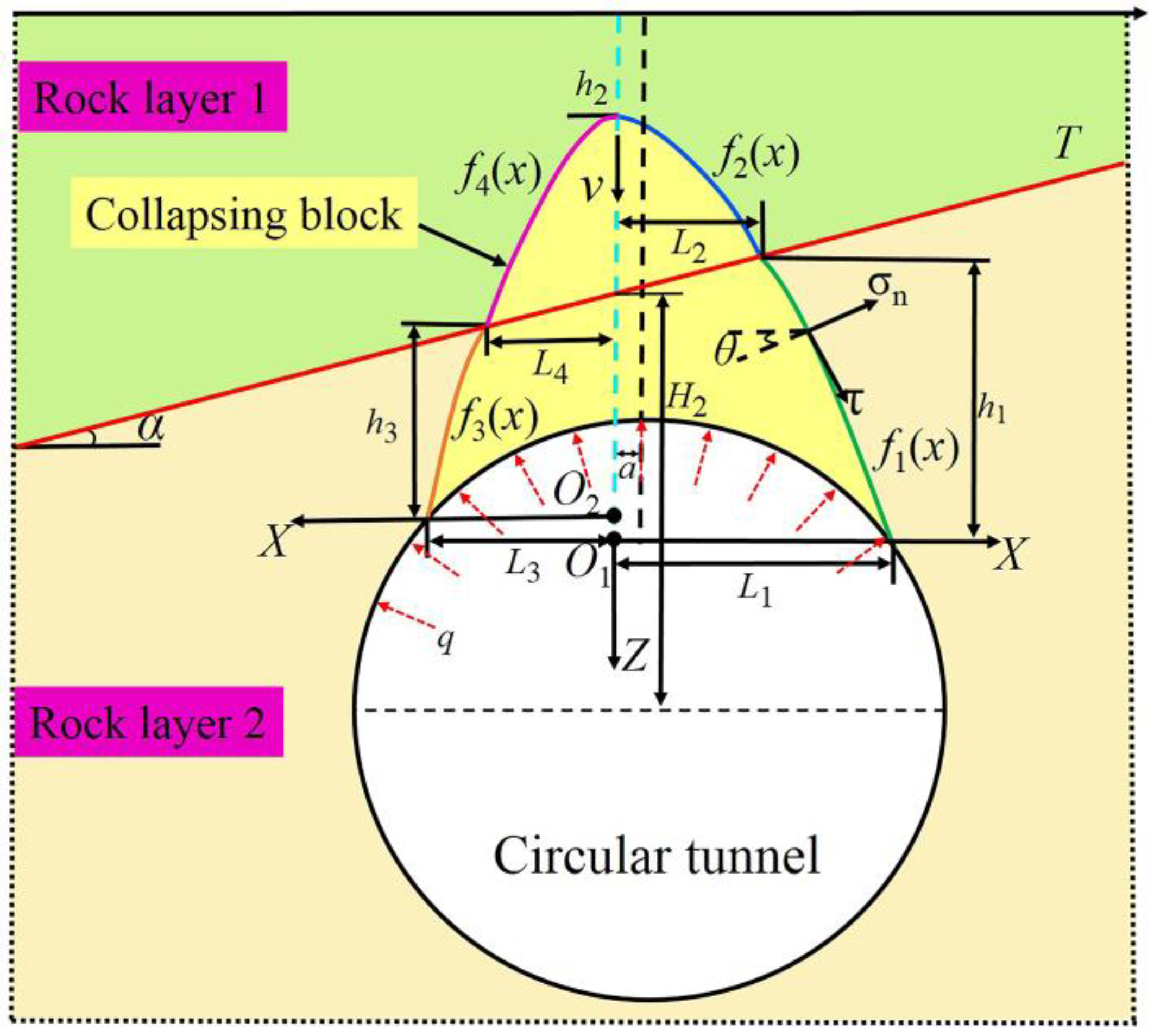
In previous studies, the upper bound theorem was often used to study the collapse mechanism of arbitrary tunnel sections owing to its convenience. In this study, we constructed a progressive asymmetrical collapse mechanism of rectangular and circular tunnels passing through two inclined rock layers, with reference to Qin et al. [19,20] and Fraldi and Guarracino [13,14], and a new collapsing block composed of four continuous sections was built to describe the most approximate mechanism in inclined rock strata. Specifically, two pairs of corresponding mechanical parameters are used to differentiate the different characteristics of the geomaterials. As shown in Figure 1 and Figure 2, the coordinate system consisting of two positive X axes is the focus, and the distance between the Z axis and the longitudinal centerline of the tunnel is a. Notably, the two positive X axes of a circular tunnel may not be on a line. Suppose the inclination angle of the inclined rock stratum is α, and the collapsing block moves vertically downward at speed v. The arbitrary curves f1(x) and f3(x) extend from the roof of rectangular or circular tunnels to the interface between the two inclined strata, respectively, and the arbitrary curves f2(x) and f4(x) are constructed from the apex of collapsing block to the intersection of the interface and the lower strata, respectively. The external rate of work and the energy dissipation along the detaching surface can be calculated based on the above collapse mechanism.

3. Upper Bound Analysis of Progressive Asymmetrical Collapsing Block

3.1. Upper Bound Analysis of Rectangular Tunnels

The energy dissipation rate and different detaching curves can be derived using the nonlinear Hoek–Brown yield criterion with reference to the research of Fraldi [13,14]. Four different sections compose the whole failure mechanism, and hence the internal forces result in the total rate of energy dissipation at the potential collapse, which can be calculated as:
P D 1 = L 2 L 1 { σ t 1 + σ c 1 [ A 1 B 1 f 1 ( x ) ] 1 1 B 1 ( 1 1 B 1 ) } v d x ,
P D 2 = 0 L 2 { σ t 2 + σ c 2 [ A 2 B 2 f 2 ( x ) ] 1 1 B 2 ( 1 1 B 2 ) } v d x
P D 3 = L 4 L 3 { σ t 1 + σ c 1 [ A 1 B 1 f 3 ( x ) ] 1 1 B 1 ( 1 1 B 1 ) } v d x
P D 4 = 0 L 4 { σ t 2 + σ c 2 [ A 2 B 2 f 4 ( x ) ] 1 1 B 2 ( 1 1 B 2 ) } v d x ,
where the detailed deduction of the total rate of energy dissipation is presented in Appendix A. L1 and L3 are the half widths of the bottom of the right and left collapsing blocks in rectangular tunnels, respectively; and L2 and L4 are the half widths of the middle of the right and left collapsing blocks intersecting with the interface between the two inclined strata, respectively; A1, B1, σc1, and σt1 are the Hoek–Brown mechanical parameters in the lower rock formation; A2, B2, σc2, and σt2 for the upper rock stratum shown in Figure 1; and f1ʹ(x), f2ʹ(x), f3ʹ(x), f4ʹ(x) are the first derivatives of the unknown continuous curves f1(x), f2(x), f3(x), and f4(x), respectively.
The work rate of the gravity of the collapsing block in rectangular tunnels can be obtained as follows:
P γ 1 = L 2 L 1 γ 1 f 1 ( x ) v d x γ 1 L 2 h 1 v + 1 2 v γ 1 L 2 2 tan α
P γ 2 = 0 L 2 γ 2 f 2 ( x ) v d x + γ 2 L 2 h 1 v 1 2 v γ 2 L 2 2 tan α
P γ 3 = L 4 L 3 γ 2 f 3 ( x ) v d x γ 1 L 4 h 3 v 1 2 v γ 1 L 4 2 tan α
P γ 4 = 0 L 4 γ 1 f 4 ( x ) v d x + γ 2 L 4 h 3 v + 1 2 v γ 2 L 4 2 tan α
where γ1 and γ2 are the rock unit weight in the lower and upper rock stratum, respectively; and h1 and h3 describe the distance from the top of rectangular tunnels to the lower curves and the interface between the two inclined strata, respectively. The supporting pressure in rectangular tunnels cannot be neglected, and the work rate generated by the supporting pressure can be calculated as follows:
P q 1 = q v L 1 cos π
P q 2 = q v L 4 cos π
where q is the supporting pressure of the rectangular tunnels. Notice that the optimal upper bound solution cannot be directly obtained by the virtual power equation. Consequently, constructing an objective function consisting of the external working rate and the total internal dissipated energy of half of the collapsing block is a prerequisite for obtaining the optimal upper solution. That is:
ς 1 [ f ( x ) , f ( x ) , x ] = P D 1 + P D 2 P γ 1 P γ 2 P q 1 = L 2 L 1 ψ 1 [ f 1 ( x ) , f 1 ( x ) , x ] v d x + 0 L 2 ψ 2 [ f 2 ( x ) , f 2 ( x ) , x ] v d x ( γ 2 γ 1 ) L 2 h 1 v 1 2 v ( γ 1 γ 2 ) L 2 2 tan α q v L 1 cos π
ς 2 [ f ( x ) , f ( x ) , x ] = P D 3 + P D 4 P γ 3 P γ 4 P q 2 = L 4 L 3 ψ 3 [ f 3 ( x ) , f 3 ( x ) , x ] v d x + 0 L 4 ψ 4 [ f 4 ( x ) , f 4 ( x ) , x ] v d x ( γ 2 γ 1 ) L 4 h 3 v + 1 2 v ( γ 1 γ 2 ) L 4 2 tan α q v L 4 cos π
where the expressions of ψ1, ψ2, ψ3, and ψ4 can be written as follows:
ψ 1 [ f 1 ( x ) , f 1 ( x ) , x ] = { σ t 1 + σ c 1 [ A 1 B 1 f 1 ( x ) ] 1 1 B 1 ( 1 1 B 1 ) } γ 1 f 1 ( x )
ψ 2 [ f 2 ( x ) , f 2 ( x ) , x ] = { σ t 2 + σ c 2 [ A 2 B 2 f 2 ( x ) ] 1 1 B 2 ( 1 1 B 2 ) } γ 2 f 2 ( x )
ψ 3 [ f 3 ( x ) , f 3 ( x ) , x ] = { σ t 1 + σ c 1 [ A 1 B 1 f 3 ( x ) ] 1 1 B 1 ( 1 1 B 1 ) } γ 1 f 3 ( x )
ψ 4 [ f 4 ( x ) , f 4 ( x ) , x ] = { σ t 2 + σ c 2 [ A 2 B 2 f 2 ( x ) ] 1 1 B 2 ( 1 1 B 2 ) } γ 2 f 4 ( x )
In Equations (13) and (14), ψ1, ψ2, ψ3, and ψ4 determine the extremes of the objective functions ς1 and ς2. Determining how to derive the upper bound solution from the objective function is important and challenging. Referring to previous studies [13,14] and based on the variational principle, four Euler equations can be obtained from by the expressions of ψ1, ψ2, ψ3, and ψ4, and the variational equations can be expressed as:
δ ψ 1 [ f 1 ( x ) , f 1 ( x ) , x ] = 0 ψ 1 f 1 ( x ) x [ ψ 1 f 1 ( x ) ] = 0
δ ψ 2 [ f 2 ( x ) , f 2 ( x ) , x ] = 0 ψ 2 f 2 ( x ) x [ ψ 2 f 2 ( x ) ] = 0
δ ψ 3 [ f 3 ( x ) , f 3 ( x ) , x ] = 0 ψ 3 f 3 ( x ) x [ ψ 3 f 3 ( x ) ] = 0
δ ψ 4 [ f 4 ( x ) , f 4 ( x ) , x ] = 0 ψ 4 f 4 ( x ) x [ ψ 4 f 4 ( x ) ] = 0
Substitute Equations (15) and (18) into Equations (19) and (22), respectively, and then employ integral calculation to derive the first derivatives of f1(x), f2(x), f3(x), and f4(x), which can be written as follows:
f 1 ( x ) = 1 B 1 A 1 1 B 1 ( γ 1 σ c 1 ) 1 B 1 B 1 ( x d 1 γ 1 ) 1 B 1 B 1
f 2 ( x ) = 1 B 2 A 2 1 B 2 ( γ 2 σ c 2 ) 1 B 2 B 2 ( x d 2 γ 2 ) 1 B 2 B 2
f 3 ( x ) = 1 B 1 A 1 1 B 1 ( γ 1 σ c 1 ) 1 B 1 B 1 ( x d 3 γ 1 ) 1 B 1 B 1
f 4 ( x ) = 1 B 2 A 2 1 B 2 ( γ 2 σ c 2 ) 1 B 2 B 2 ( x d 4 γ 2 ) 1 B 2 B 2
where d1, d2, d3, and d4 are unknown constants to be determined. As illustrated in Figure 1, the slopes of f2(x) and f4(x) are equal to 0 when the abscissa x = 0. Accordingly, the following equations and the deterministic solutions of d3 and d4 can be obtained:
f 4 ( 0 ) = f 2 ( 0 ) = 0
f 2 ( 0 ) = 0 d 2 = 0
f 4 ( 0 ) = 0 d 4 = 0
Therefore, by substituting Equations (24) and (26) into Equations (28) and (29), the following expressions of f2ʹ(x) and f4ʹ(x) are derived:
f 2 ( x ) = f 4 ( x ) = 1 B 2 A 2 1 B 2 ( γ 2 σ c 2 ) 1 B 2 B 2 x 1 B 2 B 2
We found that the slopes of f4(x) and f3(x) are equal at the intersection of the two curves f4(x) and f3(x), and the slopes of f1(x) and f2(x) are equal at the intersection of the two curves f1(x) and f2(x). Two explicit equations can be given:
f 4 ( L 4 ) = f 3 ( L 4 )
f 2 ( L 2 ) = f 1 ( L 2 )
To facilitate the calculation of the energy dissipation, two coefficients m1 and m2 are introduced to simplify the expressions:
m 1 = 1 B 1 A 1 1 B 1 ( γ 1 σ c 1 ) 1 B 1 B 1
m 2 = 1 B 2 A 2 1 B 2 ( γ 2 σ c 2 ) 1 B 2 B 2
Substituting Equations (31)–(34) into Equations (23), (25), and (30), the expressions for d1 and d3 are respectively as follows:
d 1 = γ 1 L 2 γ 1 ( m 2 m 1 L 2 1 B 2 B 2 ) B 1 1 B 1
d 3 = γ 1 L 4 γ 1 ( m 2 m 1 L 4 1 B 2 B 2 ) B 1 1 B 1
Substituting Equation (35) into (23), the expression of detaching curve f1(x) is finally given by an integral operation:
f 1 ( x ) = A 1 1 B 1 ( γ 1 σ c 1 ) 1 B 1 B 1 ( x d 1 γ 1 ) 1 B 1 + k 1
where k1 is the integration constant to be determined. Likewise, substituting Equation (30) into Equations (24) and (26), and substituting Equation (36) into (25), the expressions of f2(x), f3(x), and f4(x) are derived by integrating the equations:
f 2 ( x ) = A 2 1 B 2 ( γ 2 σ c 2 ) 1 B 2 B 2 x 1 B 2 + k 2
f 3 ( x ) = A 1 1 B 1 ( γ 1 σ c 1 ) 1 B 1 B 1 ( x d 3 γ 1 ) 1 B 1 + k 3
f 4 ( x ) = A 2 1 B 2 ( γ 2 σ c 2 ) 1 B 2 B 2 x 1 B 2 + k 4
where k2, k3, and k4 are integration constants to be determined. Since the deformation continuity should be satisfied in the intersections, the following equations can be given according to the geometrical relationship shown in Figure 1:
f 1 ( L 2 ) = f 2 ( L 2 ) = ( H 2 + L 2 tan α ) = h 1
f 3 ( L 4 ) = f 4 ( L 4 ) = ( H 2 L 4 tan α ) = h 3
f 2 ( 0 ) = h 2
H 2 = H 3 + ( b a ) tan α
a = t 0 b
where H2 represents the distance from the coordinate system origin to the intersection of the Z axis and the interface between the two strata; H1 and H3 denote the distance from the top of rectangular tunnels to the interface between the two inclined strata, respectively; h2 is the maximum height of the collapsing block; and t0 indicates the ratio of the half widths of rectangular tunnels. By introducing Equations (37)–(40) into Equations (41)–(45), respectively, the specific expressions of d1, d2, d3, and d4 can be written as:
k 1 = A 1 1 B 1 ( γ 1 σ c 1 ) 1 B 1 B 1 ( L 2 d 1 γ 1 ) 1 B 1 ( H 2 + L 2 tan α )
k 2 = A 2 1 B 2 ( γ 2 σ c 2 ) 1 B 2 B 2 L 2 1 B 2 ( H 2 + L 2 tan α ) = h 2
k 3 = A 1 1 B 1 ( γ 1 σ c 1 ) 1 B 1 B 1 ( L 4 d 3 γ 1 ) 1 B 1 ( H 2 L 4 tan α )
k 4 = A 2 1 B 2 ( γ 2 σ c 2 ) 1 B 2 B 2 L 4 1 B 2 ( H 2 L 4 tan α )
Notice that the functions f1(x) and f3(x) are equal to 0 when the abscissa x = L1 and x = L2, respectively, and the following equations are obtained:
f 1 ( L 1 ) = 0 A 1 1 B 1 ( γ 1 σ c 1 ) 1 B 1 B 1 [ ( L 1 d 1 γ 1 ) 1 B 1 ( L 2 d 1 γ 1 ) 1 B 1 ] ( H 2 + L 2 tan α ) = 0
f 3 ( L 3 ) = 0 A 1 1 B 1 ( γ 1 σ c 1 ) 1 B 1 B 1 [ ( L 3 d 3 γ 1 ) 1 B 1 ( L 4 d 3 γ 1 ) 1 B 1 ] ( H 2 L 4 tan α ) = 0
Additionally, combining Equations (23)–(26), Equations (37)–(40), and Equations (15)–(18), the expressions of ψ1, ψ2, ψ3, and ψ4 can be further formulated respectively as:
ψ 1 [ f 1 ( x ) , f 1 ( x ) , x ] = σ t 1 1 B 1 σ c 1 B 1 1 B 1 A 1 1 B 1 γ 1 1 B 1 ( x d 1 γ 1 ) 1 B 1 γ 1 k 1
ψ 2 [ f 2 ( x ) , f 2 ( x ) , x ] = σ t 2 1 B 2 σ c 2 B 2 1 B 2 A 2 1 B 2 γ 2 1 B 2 x 1 B 2 γ 2 k 2
ψ 3 [ f 3 ( x ) , f 3 ( x ) , x ] = σ t 1 1 B 1 σ c 1 B 1 1 B 1 A 1 1 B 1 γ 1 1 B 1 ( x d 3 γ 1 ) 1 B 1 γ 1 k 3
ψ 4 [ f 4 ( x ) , f 4 ( x ) , x ] = σ t 2 1 B 2 σ c 2 B 2 1 B 2 A 2 1 B 2 γ 2 1 B 2 x 1 B 2 γ 2 k 4
As a result, Equations (13) and (14) can be simplified and represented as:
ς 1 [ f ( x ) , f ( x ) , x ] = F 1 ( L 1 , L 2 ) v
ς 2 [ f ( x ) , f ( x ) , x ] = F 2 ( L 3 , L 4 ) v
where F1(L1,L2v and F2(L3,L4v are explained in Appendix B. According to the virtual power equation, in the kinematically admissible field, the external rate of work is equal to the internal energy dissipation power when the collapsing block is in the ultimate state. As such, an optimal analytical solution that satisfies the objective function can be determined. Therefore, when the objective functions are equal to 0, the geometric parameters L1, L2, L3, and L4 of the impending block can be derived individually:
F 1 ( L 1 , L 2 ) = 0
F 2 ( L 3 , L 4 ) = 0
where F1(L1,L2) = 0 and F2(L3,L4) = 0 are described in Appendix B. Then, substituting the obtained analytical solutions of L1, L2, L3, and L4 into Equations (41)–(43) can be used to determine the analytical solutions of constants h1, h2, and h3, respectively, describing the height of the progressive asymmetrical collapsing block.
The total power of the gravity of the potential collapsing block is obtained by combining Equations (7)–(10) and (37)–(40) with Equations (46)–(49), and then the total weight of the potential collapsing block in rectangular tunnels can be expressed as W1, which is given in Appendix B.

3.2. Upper Bound Analysis of Circular Tunnels

In contrast to the rectangular tunnels above, the function of the circular tunnels’ profile is more complicated. According to the geometric relationship in Figure 2, the expressions of a circular tunnel’s contour on both sides of the Z axis are given as follows:
g 1 ( x ) = R 2 ( L 1 a ) 2 R 2 ( x a ) 2
g 2 ( x ) = R 2 ( L 3 + a ) 2 R 2 ( x + a ) 2
where R is the radius of the circular tunnel. The upper bound analysis process of the collapse mechanism in circular tunnels is the same as in rectangular tunnels. According to the preceding discussion, the tunnel profile only changes the expressions of the external working power, thus replacing Equations (7)–(10) with Equations (62)–(65), describing the power worked by gravity:
P γ 1 = L 2 L 1 γ 1 f 1 ( x ) v d x γ 1 L 2 h 1 v + 1 2 v γ 1 L 2 2 tan α γ 1 0 L 1 g 1 ( x ) v d x
P γ 2 = 0 L 2 γ 2 f 2 ( x ) v d x + γ 2 L 2 h 1 v 1 2 v γ 2 L 2 2 tan α
P γ 3 = L 4 L 3 γ 2 f 3 ( x ) v d x γ 1 L 4 h 3 v 1 2 v γ 1 L 4 2 tan α γ 1 0 L 3 g 2 ( x ) v d x
P γ 4 = 0 L 4 γ 1 f 4 ( x ) v d x + γ 2 L 4 h 3 v + 1 2 v γ 2 L 4 2 tan α
where h1 and h3 describe the distance from the top of the circumference of circular tunnel to the lower curves and the interface between the two inclined strata, respectively. Similarly, the power produced by the supporting pressure in the roof of circular tunnels is rather different from rectangular tunnels; hence, Equations (66) and (67) can be substituted for Equations (11) and (12):
P q 1 = R q v cos π 0 L 1 1 + [ g 1 ( x ) ] 2 d x = R q v cos π ( arcsin L 1 a R + arcsin a R )
P q 2 = R q v cos π 0 L 3 1 + [ g 2 ( x ) ] 2 d x = R q v cos π ( arcsin L 3 + a R arcsin a R )
Since the expressions of the function ψ are independent of gravity and supporting pressure, the same formulas of the detaching curves f1(x), f2(x), f3(x), and f4(x) as those of rectangular tunnels can be derived according to the previous discussion. Some boundary conditions in the collapse mechanism of circular tunnels are:
f 1 ( L 2 ) = f 2 ( L 2 ) = [ H 2 + ( L 2 a ) tan α R 2 ( L 1 a ) 2 ] = h 1
f 3 ( L 4 ) = f 4 ( L 4 ) = [ H 2 ( L 4 + a ) tan α R 2 ( L 3 + a ) 2 ] = h 3
a = t 0 R
The following integral constants can be obtained, which are different from Equations (46)–(49):
k 1 = A 1 1 B 1 ( γ 1 σ c 1 ) 1 B 1 B 1 ( L 2 d 1 γ 1 ) 1 B 1 [ H 2 + L 2 tan α R 2 ( L 1 a ) 2 ]
k 2 = A 2 1 B 2 ( γ 2 σ c 2 ) 1 B 2 B 2 L 2 1 B 2 [ H 2 + L 2 tan α R 2 ( L 1 a ) 2 ]
k 3 = A 1 1 B 1 ( γ 1 σ c 1 ) 1 B 1 B 1 ( L 4 d 3 γ 1 ) 1 B 1 [ H 2 L 4 tan α R 2 ( L 3 + a ) 2 ]
k 4 = A 2 1 B 2 ( γ 2 σ c 2 ) 1 B 2 B 2 L 4 1 B 2 [ H 2 L 4 tan α R 2 ( L 3 + a ) 2 ]
Similar to the above analysis, Equations (50) and (51) can be replaced by the following equations:
f 1 ( L 1 ) = 0 A 1 1 B 1 ( γ 1 σ c 1 ) 1 B 1 B 1 [ ( L 1 d 1 γ 1 ) 1 B 1 ( L 2 d 1 γ 1 ) 1 B 1 ] [ H 2 + L 2 tan α R 2 ( L 1 a ) 2 ] = 0
Finally, if the objective functions are 0, the half width of the impending block can be derived from the following equations:
E 1 ( L 1 , L 2 ) = 0
E 2 ( L 3 , L 4 ) = 0
where E1(L1,L2) = 0 and E2(L3,L4) = 0 are described in Appendix B. The total weight of the potential collapsing block in circular tunnels can be expressed as W2, which is also described in Appendix B.

4. Results and Discussion

4.1. Rationale Verification

In this paper, we constructed the progressive asymmetrical collapse mechanism of rectangular and circular tunnels in inclined rock stratum, and the calculation equations of the potential collapsing range were derived based on the upper bound theorem of limit analysis and nonlinear Hoek–Brown yield criterion. To demonstrate the validity of the method proposed in the literature, it was necessary to compare the results of our method with existing results.

4.1.1. Rectangular Tunnels

To prove the validity of the collapse mechanism proposed in this work, we compared it with existing research, and the findings of research on rectangular tunnels have been compared with those reported by Fraldi and Guarracino [14]. Since Fraldi and Guarracino’s work was limited to the progressive collapse mechanism in isotropic and homogeneous rock masses, the formula had to be converted before the comparison. In this paper, we supposed that the mechanical parameters in the upper and lower rock layers were the same, and then the same formula as in Fraldi and Guarracino [14] could be obtained when L = L1 = L2 or L = L3 = L4, q = 0, and a = b = t0 = H3 = 0 in Equations (58) and (59) Thus, the progressive collapse mechanism of rectangular tunnels proposed in this paper is valid.

4.1.2. Circular Tunnels

For a detailed comparison with Huang and Yang [15] and Qin and Chian [20], we referred to the previous findings about the collapse mechanism of circular tunnels. Huang and Yang [15] estimated the influence of the pore water pressure on circular tunnels’ stability. For the convenience of comparison, we let the pore pressure coefficient ru = 0 in Huang and Yang [15], and we then obtained an equation without the pore water pressure:
σ t L + B 1 + B σ c B 1 B A 1 B γ 1 B L B + 1 B + γ R 2 2 [ arcsin L R L R 1 ( L R ) 2 ] = 0
Similarly, the same equation as Equation (79) can be obtained when L = L1 = L2 or L = L3 = L4, q = 0 and a = t0 = H0 = 0 in Equations (77) and (78). Consequently, the study in Huang and Yang [15] and our study were found to be consistent. Besides, Huang and Yang [15], investigated the collapse mechanism of tunnels in two layered rock masses considering a varying water table. The equation calculated for the potential collapsing range of a circular tunnel in Huang and Yang [15] can be transformed into Equation (79) when the constants n1 = n2 = 0, n3 = 1, and L = L1 = L2 = L3.
Through the above comparison and discussion, we fully verified that our proposed method is reasonable and valid. In addition, the proposed method can be used to further study the asymmetrical collapse of tunnels in inclined rock stratum.

4.2. Sensitivity Analysis

As it is difficult to directly discuss the collapse of tunnels with arbitrary profiles, this section discusses the collapse of circular and rectangular tunnels to analyze the effect of the changed parameters on the range and weight of the potential collapsing block. Parameter sensitivity analysis is important, and can provide theoretical reference for the design and construction of practical projects.

4.2.1. Cases with Rectangular Tunnels

According to the above discussion, the optimal computing solutions for the half width for asymmetrical collapsing blocks in rectangular tunnels in inclined rock stratum can be obtained from Equations (58) and (59) together with Equations (50) and (51), and the total weight of the potential collapsing block in rectangular tunnels can also be obtained, when given specific parameters of inclined rock stratum needed in the collapse mechanism. Then, the optimal upper bound solutions of height for the asymmetrical collapsing block can be derived according to Equations (41)–(43).
Table 1 and Table 2 illustrate the variation in the asymmetrical collapsing range and total weight of rectangular tunnels in inclined rock stratum with varying rock mass mechanical parameters. According to Table 1 and Table 2, the influence of different rock mechanics parameters on the range and total weight of the potential collapsing block in rectangular tunnels is inconsistent. Notably, the half widths L1, L2, L3, and L4 and the heights h1, h2, and h3 of the collapsing block and total weight of the potential collapsing block in rectangular tunnels increase when the mechanical parameters A1 and σc1 increase or B1 and γ1 decrease. However, with the increase in σc2 and γ2 in the lower stratum, the collapsing width of rectangular tunnels increase while the total height and total weight of the potential collapsing block decreases. With the increase in A2, the collapsing width of the upper stratum tends to increase but the collapsing width of lower inclined rock decreases, and the total weight and height h2 of the collapsing block tend to decrease. The width and height of the collapsing block decrease with the increase in B2, and the weight of the collapsing block decreases as well.
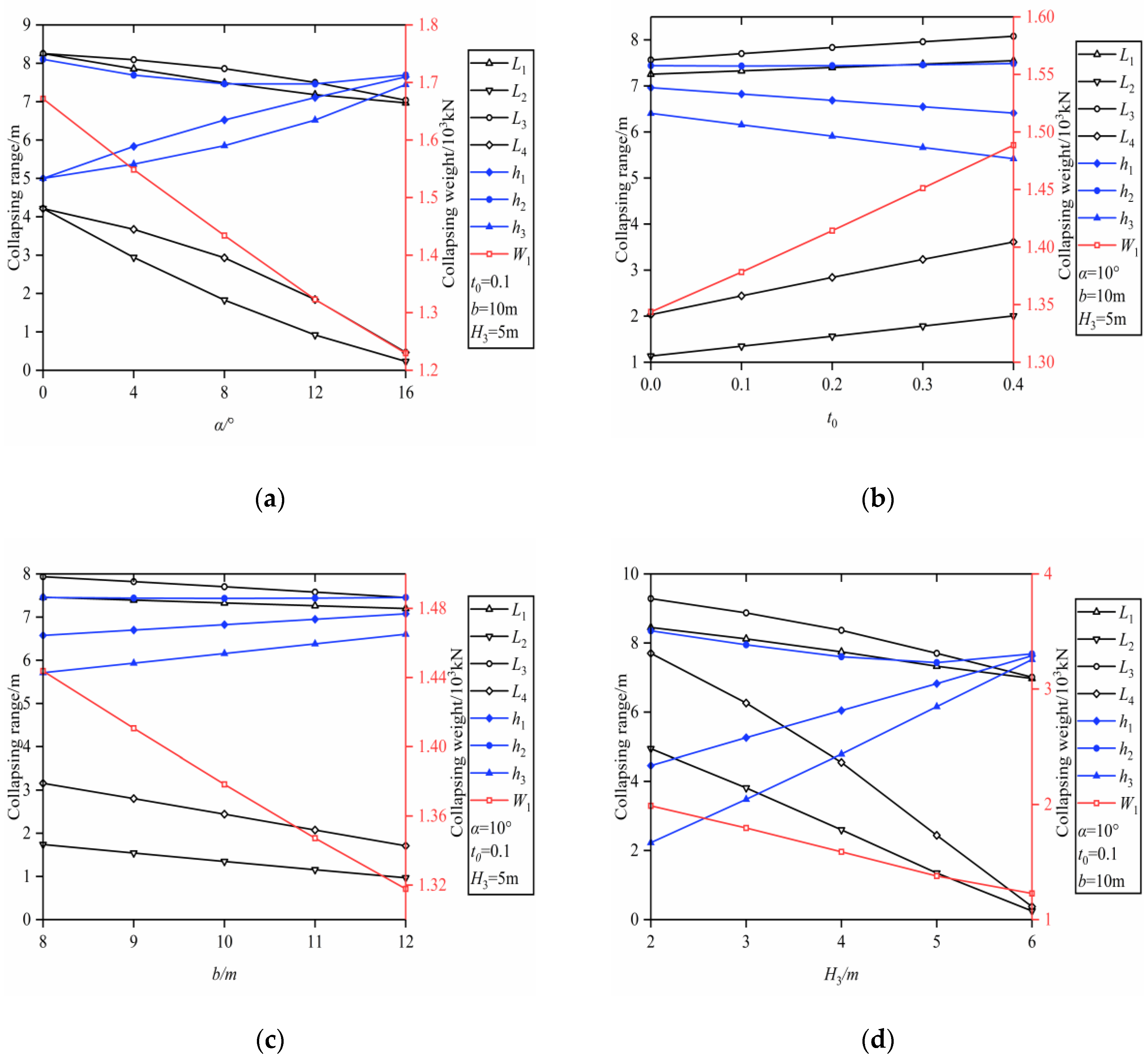
An analysis of the influence of different geometric parameters on the potential collapsing range of rectangular tunnels is shown in Figure 3 when the mechanical parameters of rock mass are given as: A1 = 0.4, B1 = 0.8, σc1 = 8 MPa, γ1 = 20 kN/m—3, A2 = 0.3, B2 = 0.7, σc2 = 10 MPa, and γ2 = 21 kN/m−3. Figure 3 shows that all collapsing widths and total weights of the collapsing block decrease and the heights h1 and h3 increase with the values of α, t0, and b, and the height h2 also increases, whereas the height h2 first decreases and then increases. The influence of the dip angle α of the rock stratum on the potential collapsing range and the collapsing block is symmetrical, that is, L1 = L3 and L2 = L4 only when α = 0. The increases in the value of t0 result in the increase in all potential collapsing widths and height h2, but heights h1 and h3 decrease gradually. Consequently, the inclination in the inclined rock stratum significantly influences the range and total weight of the potential collapsing block in rectangular tunnels so that the inclination of the rock stratum cannot be ignored when investigating tunnel collapse.

4.2.2. Cases with Circular Tunnels

Similarly, according to the previous analysis, the range and the weight of the potential collapsing block in circular tunnels were found to vary with the parameters. Given the relevant calculation parameters, the optimal upper bound solutions of the half widths of the collapsing block for circular tunnels can be solved by combining Equations (75) and (76), and Equations (77) and (78), and the total weight of the collapsing block can be obtained by W2, which can be found in Appendix B.
Table 3 and Table 4 show the calculation results of the range and the total weight of the potential collapsing block in circular tunnels with varying rock mechanical parameters. The half width, the total height, and the total weight of the potential collapsing block in circular tunnels increase with the rock mechanics parameters A1, σc1, A2, and σc2 increasing or B1, γ1, B2, and γ2 decreasing.
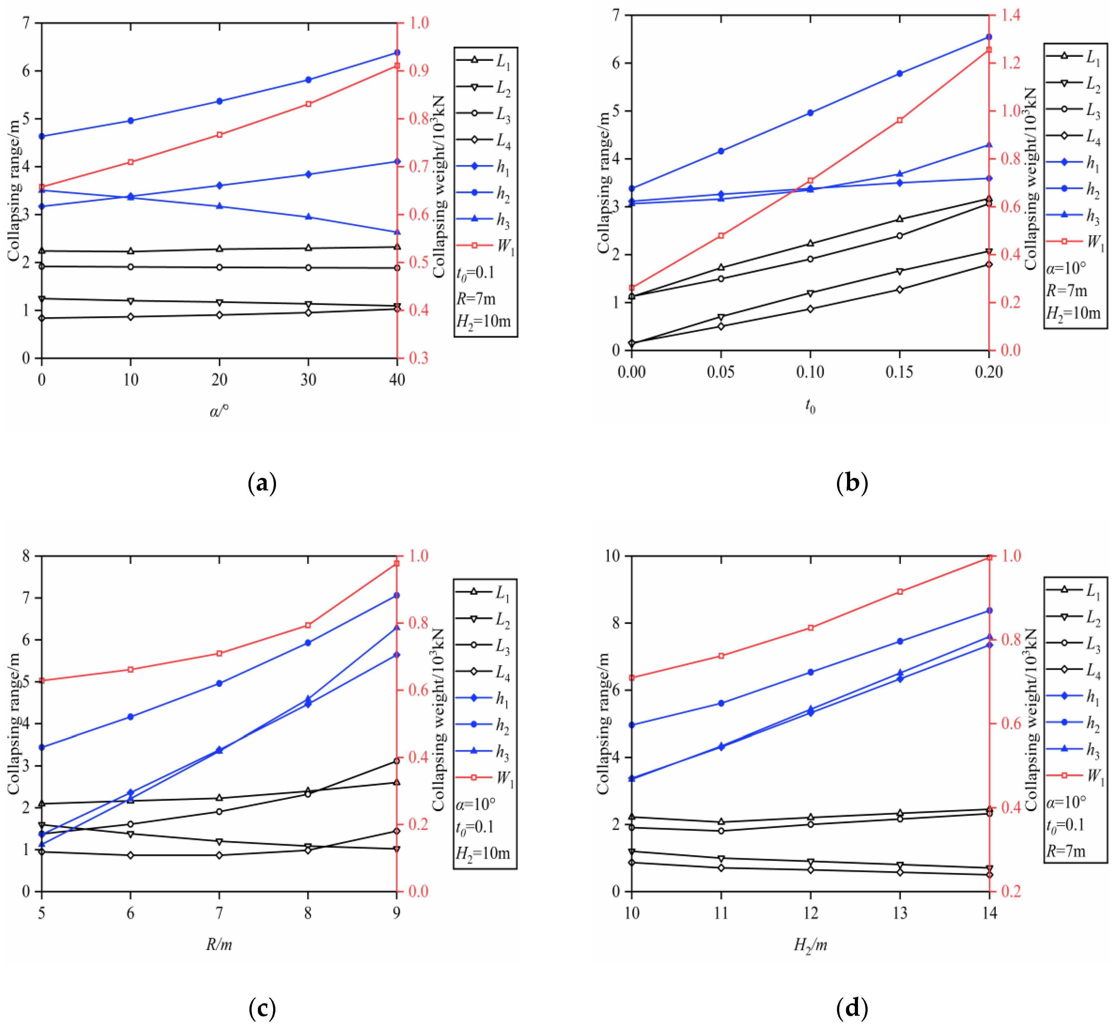
Similarly, we analyzed the influence of the geometric parameters in the collapse mechanism of circular tunnels on the collapse when the mechanical parameters of the rock mass were assumed to be: A1 = 0.1, B1 = 0.8, σc1 = 18 MPa, γ1 = 18 kN/m−3, A2 = 0.5, B2 = 0.9, σc2 = 10 MPa, γ2 = 25 kN/m−3. According to Figure 4a, the increase in α causes the increase in the half widths L1, L4, the total weight, and the heights h1 and h2 of the potential collapsing block, whereas the half widths L2, L3, and the height h3 decrease. Figure 4b reveals that the increase in the increase of t0 causes the increase in the half width, height, and total weight of the collapsing block. Figure 4c indicates that the collapsing weight and range, except L2, increase with t0, but L2 decreases. With the increase in H2, the half widths L1 and L3 first decrease and then increase, the half widths L2 and L4, decrease constantly, while the height and total weight of the collapsing block increase continually.

5. Conclusions

Based on the upper bound theorem of limit analysis and the nonlinear Hoek–Brow yield criterion, a progressive asymmetrical collapse mechanism of rectangular and circular tunnels in inclined rock stratum was constructed to evaluate the stability of deep tunnels. Employing the variational principle, the expressions of detaching curves describing the shape of collapsing blocks were deduced, and then the theoretical formulas of the optimum upper bound solutions of the potential collapsing range and weight were obtained. We compared the findings of our work with the existing research, thereby confirming the rationality and validity of our method.
To describe the influence of variational parameters on the range and the total weight of the potential collapsing block, we completed a parametric sensitivity analysis of the collapse of rectangular and circular tunnels in inclined strata. According to the analytic solutions, there are some differences between the potential collapsing ranges and weights of rectangular and circular tunnels with varying parameters. The variation of the parameters affects the width, total height, and total weight of the collapsing block. The dip angle α of rock stratum plays a marked role in the range and the total weight of the potential collapsing block for rectangular and circular tunnels: the larger the α, the larger the range and total weight. In short, the upper bound theorem of limit analysis is indispensable for evaluating the stability of deep-buried tunnels, and the inclination of rock stratum should receive special attention.

Author Contributions

C.L. proposed theoretical methods and calculations; Z.Z. wrote the manuscript; Y.D. received all the necessary funds.

Funding

This research received no external funding.

Acknowledgments

We thank the State Key Laboratory of Hydraulics and Mountain River Engineering for help with office.

Conflicts of Interest

The authors declare no conflict of interest.

Appendix A. Derivation of the Total Rate of Energy Dissipation

Geotechnical materials obey the associative flow rules, which leads to the coincidence of the plastic potential surface and yield surface, so the plastic potential function can be written as:
Ω = τ n A σ c ( σ n + σ t σ c ) B
Thus, the plastic strain rate is in the form:
{ ε ˙ n = λ Ω σ = λ A B ( σ n + σ t σ c ) B 1 γ ˙ n = λ Ω τ = λ
where λ is a constant. According to the geometric relationships of the collapse mechanism shown in Figure 1 and Figure 2, the plastic strain components can be expressed as:
{ ε ˙ n = 1 1 + f ( x ) 2 v t γ ˙ n = f ( x ) 1 + f ( x ) 2 v t
where t shows the distance between the collapsing boundary and the surrounding rock mass and v indicates the velocity. The dissipated energy at any point on the detaching curve of the collapsing block in rectangular tunnels is:
D = ( σ n ε ˙ n + τ n γ ˙ n ) t = σ t + σ c [ A B f ( x ) ] 1 / ( 1 B ) ( 1 B 1 ) 1 + f ( x ) 2 v
The dissipated energy of the detaching curve in rectangular tunnels can be denoted as:
P D = 0 S D v d s = 0 S D v 1 + f ( x ) 2 d x = 0 S { σ t + σ c [ A B f ( x ) ] 1 1 B ( 1 1 B ) } v d x

Appendix B. Calculation of the Range and Total Weight of the Collapsing Block

F 1 ( L 1 , L 2 ) v = σ t 1 ( L 1 L 2 ) v k 1 γ 1 ( L 1 L 2 ) v 1 B 1 + 1 σ c 1 B 1 1 B 1 A 1 1 B 1 γ 1 1 B 1 [ ( L 1 d 1 γ 1 ) B 1 + 1 B 1 ( L 2 d 1 γ 1 ) B 1 + 1 B 1 ] v σ t 2 L 2 v 1 B 2 + 1 σ c 2 B 2 1 B 2 A 2 1 B 2 γ 2 1 B 2 L 2 B 2 + 1 B 2 v γ 2 k 2 L 2 v ( γ 2 γ 1 ) L 2 h 1 v 1 2 ( γ 1 γ 2 ) L 2 2 v tan α q v L 1 cos π
F 2 ( L 3 , L 4 ) v = σ t 1 ( L 3 L 4 ) v k 3 γ 1 ( L 3 L 4 ) v 1 B 1 + 1 σ c 1 B 1 1 B 1 A 1 1 B 1 γ 1 1 B 1 [ ( L 3 d 3 γ 1 ) B 1 + 1 B 1 ( L 4 d 3 γ 1 ) B 1 + 1 B 1 ] v σ t 2 L 4 v 1 B 2 + 1 σ c 2 B 2 1 B 2 A 2 1 B 2 γ 2 1 B 2 L 4 B 2 + 1 B 2 v γ 2 k 2 L 4 v ( γ 2 γ 1 ) L 4 h 3 v + 1 2 ( γ 1 γ 2 ) L 4 2 v tan α q v L 4 cos π
F 1 ( L 1 , L 2 ) = σ t 1 ( L 1 L 2 ) 1 B 1 + 1 σ c 1 B 1 1 B 1 A 1 1 B 1 γ 1 1 B 1 [ ( L 1 d 1 γ 1 ) B 1 + 1 B 1 ( L 2 d 1 γ 1 ) B 1 + 1 B 1 ] k 1 γ 1 ( L 1 L 2 ) σ t 2 L 2 1 B 2 + 1 σ c 2 B 2 1 B 2 A 2 1 B 2 γ 2 1 B 2 L 2 B 2 + 1 B 2 γ 2 k 2 L 2 ( γ 2 γ 1 ) L 2 h 1 1 2 ( γ 1 γ 2 ) L 2 2 tan α q L 1 cos π = 0
F 2 ( L 3 , L 4 ) = σ t 1 ( L 3 L 4 ) 1 B 1 + 1 σ c 1 B 1 1 B 1 A 1 1 B 1 γ 1 1 B 1 [ ( L 3 d 3 γ 1 ) B 1 + 1 B 1 ( L 4 d 3 γ 1 ) B 1 + 1 B 1 ] k 3 γ 1 ( L 3 L 4 ) σ t 2 L 4 1 B 2 + 1 σ c 2 B 2 1 B 2 A 2 1 B 2 γ 2 1 B 2 L 4 B 2 + 1 B 2 γ 2 k 4 L 4 ( γ 2 γ 1 ) L 4 h 3 + 1 2 ( γ 1 γ 2 ) L 4 2 tan α q L 4 cos π = 0
W 1 = γ 1 B 1 B 1 + 1 A 1 1 B 1 ( γ 1 σ c 1 ) 1 B 1 B 1 [ ( L 2 d 1 γ 1 ) B 1 + 1 B 1 ( L 1 d 1 γ 1 ) B 1 + 1 B 1 ] k 1 γ 1 ( L 1 L 2 ) γ 2 k 2 L 2 + 1 2 ( γ 1 γ 2 ) L 2 2 tan α γ 2 B 2 B 2 + 1 A 2 1 B 2 ( γ 2 σ c 2 ) 1 B 2 B 2 L 2 B 2 + 1 B 2 + γ 1 B 1 B 1 + 1 A 1 1 B 1 ( γ 1 σ c 1 ) 1 B 1 B 1 [ ( L 4 d 3 γ 1 ) B 1 + 1 B 1 ( L 3 d 3 γ 1 ) B 1 + 1 B 1 ] + ( γ 2 γ 1 ) L 2 h 1 k 3 γ 1 ( L 3 L 4 ) γ 2 B 2 B 2 + 1 A 2 1 B 2 ( γ 2 σ c 2 ) 1 B 2 B 2 L 4 B 2 + 1 B 2 γ 2 k 4 L 4 + ( γ 2 γ 1 ) L 4 h 3 1 2 ( γ 1 γ 2 ) L 4 2 tan α
E 1 ( L 1 , L 2 ) = σ t 1 ( L 1 L 2 ) 1 B 1 + 1 σ c 1 B 1 1 B 1 A 1 1 B 1 γ 1 1 B 1 [ ( L 1 d 1 γ 1 ) B 1 + 1 B 1 ( L 2 d 1 γ 1 ) B 1 + 1 B 1 ] k 1 γ 1 ( L 1 L 2 ) 1 2 ( γ 1 γ 2 ) L 2 2 tan α σ t 2 L 2 1 B 2 + 1 σ c 2 B 2 1 B 2 A 2 1 B 2 γ 2 1 B 2 L 2 B 2 + 1 B 2 γ 2 k 2 L 2 ( γ 2 γ 1 ) L 2 h 1 R q cos π ( arcsin L 1 a R + arcsin a R ) + γ 1 [ L 1 R 2 ( L 1 a ) 2 L 1 a 2 R 2 ( L 1 a ) 2 R 2 2 arcsin L 1 a R + a 2 R 2 a 2 + R 2 2 arcsin a R ] = 0
E 2 ( L 3 , L 4 ) = σ t 1 ( L 3 L 4 ) 1 B 1 + 1 σ c 1 B 1 1 B 1 A 1 1 B 1 γ 1 1 B 1 [ ( L 3 d 3 γ 1 ) B 1 + 1 B 1 ( L 4 d 3 γ 1 ) B 1 + 1 B 1 ] k 3 γ 1 ( L 3 L 4 ) 1 2 ( γ 2 γ 1 ) L 4 2 tan α σ t 2 L 4 1 B 2 + 1 σ c 2 B 2 1 B 2 A 2 1 B 2 γ 2 1 B 2 L 4 B 2 + 1 B 2 γ 2 k 4 L 4 ( γ 2 γ 1 ) L 4 h 3 R q cos π ( arcsin L 3 + a R arcsin a R ) + γ 1 [ L 3 R 2 ( L 3 + a ) 2 L 3 + a 2 R 2 ( L 3 + a ) 2 R 2 2 arcsin L 3 + a R + a 2 R 2 a 2 R 2 2 arcsin a R ] = 0
W 2 = γ 1 B 1 B 1 + 1 A 1 1 B 1 ( γ 1 σ c 1 ) 1 B 1 B 1 [ ( L 2 d 1 γ 1 ) B 1 + 1 B 1 ( L 1 d 1 γ 1 ) B 1 + 1 B 1 ] k 1 γ 1 ( L 1 L 2 ) + ( γ 2 γ 1 ) L 2 h 1 + 1 2 ( γ 1 γ 2 ) L 2 2 tan α γ 2 B 2 B 2 + 1 A 2 1 B 2 ( γ 2 σ c 2 ) 1 B 2 B 2 L 2 B 2 + 1 B 2 γ 2 k 2 L 2 γ 1 B 1 B 1 + 1 A 1 1 B 1 ( γ 1 σ c 1 ) 1 B 1 B 1 [ ( L 3 d 3 γ 1 ) B 1 + 1 B 1 ( L 4 d 3 γ 1 ) B 1 + 1 B 1 ] + γ 1 [ L 1 R 2 ( L 1 a ) 2 L 1 a 2 R 2 ( L 1 a ) 2 R 2 2 arcsin L 1 a R + a 2 R 2 a 2 + R 2 2 arcsin a R ] + ( γ 2 γ 1 ) L 4 h 3 1 2 ( γ 1 γ 2 ) L 4 2 tan α + γ 2 B 2 B 2 + 1 A 2 1 B 2 ( γ 2 σ c 2 ) 1 B 2 B 2 L 4 B 2 + 1 B 2 γ 2 k 4 L 4 k 3 γ 1 ( L 3 L 4 ) γ 1 [ L 3 R 2 ( L 3 + a ) 2 L 3 + a 2 R 2 ( L 3 + a ) 2 R 2 2 arcsin L 3 + a R + a 2 R 2 a 2 R 2 2 arcsin a R ]

References

  1. Lee, C.; Wu, B.; Chen, H.; Chiang, K. Tunnel stability and arching effects during tunneling in soft clayey soil. Tunn. Undergr. Space Technol. 2006, 21, 119–132. [Google Scholar] [CrossRef]
  2. Mollon, G.; Dias, D.; Soubra, A.-H. Face stability analysis of circular tunnels driven by a pressurized shield. J. Geotech. Geoenvironmental Eng. 2009, 136, 215–229. [Google Scholar] [CrossRef]
  3. Zhang, C.; Han, K. Collapsed Shape of Shallow Unlined Tunnels Based on Functional Catastrophe Theory. Math. Probl. Eng. 2015, 2015, 1–13. [Google Scholar] [CrossRef]
  4. Han, W.; Wang, G.; Liu, C.; Luan, H.; Wang, K. Time-Dependent Behavior of a Circular Symmetrical Tunnel Supported with Rockbolts. Symmetry 2018, 10, 381. [Google Scholar] [CrossRef]
  5. Liu, X.; Fang, Q.; Zhou, Q.; Liu, Y. Predicting Ground Settlement Due to Symmetrical Tunneling through an Energy Conservation Method. Symmetry 2018, 10, 186. [Google Scholar] [CrossRef]
  6. Min, B.; Zhang, X.; Zhang, C.; Gong, Y.; Yuan, T. Mechanical Behavior of Double-Arch Tunnels under the Effect of Voids on the Top of the Middle Wall. Symmetry 2018, 10, 703. [Google Scholar] [CrossRef]
  7. Mussa, M.H.; Mutalib, A.A.; Hamid, R.; Raman, S.N. Blast Damage Assessment of Symmetrical Box-Shaped Underground Tunnel According to Peak Particle Velocity (PPV) and Single Degree of Freedom (SDOF) Criteria. Symmetry 2018, 10, 158. [Google Scholar] [CrossRef]
  8. Zhang, Z.; Li, L.; Xu, W.; Fu, Y.; Feng, J. Flat-plate roof collapse of shallow caverns and protective measures: A case study of Longyou ancient siltstone caverns. Nat. Hazards 2014, 76, 191–213. [Google Scholar] [CrossRef]
  9. Qin, C.; Chian, S.C.; Yang, X.; Du, D. 2D and 3D limit analysis of progressive collapse mechanism for deep-buried tunnels under the condition of varying water table. Int. J. Rock Mech. Min. Sci. 2015, 80, 255–264. [Google Scholar] [CrossRef]
  10. Monia, C.; Antonio, P.; Nicola, S. Reconstruction of the Geotechnical Model Considering Random Parameters Distributions. Eng. Geol. Soc. Territ. 2015, 2, 1347–1351. [Google Scholar]
  11. Vu-Bac, N.; Lahmer, T.; Zhuang, X.; Nguyen-Thoi, T.; Rabczuk, T. A software framework for probabilistic sensitivity analysis for computationally expensive models. Adv. Eng. Softw. 2016, 100, 19–31. [Google Scholar] [CrossRef]
  12. Pasculli, A.; Calista, M.; Sciarra, N.; Antonio, P.; Monia, C.; Nicola, S. Variability of local stress states resulting from the application of Monte Carlo and finite difference methods to the stability study of a selected slope. Eng. Geol. 2018, 245, 370–389. [Google Scholar] [CrossRef]
  13. Fraldi, M.; Guarracino, F. Limit analysis of collapse mechanisms in cavities and tunnels according to the Hoek–Brown failure criterion. Int. J. Rock Mech. Min. Sci. 2009, 46, 665–673. [Google Scholar] [CrossRef]
  14. Fraldi, M.; Guarracino, F. Analytical solutions for collapse mechanisms in tunnels with arbitrary cross sections. Int. J. Solids Struct. 2010, 47, 216–223. [Google Scholar] [CrossRef]
  15. Huang, F.; Yang, X. Upper bound limit analysis of collapse shape for circular tunnel subjected to pore pressure based on the Hoek–Brown failure criterion. Tunn. Undergr. Space Technol. 2011, 26, 614–618. [Google Scholar] [CrossRef]
  16. Li, T.; Yang, X. Limit analysis of failure mechanism of tunnel roof collapse considering variable detaching velocity along yield surface. Int. J. Rock Mech. Min. Sci. 2017, 100, 229–237. [Google Scholar] [CrossRef]
  17. Yang, X.; Huang, F. Collapse mechanism of shallow tunnel based on nonlinear Hoek–Brown failure criterion. Tunn. Undergr. Space Technol. 2011, 26, 686–691. [Google Scholar] [CrossRef]
  18. Yang, X.; Huang, F. Three-dimensional failure mechanism of a rectangular cavity in a Hoek–Brown rock medium. Int. J. Rock Mech. Min. Sci. 2013, 61, 189–195. [Google Scholar] [CrossRef]
  19. Qin, C.; Yang, X.; Pan, Q.; Sun, Z.; Wang, L.; Miao, T. Upper bound analysis of progressive failure mechanism of tunnel roofs in partly weathered stratified Hoek–Brown rock masses. Int. J. Rock Mech. Min. Sci. 2015, 74, 157–162. [Google Scholar] [CrossRef]
  20. Qin, C.; Chian, S.C. 2D and 3D stability analysis of tunnel roof collapse in stratified rock: A kinematic approach. Int. J. Rock Mech. Min. Sci. 2017, 100, 269–277. [Google Scholar] [CrossRef]
  21. Yang, X.L.; Zhou, T.; Li, W.T. Reliability analysis of tunnel roof in layered Hoek-Brown rock masses. Comput. Geotech. 2018, 104, 302–309. [Google Scholar] [CrossRef]
  22. Chen, W. Limit Analysis and Soil Plast. Amsterdam; Elsevier: Amsterdam, The Netherlands, 1975. [Google Scholar]
  23. Huang, M.; Li, S.; Yu, J.; Tan, J.Q.W. Continuous field based upper bound analysis for three-dimensional tunnel face stability in undrained clay. Comput. Geotech. 2018, 94, 207–213. [Google Scholar] [CrossRef]
  24. Hoek, E.; Brown, E.T. Underground Excavations in Rock; Institute of Mining and Metallurgy: London, UK, 1980. [Google Scholar]
  25. Hoek, E. Empirical strength criterion for rock masses. J. Geotech. Eng. Div. ASCE 1980, 106, 1013–1035. [Google Scholar]
  26. Hoek, E.; Carranza-Torres, C.T.; Corkum, B. Hoek-Brown failure criterion-edition. In Proceedings of the 5th North American Rock Mechanics Symposium, Toronto, ON, Canada, 31 May–1 June 2002; pp. 267–273. [Google Scholar]
  27. Hoek, E.; Brown, E.T. Practical Estimates of Rock Mass Strength. Int. J. Rock Mech. Min. Sci. 1997, 34, 1165–1186. [Google Scholar] [CrossRef]
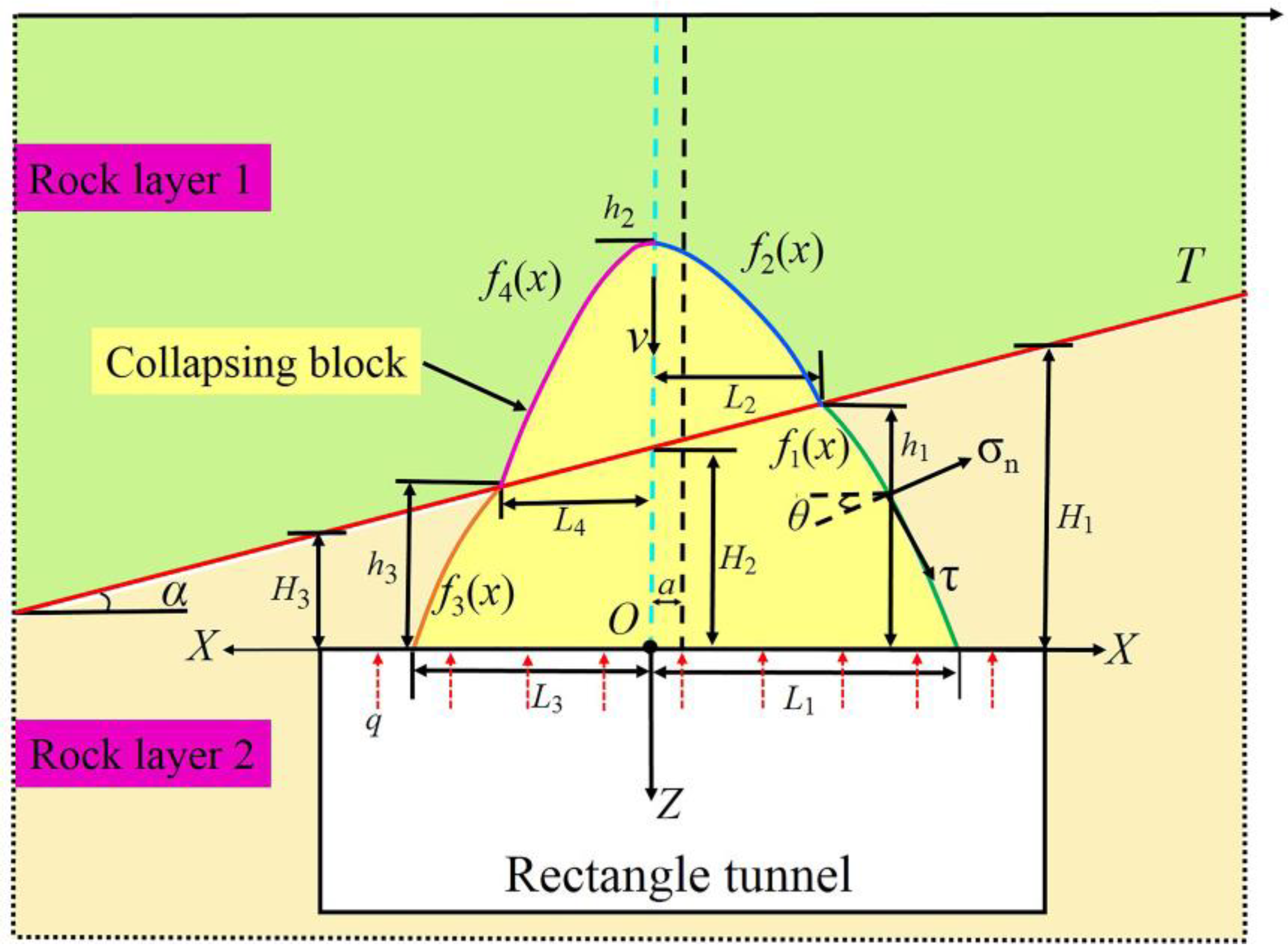
Figure 1. Progressive asymmetrical collapse mechanism of rectangular tunnels in an inclined rock stratum.
Symmetry 11 00904 g001
Figure 2. Progressive asymmetrical collapse mechanism of circular tunnels in an inclined rock stratum.
Symmetry 11 00904 g002
Figure 3. Collapse failure of rectangular tunnels with different geometric parameters: (a) different dip angle α; (b) different t0; (c) different b; (c) different H3.
Symmetry 11 00904 g003
Figure 4. Collapse failure of circular tunnels with different geometric parameters: (a) different dip angle α; (b) different t0; (c) different R; (c) different H2.
Symmetry 11 00904 g004
Table 1. The collapse failure of rectangular tunnels with different physical parameters in the lower rock strata.
A1B1σc1
/MPa
γ1
/kN·m−3
L1
/m
L2
/m
L3
/m
L4
/m
h1
/m
h2
/m
h3
/m
W1
/103 kN
0.10.88201.880.371.920.446.656.756.510.34
0.20.88203.720.693.850.926.716.946.430.67
0.30.88205.530.985.781.496.767.146.321.01
0.40.88207.331.357.702.446.827.436.161.38
0.50.88209.162.239.985.416.988.235.632.11
0.40.768208.802.429.234.497.018.425.791.94
0.40.778208.402.058.833.886.958.065.901.76
0.40.788208.031.758.443.336.907.786.001.61
0.40.798207.671.538.072.856.867.586.091.48
0.40.87206.020.176.070.296.626.656.540.92
0.40.88.5207.851.868.223.186.917.886.031.58
0.40.89208.322.328.633.777.008.325.921.76
0.40.810209.103.129.294.717.149.165.762.10
0.40.88197.841.858.313.326.917.876.001.59
0.40.88216.860.917.101.596.757.096.311.22
0.40.88226.430.536.550.866.686.846.431.11
0.40.88236.070.226.100.336.636.676.531.04
(A2 = 0.3, B2 = 0.7, σc2 = 10 MPa, γ2 = 21 kN/m−3, t0 = 0.1, b = 10 m, α = 10°, H3 = 5 m).
Table 2. The collapse failure of rectangular tunnels with different physical parameters in the upper rock strata.
A2B2σc2
/MPa
γ2
/kN·m−3
L1
/m
L2
/m
L3
/m
L4
/m
h1
/m
h2
/m
h3
/m
W1
/103 kN
0.280.710217.321.437.672.646.847.576.121.40
0.320.710217.331.307.732.336.827.346.181.37
0.340.710217.341.277.762.276.817.286.191.36
0.360.710217.341.267.782.236.817.236.191.36
0.30.410217.411.268.442.816.816.816.091.41
0.30.510217.401.258.292.646.816.846.121.40
0.30.610217.381.248.012.346.806.986.171.37
0.30.6510217.361.247.862.266.817.136.191.36
0.30.78216.981.037.041.566.777.236.311.21
0.30.79217.131.177.311.916.797.316.251.28
0.30.711217.571.588.283.226.877.606.021.53
0.30.712217.891.899.054.286.927.835.831.76
0.30.710227.321.357.682.456.837.456.161.43
0.30.710237.311.367.662.456.837.466.161.48
0.30.710247.301.367.632.456.837.486.151.53
0.30.710257.291.377.612.466.837.506.151.58
(A1 = 0.4, B1 = 0.8, σc1 = 8 MPa, γ1 = 20 kN/m−3, t0 = 0.1, b = 10 m, α = 10°, H3 = 5 m).
Table 3. The collapse failure of circular tunnels with different physical parameters in the lower strata.
A1B1σc1
/MPa
γ1
/kN·m−3
L1
/m
L2
/m
L3
/m
L4
/m
h1
/m
h2
/m
h3
/m
W2
/103 kN
0.100.818182.231.201.910.873.384.963.350.71
0.110.818182.361.222.040.903.415.033.400.74
0.120.818182.501.232.240.963.455.113.480.79
0.130.818182.591.232.421.023.485.163.560.83
0.140.818182.741.252.621.093.525.253.650.87
0.100.7218182.881.292.881.233.575.433.770.94
0.100.7418182.711.262.551.083.525.293.610.86
0.100.7618182.551.242.320.993.475.173.510.81
0.100.7818182.401.222.100.923.435.073.420.76
0.100.817181.970.991.520.553.294.563.260.57
0.100.819182.031.041.610.633.314.663.280.60
0.100.820182.111.101.710.703.344.763.300.64
0.100.821182.181.151.810.783.364.873.330.67
0.100.818172.291.231.980.923.405.023.370.72
0.100.818192.231.191.850.823.384.953.330.70
0.100.818202.201.181.790.783.374.913.320.69
0.100.818212.181.161.740.743.364.883.310.68
(A2 = 0.5, B2 = 0.9, σc2 = 10 MPa, γ2 = 25 kN/m−3, t0 = 0.1, R = 7 m, α = 20°, H3 = 10 m).
Table 4. The collapse failure of circular tunnels with different physical parameters in the upper strata.
A2B2σc2
/MPa
γ2
/kN·m−3
L1
/m
L2
/m
L3
/m
L4
/m
h1
/m
h2
/m
h3
/m
W2
/103 kN
0.20.910251.901.081.610.763.296.833.260.66
0.30.910252.141.141.800.813.355.843.320.69
0.40.910252.251.191.870.853.385.343.340.71
0.60.910252.291.231.930.883.404.763.360.71
0.50.510252.411.342.020.963.453.653.380.724
0.50.610252.411.332.010.963.453.723.380.723
0.50.710252.381.312.000.943.443.913.370.723
0.50.810252.331.271.970.923.424.323.370.720
0.50.921252.010.991.690.663.304.643.300.61
0.50.922252.071.041.730.703.324.713.310.63
0.50.923252.131.091.780.753.344.793.320.66
0.50.924252.191.151.840.803.364.883.340.68
0.50.910212.521.442.171.113.505.413.420.715
0.50.910222.451.382.091.043.465.293.400.714
0.50.910232.381.322.020.973.445.183.380.713
0.50.910242.321.261.960.923.415.083.360.712
(A1 = 0.1, B1 = 0.8, σc1 = 18 MPa, γ1 = 18 kN/m−3, t0 = 0.1, R = 7 m, α = 20°, H3 = 10 m).