Article

Reversible Steganographic Scheme for AMBTC-Compressed Image Based on (7,4) Hamming Code

1
School of Electronic and Information Engineering, Fuqing Branch of Fujian Normal University, Fuzhou 350300, China
2
Engineering Research Center for ICH Digitalization and Multi-source Information Fusion, (Fuqing Branch of Fujian Normal University), Fujian Province University, Fuzhou 350300, China
3
Department of Computer Science and Information Management, Providence University, Taichung 43301, Taiwan
4
Department of Information Engineering and Computer Science, Feng Chia University, Taichung 40724, Taiwan
*
Authors to whom correspondence should be addressed.
Symmetry 2019, 11(10), 1236; https://doi.org/10.3390/sym11101236
Submission received: 22 August 2019 / Revised: 16 September 2019 / Accepted: 20 September 2019 / Published: 3 October 2019
(This article belongs to the Special Issue Information Technologies and Electronics)

Abstract

:
In recent years, compression steganography technology has attracted the attention of many scholars. Among all image compression method, absolute moment block truncation coding (AMBTC) is a simple and effective compression method. Most AMBTC-based reversible data hiding (RDH) schemes do not guarantee that the stego AMBTC compression codes can be translated by the conventional AMBTC decoder. In other words, they do not belong to Type I AMBTC-based RDH scheme and easily attract malicious users’ attention. To solve this problem and enhance the hiding capacity, we used (7,4) hamming code to design a Type I AMBTC-based RDH scheme in this paper. To provide the reversibility feature, we designed a prediction method and judgement mechanism to successfully select the embeddable blocks during the data embedding phase and data extraction and recovery phase. In comparing our approach with other BTC-based schemes, it is confirmed that our hiding capacity is increased while maintaining the limited size of the compression codes and acceptable image quality of the stego AMBTC-compressed images.

1. Introduction

Data hiding, also called steganography [1], is the study of embedding secret message into innocuous cover media [2], such as images, audio signals, and videos files, to protect the confidentiality of the hidden data. Digital images are often used as the cover media because they can be accessed easily and can provide abundant redundancies for concealing data. According to the recoverability of the cover image after the extraction of hidden data, data hiding can be classified into two categories, i.e., conventional data hiding and reversible data hiding (RDH). RDH is crucial for some specific applications, such as medical imaging, remote sensing, and military communications. The first RDH was proposed by Barton in 1997 [3]. In Barton’s approach, the bits to be overlaid were compressed in advance and then added to the secret bit string, after which the generated secret bit string was embedded into the data blocks of the images. Since then, researchers inspired by Barton’s idea have proposed various RDH approaches, including difference expansion (DE) [4,5], histogram shifting [6,7,8], and prediction-error [9,10,11]. In 2003, DE was introduced by Tian et al. by embedding the secret message into the differences between two adjacent pixels [4]. In 2006, Ni et al. developed a different RDH approach based on histogram modification. Their approach used the zero or the minimum pixel value of the histogram of an image as the peak value, and then they slightly modified peak value and shifted the related pixel values to embed secret data [6]. In 2008, Lin et al. transformed the original image into a difference image before using the histogram shifting technique to make sure the frequency of peak value is as largest as possible and ascertained that the hiding capacity was increased significantly [7]. In 2011, Li et al. designed a new hybrid RDH method based on prediction-error expansion (PEE), adaptive embedding, and pixels’ selection [9]. Subsequently, many scholars used Li et al.’s approach and designed various improved RDH schemes based on PEE. However, these schemes were designed for images in the spatial domain rather than images in the compression domain, but the latter demand of compression techniques has increased gradually as people have become familiar with the capability of transmitting or sharing image files over the Internet. Therefore, it is essential to explore and design RDHs for compression-domain images.
Compression techniques are designed to solve the problem of limited bandwidth since multimedia files, such as image, audio, and video files, are quite large. The general compression techniques include discrete cosine transform (DCT) [12], discrete wavelet transform (DWT) [13], vector quantization (VQ) [14], and side match vector quantization (SMVQ) [15]. The latter two famous block-based image compression techniques, i.e., VQ and SMVQ, attracted the attention of researchers when they tried to design RDHs for images in the compression domain. In 2005, Yang et al. [16] applied modified, fast-correlation vector quantization (MFCVQ) to design a reversible watermarking scheme for VQ-compressed images. However, the weakness of their scheme is their low hiding capacity. To overcome this disadvantage, Lu et al. [17] proposed an RDH method based on VQ-index residual value coding technique. In 2006, Chang et al. [18] used a real codeword that could be mapped to an index in the SMVQ’s codebook and a derived codeword that did not exist in the SMVQ’s codebook to design their RDH strategy for SMVQ-compressed images. Inspired by Chang et al.’s idea, in 2011, Chiou et al. [19] proposed an RDH scheme with enhanced hiding capacity that was also based on SMVQ to improve the hiding capacity and visual quality of steo-image. In Chiou et al.’s scheme, one secret bit is concealed into each pixel of the residual blocks.
In addition to VQ and SMVQ, block truncation coding (BTC) is the other efficient, lossy, block-based image compression technique. BTC technique was first proposed by Delp and Mitchell in 1979 [20] and has been used for compressing Mars Pathfinder’s rover images [21]. Later, Lema and Mitchell [22] proposed the absolute mean block truncation coding (AMBTC) method to prompt the compression performance. After learning about the features of BTC and AMBTC, many scholars designed BTC-based or AMBTC-based RDHs. In general, these RDHs can be classified into two types, i.e., (1) Type I in which the stego codes can be decoded correctly via a conventional BTC or AMBTC decoder [23,24,25] and a recovered image always can be constructed and (2) Type II in which the stego codes have specific coding structures [26,27,28] and cannot be translated by standard BTC or AMBTC decoders. In other words, as long as malicious attackers use BTC or AMBTC decoders to decode the stego codes, those that cannot be decoded will be identified easily because they carry some valuable information. To avoid drawing the attention of attackers, in this paper, we tried to design a Type I-RDH scheme for AMBTC-compressed images.
Inspired by Chang et al.’s high payload data hiding scheme for compressed images with (7,4) hamming code [29], several data hiding schemes based on (7,4) hamming code were proposed sequentially [30,31], but they were not reversible. In 2017, Biswapati et al. utilized (7,4) hamming code to design a partial RDH which allows the restored image to be very similar to its original image [32]. In 2018, the same research team designed a dual image-based RDH scheme using (7,4) hamming code [33]. According to the lectures we have collected to date, no one has used (7,4) hamming code to design RDH for a single, AMBTC-compressed image. However, (7,4) hamming code has a unique feature in that it can hide three secret bits into a seven-bit stream only at the cost of modifying a single bit. To take advantage of (7,4) hamming code, in this paper we introduce an RDH scheme using (7,4) hamming code that embeds secret data based on the relationship of the high-low mean tables and also into the bitmaps. In other words, the original AMBTC compression codes can be completely restore once the hidden data has been extracted with our proposed scheme. There is no distortion between our restored compression codes and the original AMBTC compression codes.
The rest of the paper is organized as follows. Section 2 introduces the AMBTC scheme and (7,4) hamming code. Section 3 illustrates the use of the proposed scheme for embedding and extracting data using the high-low mean tables and bitmap. In Section 4, we describe the experiments we conducted and compare our proposed RDH scheme with other Type I AMBTC-based RDH schemes. Concluding remarks are given in Section 5.

2. Related Works

In this section, we briefly describe the concepts of AMBTC and (7,4) hamming code and matrix embedding.

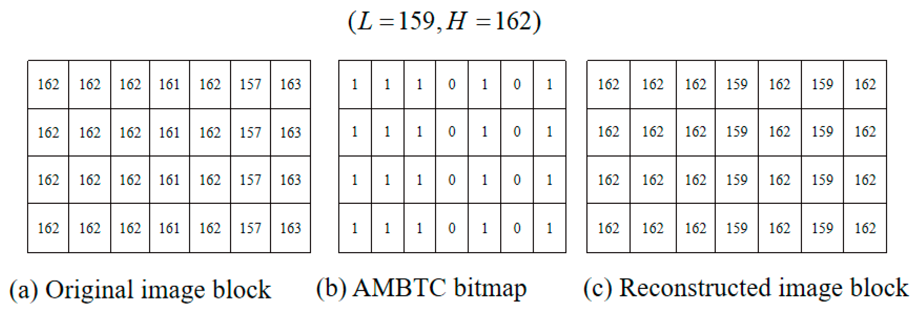
2.1. Absolute Moment Block Truncation Coding (AMBTC)

In 1984, Lema and Mitchell [22] proposed a new compression technique for reconstructing good images that preserved the local characteristics of the spatial blocks of the image. After dividing an image into 4 × 4 non-overlapping blocks, for each block, their method computes the mean and the standard deviation of the sample, i.e.,
η = 1 m i = 1 m x i and σ = 1 m i = 1 m | x i η |
where m is the total number of pixels in the block, and   x i is the gray value of each pixel. Both values are transmitted along with a bit plane that contains ones in those positions where x i > η and zeros otherwise. At the recipient, a reconstructed block can be obtained with two quantizers: the low mean value L for group-0 and the high mean value H for group-1 that preserves the sample mean and variance [22] according to Equation (2),
L = η m × σ 2 ( m q ) and H = η + m × σ 2 q
where q is the number of pixels that are greater than or equal to η.
Figure 1 shows an example of the results of encoding and decoding using the AMBTC compression method. Note that, in the original AMBTC encoding phase, an image is generally divided into non-overlapping blocks, and the size of each block is 4 × 7 pixels. However, Figure 1a shows that the original image block was 4 × 7. This is because a block defined in our proposed RDH scheme is 4 × 7 pixels. To give readers consistent representation and a better understanding, a block with the same size is demonstrated in Figure 1a. Even though the size of the block is different from the conventional AMBTC, the other operations in the encoding and decoding phases are the same as they are in the conventional AMBTC. The mean value was obtained, i.e., η = 161.28. We computed the value of L = 159 by averaging the pixel values that were less than 161.28, and the result is rounded to the nearest integer. Similarly, we computed the value. Subsequently, if the pixel values were less than 161.28, their corresponding bits were set as “0” in the bitmap; otherwise, their corresponding bits were set as “1.” Figure 1b shows the corresponding AMBTC bitmap that was derived from a given block. As shown in Figure 1a, its AMBTC compressed trio is denoted as (L= 159, H = 162, bitmap = 1110101; 1110101; 1110101; 1110101). To decode the compressed trio, the “0” and “1” in the bitmap were replaced by L = 159 and H = 162, respectively. Finally, a reconstructed image block was generated, as shown in Figure 1c.

2.2. (7,4) Hamming Code

(7,4) hamming code is a kind of linear code for the correction of block errors. It has been used extensively by researchers because it can identify a single bit error in a block of 7-bits and then correct it. In this paper, (7,4) hamming coding was used to operate the modification of bits. Four data bits, i.e., d = ( d 1 , d 2 , d 3 , d 4 ) , d were encoded into seven bits by adding three parity bits, i.e., c = ( c 1 , c 2 , c 3 ) . The encoding rule must satisfy Equation (3).
{ c 1 = d 1 d 2 d 3 , c 2 = d 1 d 3 d 4 , c 3 = d 2 d 3 d 4 ,
where is the exclusive-OR operation. By transforming Equation (3) into a matrix, the result is transposed, i.e.,
[ c 1 c 2 c 3 ] = [ 1 1 1 0 1 0 1 1 0 1 1 1 ] [ d 1 d 2 d 3 d 4 ] [ d 1 d 2 d 3 d 4 ] [ 1 1 0 1 0 1 1 1 1 0 1 1 ] = [ c 1 c 2 c 3 ] .
when the unit identity is added, the form is changed as shown below:
[ d 1 d 2 d 3 d 4 ] [ 1 0 0 0 1 1 0 0 1 0 0 1 0 1 0 0 1 0 1 1 1 0 0 0 1 0 1 1 ] = [ d 1 d 2 d 3 d 4 d 5 d 6 d 7 ] ,
G = [ I k Q k × r ] = [ 1 0 0 0 1 1 0 0 1 0 0 1 0 1 0 0 1 0 1 1 1 0 0 0 1 0 1 1 ] ,
For decoding, a parity check matrix, H0, is required. This matrix can be obtained from Equation (7) by changing Equation (3) to Equation (8).
{ c 1 d 1 d 2 d 3 = 0 , c 2 d 1 d 3 d 4 = 0 , c 3 d 2 d 3 d 4 = 0 .
Then, convert it into a matrix.
[ 1 1 1 0 1 0 0 1 0 1 1 0 1 0 0 1 1 1 0 0 1 ] [ d 1 d 2 d 3 d 4 c 1 c 2 c 3 ] = [ 0 0 0 ] .
Finally, a parity check matrix H 0 = [ 1 1 1 0 1 0 0 1 0 1 1 0 1 0 0 1 1 1 0 0 1 ] 3 × 7 is generated.
The four codes and three parity bits are sent to receiver. At the recipient, the received 7-bits codeword, R = (1000110), is multiplied by the parity check matrix, H0, and, then, modulo 2 is conducted to determine whether an error occurred. The computed result is called a syndrome. If the syndrome is “000,” it means there is no error. If a single bit error occurs, the syndrome will not be equal to “000.” Assume the received codeword R, has one error in the first row of the G matrix, (ex. R = (1100110), the calculated syndrome is “101,” which is identical to the second column of H0, and R is corrected by R = ( 1100110 ) e 2 = ( 1000110 ) where e i is the ith unit vector of length seven ( e 2 is a zero vector of length seven with a 1 located at the second position, e 2 = ( 0100000 ) ). Then, we determine the correct original data bits by ignoring the last three bits, i.e., d = ( 1000 ) .

3. Proposed Scheme

In this paper, we propose a (7,4) hamming code-based RDH for AMBTC-compressed images. Our proposed RDH scheme consists of two phases, i.e., 1) the data embedding phase and 2) the data extraction and recovery phase. In the data embedding phase, after AMBTC encoding, the cover image is divided into non-overlapping 4 × 7-sized blocks, where each block contains only different values of high mean (H), low mean (L), and 4 × 7-bits bitmap. The secret bits can be concealed by changing the order between H and L, and they also can be embedded into the 4 × 7-bits bitmap with (7,4) hamming code. In the former, we can extract a secret bit and losslessly reconstruct the stego image to the AMBTC-compressed image. However, for embedding data on a bitmap with (7,4) hamming code, three secret bits can be hidden into each 1 × 7-sized bitmap. To ensure that the modified bit of 1 × 7-bits bitmap can be restored, a prediction method and a judgment mechanism which is workable during both the data embedding phase and data extraction/recovery phase are designed in our proposed RDH scheme. The proposed prediction method and judgment mechanism are our core concept and they are introduced initially in Section 3.1, and the data embedding phase and data extraction/recovery phases are presented in detail in Section 3.2 and Section 3.3, respectively. To give clear explanations for both phases, an example is provided to demonstrate our proposed data embedding and data extraction/recovery operations.

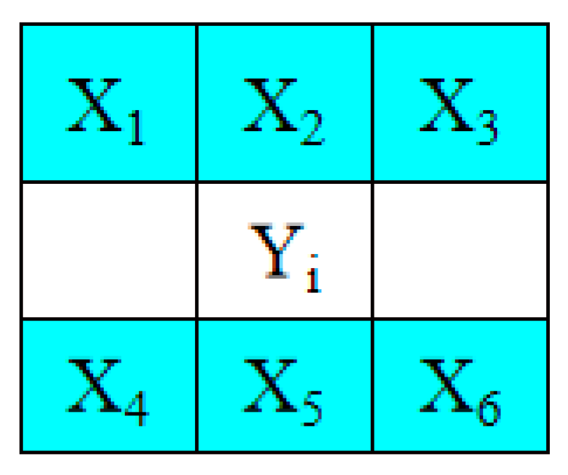
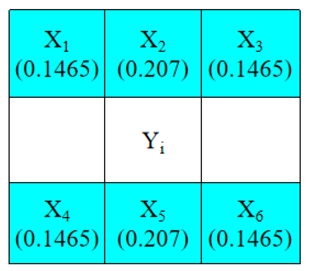
3.1. Prediction Method and Selections of Embeddable Blocks

To embed secret data into two quantizers, the prediction method must be used, and it must be derived from the original neighboring pixels. Here, a simple prediction is conducted, and, first, a 3 × 3-pixels window is constructed, as shown in Figure 2.
To predict Y i , we define its prediction value, Y i , can be derived from its neighboring six pixels as
Y i = λ 1 X 1 + λ 2 X 2 + λ 3 X 3 + λ 4 X 4 + λ 5 X 5 + λ 6 X 6 .
where Y i are six neighboring pixels of Y i in the image, and λ 1 , λ 2 , , λ 6 are the coefficients of X i ( i = 1 , 2 , , 6 ) , respectively. The expression λ 1 + λ 2 + + λ 6 = 1 must be satisfied. If the distance between Y i and each pixel, X i ( i = 1 , 2 , , 6 ) , is not considered, λ i ( i = 1 , 2 , , 6 ) is always 1/6. However, if the Euclidean distance between Y i and X i ( i = 1 , 2 , , 6 ) is considered, their corresponding coefficients can be defined as: λ 1 : λ 2 = 1 : 2 , λ 2 = λ 5 , λ 1 = λ 3 = λ 4 = λ 6 , and λ 1 + λ 2 + + λ 6 = 1 . Thus, six coefficients are obtained as λ 1 = λ 3 = λ 4 = λ 6 = 0.1465 , λ 2 = λ 5 = 0.207 , as shown in Figure 3.
For the pixels that are located in the left border of an image, we define that the prediction value, Y i , only requires its four neighboring pixels, i.e.,
Y i = λ 1 X 1 + λ 2 X 2 + λ 4 X 4 + λ 5 X 5 .
where λ 1 = λ 4 , λ 2 = λ 5 , λ 1 : λ 2 = 1 : 2 and λ 1 + λ 2 + λ 4 + λ 5 = 1 . Thus, the four coefficients can be computed as λ 1 = λ 4 = 0.20 , λ 2 = λ 5 = 0.29 . In a similar manner, the prediction pixels Y i located at the right border of an image can be derived from
Y i = λ 2 X 2 + λ 3 X 3 + λ 5 X 5 + λ 6 X 6 .
where the coefficients are defined as λ 2 = λ 5 = 0.29 , λ 3 = λ 6 = 0.20 .
Subsequently, given a constructed image, the embeddable blocks can be determined by Equation (12) to maintain the reversible feature based on the difference between the reconstructed pixels and their prediction values
| Y i Y i | < 0.5 × ( H L ) ( H L ) .
Note that the block is defined as a 1 × 7-sized block instead of a 4 × 7-sized block when determining whether or not it is embeddable. Since it is a reconstructed image, each 1 × 7-sized block contains, at most, only two different values, i.e., either L or H. It must be determined whether the blocks located in the even rows are embeddable or not. Blocks located in the odd rows are treated as reference blocks to ensure that all of the embedded blocks can be completely restored to the original AMBTC reconstructed blocks after the hidden data are extracted. For a 1 × 7-sized block located in an even row, Equation (12) is used to check seven reconstructed pixels. If Equation (12) is satisfied for all seven reconstructed pixels, the currently processing block is embeddable. If any pixel in a 1 × 7-sized block does not satisfy Equation (12), the currently processing block is un-embeddable.
Our proposed prediction method can be used to assist the selection of embeddable blocks irrespective of whether the process is in the data embedding phase or the data extraction and recovery phase. Note that the original neighboring pixels are considered to compute the prediction values during the data embedding phase. By contrast, the reconstructed pixels are considered during the data extraction and recovery phase. However, even in the data extraction phase, Equation (12) always holds because we assume that, if Y i is H, then Y i T is L, and vice versa.
H L = | Y i T Y i | = | Y i T Y i Y i + Y i | .
Therefore, from
160 × 0.146 + 160 × 0.207 + 155 × 0.146 + 157 × 0.146 + 157 × 0.207 + 153 × 0.146 = 157.18
and according to Equation (12), Equation (13) can be derived as
| Y i T Y i | > 0.5 × ( H L ) ( H L ) .
Since the 1 × 7-sized blocks located in the odd rows are treated as reference blocks and since not all 1 × 7-sized blocks located in the even rows are embeddable for a given AMBTC reconstructed image, a location map LP recording is required for the blocks located in the even rows. In the location map LP, “1” indicates that the corresponding block is embeddable; and “0” indicates that the corresponding block is unembeddable. Then, the location map LP is treated as secret data, and it is embedded into the bitmap in front of the secret message.

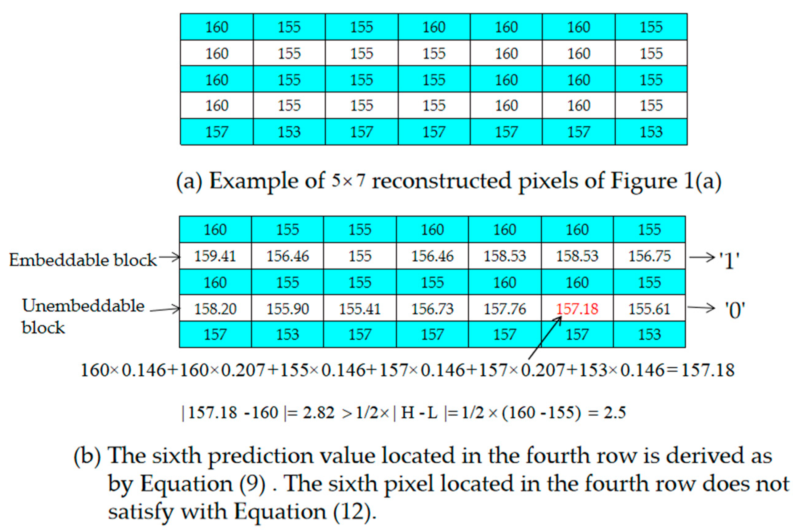
Example of the Selection of Embeddable Blocks

Let us assume that the size of a grayscale image is 512 × 512 pixels and that it is divided into non-overlapping 4 × 7-sized blocks. Here, we only take the 5×7 reconstructed pixels for example. It is noted the first four rows map to a 4 × 7-sized block. Therefore, the first four rows only contain two different values, which map to the same quantizer pair, which is L (= 155) and H (= 160). However, the last row maps to the other 4 × 7-sized block, and the two values are different, i.e., L (= 153) and H (= 157).
Equation (12) is satisfied for all pixels located in the second row. Therefore, it is noted as “0” to indicate that the second row is embeddable in the location map. In contrast, the sixth prediction value located in the fourth row is derived by Equation (9) as
160 × 0.146 + 160 × 0.207 + 155 × 0.146 + 157 × 0.146 + 157 × 0.207 + 153 × 0.146 = 157.18
The sixth predicted value located in the fourth row does not satisfy Equation (12).
| 157 . 18 - 160 | = 2 . 82 > 1 / 2 × | H - L | = 1 / 2 × ( 160 - 155 ) = 2 . 5 .
Therefore, it is marked in red as shown in Figure 4b. Since the fourth row has one pixel that does not satisfy Equation (12), it is noted as “0” in the location map to indicate that the fourth row is unembeddable.

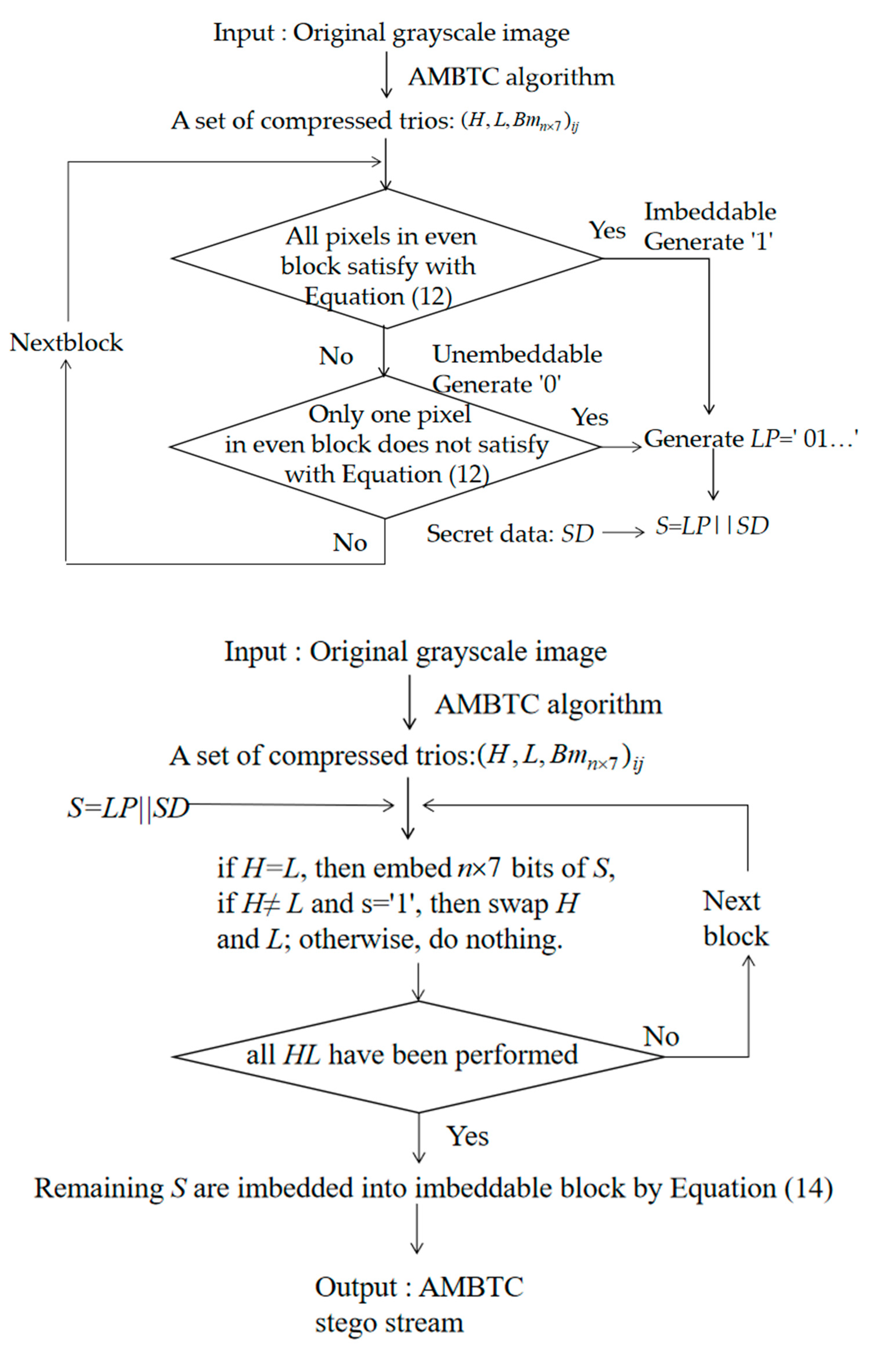
3.2. Data Embedding Phase

All 1 × 7-sized blocks are determined to be embeddable or unembeddable by using the location map. The data embedding phase is described in detail in this subsection. Figure 5 shows the flowchart of the embedding phase for embeddable blocks.
Input: Original grayscale image.
Output: AMBTC-compressed stego bitstream.
  • Step 1. Partition the original image into n × 7 pixel blocks and conduct AMBTC encoding; a set of compressed trios, i.e., ( H , L , B m n × 7 ) i , j , is obtained, where H is the high mean table, L is the low mean table, B m n × 7 is the bitmap, n = 4, and ( i , j ) is the coordinate of the n × 7 pixel block where i   =   1 , 2 , , 128 and j = 1 , 2 , , 73 .
  • Step 2. Based on their positions, use the pixels located in the odd rows to predict the pixels located in the even rows with Equations (9)–(11), respectively. If all of the pixels in a 1 × 7-sized block satisfy Equation (13), determine the block to be embeddable and denote it as “1” in the location map, LP. Otherwise, denote it as “0” in the location map, LP.
  • Step 3. After all blocks have been evaluated, concatenate LP and secret data SD as the final secret message S, where S = LP||SD, and “||” denotes the concatenation of LP and SD.
  • Step 4. Scan all AMBTC-compressed blocks in a zig-zag direction to embed the final secret message, S, into bitmap Bm. If H = L, 4 × 7 bits of S are selected and used to replace the original Bm. If not, H is not equal to L, select one bit, s, of S and embed it into the H and L pair by swapping the order when s = 1. Note that, if HL and s = 0, then the order of H and L is not changed.
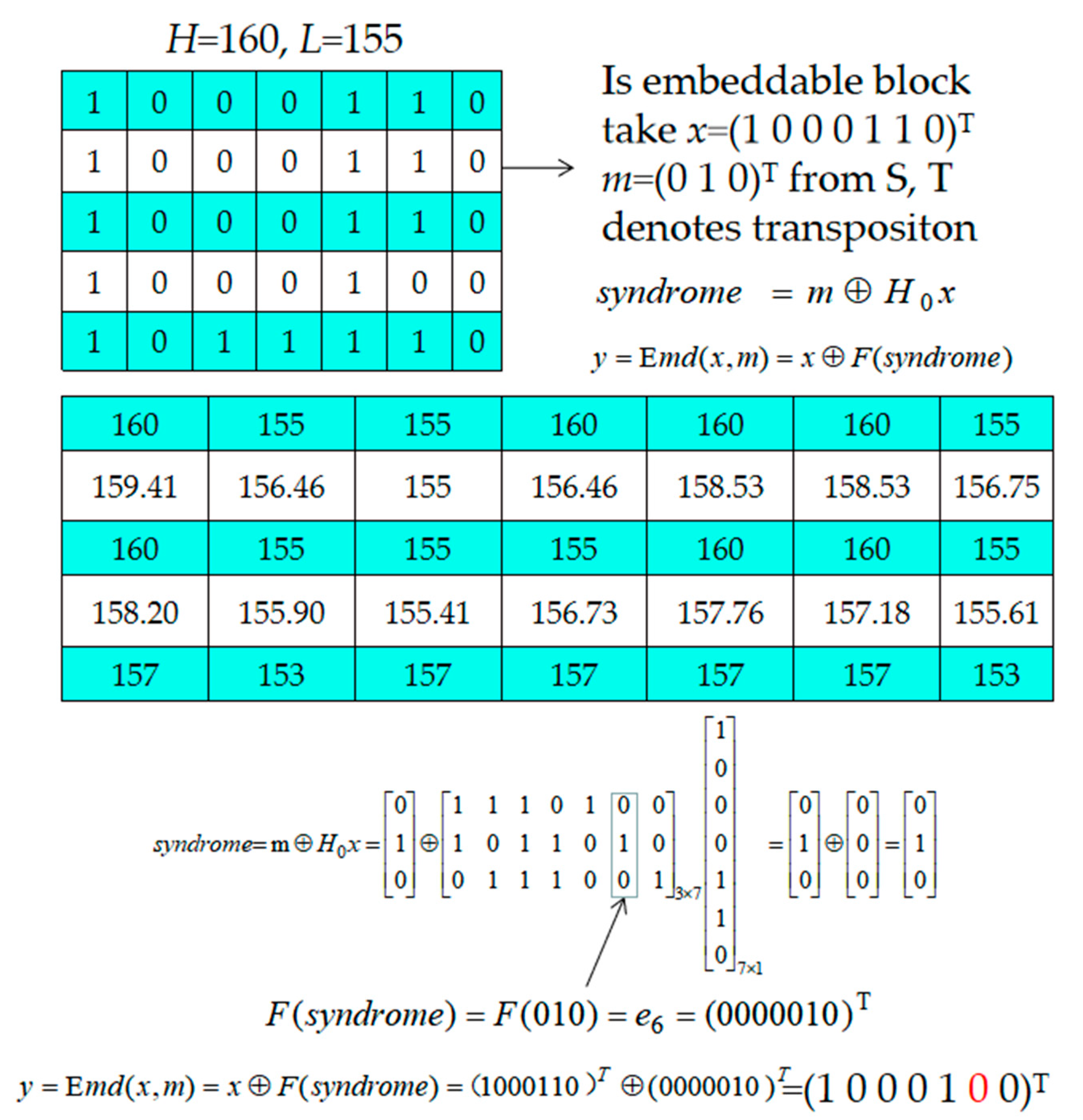
  • Step 5. After all H and L pairs have been checked, take three bits of the remaining S as m and embed them into block x, which is marked with “1” in the location map LP by using Equation (14). The detailed description can be referred to Section 2.2.
s y n d r o m e = m H 0 x and y = E m d ( x , m ) = x F ( s y n d r o m e ) ,
where y is the received stego vector, and F(·) is the value of the ith position of block x that must be changed.

Example of Data Embedding

Below, we have provided an example to show our hybrid hiding strategy. First, assume that there is a secret bitstream as S = 101 010 101 100 011 and an AMBTC-compressed trio (L = 155, H = 160, Bm = 10001101000110100011 010001001011110), as shown in Figure 6. The first two bits, i.e., “10”, listed in S indicate that the 1 × 7-sized block located in the second row is embeddable and that the 1 × 7-sized block located in the fourth row is unembeddable. The third bit “1” of S indicates that the order of L and H should be swapped according to hiding strategy depicted in Step 2. The following 3-bits “010” is then embedded into the 1 × 7 block located in the second row according to Equation (14). Since the block located in the second row is determined as embeddable and HL, seven bits of the corresponding bitmap are extracted as x = (1 0 0 0 1 1 0). Then, treat the 3-bit secret, “010”, as m and use parity cheek matrix, H0. Finally, x must be changed as y = (1 0 0 0 1 0 0) to carry the secret bits “010”. Finally, the modified AMBTC-compressed trios are obtained and then transmitted to the receiver.

3.3. Data Extraction and Recovery Phase

In data extraction phase, the receiver can perform data extraction with the received AMBTC-compressed trios, ( H , L , B m n × 7 ) i , j , where ( i , j ) is the coordinate of the n × 7 pixel block, i = 1, 2, …, 128, and j = 1, 2, …, 73. The parity cheek matrix, H0, which is like a password, can be used several times as long as it is transmitted via a secure channel. Generally, the receiver is aware of the hidden data based on the order of L and H. From the extracted data from the L and H, location map LP can be derived to indicate which 1 × 7 blocks are embeddable. Finally, not only the secret data are extracted but also the original AMBTC-compressed trios can be obtained. The detailed data extraction procedure is shown below.
Input: The stego bitstream with ( H , L , B m n × 7 ) i , j and the parity check matrix H0.
Output: The original secret message and the reconstructed AMBTC compressed image.
  • Step 1. Scan stego bitstream ( H , L , B m n × 7 ) i , j , and if H = L, extract 1 × 7 secret bits from the Bm. If H > L, extract secret bit “0”; otherwise, extract secret bit “1”, and swap H and L.
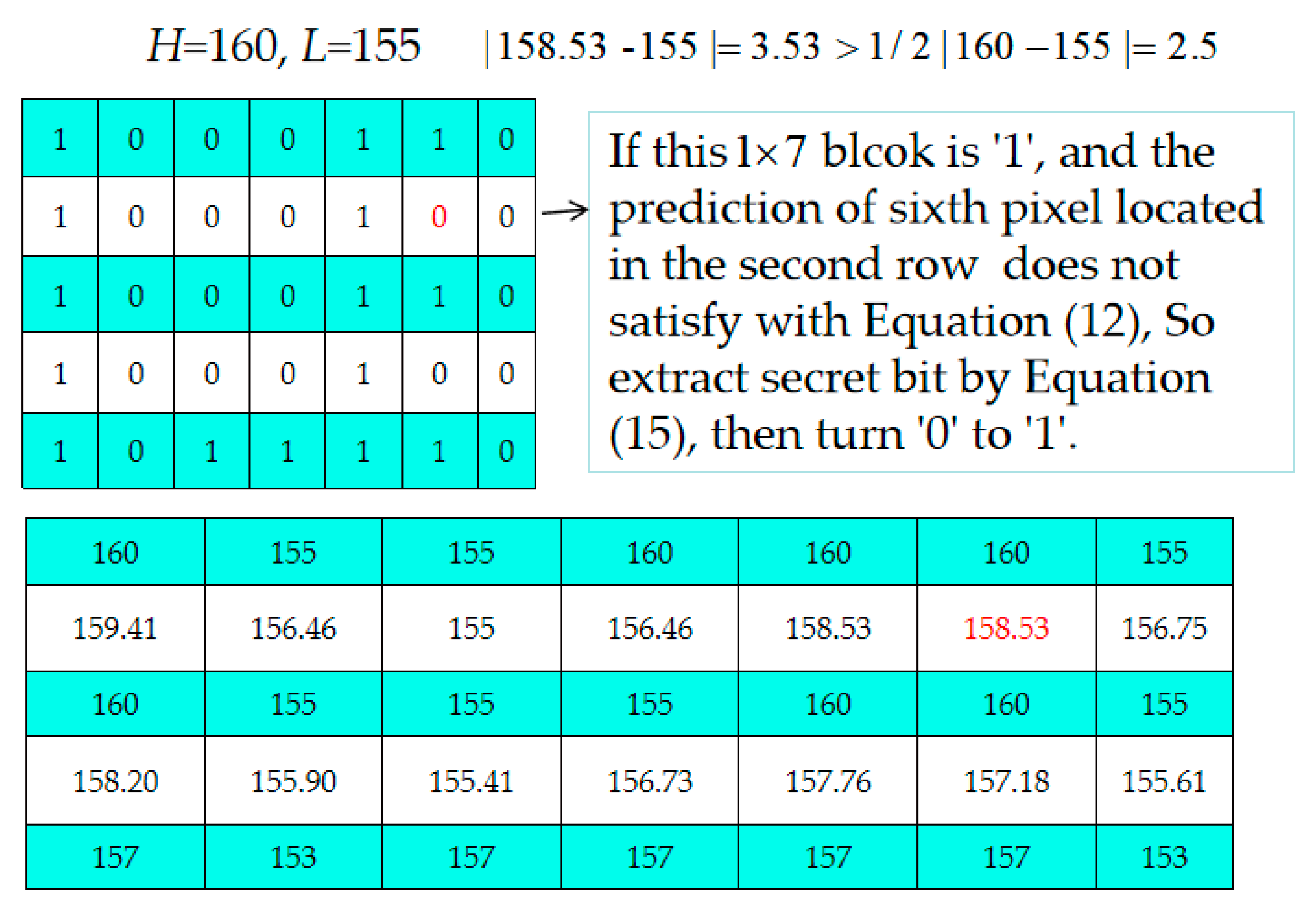
  • Step 2. Decide which 1 × 7-sized blocks located in even rows are embeddable or not according to the extracted location map, LP. If the current block is an embeddable block, 3 bits are extracted from the corresponding 1 × 7 bits of Bm according to Equation (15) [34].
    m = H 0 y
    If the current block is unembeddable, go to Step 4.
  • Step 3. Use Equation (12) to check each pixel of the embeddable block to see it is satisfied. If one pixel is not satisfied, modify its bit value to its complementary bit value, i.e., if the current bit value is “0”, change it to “1” and vice versa.
  • Step 4. Check the next embeddable block until all blocks are preceded. Output all extracted secret data and replace the corrected bitmaps with the corresponding Hs and Ls to obtain the reconstructed AMBTC-image.

Example of the Data Extraction and Recovery Phase

As shown in Figure 7, we demonstrate our proposed data extraction and recovery operation in this subsection. Here, we skip the data extraction and recovery operations for extracting the hidden data of the two quantizers and restoring the order of L and H. In this example, we focus only on how to extract the hidden data from the 1 × 7-sized block of Bm and restore the modified bit value. Based on the extracted location map, LP, the blocks of which are located in the even blocks can be easily to be identified. Therefore, the receiver knows which 1 × 7-sized block located in the second row is embeddable and which 1 × 7-sized block located in the second row should be treated as unembeddable. However, for the sixth pixel located in the second row, its prediction pixel value is 158.53 according to Equation (9), and the following equation does not hold. Such a situation is not consistent with the rule for the selection of an embeddable block as defined in Equation (12).
| 158.53 155 | > 1 / 2 | 160 155 | .
Therefore, we can conclude that the sixth pixel marked in red should be changed from “0” to “1.” With our designed justified rule, the original 1 × 7-sized bitmap is guaranteed to be restored.

4. Experimental Results

In this section, we describe the series of experiments and analyses that were performed to demonstrate the performance of the proposed scheme. All of the experiments were implemented in MATLAB R2014b on a PC with Intel® Core (TM) i7-8750H CPU @2.20 GHz, 16 GB RAM. The eight classic grayscale images, shown in Figure 8, with sizes of 512 × 512, i.e., Lena, Airplane, Barbara, Goldhill, Wine, Bird, Zelda, and Boat, were selected from the USC-SIPI data [35] and served as the test images. All of the test images were compressed using the AMBTC compression technique with the size of 2 × 7 and 4 × 7 pixels, respectively.
P S N R = 10 log 10 ( 255 2 M S E ) ( dB ) ,
M S E = i = 1 H T j = 1 W H ( x i , j x i , j ) 2 / ( H T × W H ) ,
We defined Type I as the stego codes that can be correctly decoded via a standard BTC or AMBTC decoder [27]. In this section, we performed 2 × 7 and 4 × 7 experiments to demonstrate the performance of the proposed scheme and to compare the results with other related type I works, including the work of Chen et al. [23]. In Chen et al.’s scheme, the relationship of H and L was used to embed the secret bits.
In the first experiment, the peak signal-to-noise ratio (PSNR) was used to estimate the visual quality of the AMBTC-compressed image, which is defined in Equation (16), where the mean-square-error (MSE) is shown in Equation (17) and where x i , j and x i , j indicate the pixel values for the position (i, j) of the original image and of the AMBTC-compressed image or steganography image, respectively. HT and WH represent the height and width of an image, respectively.
To examine the occurrence of secret bits in the stego bitstream codes, we used the embedding efficient rate (ER), which was calculated by Equation (18) It is noted the stego bitstream codes mentioned in this section is the stego AMBTC compression codes generated by our proposed scheme.
E R = H C C S
Both HC and CS are the total secret bits embedded and the size of the stego bitstream codes, respectively. An embedding method with higher efficiency indicated that our proposed RDH scheme offers a larger payload for the same size of stego bitstream codes.
In our proposed RDH scheme, when L = H, no secret bits can be embedded into two quantizers L and H by swapping the order of L and H. In addition, no secret bits can be embedded into the 1 × 7 blocks located in the even rows. Table 1 indicates that there is no such scenario for “Lena,” “Barbara,” “Zelda,” and “Boat”, irrespective of whether the partition strategy was set as 2 × 7 or 4 × 7. For “Airplane” and “Bird,” there was a single block the two quantizers of which were the same when the partition strategy was set as 2 × 7 By contrast, there are 398 blocks and 89 blocks which can be used for swapping the order of L and H to carry secret data in the “Wine” image.
Table 2 shows the embaddable blocks in eight test images for 2 × 7 partition. The total number of blocks is 512 × 511/2/7 = 18,688. The average number of embeddable blocks is 3,869, and the average of ratio is 0.208. The number of blocks with one bit changed and the number of blocks without bits changed are also shown in Table 2. In other words, our designed prediction mechanism which is defined in data embedding phase and justify mechanism defined in data extraction and recovery phase is required.
When Table 3 and Table 4 were compared, it was obvious that the total hiding capacity with the 2 × 7 partition was larger than that with the 4 × 7 partitions in our proposed scheme. The comparison of the different partition indicated that the PSNR and HLC and THC, IC are reduced when the partition size becomes larger. It is noted that the PSNR the computed from the stego compression codes generated by our proposed scheme and the original image. Because our proposed scheme is reversible data hiding scheme, the original AMBTC compression codes can be completely restored. In other words, the PSNR of our proposed scheme after extraction the hidden data will be the same as those listed in the first column in Table 4. Basically, there is no fixed rule between HC and EHC. In general, the more complex the image is, the less its embedding capacity is. As Table 1 indicates that only “Wine” has the largest hiding capacity in the 4 × 7 and 2 × 7 partitions when H = L. Although the effective hiding capacity (EHC) in the 2 × 7 case is less than that in the 4 × 7 partition for bitmap embedding, it offers more quantizer pairs to carry secret data. Therefore, in general, the total hiding capacity is increased.
To further demonstrate the performance of our proposed RDH scheme, we compared it with the conventional AMBTC and with Chen et al.’s scheme [23], which is presented in Table 5. It is noted that the PSNR listed in Chen et al.’s scheme is demonstrated the PSNR.
Compared with Chen et al.’s scheme, which only embeds one-bit of secret data into a pair of quantization values by swapping them when two quantizers are not the same. Therefore, the sizes of the compression codes of the two schemes were the same. Therefore, the ER of our proposed RDH scheme for the 2 × 7 partition was higher than that of Chen et al.’s scheme. In general, the hiding capacity of our proposed RDH scheme for the 2 × 7 partition was higher than that of Chen et al.’s scheme at the cost of slightly less quality of the images than conventional AMBTC and Chen et al.’s scheme. This is because our proposed RDH scheme embeds both secret data and bitmaps into the quantizer pairs. Even the image quality of the stego compression codes with our proposed scheme is slightly less than that of Chen et al.’s scheme [23]. It is noted that both of our schemes are reversible data hiding. In other words, the original AMBTC compression codes are always completely restored after the extraction of the hidden data. The size of the stego compression codes is always the same as that of Chen et al.’s scheme [23] and the original AMBTC compression codes. Therefore, no matter from the size and structure of stego compression codes, our stego compression codes would not attract attackers’ attention even the size of hidden data is larger than that of Chen et al.’s scheme [23].
To further prove the performance of our proposed RDH scheme on visual quality and hiding capacity outperforms other schemes, the comparisons of our proposed RDH scheme and five representative BTC/AMBTC-based RDH schemes are presented in Table 6.
From Table 6, we can see BTC/AMBTC-based RDH schemes [26,27,28] usually offer high hiding capacity at the cost of their stego-compression codes cannot be correctly decoded by the conventional BTC/AMBTC decoders. In other words, attackers can guess there is valuable information has been hidden out there. It could make the hidden conventional data insecure. By contrast, our proposed RDH scheme belongs to Type I AMBTC-based RDH scheme, and the stego-compression codes can be always decoded by the conventional AMBTC decoder. That means the stgo-compression codes could not attract malicious attackers’ attention and the security of hidden data is better than that of RDH schemes which belong to Type II BTC/AMBTC-based RDH schemes [26,27,28]. To make sure the stego-compression codes is decodable by conventional AMBTC decoder; the hiding capacity is relatively limited. However, from Table 6, we can see the hiding capacity of our proposed RDH scheme is only less than that of schemes of Sun et al. [26] and Hong et al. [27]. As for Lin et al.’s scheme [28], even their hiding capacity is significantly higher than ours, their scheme is Type II and they hided secret data into spatial domain of image by referring the features derived from AMBTC. In other words, they did not conceal secret data into structure of AMBTC compression codes but into the pixels of images. However, their scheme still points out the other possible direction which we shall explore and set as our research topic in the future.

5. Discussion and Conclusions

In this paper, we proposed RDH based on AMBTC with (7,4) hamming code. We embedded secret bits into the relationship of HL and into the bitmap. Before embedding the secret bits, we determined which blocks were embeddable, and we embedded the secret bits into this embeddable block with (7,4) hamming code. Compared with Type I AMBTC-based RDH scheme, experimental results confirm that our proposed RDH scheme has its merit in the capacity of the bitmap. Moreover, the hiding capacity offered by our proposed RDH scheme is significantly higher than that of schemes of Chen et al. [23], Lo et al. [24], and Chang et al. [25]. However, we also found even our proposed RDH scheme has enhanced the hiding capacity than other existing Type I BTC/AMBTC-based RDH schemes, but it is still less than that of Type II BTC/AMBTC-based RDH schemes. It will be our next research topic to allow our proposed RDH scheme to be supportive for various applications while maintaining security of the hidden data. Moreover, the data hiding method based on neural networks [36] and other methods [37,38,39,40,41] will be included to improve the hiding capacity in the future.

Author Contributions

C.-C.C. conceived the overall idea of the article. J.L. carried out the experiments and analyzed the data. C.-C.L. wrote the paper.

Funding

This work was supported in part by the Natural Science Foundation of Fujian Province of China under Grant 2018J01788, 2015J05146.

Conflicts of Interest

The authors declare no conflict of interest.

References

  1. Hong, W.; Chen, T.S.; Chen, J. Reversible data hiding using delaunay triangulation and selective embedment. Inf. Sci. 2015, 308, 140–154. [Google Scholar] [CrossRef]
  2. Zielinska, E.; Mazurczyk, W.; Szczpiorski, K. Trends in steganography. Commun. ACM 2014, 57, 86–95. [Google Scholar] [CrossRef]
  3. Barton, J.M. Method and Apparatus for Embedding Authentication Information with Digital Data. U.S. Patent 5646997, 8 July 1997. [Google Scholar]
  4. Tian, J. Reversible data embedding using a difference expansion. IEEE Trans. Circuits Syst. Video Technol. 2003, 13, 890–896. [Google Scholar] [CrossRef] [Green Version]
  5. Li, X.; Zhang, W.; Gui, X.; Yang, B. A novel reversible data hiding scheme based on two-dimensional difference-histogram modification. IEEE Trans. Inf. Forensics Secur. 2013, 8, 1091–1100. [Google Scholar]
  6. Ni, Z.; Shi, Y.Q.; Ansari, N.; Su, W. Reversible data hiding. IEEE Trans. Circuits Syst. Video Technol. 2006, 16, 354–362. [Google Scholar]
  7. Lin, C.C.; Tai, W.L.; Chang, C.C. Multilevel reversible data hiding based on histogram modification of difference images. Pattern Recognit. 2008, 41, 3582–3591. [Google Scholar] [CrossRef]
  8. Wang, W.; Ye, J.; Wang, T. A high capacity reversible data hiding scheme based on right-left shift. Signal Process. 2018, 150, 1129–1143. [Google Scholar] [CrossRef]
  9. Li, X.; Yang, B.; Zeng, T. Efficient reversible watermarking based on adaptive predirection-error expansion and pixel selection. IEEE Trans. Image Process. 2011, 20, 1061–1070. [Google Scholar]
  10. Li, X.; Zhang, W.; Gui, X.; Yang, B. Efficient reversible data based on multiple histograms modification. IEEE Trans Inf. Forensics Secur. 2015, 10, 2016–2027. [Google Scholar]
  11. Xiao, M.; Li, X.L.; Wang, Y.Y.; Zhao, Y.; Ni, R.R. Reversible data hiding based on pairwise embedding and optimal expansion path. Signal Process. 2019, 158, 210–218. [Google Scholar] [CrossRef]
  12. Ahmed, N.; Natarajan, T.; Rao, K. Discrete cosine transform. IEEE Trans. Comput. 1974, C-23, 90–93. [Google Scholar] [CrossRef]
  13. Haar, A. Discrete cosine transform. Math. Ann. 1911, 71, 38–53. [Google Scholar] [CrossRef]
  14. Gray, R. Vector quantization. IEEE ASSP Mag. 1984, 1, 4–29. [Google Scholar] [CrossRef]
  15. Kim, T. Side match and overlap match vector quantizers for images. IEEE Trans. Image Process. 1992, 1, 170–185. [Google Scholar] [CrossRef]
  16. Yang, B.; Lu, Z.; Sun, S. Reversible watermarking in the VQ-compressed domain. In Proceedings of the 5th IASTED International Conference on Visualization, Imaging, and Image Processing, Benidorm, Spain, 7–9 September 2005; pp. 273–275. [Google Scholar]
  17. Lu, Z.; Wang, J.; Liu, B. An improved lossless data hiding scheme based on image VQ-index residual value coding. J. Syst. Softw. 2009, 82, 1016–1024. [Google Scholar] [CrossRef]
  18. Chang, C.C.; Tai, W.L.; Lin, C.C. A reversible data hiding scheme based on side match vector quantization. IEEE Trans. Circuits Syst. Video Technol. 2006, 16, 1301–1308. [Google Scholar] [CrossRef]
  19. Chiou, S.F.; Liao, I.E.; Hwang, M.S. A capacity-enhanced reversible data hiding scheme based on SMVQ. Imaging Sci. J. 2011, 59, 17–24. [Google Scholar] [CrossRef]
  20. Delp, E.J.; Mitchell, O.R. Image compression using block truncation coding. IEEE Trans. Commun. 1979, 27, 1335–1342. [Google Scholar] [CrossRef]
  21. Rover Camera Instrument Description. Available online: https://pdsimg.jpl.nasa.gov/data/mpfr-m-rvrcam-2-edr-v1.0/mprv_0001/document/rcinst.htm (accessed on 9 November 2011).
  22. Lema, M.; Mitchell, O.R. Absolute moment block truncation coding and its application to color images. IEEE Trans. Commun. 1984, 19, 1148–1157. [Google Scholar] [CrossRef]
  23. Chen, J.; Hong, W.; Chen, T.S.; Shiu, C.W. Steganography for BTC compressed image using no distortion technique. Imaging Sci. J. 2010, 58, 177–185. [Google Scholar] [CrossRef]
  24. Lo, C.C.; Hu, Y.C.; Chen, W.L.; Wu, C.M. Reversible data hiding scheme for BTC-compressed images based on histogram shifting. Int. J. Secur. Appl. 2014, 8, 301–314. [Google Scholar] [CrossRef]
  25. Chang, I.C.; Hu, Y.C.; Chen, W.L.; Lo, C.C. High capacity reversible data hiding scheme based on residual histogram shifting for block truncation coding. Signal Process. 2015, 108, 376–388. [Google Scholar] [CrossRef]
  26. Sun, W.; Lu, Z.M.; Wen, Y.C.; Yu, F.X.; Shen, R.J. High performance reversible data hiding for block truncation coding compressed image. SIViP 2013, 7, 297–306. [Google Scholar] [CrossRef]
  27. Hong, W.; Ma, Y.B.; Wu, H.C.; Chen, T.S. An efficient reversible data hiding method for AMBTC compressed images. Multimed. Tools Appl. 2017, 76, 5441–5460. [Google Scholar] [CrossRef]
  28. Lin, C.C.; Chang, C.C.; Wang, Z.M. Reversible Data hiding scheme using adaptive block truncation coding based on an edge-based quantization approach. Symmetry 2019, 11, 765. [Google Scholar] [CrossRef]
  29. Chang, C.C.; Kieu, T.D.; Chou, Y.A. high payload steganographic scheme based on (7,4) hamming code for digital images. In Proceedings of the 2008 International Symposium on Electronic Commerce and Security, Guangzhou, China, 3–5 August 2008; pp. 16–21. [Google Scholar] [CrossRef]
  30. Cao, Z.; Yin, Z.; Hu, H.; Gao, X.; Wang, L. High capacity data hiding scheme based on (7,4) hamming code. Springer Plus 2016, 5, 1–13. [Google Scholar] [CrossRef]
  31. Bai, J.; Chang, C.C. A high payload steganographic scheme for compressed images with hamming code. Int. J. Netw. Secur. 2016, 18, 1122–1129. [Google Scholar]
  32. Biswapati, J.; Giri, D.; Mondal, S.K. Partial reversible data hiding scheme using (7,4) hamming code. Multimed. Tool Appl. 2017, 76, 21691–21706. [Google Scholar]
  33. Biswapati, J.; Giri, D.; Mondal, S.K. Dual image based reversible data hiding scheme using (7,4) hamming code. Multimed. Tool Appl. 2018, 77, 763–785. [Google Scholar]
  34. Mao, Q. A fast algorithm for matrix embedding steganography. Digit. Signal Process. 2014, 25, 248–254. [Google Scholar] [CrossRef]
  35. The USC-SIPI Image Database. Available online: http://sipi.usc.edu/database (accessed on 9 November 1977).
  36. Luigi, F.; Paolo, A.; David, B.; Ákos, Z. Cellular neural networks: A paradigm for nonlinear spatio-temporal processing. IEEE Circuits Syst. Mag. 2001, 1, 6–21. [Google Scholar]
  37. Zhong, H.; Chen, X.; Tian, Q. An Improved Reversible Image Transformation Using K-Means Clustering and Block Patching. Information 2019, 10, 17. [Google Scholar] [CrossRef]
  38. Hu, Y.C.; Lin, Y.H.; Lo, Y.H.; Lo, C.C.; Wu, C.M. Implementation of Block-Based Hierarchical Prediction for Developing an Error-Propagation-Free Reversible Data Hiding Scheme. Symmetry 2019, 11, 1146. [Google Scholar] [CrossRef]
  39. Leng, H.S. Generalized Scheme Based on Octagon-Shaped Shell for Data Hiding in Steganographic Applications. Symmetry 2019, 11, 760. [Google Scholar] [CrossRef]
  40. Chen, K.M.; Chang, C.C. Real-Time Error-Free Reversible Data Hiding in Encrypted Images Using (7,4) Hamming Code and Most Significant Bit Prediction. Symmetry 2019, 11, 51. [Google Scholar] [CrossRef]
  41. Hou, X.; Min, L.Q.; Yang, H. A Reversible Watermarking Scheme for Vector Maps Based on Multilevel Histogram Modification. Symmetry 2018, 10, 397. [Google Scholar] [CrossRef]
Figure 1. Example of the absolute moment block truncation coding (AMBTC) compression method: (a) Original image block; (b)AMBTC bitmap; (c) Reconstructed image block.
Symmetry 11 01236 g001
Figure 2. Reconstructed Yi and its neighboring six reconstructed pixels.
Symmetry 11 01236 g002
Figure 3. Coefficients of the six neighboring pixels of Y i .
Symmetry 11 01236 g003
Figure 4. Example of the selection of embeddable blocks: (a) Example of 5 × 7 reconstructed pixels of Figure 1a; (b) The sixth prediction value located in the fourth row is derived as by Equation (9). The sixth pixel located in the fourth row does not satisfy with Equation (12).
Symmetry 11 01236 g004
Figure 5. Flowchart of the embedding phase.
Symmetry 11 01236 g005
Figure 6. Example of data embedding phase.
Symmetry 11 01236 g006
Figure 7. Example of the data extraction and recovery phase.
Symmetry 11 01236 g007
Figure 8. Eight test images
Symmetry 11 01236 g008
Table 1. Amount blocks in which the high mean was equal to the low mean for 2 × 7 and 4 × 7 partition strategies.
ImageLanaAirplaneBarbaraGoldhillWineBirdZeldaBoat
2 × 70106398800
4 × 7000189000
Table 2. Embeddable blocks in eight test images for 2 × 7 partition.
ImageLanaAirplaneBarbaraGoldhillWineBirdZeldaBoat
Number of embeddable blocks39803482392430375314367643863155
Number of blocks with one bit changed36143134355626865060333240062821
Number of blocks without bits changed366348368351254344380334
Ratio 10.210.190.210.160.290.200.240.17
1 Where Ratio = number of embeddable blocks/total number of odd blocks.
Table 3. Peak signal-to-noise ratios (PSNRs) and hiding capacity (HC) of our proposed reversible data hiding (RDH) scheme for the 2 × 7partition.
2 × 7
(18,688)
Criteria
AMBTC
PSNR
(dB)
PSNR
(dB)
H ≠ L
HC
(bits)
Proposed Scheme
H ≠ L
IC
(bits)
H ≠ L
EHC
(bits)
H = L
HLC
(bits)
Total of HC 1
(bits)
Lena32.0529.8811,94086123328022,016
Airplane31.929.1710,446795324931421,194
Barbara28.927.6611,77282663506022,194
Goldhill32.5231.079111702020918420,857
Wine32.0229.915,94210,4565486557229,348
Bird29.5728.311,0288821220711220,999
Zelda35.6733.9613,15897943364022,052
Boat30.7228.73946570962369021,057
Average31.6629.8311,6078502310572022,464
1 Here HC is the data embedding capacity in the bitmap with the (7,4) hamming code. IC is the number of remarks concerning which the block is “1” or “0.” EHC is the effective hiding capacity, where EHC = HCIC. HLC is the data embedding capacity, when H = L, and THC is the total data hiding capacity, where THC = EHC, THC = EHC + HLC + (18688-HLC/14).
Table 4. PSNRs and hiding capacity (HC) of our proposed RDH scheme for the 4 × 7 partition.
2 × 7
(9344)
Criteria
AMBTC
PSNR
(dB)
PSNR
(dB)
H ≠ L
HC
(bits)
Proposed Scheme
H ≠ L
IC
(bits)
H ≠ L
EHC
(bits)
H = L
HLC
(bits)
Total of HC 1
(bits)
Lena31.2929.4511,90789023005012,349
Airplane30.4928.2112,15988733286012,630
Barbara28.2527.1712,10285533549012,893
Goldhill31.3530.0311,286806332232812,594
Wine30.8429.0217,51111,2806231249217,978
Bird28.4627.4311,68593522333011,677
Zelda34.6633.2513,44010,2233217012,561
Boat29.6027.9910,98380372946012,290
Average30.6129.0612,6349160347431513,121
1 Here HC is the data embedding capacity in the bitmap with the (7,4) hamming code. IC is the number of remarks concerning which the block is “1” or “0.” EHC is the effective hiding capacity, where EHC = HCIC. HLC is the data embedding capacity, when H = L, and THC is the total data hiding capacity, where THC = EHC + HLC + (9344-HLC/28).
Table 5. Comparisons of the performances of the proposed scheme and Chen et al.’s scheme.
PerformanceSchemeLenaAirplaneBarbaraGoldhillWineBirdZeldaBoat
PSNRAMBTC32.0531.928.932.5232.0229.5735.6730.72
Chen [23]32.0531.928.932.5232.0229.5735.6730.72
Proposed29.8829.1727.6631.0729.928.333.9628.73
HCChen [23]18,68818,70118,68818,76623,86418,68818,68818,792
Proposed22,01621,19422,19420,85729,34820,99922,05221,057
CS1Chen [23]564,736564,736564,736564,736564,736564,736564,736564,736
Proposed564,736564,736564,736564,736564,736564,736564,736564,736
ERChen [23]0.0330.0330.0330.0330.0420.0330.0330.033
Proposed0.0390.0380.0390.0370.0520.0370.0390.037
1 Note: CS is the size of the, ER = HC/CS.
Table 6. Comparisons of the performances of the proposed scheme and five representative block truncation coding (BTC)/AMBTC-based RDH schemes.
SchemesTypesAverage PSNRsmax PSNR/
min PSNR
Average HCmax HC/
min HC
Average ERmax ER/
min ER
ProposedI(code)29.8333.96/27.6622,46429,348/20,9990.040.052/0.037
Chen et al. [23]I(code)32.2835.67/28.9019,35923,864/18,6880.0370.042/0.033
Lo et al. [24]I(code)33.133.23/32.9736154570/26600.0060.008/0.005
Chang et al. [25]I(code)31.7432.89/30.5916,38112,683/20,0800.0310.024/0.038
Sun et al. [26]II(code)29.733.40/26.064,00864,008/64,0080.1220.122/0.122
Hong et al. [27]II(code)30.1933.39/26.9164,51664,516/64,5160.120.116/0.125
Lin et al. [28]II(code)33.3637.23/30.9190489114,533/70,8890.2400.241/0.217

