Article

An Efficient Data Transmission with GSM-MPAPM Modulation for an Indoor VLC System

1
School of Electronics and Electrical Engineering, Dong Guan Polytechnic, No. 3, University Road, Songshan Lake District, Dongguan 523808, Guangdong, China
2
Department of Electrical Engineering, St. John’s University, New Taipei City 25135, Taiwan
3
Department of Industrial Engineering and Management, St. John’s University, New Taipei City 25135, Taiwan
*
Author to whom correspondence should be addressed.
Symmetry 2019, 11(10), 1232; https://doi.org/10.3390/sym11101232
Submission received: 31 July 2019 / Revised: 11 September 2019 / Accepted: 16 September 2019 / Published: 2 October 2019
(This article belongs to the Special Issue Selected Papers from IIKII 2019 conferences in Symmetry)

Abstract

:
As an emerging wireless communication technique, visible light communication is experiencing a boom in the global communication field, and the dream of accessing to the Internet with light is fast becoming a reality. The objective of this study was to put forward an efficient and theoretical scheme that is based on generalized spatial modulation to reduce the bit error ratio in indoor short-distance visible light communication. The scheme was implemented while using two steps in parallel: (1) The multi-pulse amplitude and the position modulation signal were generated by combining multi-pulse amplitude modulation with multi-pulse position modulation using transmitted information, and (2) certain light-emitting diodes were activated by employing the idea of generalized spatial modulation to convey the generated multi-pulse amplitude and position modulation optical signals. Furthermore, pulse width modulation was introduced to achieve dimming control in order to improve anti-interference ability to the ambient light of the system. The two steps above involved the information theory of communication. An embedded hardware system, which was based on the C8051F330 microcomputer and included a transmitter and a receiver, was designed to verify the performance of this new scheme. Subsequently, the verifiability experiment was carried out. The results of this experiment demonstrated that the proposed theoretical scheme of transmission was feasible and could lower the bit error ratio (BER) in indoor short-distance visible light communication while guaranteeing indoor light quality.

1. Introduction

The white light-emitting diode (LED), which is known as the future star of green lighting, is replacing traditional lighting lamps and is widely used in indoor lighting applications. A promising characteristic of LEDs is their ability to rapidly flash on or off, which makes it possible to convey information; this is called visible light communication (VLC) and it is receiving global attention [1,2]. As VLC has advantages that traditional radio frequency (RF) communication lacks, it is considered to be a mutual enhancement to RF, especially for indoor applications. However, VLC also has flaws in its current development, such as the limitation of emission power using existing LEDs, which increases the bit error ratio (BER) and lowers the transmission rate of the system. Furthermore, using visible light to convey information is very susceptible to ambient light. Some solutions were proposed to address this, including the adoption of key technologies or algorithms in existing RF communication into the VLC system, so long as the structure or circuit involving the transmitter and receiver was slightly modified or upgraded.
One solution was to introduce effective modulations. In recent years, many modulations were put forward to achieve excellent communication and illumination performances regarding indoor VLC. In [3], multi-pulse position modulation (M-PPM), with the joint purpose of dimming and communication, was proposed to increase the spectrum efficiency and dimming control for VLC. In [4], an adaptive M-ary pulse amplitude modulation (M-PAM) for an indoor VLC system coordinated multiple LED lamps to provide users with the highest rate of data transmission. In [5], an optical spatial multiple pulse position modulation, which combined a high spectral efficiency space shift setting with high energy efficiency multiple pulse position modulation, was proposed to provide a balance between complexity, achievable spectral efficiency, and energy efficiency in an indoor VLC system. In [6], a VLC system that is based on the offset pulse position modulation (Offset-PPM) was demonstrated using a single commercial highpower white LED (30 W) and a new coding scheme; the results of this experiment showed that this modulation attained good performance regarding the BER within a certain distance. In [7], a multi-LED phaseshifted on-off keying (OOK) modulation was designed to overcome the two key challenges of the limited modulation bandwidth and the non-linearity nature of LEDs in VLC. In [8], an asymmetric frequency shift keying (FSK) modulation technique was proposed to mitigate flickering and dimming in square and rectified waves in a VLC system. In [9], an optical software-defined radio VLC system was introduced, with variable pulse position modulation being considered at the transmitter. This system attained a better data transmission rate through the simulation. In addition to the single carrier modulation above, many multi-carrier modulations were proposed. In [10], a DC-biased optical orthogonal frequency division multiplexing (DCO-OFDM) was used for optical wireless communication, which reduced the complexity of the conventional OFDM and improved the BER. However, the DCO-OFDM signal needed to be clipped at zero power and at peak power of the LED, which distorted the signal. In [11], an asymmetrically clipped optical OFDM (ACO-OFDM) was used to reduce the peak to average power ratio (PAPR) when only the odd subcarriers were modulated, resulting in low bandwidth utilization efficiency. The OFDM, which is a multi-carrier modulation, was very promising regarding its resistance to inter-symbol interference and its high spectral efficiency. However, due to the nonlinear response of the LED, when the OFDM was applied to the VLC, it caused a higher BER and PAPR than the single carrier modulation. Single carrier modulation might be a better alternative due to the requirements for the BER and PAPR in an indoor VLC system. Generally speaking, indoor LED lamps consist of multiple wicks, so the spatial dimension offered by these wicks to convey information can be utilized. Over the past 10 years, generalized spatial modulation (GSM) has received worldwide attention due to its better performance in the reduction of the BER than traditional spatial modulation [12,13].
The main objective of this paper was to put forward an efficient and theoretical scheme that is based on generalized spatial modulation with multi-pulse amplitude and position modulation (GSM-MPAPM) for an indoor VLC system to achieve a lower BER and pulse width modulation (PWM) dimming. This scheme was implemented on an embedded hardware system, which was based on the C8051F330 microcomputer.
The main contributions of this paper are as follows:
(1)
An efficient GSM-MPAPM modulation with PWM dimming for an indoor VLC system.
(2)
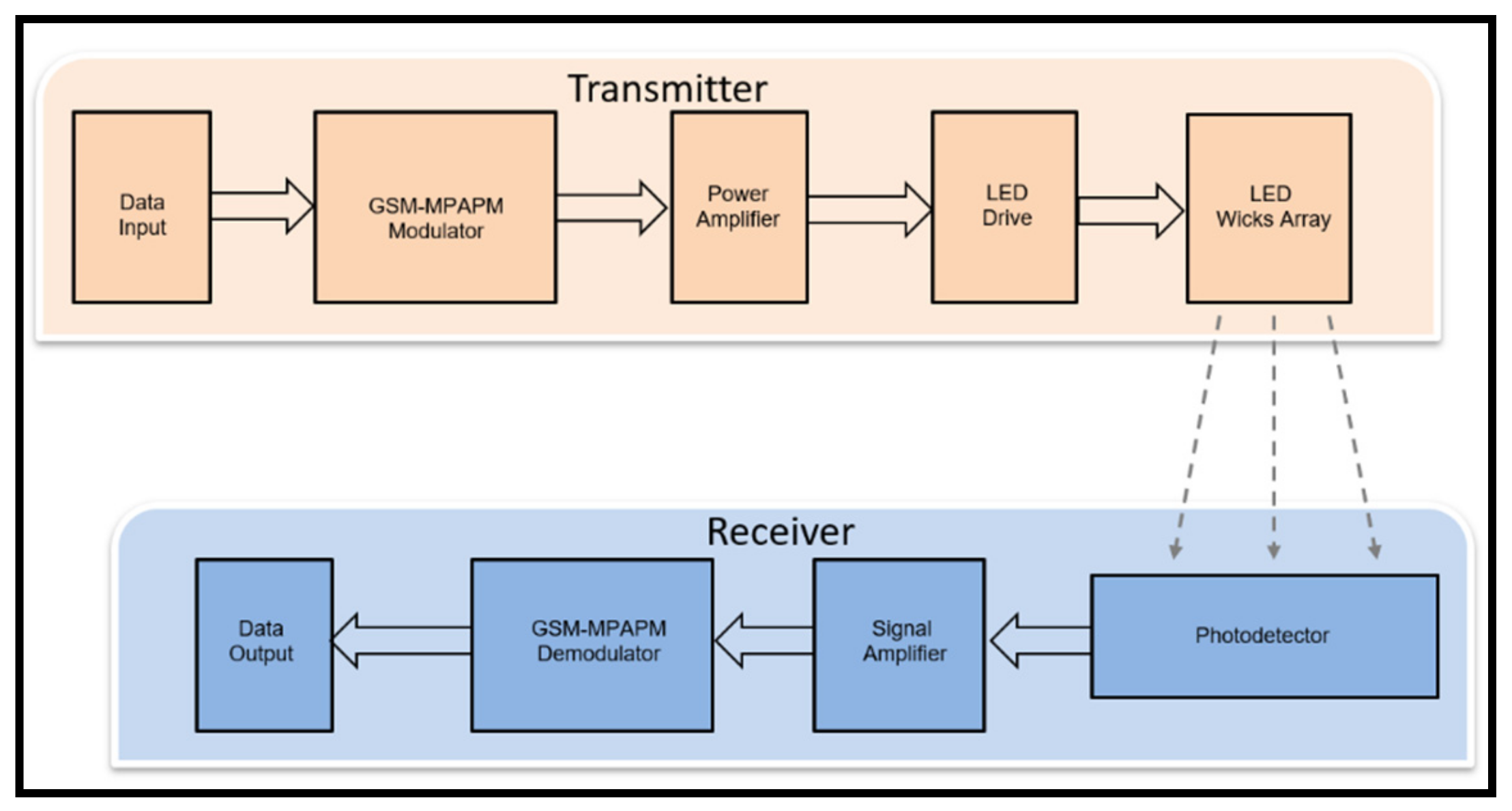
An embedded hardware system, including a transmitter and a receiver, which were both based on the C8051F330 microcomputer. The key innovation of this paper was to employ the idea of GSM to convey MPAPM optical signals. Moreover, an embedded hardware system was designed to achieve the theoretical scheme.
Firstly, theoretical and mathematical models for the VLC system were set up, which were mainly related to the information theory of communication. Secondly, the experiment was carried out with the help of computers and the embedded hardware that was designed for this purpose. This paper is organized, as follows. Section 2 presents related knowledge and the theory regarding MPAPM and GSM. Section 3 describes a typical VLC system and introduces the proposed modulation. Section 4 details the scheme implementation. Analysis of the experimental results is found in Section 5. Finally, the conclusions of this paper are summarized in Section 6.

2. Related Knowledge and Theory

2.1. MPAPM

The MPAPM is a compound modulation and it combines two basic modulations that are commonly employed in a VLC system, namely, MPPM and MPAM. For MPPM, the L continuous signals of the binary are modulated in a time period consisting of Q time-slots and optical pulses that appear in P time slots. Moreover, the P optical pulses are arranged according to a certain regularity, so it is generally recorded as (Q,P)MPPM. The relationship of Q, P, and L are expressed in Equation (1), where C Q P means the gain of MPPM [14].
C Q P = Q ! / P ! ( Q P ) ! 2 L
According to the definition of MPPM, it can be derived that the information that every symbol of MPPM can transmit is l o g 2 c Q P bits. Hence, the capability of the data transmission increases as the number of time-slots increases, which means that MPPM has a significant advantage regarding bandwidth utilization, as demonstrated in multiple analyses. MPPM is better than PPM in these two aspects.
For MPAM, all of the information is encoded into the amplitude of the signal; the amplitude of the transmitted signal takes M different values, which implies that each pulse conveys l o g 2 M bits per symbol time [15]. MPAM is superior to the other modulations when it comes to the data transmission rate and implementation complexity.
In this study, we designed a modulation method where the data transmission rate was the product of MPPM and MPAM, namely MPAPM. For analysis and comparison, it was expressed as (Q,P,M)MPAPM.

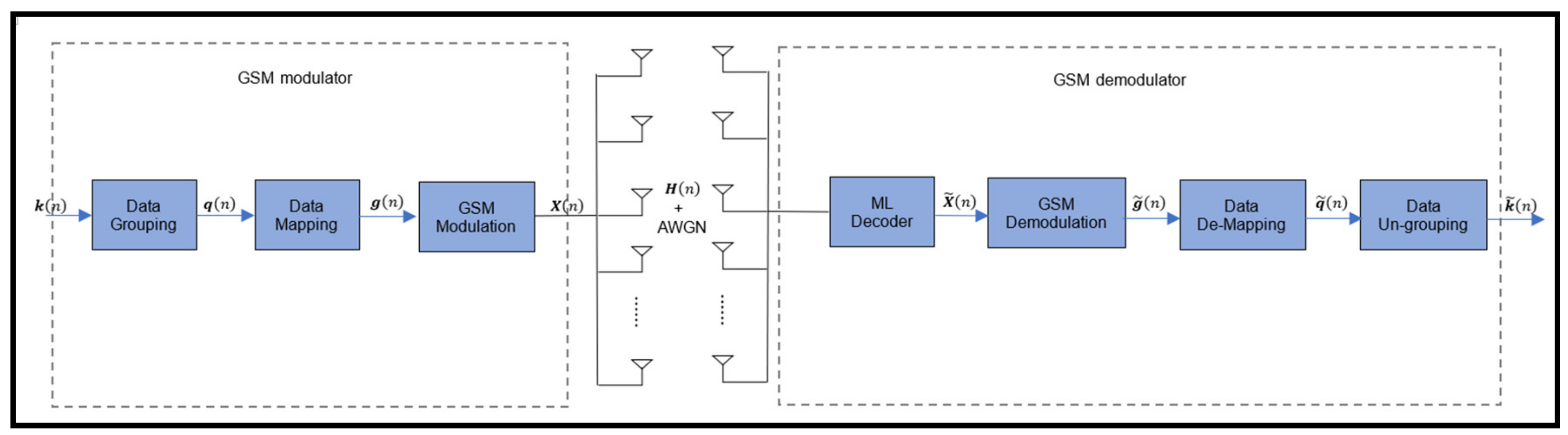
2.2. Generalized Spatial Modulation

As a special form of spatial modulation, GSM is receiving increased attention. Similarly to the multiple input and multiple output (MIMO) method, GSM activates multiple transmitting LEDs at the same time to simultaneously transmit the same information. The BER and the transmission rate both have thresholds because the number of LEDs cannot infinitely increase, which ultimately affects the performance of the system. However, unlike MIMO, GSM conveys transmitted information while using the activated combination of the transmitting LEDs, which are selected from a regular table. As a result, the number of transmitting LEDs required to achieve a certain spectral efficiency or BER is reduced as compared to MIMO. Transmitting the same information from more than one LED at a time not only retains the core advantage of MIMO, but also offers an increase in spatial diversity. Moreover, GSM completely avoids inter-carrier interference (ICI) at the receiver, which improves the reliability of the communication system [16,17]. Figure 1 depicts the GSM system model.
GSM employs multiple transmitting LEDs, which are activated to send the same information. Hence, a cluster of LEDs needs to be defined as the spatial constellation points. The combination number of LEDs is N = C N t N s , theoretically, where N t is the number of transmitting LEDs and N s is the number of LEDs activated at one time. However, the combination number of LEDs that can be considered for transmission must be a power of two, which removes doubles. Finally, the combination number is reduced to N x = 2 n , where n = l o g 2 C N t N s and is the floor operation.

3. The VLC System Based on GSM-MPAPM
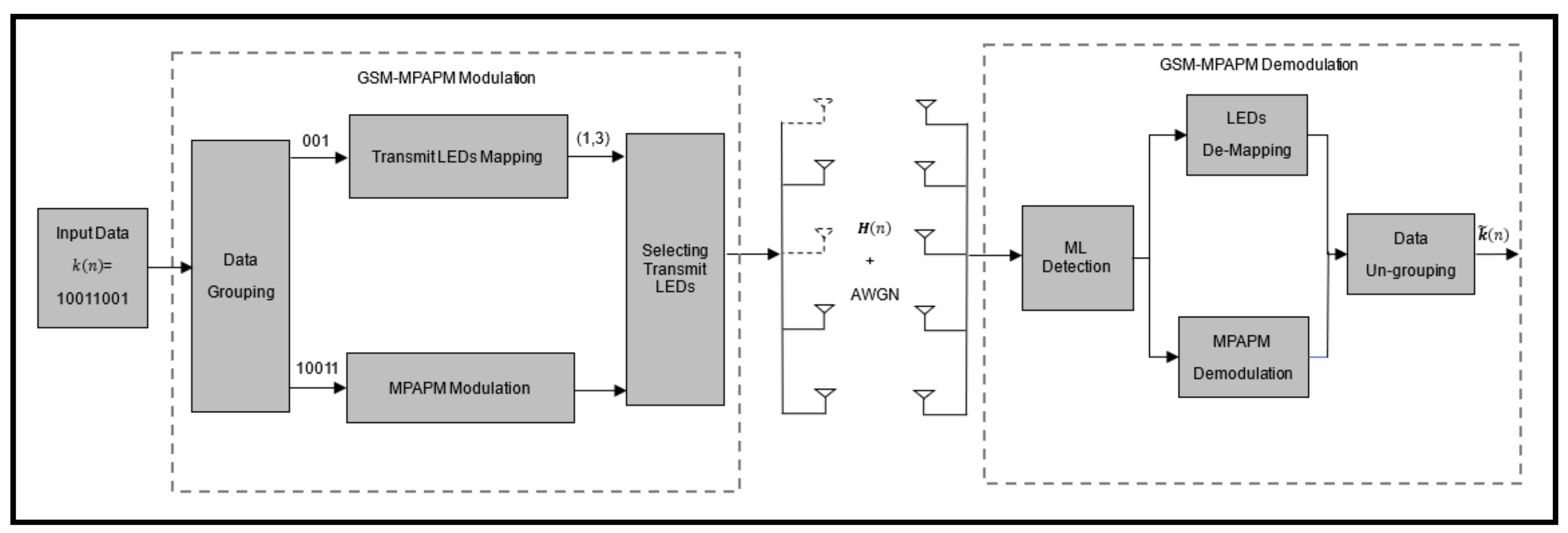
3.1. GSM-MPAPM

Figure 2 depicts the indoor VLC system model based on GSM-MPAPM; an example of the data mapping and transmission for every time slot is also shown. For simplicity, eight information bits are transmitted for every time slot. Hence, in every time slot, eight bits are first selected from the input data. Subsequently, they are divided into two groups, i.e., the group consisting of the combination of transmitting LEDs and the group consisting of the information bits. Finally, the two groups are separately mapped according to mapping tables. For simplicity, N t = 5 and N s = 2 are assumed. The mapping procedure modulates the first five bits while using MPAPM, and the remaining three bits are mapped according to the activated combination of LEDs.
The resultant combinations of the transmitting LEDs are listed in Table 1 and the MPAPM mapping rules are listed in Table 2. Table 1 shows that eight combinations of transmitting LEDs were obtained with the last three bits at one time. In Table 2, every time period is divided into 16 time slots, with the first four information bits are conveyed in one of the 16 time slots. The remaining bit is used to indicate the level of transmission power. Figure 3 shows the function of each bit in a time slot. For instance, if the eight information bits transmitted at one time are 10011001 , then five information bits are transmitted from LED 1 and LED 3 in time slot 10 with a transmission power of U 2 . In each time slot, the information bits are transmitted from the exiting five transmitting LEDs, while only two LEDs are activated at any given time. If MIMO is used instead of this modulation, the number of transmitting LEDs is increased to eight to maintain the same BER and spectral efficiency.

3.2. Information Bits Transmitted per Symbol

In Section 2, MPAPM modulation is expressed as (Q,P,M)MPAPM, where Q is the total number of time slots in a time period, P is the time slot that is used to convey the information bits, and M is the level number of amplitude. Therefore, in the proposed GSM-MPAPM, the information bits transmitted per symbol are represented by l o g 2 C Q P × M × C N t N s . GSM-MPAPM conveys more information bits per symbol and has a higher transmission rate when compared to the other modulations. Table 3 lists the information bits transmitted per symbol according to the different modulations.

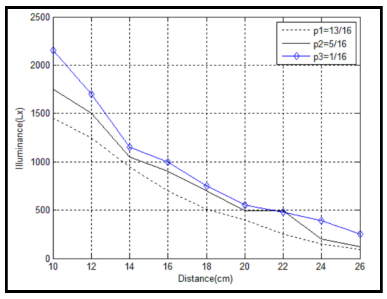
3.3. Dimming Strategy

In the proposed GSM-MPAPM, the dimming mechanism is implemented while using the principle that is presented in Table 4. The PWM dimming strategy is employed to change the intensity of LED illumination according to the duty cycle ratio of the pulse signals transmitted in time slot i. This is expressed as the differentiated dimming. In Table 4, pi (i = 1, 2, 3, 4) is the dimming coefficient, which has four different values throughout the 16 time slots. When p1 = 0.2, the information bits are conveyed in time slot 1, time slot 5, time slot 9, and time slot 13. When p2 = 0.4, the information bits are conveyed in time slot 2, time slot 6, time slot 10, and time slot 14. When p3 = 0.6, the information bits are conveyed in time slot 3, time slot 7, time slot 11, and time slot 15. When p4 = 0.8, the information bits are conveyed in time slot 4, time slot 8, time slot 12, and time slot 16. The dimming is implemented by choosing different coefficients. T represents a time period, including 16 time slots, while U represents the dimming voltage that is responsible for transmitting the information bits. In the actual system, if the dimming resolution of the PWM is k, the value increases four-fold in the innovative differentiated dimming. Undoubtedly, a more precise dimming is implemented with this strategy.

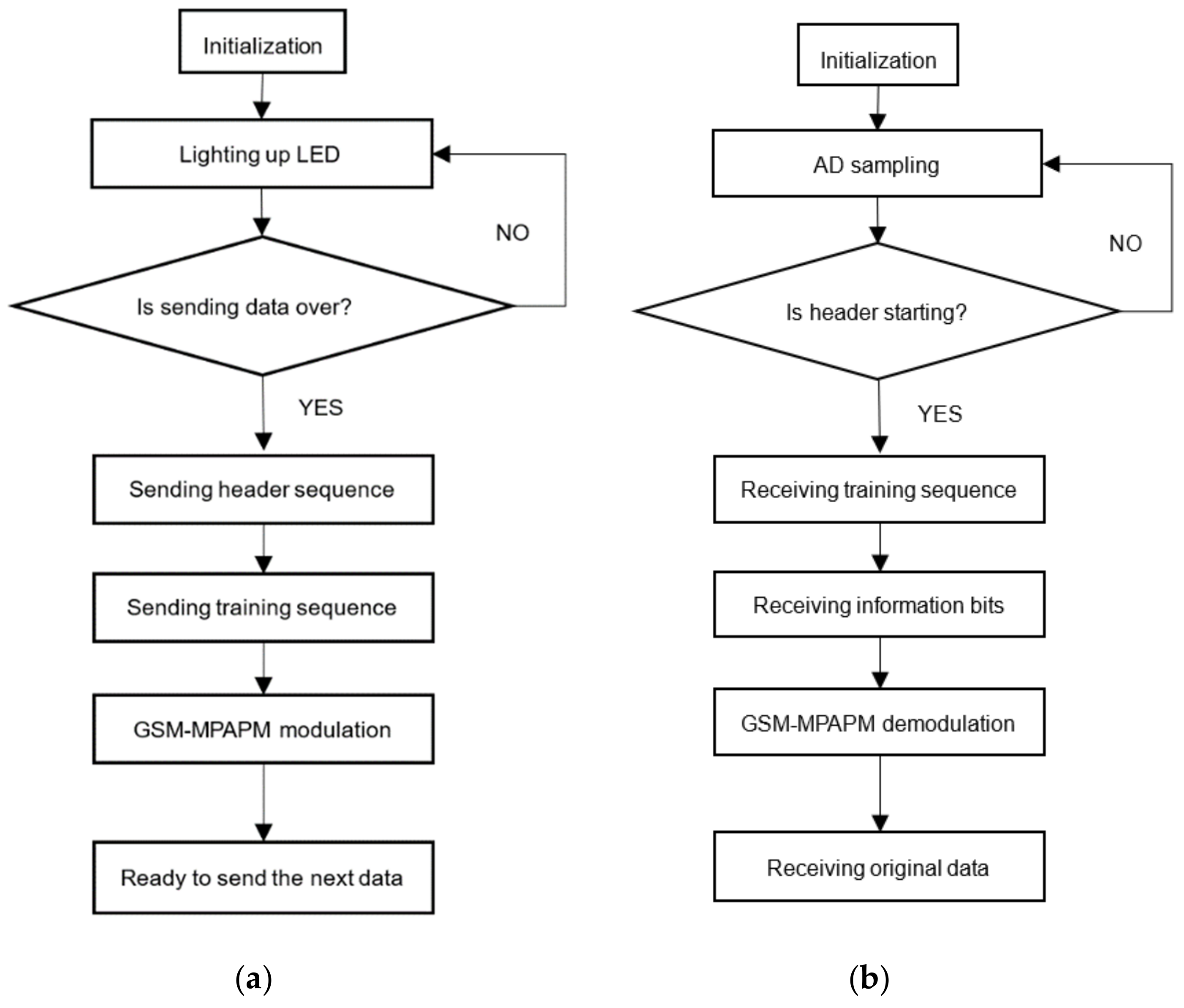
4. System Design and Implementation

An embedded hardware system was designed in order to test the performance of the proposed GSM-MPAPM in indoor VLC system. The overall system architecture includes two parts, the transmitter and the receiver. The optical signals of the information bits are conveyed in the free space. Figure 4 shows the overall VLC system architecture in detail.

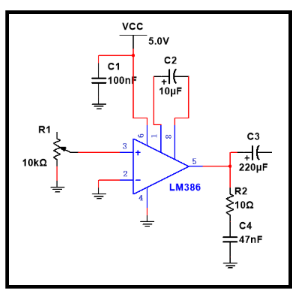
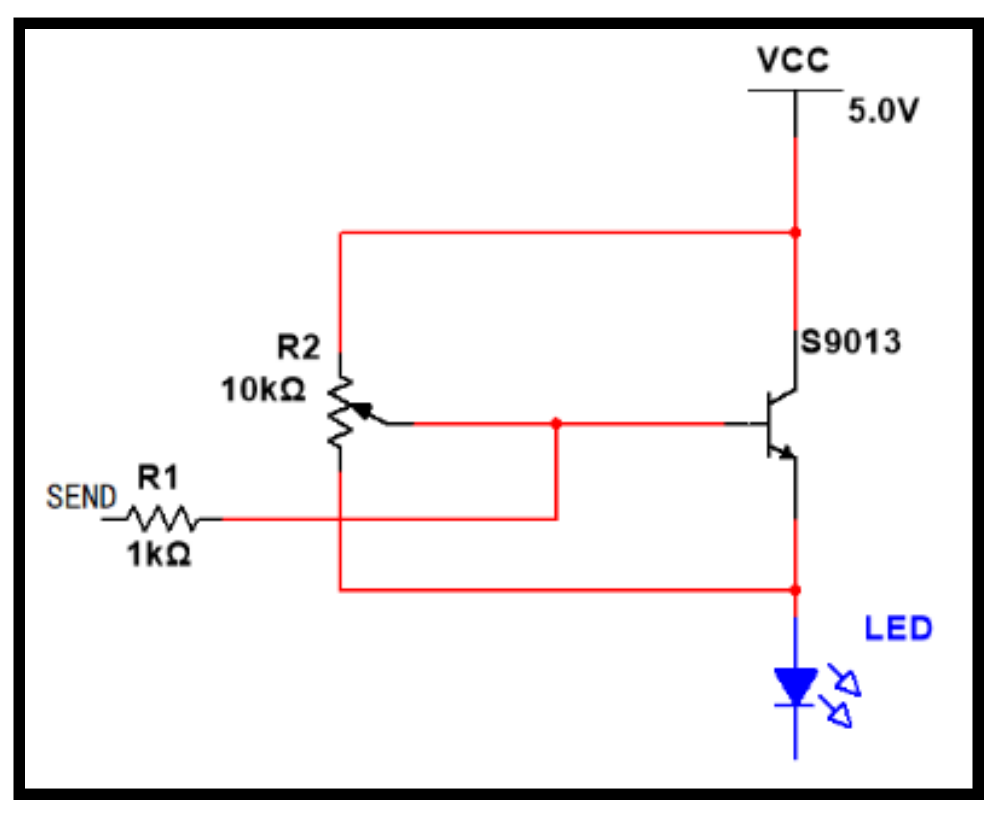
4.1. Design of the Transmitter
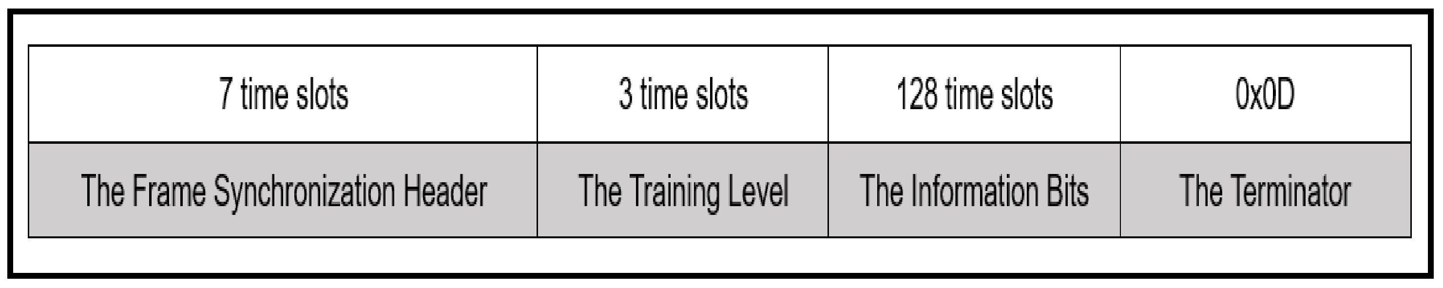
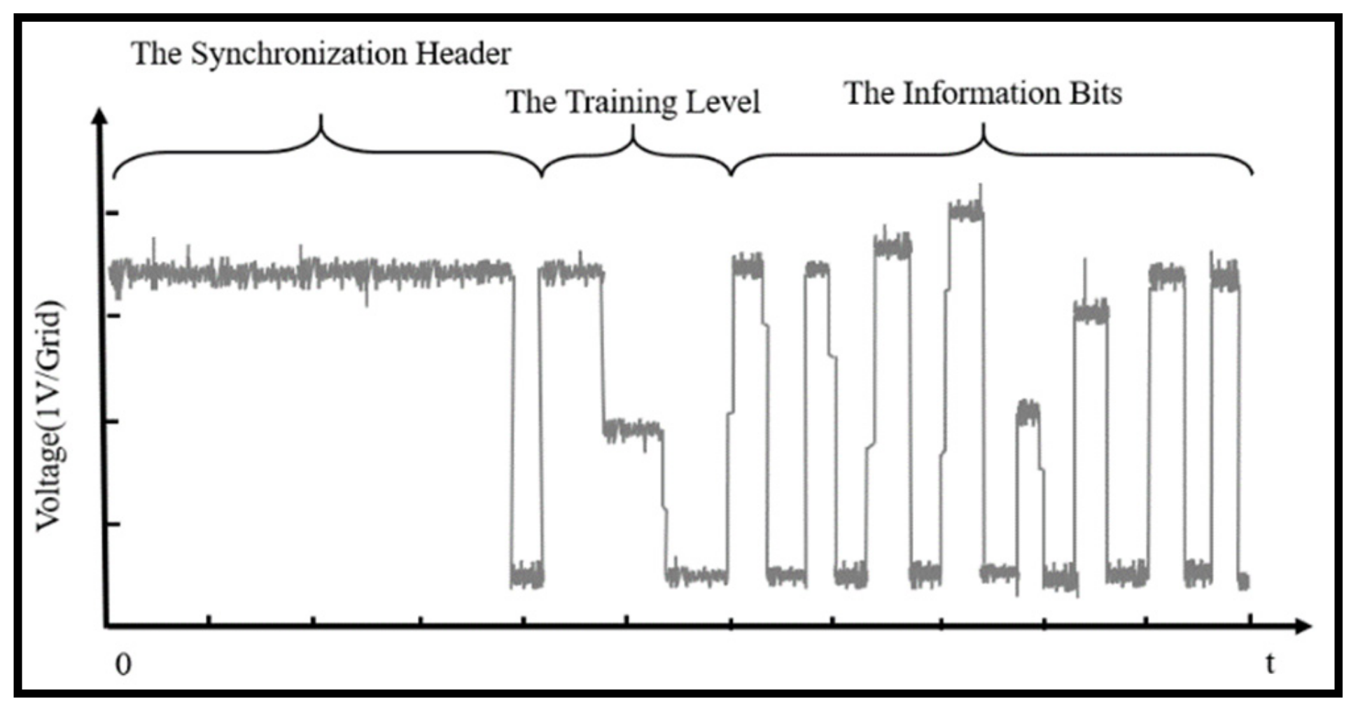
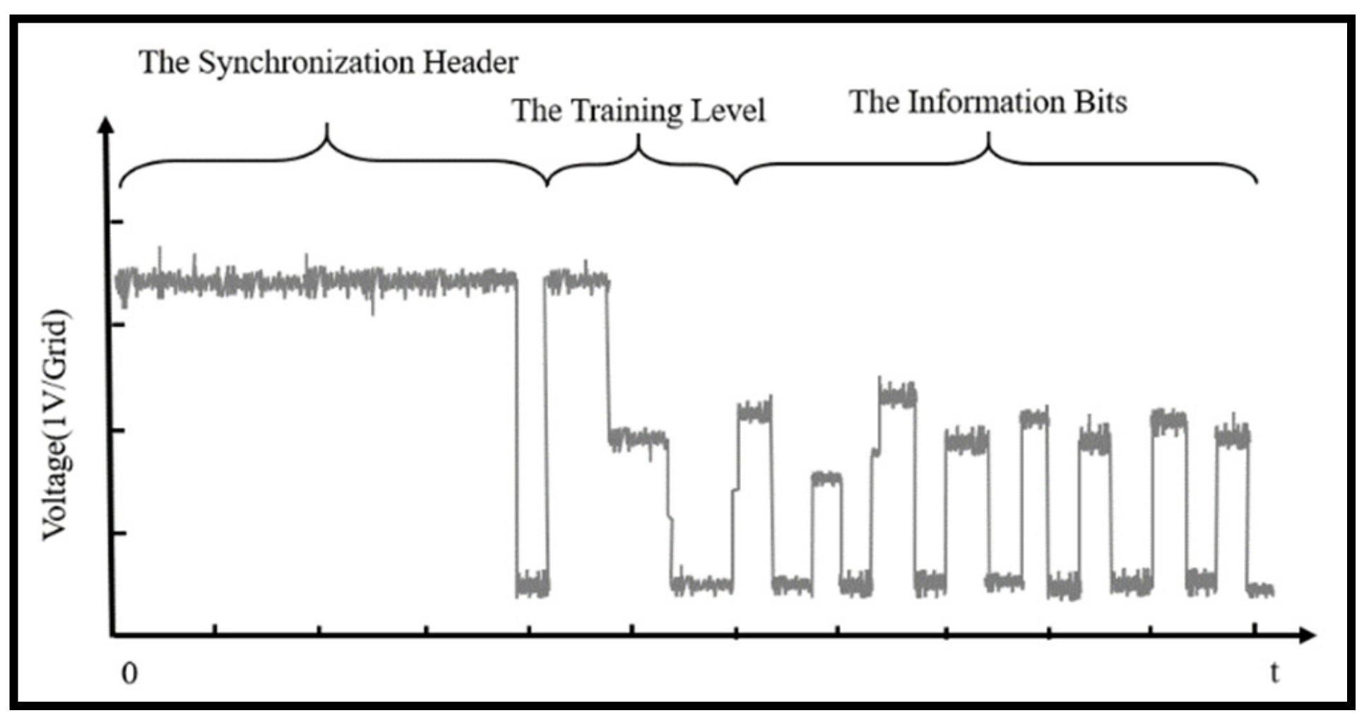
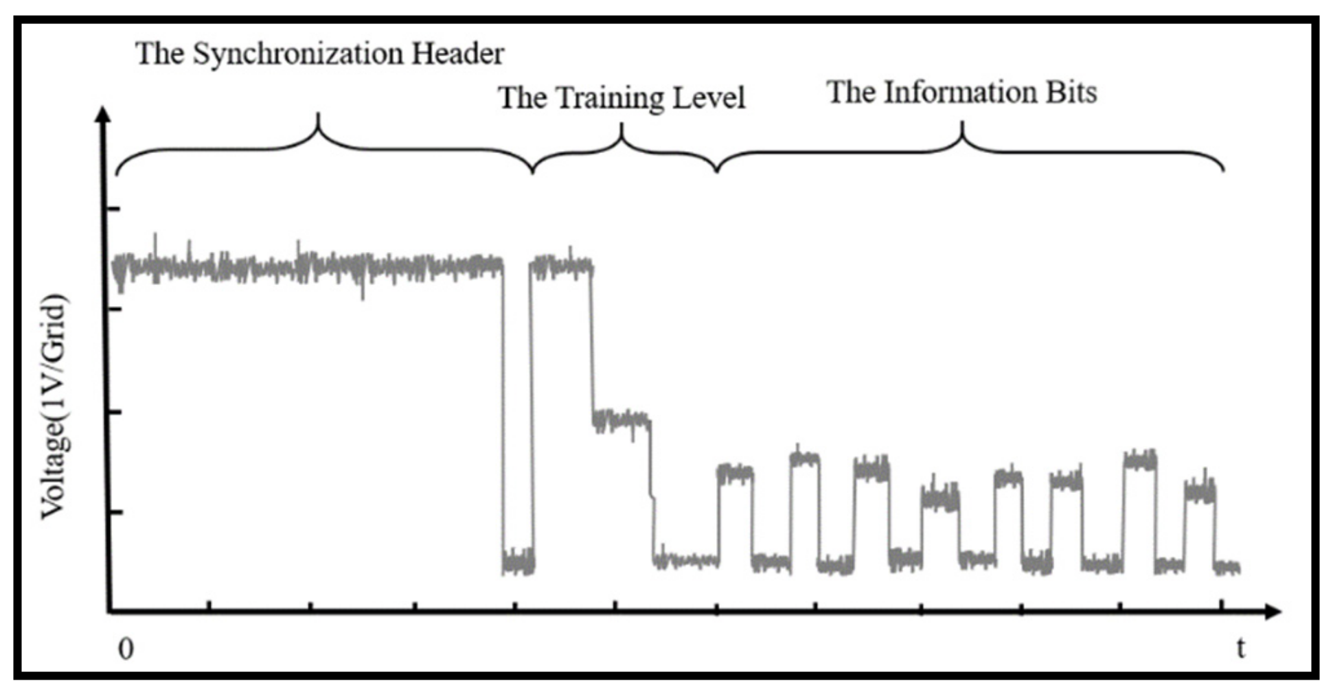
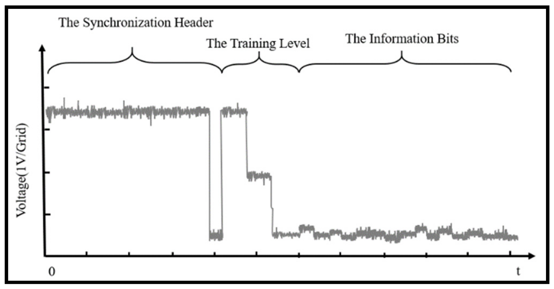
The main modules of the transmitter circuit are the GSM-MPAPM modulator, the power amplifier, the LED driver, and the array of LED wicks. All of the modules work normally under the control of the C8051F330 microcomputer, which was designed by Silicon Labs. Although it is an 8-bit microcomputer, the C8051F330 has a high-speed core of CIP-51, which is fully compatible with the 8051. This microcomputer was our first choice for communication design.
The input data processed by the transmitter are firstly generated by the Tera_Term, which is usually used to produce serial data in a communication system. Secondly, the serial data is separated into two data stream groups, namely, the LED combinations and the information bits. The bits are processed according to mapping tables. This procedure is performed while using the GSM-MPAPM modulator, of which the C8051F330 plays a key role.
A power amplifier is set as the primary amplification before the driver circuit to improve the drive capability of the transmitter to the wicks since the power of the white LED wicks used in the system is 2 W. The corresponding circuit is shown in Figure 5. In the power amplifier, the LM386 is chosen as an amplifier due to its low power consumption and weak harmonic distortion. By adding an external capacitor between pin 1 and pin 8, the voltage gain can be adjusted to any value up to 200. The power consumption of the LM386 at a static state is only 24 mW at the supply voltage of 5 V.
The triode S9013 is employed to form a common-shot amplification and drive circuit in the single LED driver circuit, which is shown as Figure 6. The output signals from the power amplifier are inputted into the circuit through the SEND pin. When there is high input, the S9013 is turned on and the corresponding LED is activated to light up. When there is low input, there is no current flowing through the S9013 and the LED is off.
The receiver circuit mainly consists of three parts, i.e., the photodetector, the amplifier, and the GSM-MPAPM demodulator. Figure 7 shows that the resistance value of the photodiode LED1 decreases if it detects optical signals, which thereby forces the positive input voltage of the dual voltage comparator LM393 to decrease; the inverted input voltage is determined by the variable resistance R 2 . Therefore, when the photosensitive detector detects obvious optical signals, the voltage of the positive input is less than that of the inverted input, the output of LM393 is low, and LED2 is on. If the photosensitive detector does not detect obvious optical signals, then the voltage of pin 3 is more than that of pin 2, the output is high, and LED2 is off. The sensitivity of the whole photodetector system can be changed by adjusting the value of   R 2 , according to indoor light interference.
The amplitude of the photodetector’s output signals cannot be satisfied with the demodulation threshold; therefore, the signals must be amplified. In Figure 8, The high frequency triode 2SC1815 is introduced to form a secondary amplifier circuit, which is not only cost-effective, but it also obtains better gain than the operational amplifier.

4.2. Frame Format

Figure 9 shows the frame format of the information bits, which consists of four parts: The synchronization header of the frame, the training level, the information bits, and the terminator. The synchronization header of the frame uses a high level of six time slots and a low level of one time slot. To eliminate the effects of ambient light, the training levels are added before the information bits. Finally, the signal 0 × 0D is used to represent the end of a frame.
The character sent by the serial debugging assistant at the transmitter is displayed in an ASCII format. The eight information bits are conveyed with (16,1,2)GSM-MPAPM. Figure 10 shows the processes for generating and receiving information bits at the transmitter and receiver.

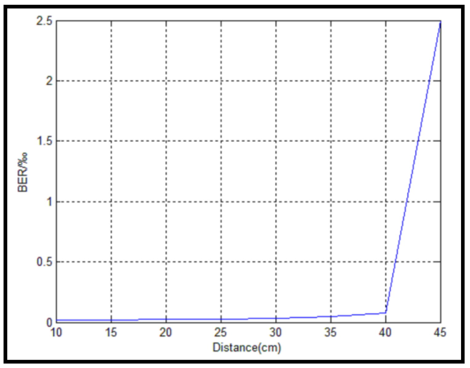
5. Results and Analysis

Measurements were made in a laboratory that was 4 m long, 3 m wide, and 4 m high, in the presence of other light sources in an indoor environment. It was supposed that the light emitting from the LEDs was on line of sight. At the transmitter, there were five LEDs, each with 2 W of power. The maximum output current of the pins on the C8051f330 was 25   mA , and the drive capability of the designed LED drive circuit was limited; the luminous power in the measurement was only 1.5 W. Furthermore, the C8051f330 clock influenced signal generation at the transmitter. Thus, 25 kb/s was chosen as the transmission rate of the information bits in the experiment.
This experiment firstly analyzed two activated LEDs which transmitted eight information bits at a time in the system. The different peak values of the voltage were obtained by changing the distance between the photodetector and the LEDs. The photodetector faced LED1, but all LEDs were at the same level and each was a different distance from the photodetector. Therefore, the different values were obtained according to LED combinations. In Figure 11, Figure 12, Figure 13 and Figure 14 seven high-level synchronization headers were followed by three training levels. The measured peak value of the voltage decreased from 4.15 V, 2.30 V, 1.40 V, to 0.8 V when the distance between the photodetector and the LEDs increased from 10 cm, 20 cm, 30 cm, to 40 cm. It could be seen clearly that in Figure 14, when the distance between the photodetector and the LEDs was 40 cm, the measured peak value of the voltage was almost close to that of the noise. The received signals were drowned in the noise at this moment. The BER performance was also analyzed in this experiment. Figure 15 shows that the BER remained below the value of 1.5   ×   10−4 when the distance was within 40 cm. However, when the distance exceeded 40 cm, the value rapidly increased. The results of the peak value of the voltage and the BER performance of the received signals both demonstrated that the distance between the photodetector and the LEDs was a very crucial parameter for the proposed scheme in the indoor short-distance VLC. This was mainly due to the use of a single photodetector for the intensity modulation/direct detection demodulation at the receiver. The illumination intensity decreased as the distance increased. Once the distance exceeded a threshold that guaranteed normal communication, multiple levels of interference appeared in the received signals. From the five figures above, it was drawn that the threshold of the distance was 40 cm. Ultimately, the aliasing signals prevented the original signals from being modulated. Furthermore, the luminous power of 1.5 W in this experiment might have been a factor that influenced the BER performance.
When the string of the information bits with the value of 10100101110000110011110011100110 was transmitted by Tera_Term at the transmitter, the receiver correctly received the string. In this test, the BER performances of GSM-MPAPM, V-MPAPM, MPAPM, and ACO-OFDM were compared. Among them, the latter three were mentioned in [5,9,11], respectively. Figure 16 shows that, within the range of the observation distance that was set between 15 cm and 23 cm, as the distance increased, the proposed (16,1,2)GSM-MPAPM, V-MPAPM, and MPAPM all had a stable performance in the BER, while the BER of ACO-OFDM gradually raised. This was because when the OFDM was applied to the VLC, due to the nonlinear response of the LED, it caused a higher BER than the single carrier modulation, such as GSM-MPAPM, V-MPAPM, and MPAPM, which were compared in Figure 16. At the same time, the (16,1,2)GSM-MPAPM had a better BER performance as compared to V-MPAPM and MPAPM obviously. That is because, as the distance increased, the channel fading was getting more and more serious, the (16,1,2)MPAPM provided an increase in spatial diversity via the two activated LEDs, which causes an improvement in the BER.
Three dimming coefficients were chosen and an illuminance curve was drawn through measurements in Figure 17 to verify the relationship between the illuminance and the distance of the (16,1,2)MPAPM. It can be seen from the curve that the illuminance decreased as the distance increased over the three different dimming coefficients. This caused a decrease in the peak value of the voltage and an increase in the BER. For p1, the system had a stable dimming effect when it was kept within the measurement distance, but the illuminances of all of the distances were slightly lower than the other two values. For p2 and p3, there were sudden changes at some values, i.e., 14 cm, 20 cm. Therefore, p1 was the best choice when a stable dimming was considered.

6. Conclusions

In this paper, an efficient data transmission scheme was successfully implemented in a designed indoor VLC system. The experiments demonstrated that the proposed GSM-MPAPM modulation worked normally so long as the distance between a transmitter and a receiver was within 40 cm, and the BER performance was inversely proportional to the distance. Furthermore, GSM-MPAPM had a better BER performance than VMPAPM, MPAPM, and ACO-OFDM when the same distance was used. This was because activated LEDs, of which there are usually multiple, provide an increase in spatial diversity to resist communication fading. Additionally, the differentiated dimming strategy caused a stable dimming effect on the variety of light in the environment.

Author Contributions

This research article contains three authors, including J.-J.B., who graduated from Communication and Information System, was responsible for conceiving and designing the modulation algorithm, designing the embedded hardware system together with C.-L.H., doing the experiments, and writing the paper and the replies. C.-L.H., was charged of analyzing the data and designing the embedded hardware system together with J.-J.B., J.-F.T., who was charged for proposing many helpful suggestions on the conception, format and writing of this paper. With the author’s help, this study can be completed as schedule.

Funding

This research was funded by [Social Science and Technology Development of Dongguan Science and Technology Bureau] grant number [2019507156746], [School-Enterprise Cooperation Horizontal Research of Dongguan Polytechnic] grant number [2018H64], [Technical R&D and service team of Dongguan Polytechnic] grant number [CXTD201802].

Conflicts of Interest

The authors declare no conflict of interest.

References

  1. Elgala, H.; Mesleh, R.; Haas, H. Indoor Optical Wireless Communication: Potential and State-of-Art. IEEE Commun. Mag. 2011, 49, 56–62. [Google Scholar] [CrossRef]
  2. Grubor, J.; Randel, S.; Langer, K.D. Broadband Information Broadcasting Using LED-Based Interior Lighting. J. Light. Technol. 2008, 26, 3883–3892. [Google Scholar] [CrossRef]
  3. Lou, S.; Gong, C.; Wu, N. Joint Dimming and Communication Design for Visible Light Communication. IEEE Commun. Lett. 2017, 21, 1043–1046. [Google Scholar] [CrossRef]
  4. Jie, L.; Maite, B. Adaptive M-PAM for Multiuser MISO Indoor VLC Systems. In Proceedings of the 2016 IEEE Global Communications Conference, Washington, DC, USA, 4–8 December 2016; pp. 1–6. [Google Scholar]
  5. Thai-Chien, B.; Mauro, B.; Suwit, K. Theoretical Analysis of Optical Spatial Multiple Pulse Position Modulation. In Proceedings of the 2018 Global Communications Conference, Abu Dhabi, UAE, 9–13 December 2018; pp. 112–120. [Google Scholar]
  6. Mostafa, H.; Martin, J.; Peter, J. Visible Light Communication based on Offset Pulse Position Modulation Using High Power. In Proceedings of the 32nd General Assembly and Scientific Symposium of the International Union of Radio Science, Montreal, QC, Canada, 19–26 August 2017; pp. 223–228. [Google Scholar]
  7. Zhang, D.-F.; Zhu, Y.-J.; Zhang, Y.-Y. Multi-LED Phase-Shifted OOK Modulation Based Visible Light Communication Systems. IEEE Photonics Technol. Lett. 2013, 25, 2251–2254. [Google Scholar] [CrossRef]
  8. Yamga, G.M.; Ndjionge, A.R.; Ouahada, K. Low Complexity Clipped Frequency Shift Keying for Visible Light Communications. In Proceedings of the IEEE 7th International Conference on Adaptive Science & Technology, Accra, Ghana, 22–24 August 2018; pp. 62–70. [Google Scholar]
  9. Chumchewkul, D. Performance Evaluation of VPPM Visible Light Communications based on Simulation with Experiment’s Parameters. In Proceedings of the 15th International Conference on Electrical Engineering, Electronics, Computer, Telecommunications and Information Technology, Chiang Rai, Thailand, 18–21 July 2018; pp. 26–35. [Google Scholar]
  10. Zhang, M.; Zhang, Z. An optimum DC-Biasing for DCO-OFDM system. IEEE Commun. Lett. 2014, 18, 1351–1354. [Google Scholar] [CrossRef]
  11. Armstrong, J.; Lowery, A.J. Power efficient optical OFDM. Electron. Lett. 2006, 42, 370–372. [Google Scholar] [CrossRef] [Green Version]
  12. Su, S.; Chung, W.; Wu, C. Exploiting Entire GSSK Antenna Combinations in MIMO Systems. IEEE Commun. Lett. 2015, 19, 719–722. [Google Scholar] [CrossRef]
  13. Olanrewaju, H.; Thompson, J.; Popoola, W. Generalized Spatial Pulse Position Modulation for Optical Wireless Communications. In Proceedings of the 2016 IEEE 84th Vehicular Technology Conference, Montreal, QC, Canada, 18–21 September 2016; pp. 245–249. [Google Scholar]
  14. Qin, Y.L. Performance Analysis of MPPM Based Wireless Optical Communication System. Master’s Thesis, Xidian University of Electronic Technology, Xi’an, China, 2018. [Google Scholar]
  15. Effros, M.; Goldsmith, A.; Liang, Y. Generalizing Capacity: New Definitions and Capacity Theorems for Composite Channels. IEEE Trans. Inf. Theory 2010, 56, 3069–3087. [Google Scholar] [CrossRef] [Green Version]
  16. Younis, A.; Serafimovski, N.; Mesleh, R. Generalised Spatial Modulation. In Proceedings of the 44th Asilomar Conference on Signals, Systems and Computers, Pacific Grove, CA, USA, 7–11 November 2010; pp. 1498–1502. [Google Scholar]
  17. Younis, A.; Basnayaka, D.A.; Hass, H. Performance Analysis for Generalised Spatial Modulation. Eur. Wirel. 2014, 45, 1–6. [Google Scholar]
Figure 1. The generalized spatial modulation (GSM) system model.
Symmetry 11 01232 g001
Figure 2. The indoor visible light communication (VLC) system model based on generalized spatial modulation with multi-pulse amplitude and position modulation (GSM-MPAPM).
Symmetry 11 01232 g002
Figure 3. The function of each bit in a time slot.
Symmetry 11 01232 g003
Figure 4. The overall VLC system architecture.
Symmetry 11 01232 g004
Figure 5. The power amplifier circuit.
Symmetry 11 01232 g005
Figure 6. The single LED driver circuit.4.2. Design of the Receiver.
Symmetry 11 01232 g006
Figure 7. The photodetector.
Symmetry 11 01232 g007
Figure 8. The signal amplifier.
Symmetry 11 01232 g008
Figure 9. The frame format of the information bits.
Symmetry 11 01232 g009
Figure 10. The process for the generation and reception of information bits (a) at the transmitter; and, (b) at the receiver.
Symmetry 11 01232 g010
Figure 11. The amplified waveform of the received signals (10 cm).
Symmetry 11 01232 g011
Figure 12. The amplified waveform of the received signals (20 cm).
Symmetry 11 01232 g012
Figure 13. The amplified waveform of the received signals (30 cm).
Symmetry 11 01232 g013
Figure 14. The amplified waveform of the received signals (40 cm).
Symmetry 11 01232 g014
Figure 15. The relationship between the BER (‰) and the distance.
Symmetry 11 01232 g015
Figure 16. Comparisons of the bit error ratios (BERs) of different modulations.
Symmetry 11 01232 g016
Figure 17. The relationship between the illuminance and the distance under three dimming coefficients.
Symmetry 11 01232 g017
Table 1. Light-emitting diode (LED) combinations.
Grouped BitsLED Combinations
000(1,2)
001(1,3)
010(1,4)
011(1,5)
100(2,3)
101(2,4)
110(2,5)
111(3,4)
Table 2. The MPAPM mapping rules.
Information BitsMapping RulesInformation BitsMapping Rules
Front_4bits0000Transmit in time slot 1Front_4bits1000Transmit in time slot 9
0001Transmit in time slot 21001Transmit in time slot 10
0010Transmit in time slot 31010Transmit in time slot 11
0011Transmit in time slot 41011Transmit in time slot 12
0100Transmit in time slot 51100Transmit in time slot 13
0101Transmit in time slot 61101Transmit in time slot 14
0110Transmit in time slot 71110Transmit in time slot 15
0111Transmit in time slot 81111Transmit in time slot 16
Middle_1bit0The amplitude is U 1
1The amplitude is U 2
Table 3. Comparison of information bits per symbol.
Modulation SchemesBits Transmitted per Symbol (bits)
MPAM l o g 2 M
MPPM l o g 2 C Q P
VPAPM l o g 2 Q × M
VMPAPM l o g 2 C Q P × M
GSM-MPAPM l o g 2 C Q P × M × C N t N s
Table 4. The dimming strategy.
The Dimming CoefficientsThe Principle of Dimming Control
p1 = 0.2 Symmetry 11 01232 i001
p2 = 0.4 Symmetry 11 01232 i002
p3 = 0.6 Symmetry 11 01232 i003
p4 = 0.8 Symmetry 11 01232 i004

