1. Introduction
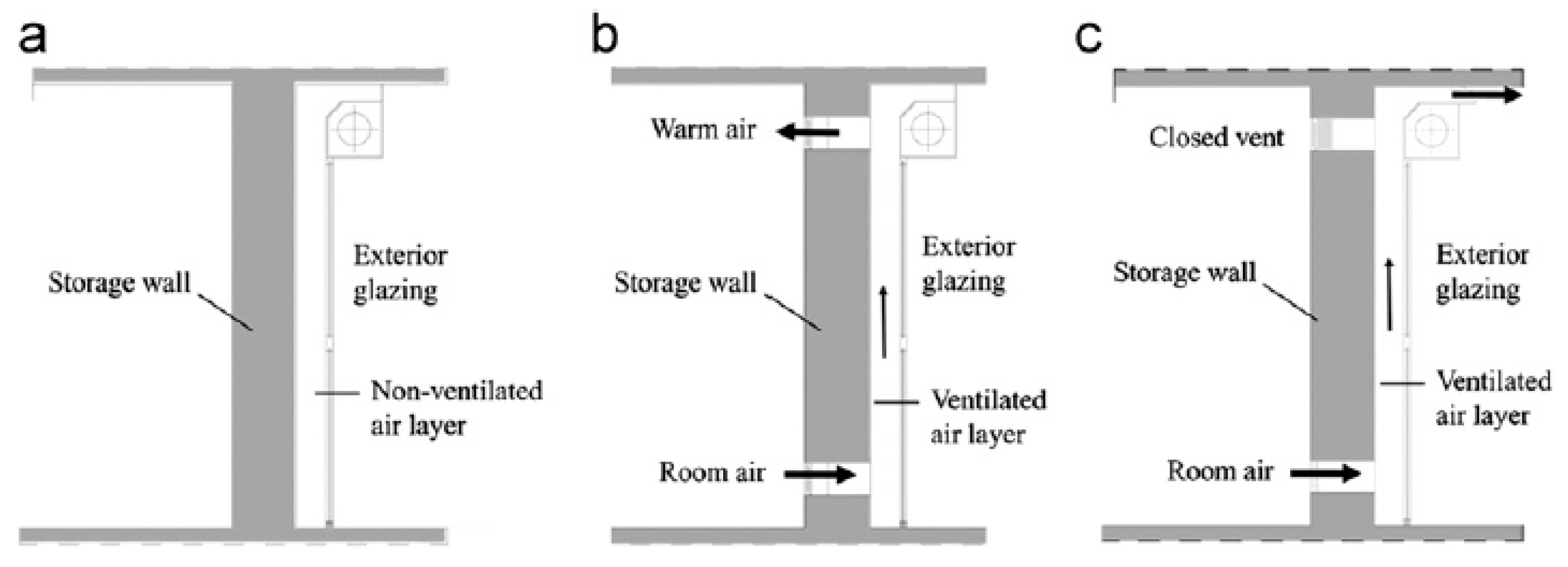
Progressive changes in the climate have forced scientists to take an interest in passive heating systems that will reduce the amount of pollutants released into the atmosphere by reducing heat demand. Particular attention should be paid to heating systems, which are currently the main source of toxic compounds in the atmosphere in Poland. The proposed Trombe wall system uses solar radiation energy by accumulating it in a material with a high heat capacity, such as concrete. It enables the heat to be slowly released into a room, both during the day and also at night. The mechanism of heat exchange, in this case, involves radiation and conduction. The ventilated version of this storage wall includes air circulation, with heat also being provided by convection. This solution includes air ducts in the upper and lower part of the wall. Cold high-density air flows from the room into the Trombe wall air gap through the lower vent, heats up as a result of solar radiation, reduces its density, and then rises up. The resulting density difference causes natural circulation in the system under the influence of buoyant forces. The operating principle is illustrated in
Figure 1.
The Trombe wall in its classic solution is already a well-known technology in countries with high solar gains during the day and low temperatures at night, and therefore especially in dry and hot climates. This is due to the fact that this element can function in heating and cooling modes.
Table 1 contains a summary of the results of research conducted by scientists on real objects, and also numerical simulations that were carried out to optimize the given solution.
The classic Trombe wall solution is still being modified and developed in order to increase its efficiency in the heating and cooling operation mode. This is conducted by the addition and modification of structural elements. A list of solutions on which research works are conducted is presented in
Table 2.
2. Materials and Methods
In the conducted simulations, a ventilated Trombe wall, constituting the southern facade of a room measuring 5.2 m × 4.2 m× 2.6 m, was considered. The simplest and cheapest construction solutions were chosen; the 348 mm thick storage wall made of concrete, covered with a 2 mm thick black paint as an absorber. An air gap of 150 mm separates the absorber from the 4 mm thick glazing. The wall has three upper and three lower ventilation ducts with dimensions of 300 mm × 200 mm. The properties of the used materials are summarized in
Table 3, which include:
—thickness,
—density,
—specific heat,
—heat transfer coefficient,
—solar absorption coefficient, and
—refractive index of a material.
The external walls of the room with a thickness of 0.442 mm were modeled by designating the appropriate simulation conditions. In order to consider their insulation from the environment, the weighted average densities, specific heat, and heat transfer coefficient of the individual layers were determined. The properties of the individual layers are summarized in
Table 4. The selection of insulation was conditioned by obtaining a heat transfer coefficient lower than 0.14 W/m K, which corresponds to that of energy-saving buildings. The calculations took into account the heat transfer resistance on both the inside and outside.
2.1. Numeric Mesh of the Room
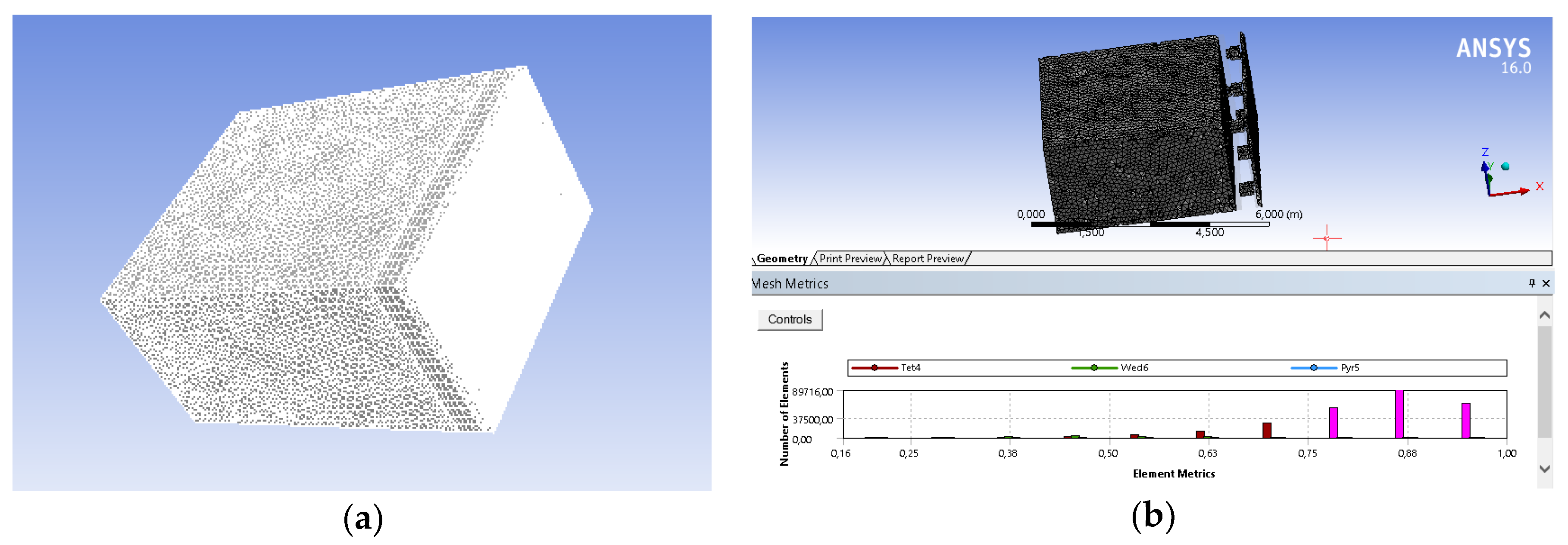
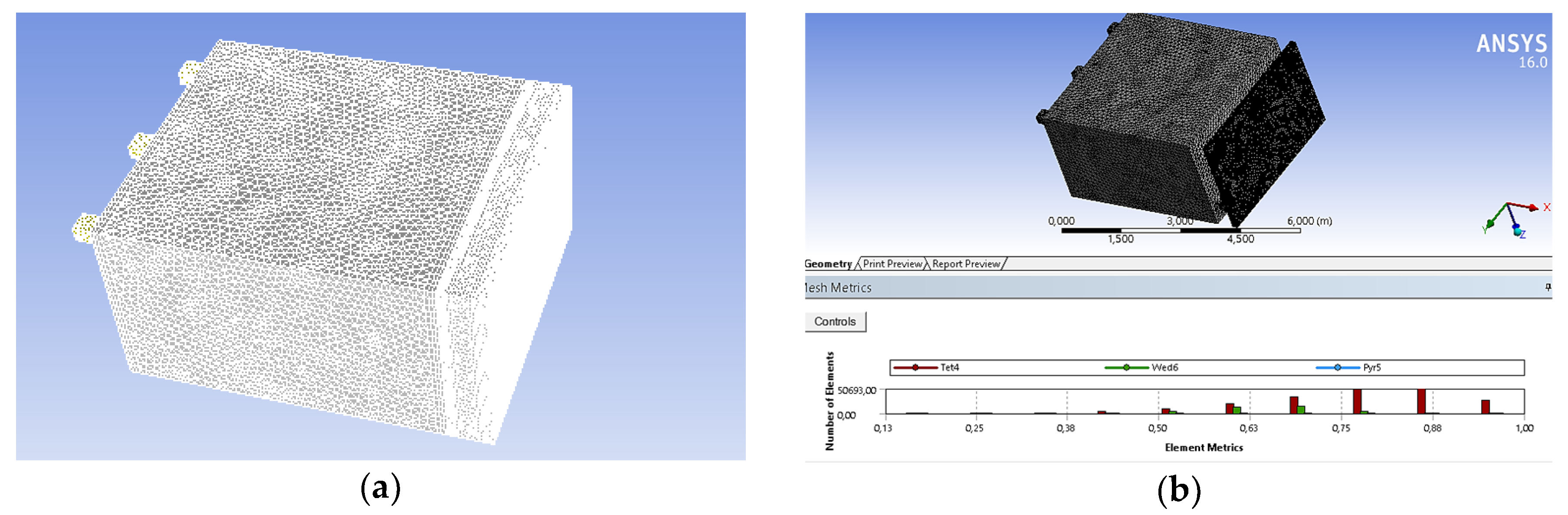
In order to build a numerical mesh of the room, a 3D model of the considered geometry was made using CATIA software. This model should be divided into three elements: air, which is the medium in question, the storage wall, and the absorber. Glazing was simulated by appropriate settings of the boundary conditions in order to minimize the number of mesh elements. The obtained geometries were implemented in the Ansys Fluent 16.0 environment. Afterwards, a mesh was created (
Figure 2a) with a bigger number of elements within the connections of the individual geometry elements, in particular at the contact point of the storage wall and the air in the room, where the largest changes in temperature distribution can be observed as a result of heat dissipation from the storage wall to the room. Individual meshes were checked with regards to their quality, obtaining in most elements an index value within the range of 0.7–1.0 (
Figure 2b). The absorber, due to its small thickness, was the biggest challenge when creating the mesh. A high mesh quality could only be obtained by increasing the number of mesh elements, which in turn resulted in a significant increase in the calculation time. However, since the essential element of the experiment is the medium, the quality of the absorber mesh introduces an acceptable range of errors.
2.2. Boundary Conditions
The boundary conditions for the implementation of the simulation for the heating period were determined on the outer walls of the room. For the ceiling and the north, east, and west walls, the determined value of the outside air temperature and the heat transfer coefficient were estimated and increased in order to also consider windy weather conditions. The temperature was adopted for a certain hour in accordance with meteorological data for Wroclaw. The same conditions were used for the floor, but the temperature corresponds to the ground temperature and the heat transfer coefficient changes. All the walls do not participate in solar radiation tracking, and calculations for heat transfer by radiation are also not conducted. For the southern wall, a condition was established on the external glass covering, and it includes air temperature and the heat transfer coefficient, and for the radiation calculations, it includes tracking of solar radiation with the semi-permeability condition. On the connections of the glass with the air gap, the gap with the absorber, the absorber with the storage wall, and also the walls with the air in the room, the condition of connecting the walls (interface, coupled wall) was determined. The replacement material and wall thickness were also specified in order to avoid the creation of additional meshes and connections between the walls. A list of conditions is given in
Table 5. The heat transfer coefficient from the outside air to the wall was estimated by assuming the temperature of the layer adjacent to the wall and was then increased to take into account windier days.
The air temperature
is the temperature for a given hour during the selected representative day on which the simulation is carried out. The lowest average temperature, according to meteorological data, was determined for the month of January with a value of −0.7 °C. Due to the fact that the proposed passive system is only intended to support the heating system, the selected day has daytime temperatures close to the average value. Choosing extremely low temperatures would not reflect the work of the system on most days when its role would be greater (heat losses to the environment increase at very low outside temperatures, and therefore, operation of the support system is necessary). Thus, 16 January (data for TMY [
33]) was chosen as the representative day, for which the temperatures are summarized in
Table 6.
The ground temperature was assumed as a constant value for a given month at a depth of about 1 m [
34]. For January, it is equal to around 1 °C.
2.3. Settings of the Module That Are Responsible for the Calculations
Carrying out the simulation requires taking into account relevant equations, which the program solves with a given number of iterations. The governing equations of Navier Stokes were linked to the RANS turbulence model. The used realizable two-equation turbulence model
is necessary due to the air circulation between the room and the air gap, which is caused by the resulting density difference. This condition also requires consideration of the effect of gravity by determining the Boussinesq model. Another equation included in the calculations, in order to observe the heat exchange between the external environment and the air inside the room, is the energy equation. This allows appropriate boundary conditions to be set that reflect the conducted simulation. The inclusion of radiation greatly complicates the calculations, often causes errors, and also significantly extends the calculations. Therefore, this model was simplified by excluding the consideration of radiation for individual elements, and only solar radiation tracking [
35] was determined for the southern wall. This option requires entering the latitude and longitude of Wrocław and then orienting the solid in accordance with the selected directions. This model allows a specific day of the year and the hour with accuracy to the nearest minute to be set for the conducted simulation. A coupled calculation system based on pressure and speed was used. The simulations were made based on the research carried out in [
36]. The mathematical notation [
36] should take into account the mass and moment equation for three-dimensional turbulent flow.
3. Results for the Passive Heating System
The simulations were carried out for the classic Trombe ventilated wall solution operating in the heating mode. Afterward, the effect of exchanging the storage material from concrete to brick, and also exchanging the single glazing to triple glazing filled with argon were examined. The simulation results focus on the temperature distribution throughout the entire section of the room, and also air circulation, which are crucial for achieving thermal comfort. The results obtained for individual hours are summarized in tabular and graphic form.
3.1. The Basic Solution
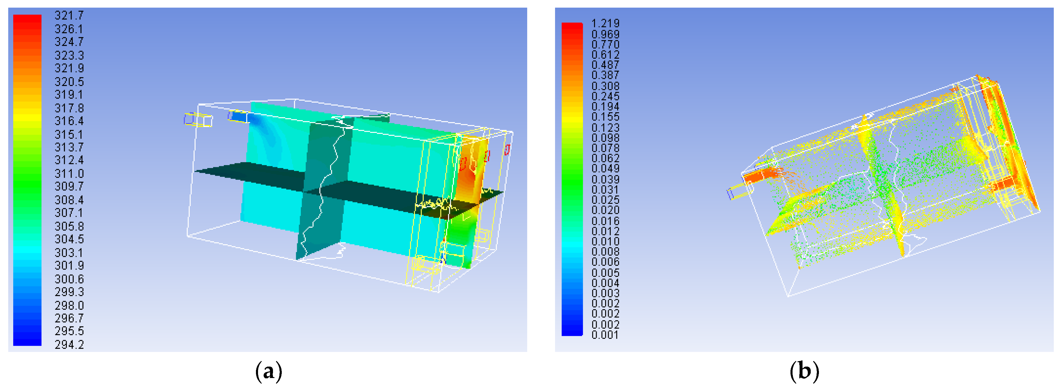
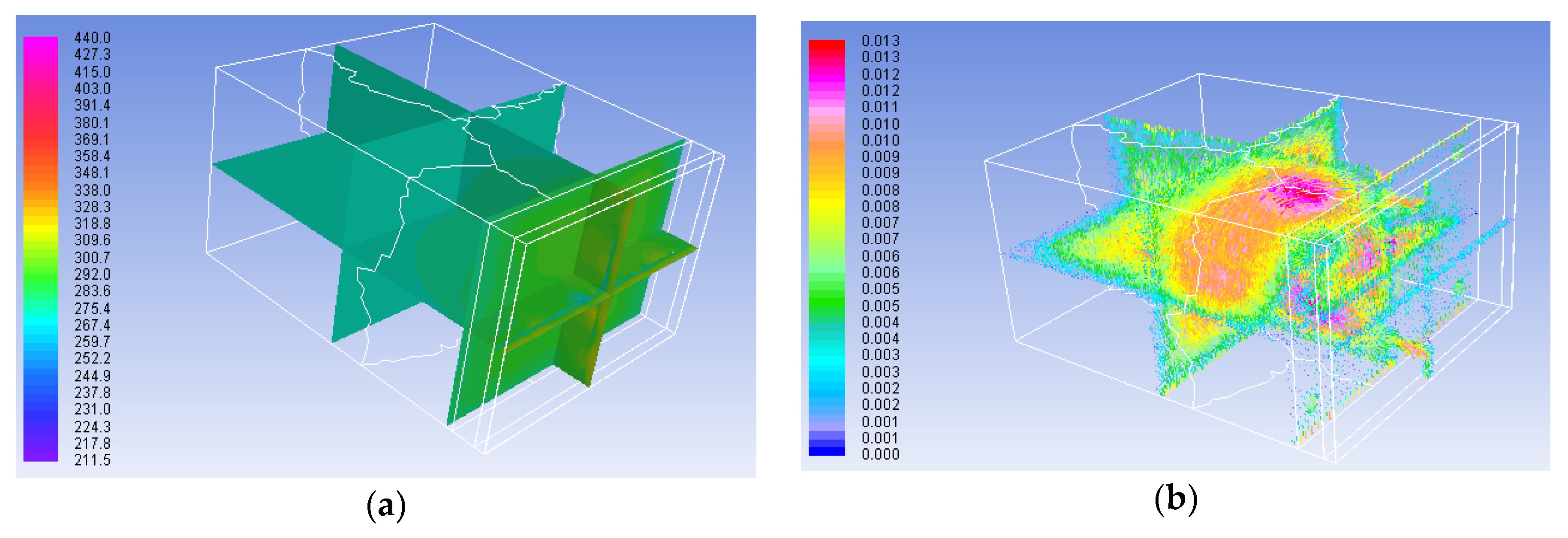
Simulations were carried out for the heating period, and temperature values were read from 10:00 to 14:00. Between 7:00 and 10:00, solar radiation is not intense enough to achieve a heating effect, and after 14:00, the radiation is no longer recorded by the meteorological station. Due to the calculations in the set state, it is not possible to test the heat release to the room at later hours. The temperature distribution in the room was presented on several main planes that are shown in
Figure 3a. In turn, the distribution of speed vectors is presented in
Figure 3b.
The result of each simulation consisted of a reading of the average temperature from the given plane. A summary of these values is given in
Table 7, and it includes ambient temperature
, the temperature in the middle of the room
the temperature of air by the storage wall
, the temperature on the connection between the absorber, and the wall
, the temperature of the storage wall from the room side
and the temperature of air in the gap
.
3.2. The Brick Storage Wall
An important element of the Trombe wall is the storage wall and its properties, which depend primarily on the used material. Other simulations were carried out for concrete, which is the most frequently chosen material in such constructions. An alternative suggestion may be the use of brick, which has a lower specific heat
, lower density
and a thermal conductivity coefficient with the value of
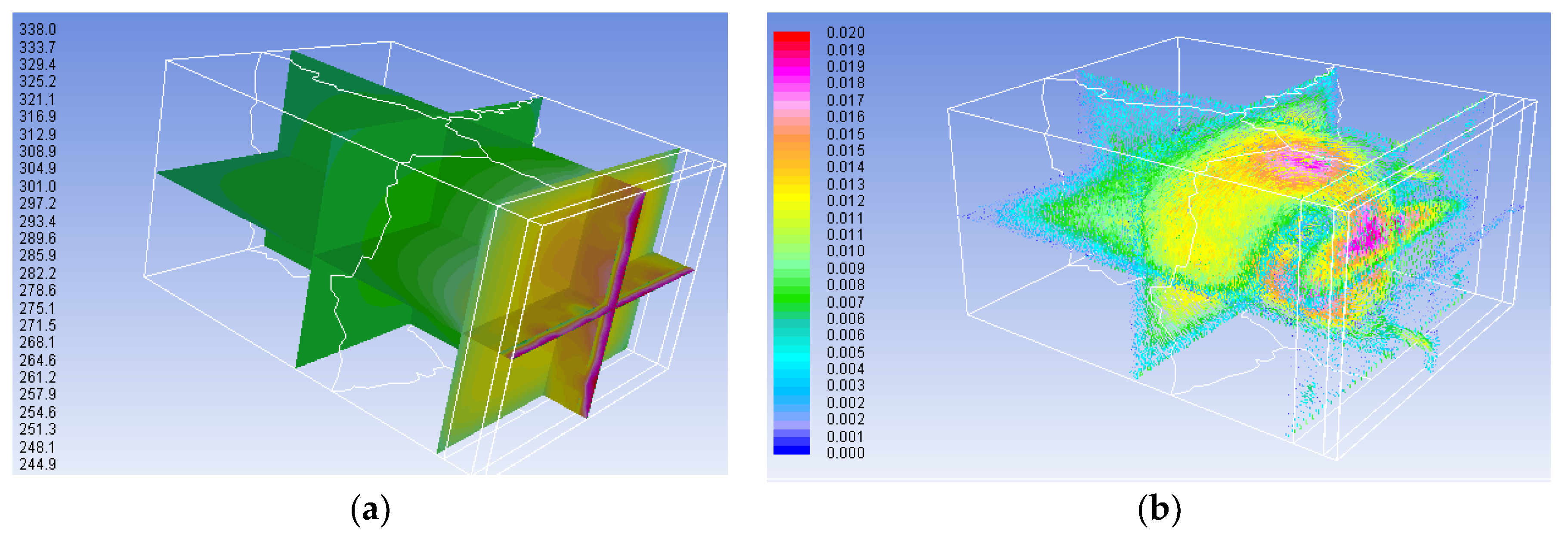
. This material is able to accumulate less heat, but at the same time, it delays heat transfer to the room. The resulting temperature distribution for 12:00 is shown in
Figure 4a, while the distribution of speed vectors is presented in
Figure 4b.
The average temperature values in the individual planes are summarized in
Table 8. Small differences of these results can be observed when compared to the simulation with the wall made of concrete.
3.3. Argon Filled Glazing
The basic solution of the Trombe wall is characterized by heat losses to the environment at the border of the glazing and the environment. This is associated with a large temperature difference between the heated air in the gap and the ambient temperature. The reduction of these losses, without significantly affecting the glass transmission, can be achieved by using glazing filled with a noble gas such as argon. Such a gas is characterized by a low thermal conductivity coefficient. Triple glazing with 4 mm thick glass and 14 mm thick argon filled spaces was considered in the simulation.
Table 9 summarizes the values of the parameters of this glazing, which were calculated as a weighted average based on the thickness of the layer.
The temperature distribution for 12:00 in the individual planes is shown in
Figure 5a, while the distribution of speed vectors is presented in
Figure 5b.
Analysis of the results contained in
Table 10 confirms the achievement of a higher temperature level on each surface. An increase in temperature within the storage wall and the absorber is especially noticeable, which confirms the fact that there are fewer heat losses to the environment.
3.4. Discussion of Results
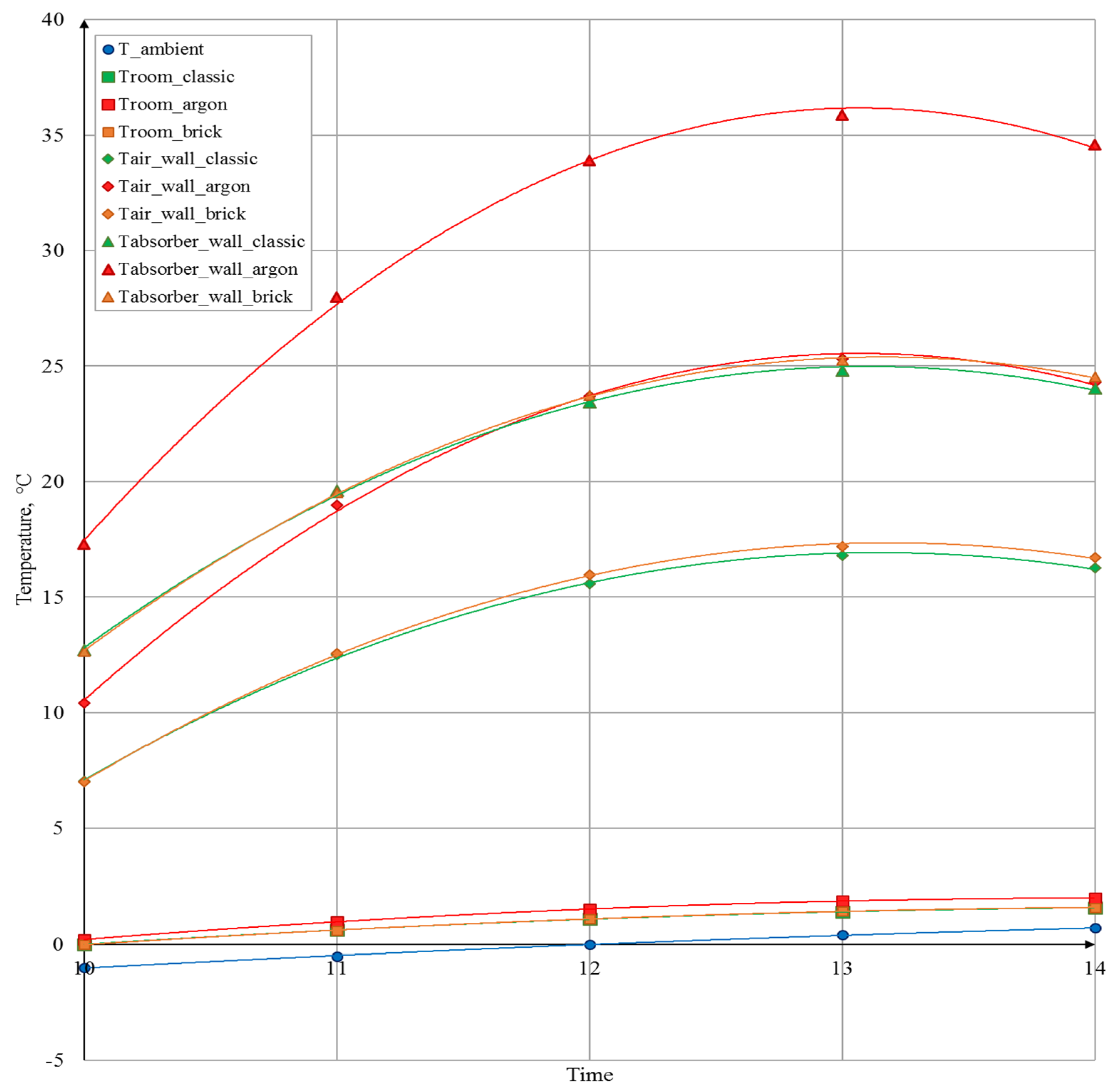
The heating level for the use of the selected technology is best reflected by the average temperature inside the room and the air temperature by the storage wall. The results for these quantities for the individual solutions are compiled on a common graph and shown in
Figure 6. This figure also contains the temperature at the connection of the absorber and the storage wall and the ambient temperature in order to show the appropriate reference point. A slight increase of the values can be observed for the storage wall made of brick, for which the temperature distribution in the room almost coincides with the trend line for the wall made of concrete. A significant increase in the values is noticeable when using glazing filled with argon.
When analyzing the obtained temperature distribution for the heating mode, an increase in the temperature in the middle of the room ranging from can be observed. Taking into account the large dimensions of the room and the fact that the analysis was conducted under steady-state conditions, this result is considered as rational. The air zone just next to the storage wall is characterized by temperatures within the range of , while the highest temperatures are achieved by the air in the gap, which receives heat by convection from the absorber. Higher values of temperature ranges were observed for the simulations with additional glazing, due to which heat losses to the environment are reduced. The impact of the change in the storage material is small, and the obtained results are only slightly higher than for the wall made of concrete.
The distribution of air speed vectors in the room when considering the heating mode enables a visible area of air circulation, caused by the difference in the density of cool and warm air, to be noticed. The maximum speed values are in the range of 0.013–0.020 m/s, which allows heat comfort to be maintained in the room. Higher velocity values were registered for the solution with argon filled glazing, which is associated with a greater temperature difference, and thus a greater difference in air density, which in turn is the driving force of the proposed solution.
4. The Trombe Wall Operating as a Cooling System
The operation of the Trombe wall in the cooling system, which has potential in the Polish climate, was also examined. For this purpose, the room geometry and simulation conditions were changed.
4.1. Changes in Geometry
New geometry and mesh elements were created for the cooling system (
Figure 7a). Ducts, which are the inlets of cooler air, were added to the top of the north wall. A 10 cm thick insulation was placed on the inner side of the storage wall, the properties of which are listed in
Table 11. The air was simulated according to the Boussinesq model, with the compressibility factor
equal to 0.003 (
Table 11).
The top ducts located in the upper part of the storage wall were closed, and warm air outlets located in the glazing were added. The air domain mesh with the quality scale of the elements is shown in
Figure 7b. In order to simplify the simulation conditions, the glazing and the north wall were implemented by setting appropriate boundary conditions. Due to the greater complexity of the geometry, the authors resigned from the absorber, which was characterized by weaker elements of its mesh. Instead, the solar radiation absorption coefficient for the storage wall was determined with a value that corresponds to the absorber, i.e.,
.
4.2. Boundary Conditions
The boundary conditions for the walls of the room when considering the cooling mode of operation were adopted in the same way as for the heating system. However, the glazing conditions were changed, which was included in the geometry. The heat transfer coefficient
was reduced to
in order to obtain atmospheric conditions that hinder the system’s operation and cause higher heating of the storage wall. The value of
, which was confirmed by the calculations, was left for the remaining walls. These conditions are summarized in
Table 12.
The outside air temperature divided into hours was adopted in accordance with TMY [
33]. The highest average temperature, equal to 17.8 °C, was recorded for August. Due to the fact that in the summer the cooling system is necessary at an outside temperature higher than the comfort temperature, and that there is also a risk of overheating the room during this period, the day with the highest outside temperatures was chosen, i.e., 15 August. The temperatures in the hours for which the simulations were performed are listed in
Table 13.
The ground temperature was assumed as a constant value for a given month at a depth of about 1 m [
34], and for August, it is around
. Due to the changed geometry of the room, two conditions regarding the air flow in the room were also added, which are presented in
Table 14.
On the ducts located on the north facade of the building, the air inlet condition was established with an inlet speed of 0.5 m/s, while on the ducts located in the glazing, the condition of the air outlet to the atmosphere was set at a relative pressure of 0 Pa. These conditions are shown in
Table 13.
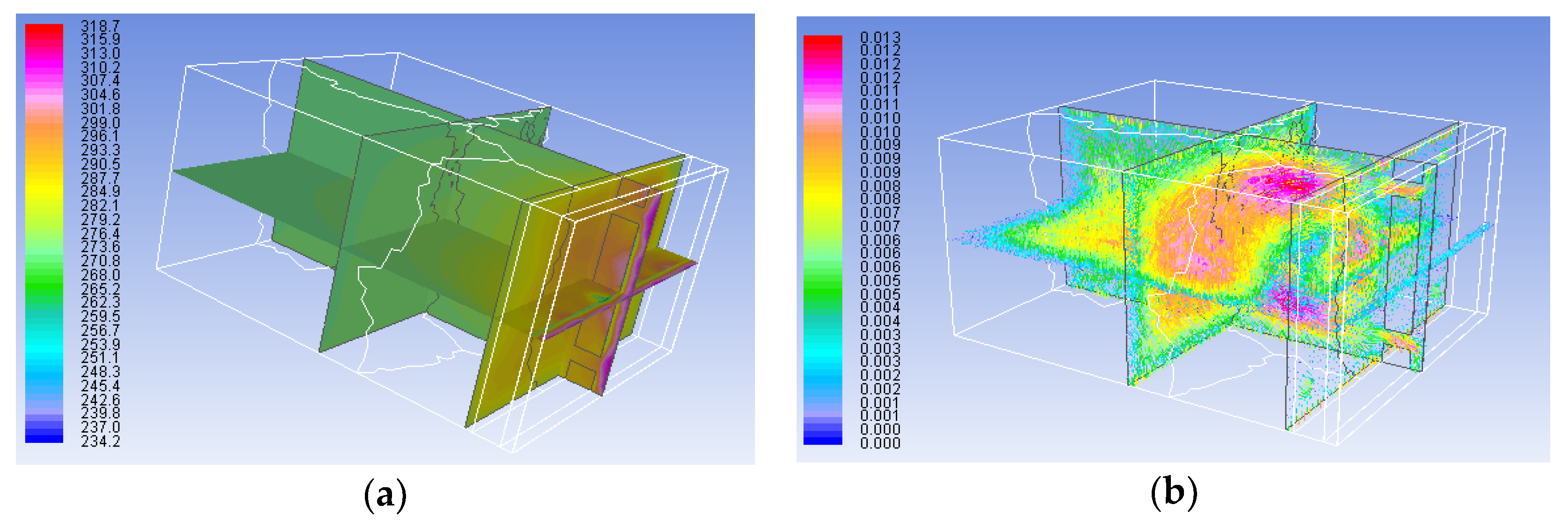
4.3. Simulation Results
The operation of this solution is based on the introduction of cooler air into the room from the north side. For the purpose of this simulation, a temperature of
lower than the ambient temperature, as well as the obtaining of air flow between the north and south side due to the difference in temperature, were assumed. The temperature distribution on the individual planes of the room (
Figure 8a), read at 12:00, clearly shows the inflow of cooler air, which, due to its higher density, falls to the bottom of the room. A warmer air zone is visible in the upper part of the room.
A flow of air into the room is visible, the stream of which is dispersed in the volume of air in the room, reaching higher velocity values at the edges of the geometry. The stream accelerates again in the ducts that connect the room to the gap and also in the air outlets to the environment.
The average temperature values were read for the individual planes located in the middle of the room
, at the connection of the storage wall and the absorber
, and in the air gap
. The maximum average room temperature decrease of
can be seen, while between 12:00 and 14:00, temperature equalization and a slight increase in room temperature can be noticed. This is due to the increase in the temperature of the absorber and the air in the gap as a result of higher intensity radiation at that time. The results are summarized in
Table 15.
5. Conclusions
The carried out simulations indicate the potential of the Trombe wall as a passive heating and cooling system for the climate of Wrocław. The maximum increase in the average air temperature in the analyzed room of was observed for the solution with argon filled glazing. The air temperature at the storage wall increases in relation to the ambient temperature within the range from for the classic solution, from for the solution with argon filled glazing, and from for the solution with the brick storage wall. The maximum temperature values are reached at the highest solar radiation, which occurs at 13:00.
Air circulation between the room and the air gap was observed, which confirms the heat transfer by convection, and thus proves the correctness of the simulation. The maximum air speed in the room reaches 0.013 m/s for the classic solution and for the solution with an exchanged storage material, while for the version with argon filled glazing, it is equal to 0.020 m/s. These values ensure comfort for residents.
When considering the cooling system, a maximum temperature drop of was achieved. In contrast, during the hours with the most sunshine, i.e., between 12:00 and 14:00, the highest temperatures of the absorber and the air in the gap are observed, which causes equalization and a slight increase in the average room temperature. This problem can be solved by improving the insulation of the wall or by increasing the air draft by using a solar chimney. The maximum recorded air speed in the gap was equal to 1.219 m/s, while the air speed in the room remained within the range of 0.020–0.245 m/s with an increase to 0.5 m/s around the ducts, which is determined by the inlet speed. These values enable the heat comfort of residents to be achieved.
Based on previous research, it can be concluded that in Polish climatic conditions, it is economically justified to use the simplest design solutions, for which the results of achieved room temperatures are comparable with more expensive technologies.
In further studies, it will be necessary to conduct analyses of the Trombe wall operation throughout the whole year in order to fully analyze the cycle of its charging and discharging.
Author Contributions
Conceptualization, J.B. and M.N.; methodology, J.B.; formal analysis, M.N.; investigation, J.B.; writing—original draft preparation, J.B.; writing—review and editing, M.N.; funding acquisition, M.N.
Funding
This research was funded by the Ministry of Science and Higher Education in Poland within the grant for Wrocław University of Science and Technology. Project No. 049 M/0014/19.
Conflicts of Interest
The authors declare no conflict of interest.
References
- Saadatian, O.; Sopian, K.; Lim, C.H.; Asim, N.; Sulaiman, M.Y. Trombe walls: A review of opportunities and challenges in research and development. Renew. Sustain. Energy Rev. 2012, 16, 6340. [Google Scholar] [CrossRef]
- Stazi, F.; Mastrucci, A.; di Perna, C. The behaviour of solar walls in residential buildings with different insulation levels: An experimental and numerical study. Energy Build. 2011, 16, 217–229. [Google Scholar] [CrossRef]
- Richman, R.C.; Pressnail, K.D. A more sustainable curtain wall system: Analytical modeling of the solar dynamic buffer zone (SDBZ) curtain wall. Build. Environ. 2009, 44, 1–10. [Google Scholar] [CrossRef]
- Jaber, S.; Ajib, S. Optimum design of Trombe wall system in mediterranean region. Sol. Energy 2011, 85, 1891–1898. [Google Scholar] [CrossRef]
- Ozbalta, T.G.; Kartal, S. Heat gain through Trombe wall using solar energy in a cold region of Turkey. Sci. Res. Essays 2010, 5, 2768–2778. [Google Scholar]
- Agrawal, B.; Tiwari, G.N. Building Integrated Photovoltaic Thermal Systems: For Sustainable Developments; Royal Society of Chemistry: Delhi, India, 2011. [Google Scholar]
- Fang, X.; Li, Y. Numerical simulation and sensitivity analysis of lattice passive solar heating walls. Sol. Energy 2000, 69, 55–66. [Google Scholar] [CrossRef]
- Khalifa, A.J.N.; Abbas, E.F. A comparative performance study of some thermal storage materials used for solar space heating. Energy Build. 2009, 41, 407–415. [Google Scholar] [CrossRef]
- Guohui, G. A parametric study of Trombe walls for passive cooling of buildings. Energy Build. 1998, 27, 37–43. [Google Scholar]
- Zrikem, Z.; Bilgen, E. Theoretical study of a composite Trombe–Michel wall solar collector system. Sol. Energy 1987, 39, 409–419. [Google Scholar] [CrossRef]
- Liping, W.; Angui, L. A numerical study of Trombe wall for enhancing stack ventilation in buildings. In Proceedings of the 23rd International Conference on Passive and Low Energy Architecture, Geneva, Switzerland, 6–8 September 2006. [Google Scholar]
- Stazi, F.; Mastrucci, A.; di Perna, C. Trombe wall management in summer conditions: An experimental study. Sol. Energy 2012, 86, 2839–2851. [Google Scholar] [CrossRef]
- Soussi, M.; Balghouthi, M.; Guizani, A. Energy performance analysis of a solar-cooled building in Tunisia: Passive strategies impact and improvement techniques. Energy Build. 2013, 67, 374–386. [Google Scholar] [CrossRef]
- Hong, X.; He, W.; Hu, Z.; Wang, C.; Ji, J. Three-dimensional simulation on the thermal performance of a novel Trombe wall with venetian blind structure. Energy Build. 2015, 89, 32–38. [Google Scholar] [CrossRef]
- Chel, A.; Nayak, J.K.; Kaushik, G. Energy conservation in honey storage building using Trombe wall. Energy Build. 2008, 40, 1643–1650. [Google Scholar] [CrossRef]
- Ji, J.; Yi, H.; He, W.; Pei, G. PV-trombe wall design for buildings in composite climates. J. Sol. Energy Eng. 2007, 129, 431–437. [Google Scholar] [CrossRef]
- Chen, B.; Chen, X.; Ding, Y.H.; Jia, X. Shading effects on the winter thermal performance of the Trombe wall air gap: An experimental study in Dalian. Renew. Energy 2006, 31, 1961–1971. [Google Scholar] [CrossRef]
- He, W.; Hu, Z.; Luo, B.; Hong, X.; Sun, W.; Ji, J. The thermal behavior of Trombe wall system with venetian blind: An experimental and numerical study. Energy Build. 2015, 104, 395–404. [Google Scholar] [CrossRef]
- Mohamad, A.; Taler, J.; Ocłoń, P. Trombe Wall Utilization for Cold and Hot Climate Conditions. Energies 2019, 12, 285. [Google Scholar] [CrossRef]
- Tyagi, V.V.; Buddhi, D. PCM thermal storage in buildings: A state of art. Renew. Sustain. Energy Rev. 2007, 11, 1146–1166. [Google Scholar] [CrossRef]
- Hordeski, M.F. New Technologies for Energy Efficiency; The Fair-mont Press: New York, NY, USA, 2011. [Google Scholar]
- NREL. Building a Better Trombe Wall. Colorado: Department of Energy’s Premier Laboratory for Renewable Energy & Energy Efficiency Research, Development and Deployment. 2012. Available online: https://www.nrel.gov/docs/legosti/fy98/22834.pdf (accessed on 2 June 2019).
- Melero, S.; Morgado, I.; Neila, F.J.; Acha, C. Passive evaporative cooling by porous ceramic elements integrated in a Trombe wall. Archit. Sustain. Dev. 2011, 2, 267. [Google Scholar]
- Zalewski, L.; Chantant, M.; Lassue, S.; Duthoit, B. Experimental thermal study of a solar wall of composite type. Energy Build. 1997, 25, 7–18. [Google Scholar] [CrossRef]
- Zalewski, L.; Joulin, A.; Lassue, S.; Dutil, Y.; Rousse, D. Experimental study of small-scale solar wall integrating phase change material. Sol. Energy 2012, 86, 208–219. [Google Scholar] [CrossRef]
- Kara, Y.A. Diurnal performance analysis of phase change material walls. Appl. Therm. Eng. 2016, 102, 1–8. [Google Scholar] [CrossRef]
- Tunc, M.; Uysal, M. Passive solar heating of buildings using a fluidized bed plus Trombe wall system. Appl. Energy 1991, 38, 199–213. [Google Scholar] [CrossRef]
- Abbassi, F.; Dehmani, L. Experimental and numerical study on thermal performance of an unvented Trombe wall associated with internal thermal fins. Energy Build. 2015, 105, 119–128. [Google Scholar] [CrossRef]
- Irshada, K.; Habib, K.; Thirumalaiswamy, N. Performance evaluation of PV-Trombe wall for sustainable building development. Procedia CIRP 2015, 26, 624–629. [Google Scholar] [CrossRef]
- Sun, W.; Ji, J.; Luo, C.; He, W. Performance of PV-Trombe wall in winter correlated with south facade design. Appl. Energy 2011, 88, 224–231. [Google Scholar] [CrossRef]
- Yu, B.; He, W.; Li, N.; Wang, L.; Cai, J.; Chen, H.; Ji, J.; Xu, G. Experimental and numerical performance analysis of a TC-Trombe wall. Appl. Energy 2017, 206, 70–82. [Google Scholar] [CrossRef]
- Rabani, M.; Kalantar, V.; Dehghan, A.A.; Faghih, A.K. Empirical investigation of the cooling performance of a new designed Trombe wall in combination with solar chimney and water spraying system. Energy Build. 2015, 102, 45–47. [Google Scholar] [CrossRef]
- Website of the Republic of Poland, Data for A the Typical Meteorogical Year for Wrocław. Available online: https://www.gov.pl (accessed on 2 June 2019).
- Website of Heat Pump Producer SOLIS. Available online: http://solis.pl/index.php/projektowanie_instalacji/instalacje_zrodla/temperatury_gruntu_w_zaleznosci_od_pory_roku_i_glebokosc (accessed on 2 June 2019).
- Fluent, A.N. Ansys Fluent Theory Guide; ANSYS: Canonsburg, PA, USA, 2012. [Google Scholar]
- Bajc, T.; Svorcan, J.; Todorovi´c, M.N. CFD analyses for passive house with Trombe wall and impact to energy demand. Energy Build. 2015, 98, 39–44. [Google Scholar] [CrossRef]
Figure 1.
Principle of operation of a classic Trombe wall [
1]; (
a) non-ventilated version; (
b) ventilated version working in the winter mode; (
c) ventilated version working in the cooling (summer) mode.
Figure 1.
Principle of operation of a classic Trombe wall [
1]; (
a) non-ventilated version; (
b) ventilated version working in the winter mode; (
c) ventilated version working in the cooling (summer) mode.
Figure 2.
Numeric view of the mesh: (a) the room with Trombe wall elements; (b) air, together with an assessment of the quality of the elements.
Figure 2.
Numeric view of the mesh: (a) the room with Trombe wall elements; (b) air, together with an assessment of the quality of the elements.
Figure 3.
Simulation results for the basic solution: (a) temperature distribution; (b) distribution of speed vectors.
Figure 3.
Simulation results for the basic solution: (a) temperature distribution; (b) distribution of speed vectors.
Figure 4.
The results of simulations for the solution with the brick storage wall: (a) temperature distribution; (b) distribution of speed vectors.
Figure 4.
The results of simulations for the solution with the brick storage wall: (a) temperature distribution; (b) distribution of speed vectors.
Figure 5.
Simulation results for the solution with the triple glazing filled with argon: (a) temperature distribution; (b) distribution of speed vectors.
Figure 5.
Simulation results for the solution with the triple glazing filled with argon: (a) temperature distribution; (b) distribution of speed vectors.
Figure 6.
Summary of results in graphic form for the individual solutions.
Figure 6.
Summary of results in graphic form for the individual solutions.
Figure 7.
Numeric mesh view: (a) the room with the elements of the Trombe wall; (b) air, together with an assessment of the quality of the elements.
Figure 7.
Numeric mesh view: (a) the room with the elements of the Trombe wall; (b) air, together with an assessment of the quality of the elements.
Figure 8.
Simulation results for the solution in the cooling system: (a) temperature distribution; (b) distribution of speed vectors.
Figure 8.
Simulation results for the solution in the cooling system: (a) temperature distribution; (b) distribution of speed vectors.
Table 1.
Summary of the parameters subjected to optimization.
Table 1.
Summary of the parameters subjected to optimization.
| Element | Parameter | Optimal Solution/Value |
|---|
| Glazing | Number of layers | 1 or 2, climate dependent selection [2] |
| Material | Filling with noble gas (argon)
Low emission coating [3] |
| Surface | α | 37% [4] |
| Storage wall | Material, colour | Concrete/brick/aerated concrete [5]/PCM in the darkest possible colour |
| Thickness | [6,7], for PCM the key is to position the capsules correctly [8] |
| Isolation level | Depending on the solution [2,9,10] |
| Air duct | The ratio of depth to duct height | 1/10 [11] |
| Shading devices | External elements | Hoods [12,13], blinds [14], shutters [12,15], curtains [16,17] |
| Internal elements (inside a duct) | Double-sided blinds—on one side covered with a material with a high radiation absorption coefficient, and on the other with a material with high reflectivity [18], placed inside the duct at a distance of 0.09 m from the glazing—in the case of a 0.14 m wide duct—regulation of the amount of radiation [14] |
Table 2.
List of Trombe wall configurations with additional technology elements; designations: S—south, E—east, W—west.
Table 2.
List of Trombe wall configurations with additional technology elements; designations: S—south, E—east, W—west.
| Technology | Heat Accumulating Material | Orientation
and Location | Equipment | Possible Hazards | Additional Advantages |
|---|
| Classic | Concrete/brick | S
Northern Hemisphere | Hood, blinds | Reverse heat flow at night and on cloudy days | Simple construction |
| Water [19] | Water | S
Poland [19] | Water purification [20] | Water freezing | High heat capacity, aesthetic value, lower heat losses [21] |
| Zig-zag [22] | Concrete/brick | S
S-E
S-W
USA | Additional sections forming a V-shaped wall | It needs to be considered at the stage of constructing a room—special arrangement of the walls | Light supply in the morning hours, the heat is given back to the room for longer |
| Hybrid [23] | Porous ceramic material, concrete | S
Spain | Wetting nozzles, ceramic material
Hood and blinds | Difficult construction that requires a special frame | Simultaneous cooling and humidifying of the air in summer |
| Composite | Concrete/brick | S
France | Air gap acting as external insulation, internal insulation, thermal diode [24] | Risk of reverse thermo-circulation (foil in the ventilation opening is necessary [24]), operation only in the heating mode | Prevents inverted heat flow |
| PCM-Trombe [25] | Concrete + PCM(capsules)Plaster + PCM | S
France [25], Turkey [26] | Triple NTG glazing [26], fans, electric heaters | Too fast dissipation of heat to a room in the winter season | A thinner wall and a smaller loading of the structure, more energy gains |
| Fluidized [27] | Storage bed with low density and good absorptive properties | S
Turkey | Filters, fan | Storage bed particles could get inside a room | Good heat exchange due to the direct contact of particles with the heated air |
| Ribbed [28] | Concrete/brick | S
Tunisia | Metal, ribs | The tested solution did not include the ventilated Trombe wall, limited use (no possibility of cooling in the summer season) | The ability to reduce the surface of the Trombe wall |
| PV-Trombe [29] | Concrete/brick | S
Malaysia [29], China [30] | PV, fan | Heating of panels reduces their efficiency, and therefore there is a lower heating efficiency [30] | Additional generation of electricity |
| TC-Trombe [31] | Concrete/brick | S
China | Catalyser | As the temperature increases, the efficiency of the oxidation process decreases | Air purification from volatile organic compounds (the driving energy of the reaction is used to heat the air) |
| Classic + solar chimney [32] | Concrete/brick | S
Duct: E,W
Iran | Spray nozzles, solar chimney | Requires closing of the chimney during the winter and the ensuring of adequate tightness and thermal insulation | It provides air circulation in the solar chimney in the absence of sunlight and also ensures an adequate cooling effect in summer |
Table 3.
Properties of the materials that were used during modeling.
Table 3.
Properties of the materials that were used during modeling.
| Element | | Material | | | | | |
|---|
| Medium | - | air | ideal gas | 1006.43 | 0.0242 | 0 | 1 |
| Storage wall | 398 | concrete | 2000 | 960 | 1.5 | 1.7 | 0 |
| Absorber | 2 | black paint | 2100 | 1050 | 1.6 | 0 | 0 |
| Glazing | 4 | glass | 2500 | 840 | 0.81 | 200 | 1.5 |
Table 4.
Properties of the materials that form the outer wall.
Table 4.
Properties of the materials that form the outer wall.
| Material | | λ, W/m K | | |
|---|
| Mineral-lime plaster | 0.005 | 0.76 | 840 | 1850 |
| Mineral wool | 0.230 | 0.035 | 750 | 130 |
| Aerated concrete | 0.200 | 0.35 | 840 | 800 |
| Cement-lime plaster | 0.007 | 0.82 | 840 | 1850 |
| Weighted average | - | 0.198 | 793.2 | 479.9 |
Table 5.
List of boundary conditions for the simulation.
Table 5.
List of boundary conditions for the simulation.
| Element | | | Type of Radiation |
|---|
| Floor | 3 | | Not transparent |
| Walls and ceiling | 3 | | Not transparent |
| Glazing | 3 | | Translucent, with additional solar radiation tracking |
Table 6.
Ambient temperature for 16 January [
33].
Table 6.
Ambient temperature for 16 January [
33].
| Hour | 10:00 | 11:00 | 12:00 | 13:00 | 14:00 |
|---|
| , | −1.0 | −0.5 | 0.0 | 0.4 | 0.7 |
Table 7.
Averaged temperatures on the individual planes for the basic solution.
Table 7.
Averaged temperatures on the individual planes for the basic solution.
| Hour | 10:00 | 11:00 | 12:00 | 13:00 | 14:00 |
|---|
| −1.00 | −0.50 | 0.00 | 0.40 | 0.70 |
| 0.00 | 0.61 | 1.09 | 1.41 | 1.58 |
| 7.04 | 12.51 | 15.59 | 16.80 | 16.26 |
| 12.72 | 19.60 | 23.44 | 24.80 | 24.04 |
| 8.40 | 14.98 | 18.63 | 20.03 | 19.33 |
| 15.59 | 30.81 | 39.01 | 41.70 | 39.98 |
Table 8.
Average temperatures on the individual planes for the solution with the brick wall.
Table 8.
Average temperatures on the individual planes for the solution with the brick wall.
| Hour | 10:00 | 11:00 | 12:00 | 13:00 | 14:00 |
|---|
| −1.00 | −0.50 | 0.00 | 0.40 | 0.70 |
| −0.01 | 0.60 | 1.10 | 1.43 | 1.59 |
| 7.02 | 12.56 | 15.98 | 17.20 | 16.72 |
| 12.65 | 19.52 | 23.72 | 25.26 | 24.53 |
| 8.45 | 15.04 | 19.09 | 20.49 | 19.88 |
| 15.66 | 30.90 | 39.17 | 41.91 | 40.16 |
Table 9.
Parameters of the triple glazing filled with argon.
Table 9.
Parameters of the triple glazing filled with argon.
| Material | | | | |
|---|
| Glass | 4 | 0.81 | 840 | 2500 |
| Argon | 14 | 0.017 | 519 | 1.7 |
| Total thickness and weighted average of the parameters for the triple glazing | 40 | 0.182 | 615.3 | 751.2 |
Table 10.
Averaged temperatures on the individual planes for the solution with the glazing filled with argon.
Table 10.
Averaged temperatures on the individual planes for the solution with the glazing filled with argon.
| Hour | 10:00 | 11:00 | 12:00 | 13:00 | 14:00 |
|---|
| −1.00 | −0.50 | 0.00 | 0.40 | 0.70 |
| 0.21 | 0.97 | 1.52 | 1.87 | 2.00 |
| 10.42 | 18.97 | 23.71 | 25.30 | 24.30 |
| 17.30 | 27.98 | 33.91 | 35.86 | 34.58 |
| 12.55 | 22.84 | 28.51 | 30.37 | 29.14 |
| 26.22 | 50.31 | 63.20 | 67.28 | 64.30 |
Table 11.
Parameters of the changed properties of the medium and the added insulation in the cooling mode.
Table 11.
Parameters of the changed properties of the medium and the added insulation in the cooling mode.
| Element |
| Material |
|
|
|
|
|
|
|---|
| Medium | - | air | 1.225 | 1006.43 | 0.0242 | 0 | 1 | 0.003 |
| Insulation | 100 | mineral wool | 130 | 750 | 0.030 | - | - | - |
Table 12.
Summary of the boundary conditions concerning the heat transfer in the cooling mode simulation.
Table 12.
Summary of the boundary conditions concerning the heat transfer in the cooling mode simulation.
| Element | | | Type of Radiation |
|---|
| Floor | 3 | | Not transparent |
| Walls and ceiling | 3 | | Not transparent |
| North wall | 3 | | Not transparent |
| Glazing | 1 | | Semi-translucent, with additional solar radiation tracking |
Table 13.
Ambient temperature for 15 August [
33].
Table 13.
Ambient temperature for 15 August [
33].
| Hour | 10:00 | 11:00 | 12:00 | 13:00 | 14:00 | 15:00 | 16:00 | 17:00 |
|---|
| 28.6 | 29.8 | 30.9 | 30.4 | 29.9 | 29.4 | 28.5 | 27.5 |
Table 14.
Summary of boundary conditions concerning the air flow in the cooling mode simulation.
Table 14.
Summary of boundary conditions concerning the air flow in the cooling mode simulation.
| Element | Condition | Radiation Tracking |
|---|
| Inlets | Speed: | Does not participate |
| Outlets | Relative pressure: | Participates |
Table 15.
Average temperatures on the individual planes for the cooling system.
Table 15.
Average temperatures on the individual planes for the cooling system.
| Hour | 10:00 | 11:00 | 12:00 | 13:00 | 14:00 | 15:00 | 16:00 | 17:00 |
|---|
| , | 28.60 | 29.80 | 30.90 | 30.40 | 29.90 | 29.40 | 28.50 | 27.50 |
| 27.52 | 29.35 | 30.90 | 30.80 | 29.99 | 29.10 | 27.24 | 25.23 |
| 31.97 | 35.97 | 39.89 | 41.92 | 43.67 | 34.54 | 31.74 | 27.91 |
| 34.57 | 39.00 | 42.88 | 45.87 | 48.61 | 37.36 | 34.45 | 29.87 |
© 2019 by the authors. Licensee MDPI, Basel, Switzerland. This article is an open access article distributed under the terms and conditions of the Creative Commons Attribution (CC BY) license (http://creativecommons.org/licenses/by/4.0/).


