3D Printed Polycaprolactone/Gelatin/Bacterial Cellulose/Hydroxyapatite Composite Scaffold for Bone Tissue Engineering

 ,
, 
 ,
,  and
and 
Abstract
:
1. Introduction
2. Materials and Methods
2.1. Materials
2.2. Methods
2.2.1. Bacterial Cellulose Nanocrystals Production
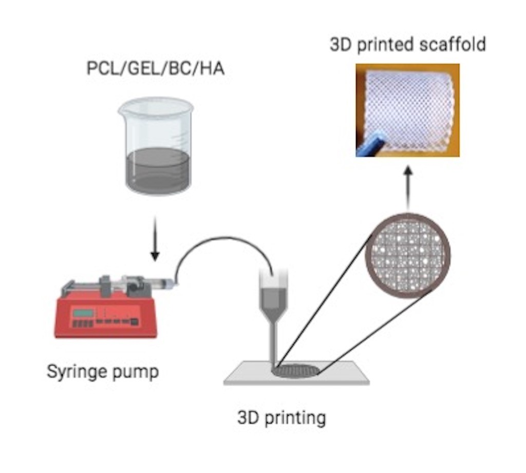
2.2.2. Preparation of Solutions and Production of 3D Printed Scaffolds
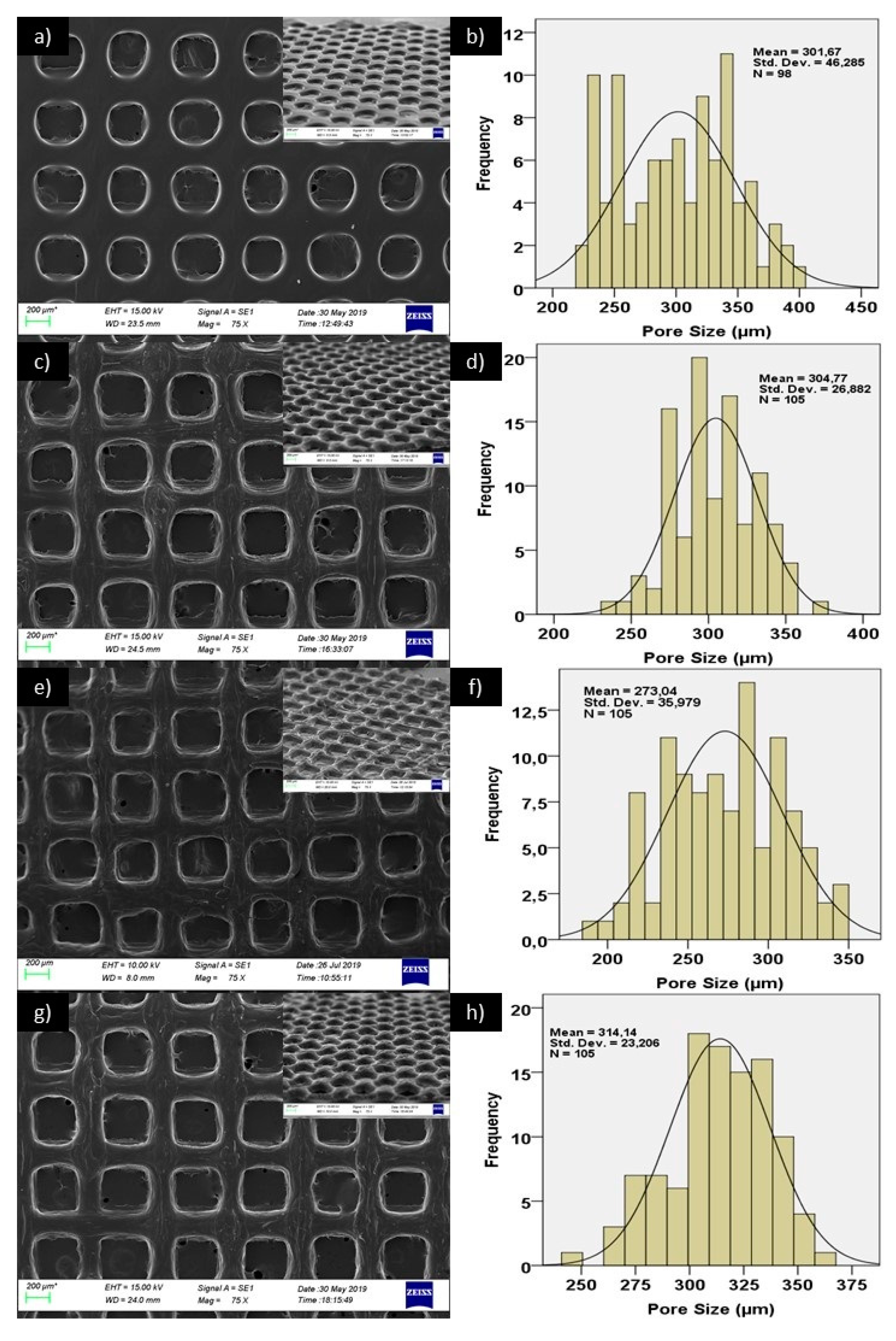
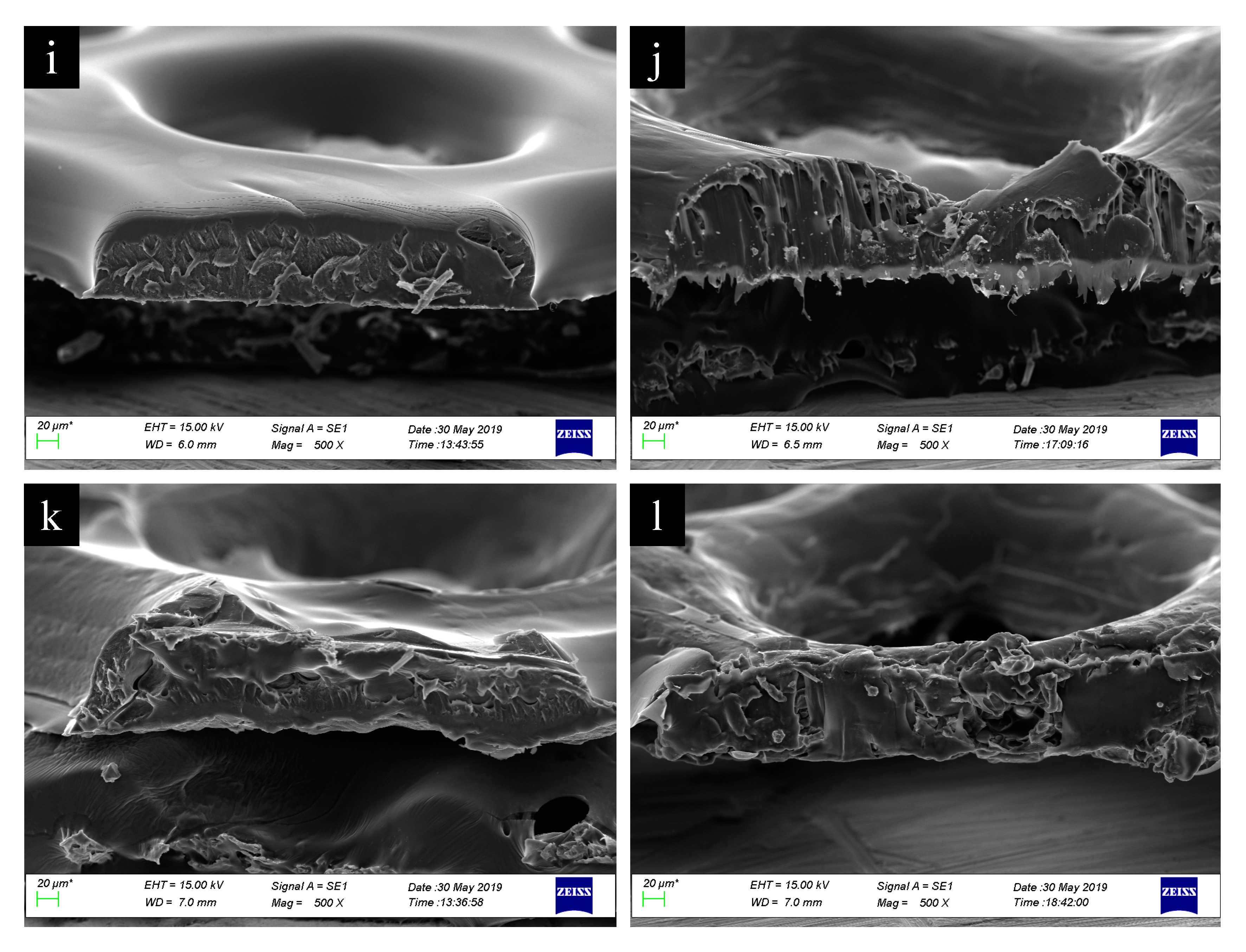
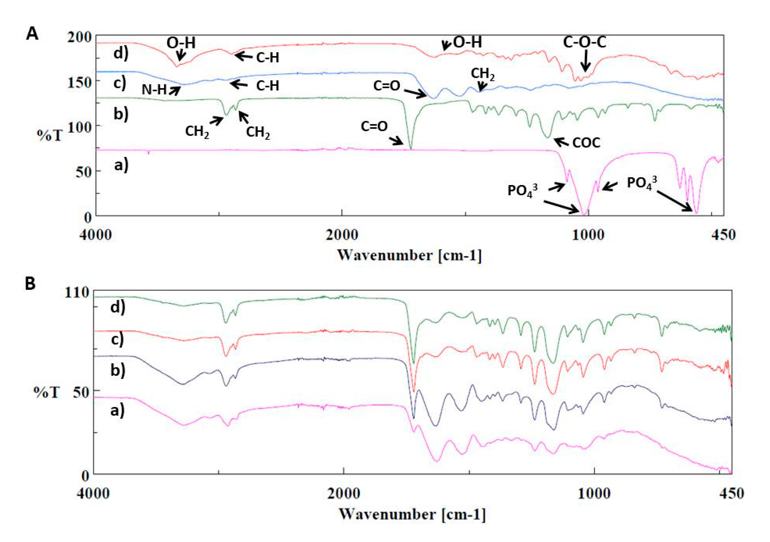
2.2.3. Morphological, Dimensional and Chemical Analysis of 3D Printed Scaffolds
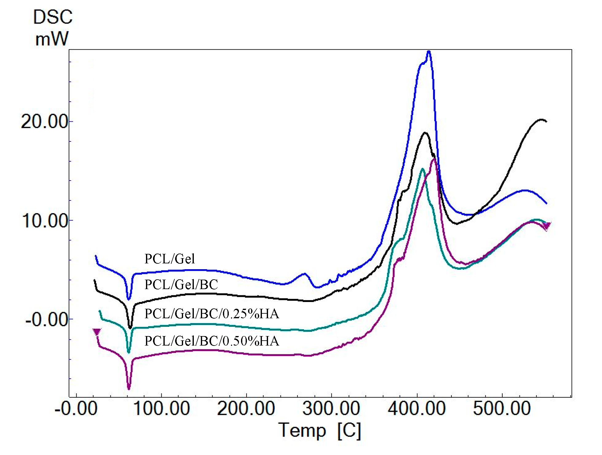
2.2.4. Mechanical and Thermal Analysis of 3D Printed Scaffolds
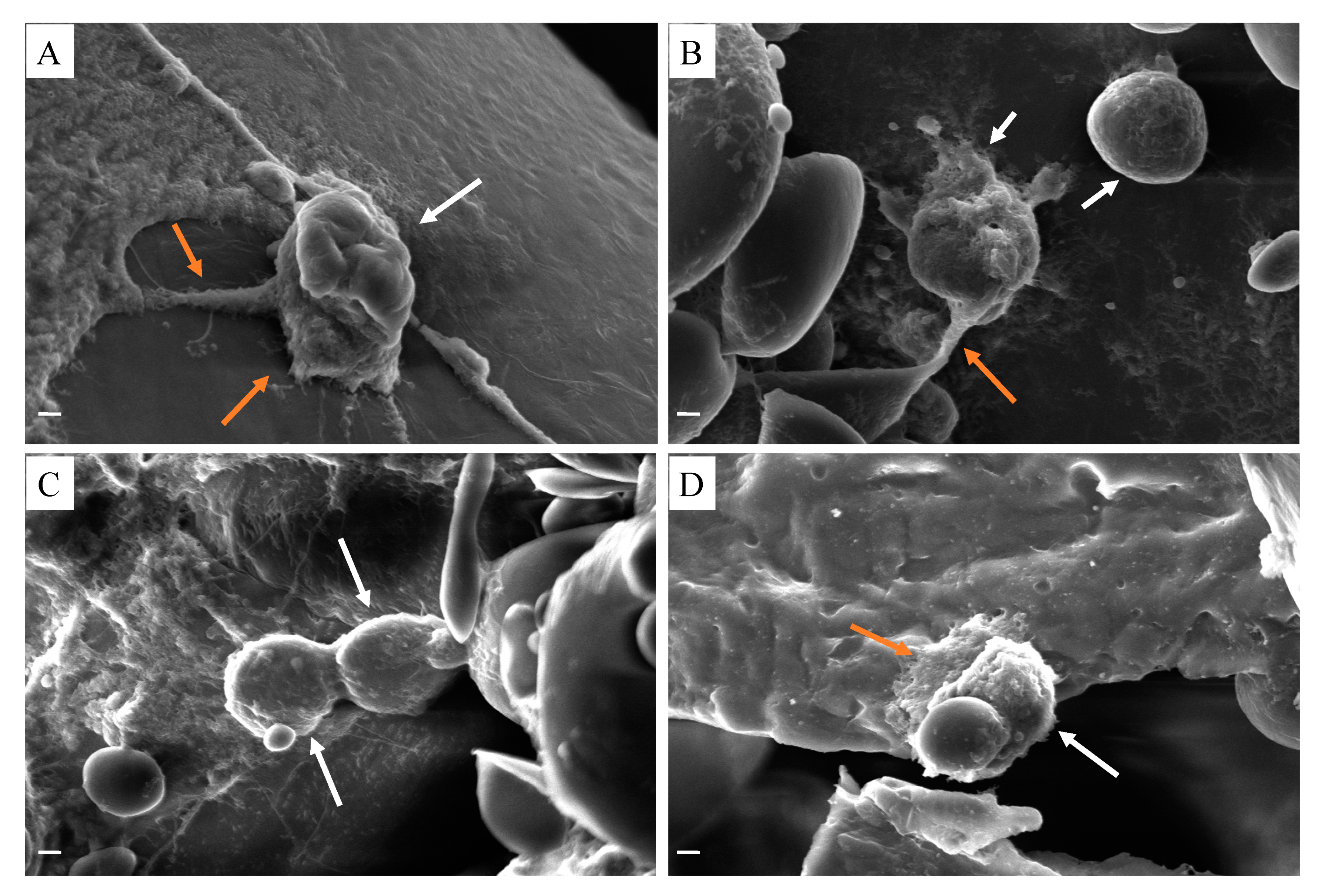
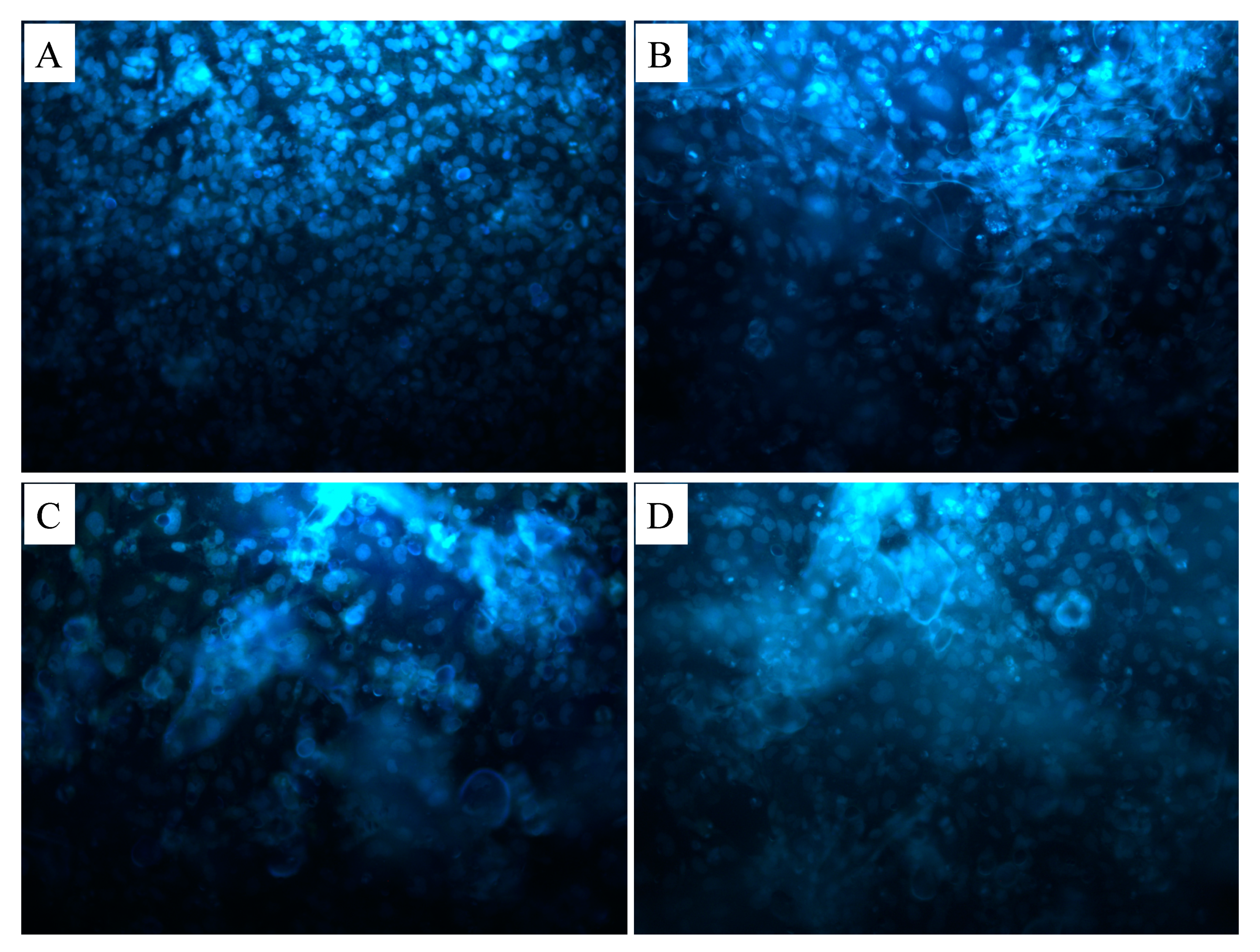
2.2.5. Cell Culture Test for 3D Printed Scaffolds
3. Results and Discussion
4. Conclusions
Author Contributions
Funding
Conflicts of Interest
References
- Langer, R. Biomaterials in drug delivery and tissue engineering: One laboratory’s experience. Acc. Chem. Res. 2000, 33, 94–101. [Google Scholar] [CrossRef] [PubMed]
- Bonassar, L.J.; Vacanti, C.A. Tissue engineering: The first decade and beyond. J. Cell Biochem. 1998, 72, 297–303. [Google Scholar] [CrossRef]
- Atala, A. Tissue engineering and regenerative medicine. Rejuvenation Res. 2019, 7, 235–258. [Google Scholar] [CrossRef]
- Ivkovic, A.; Marijanovic, I.; Hudetz, D.; Porter, R. Regenerative medicine and tissue engineering in orthopaedic surgery. Regen. Orthop. 2011, 3, 923–944. [Google Scholar] [CrossRef]
- Surmenev, R.A.; Shkarina, S.; Syromotina, D.S.; Melnik, E.V.; Shkarin, R.; Selezneva, I.I.; Ermakov, A.M.; Ivlev, S.I.; Cecilia, A.; Weinhardt, V.; et al. Characterization of biomimetic silicate- and strontium-containing hydroxyapatite microparticles embedded in biodegradable electrospun polycaprolactone sca ff olds for bone regeneration. Eur. Polym. J. 2019, 113, 67–77. [Google Scholar] [CrossRef]
- Noh, Y.K.; Costa, A.D.S.D.; Park, Y.S.; Du, P.; Kim, I.-H.; Park, K. Fabrication of bacterial cellulose-collagen composite scaffolds and their osteogenic effect on human mesenchymal stem cells. Carbohydr. Polym. 2019, 219, 210–218. [Google Scholar] [CrossRef]
- Zaborowska, M.; Bodin, A.; Bäckdahl, H.; Popp, J.; Goldstein, A.; Gatenholm, P. Microporous bacterial cellulose as a potential scaffold for bone regeneration. Acta Biomater. 2010, 6, 2540–2547. [Google Scholar] [CrossRef]
- Ramani, D.; Sastry, T.P. Bacterial cellulose-reinforced hydroxyapatite functionalized graphene oxide: A potential osteoinductive composite. Cellulose 2014, 21, 3585–3595. [Google Scholar] [CrossRef]
- Abdelraof, M.; Hasanin, M.S.; Farag, M.M.; Ahmed, H.Y. Green synthesis of bacterial cellulose/bioactive glass nanocomposites: Effect of glass nanoparticles on cellulose yield, biocompatibility and antimicrobial activity. Int. J. Biol. Macromol. 2019, 138, 975–985. [Google Scholar] [CrossRef]
- Huang, Y.; Wang, J.; Yang, F.; Shao, Y.; Zhang, X.; Dai, K. Modification and evaluation of micro-nano structured porous bacterial cellulose scaffold for bone tissue engineering. Mater. Sci. Eng. C 2017, 75, 1034–1041. [Google Scholar] [CrossRef]
- Yin, Y.; Ye, F.; Cui, J.; Zhang, F.; Li, X.; Yao, K. Preparation and characterization of macroporous chitosan–gelatin/β-tricalcium phosphate composite scaffolds for bone tissue engineering. J. Biomed. Mater. Res. 2003, 67, 844–855. [Google Scholar] [CrossRef] [PubMed]
- Su, K.; Wang, C. Recent advances in the use of gelatin in biomedical research. Biotechnol. Lett. 2015, 37, 2139–2145. [Google Scholar] [CrossRef]
- Song, J.-H.; Kim, H.-E.; Kim, H.-W. Production of electrospun gelatin nanofiber by water-based co-solvent approach. J. Mater. Sci. Mater. Med. 2008, 19, 95–102. [Google Scholar] [CrossRef] [PubMed]
- Ma, H.; Feng, C.; Chang, J.; Wu, C. 3D-printed bioceramic scaffolds: From bone tissue engineering to tumor therapy. Acta Biomater. 2018, 79, 37–59. [Google Scholar] [CrossRef] [PubMed]
- Zhang, L.; Yang, G.; Johnson, B.N.; Jia, X. Three-dimensional (3D) printed scaffold and material selection for bone repair. Acta Biomater. 2019, 84, 16–33. [Google Scholar] [CrossRef] [PubMed]
- Turnbull, G.; Clarke, J.; Picard, F.; Riches, P.; Jia, L.; Han, F.; Li, B.; Shu, W. 3D bioactive composite scaffolds for bone tissue engineering. Bioact. Mater. 2018, 3, 278–314. [Google Scholar] [CrossRef] [PubMed] [Green Version]
- Shrivats, A.R.; Mcdermott, M.C.; Hollinger, J.O. Bone tissue engineering: State of the union. Drug Discov. Today 2014, 19, 781–786. [Google Scholar] [CrossRef]
- Paula, A.; Madrid, M.; Paola, A.; Vrech, S.M.; Sanchez, M.A. Advances in additive manufacturing for bone tissue engineering scaffolds. Mater. Sci. Eng. C 2019, 100, 631–644. [Google Scholar] [CrossRef]
- Hutmacher, D.W. Scaffolds in tissue engineering bone and cartilage. Biomaterials 2000, 21, 2529–2543. [Google Scholar] [CrossRef]
- Hestrin, S.; Schramm, M. Synthesis of cellulose by Acetobacter xylinum: 2. Preparation of freeze-dried cells capable of polymerizing glucose to cellulose. Biochem. J. 1953, 58, 345–352. [Google Scholar] [CrossRef] [Green Version]
- Karageorgiou, V.; Kaplan, D. Porosity of 3D biomaterial scaffolds and osteogenesis. Biomaterials 2005, 26, 5474–5491. [Google Scholar] [CrossRef] [PubMed]
- Cyster, L.A.; Grant, D.M.; Howdle, S.M.; Rose, F.R.A.J.; Irvine, D.J.; Freeman, D.; Scotchford, C.A.; Shakesheff, K.M. The influence of dispersant concentration on the pore morphology of hydroxyapatite ceramics for bone tissue engineering. Biomaterials 2005, 26, 697–702. [Google Scholar] [CrossRef]
- Roosa, S.M.M.; Kemppainen, J.M.; Moffitt, E.N.; Krebsbach, P.H.; Hollister, S.J. The pore size of polycaprolactone scaffolds has limited influence on bone regeneration in an in vivo model. J. Biomed. Mater. Res. Part. A 2010, 92, 359–368. [Google Scholar] [CrossRef]
- Andrea, P.; Sossa, F.; Giraldo, B.S.; Clemencia, B.; Garcia, G.; Parra, E.R.; Jose, P.; Arango, A. Comparative study between natural and synthetic Hydroxyapatite: Structural, morphological and bioactivity properties. Rev. Matér. 2018, 23. [Google Scholar] [CrossRef] [Green Version]
- Koutsopoulos, S. Synthesis and characterization of hydroxyapatite crystals: A review study on the analytical methods. J. Biomed. Mater. Res. 2002, 62, 600–612. [Google Scholar] [CrossRef]
- Elzein, T.; Nasser-eddine, M.; Delaite, C.; Bistac, S.; Dumas, P. FTIR study of polycaprolactone chain organization at interfaces. J. Colloid Interface Sci. 2004, 273, 381–387. [Google Scholar] [CrossRef]
- Premlatha, T.S.; Kothai, S. Synthesis, Characterization and Antibacterial Activity of Gelatin-Herb Nanocomposite. Asian J. Biomed. Pharm. Sci. 2015, 5, 2–4. [Google Scholar] [CrossRef]
- Auta, R.; Adamus, G.; Kwiecien, M.; Radecka, I.; Hooley, P. Production and characterization of bacterial cellulose before and after enzymatic hydrolysis. Afr. J. Biotechnol. 2017, 16, 470–482. [Google Scholar] [CrossRef]
- Wang, F.; Shor, L.; Darling, A.; Khalil, S.; Sun, W.; Güçeri, S.; Lau, A. Precision extruding deposition and characterization of cellular polycaprolactone tissue scaffolds. Rapid Prototyp. J. 2004, 10, 42–49. [Google Scholar] [CrossRef] [Green Version]
- Ghorab, D.; Amin, M.; Khowessah, O. Colon-targeted celecoxib-loaded Eudragit S100-coated polycaprolactone microparticles: Preparation, characterization and in vivo evaluation in rats. Drug Deliv. 2011, 18, 523–535. [Google Scholar] [CrossRef]
- Lozano-Sánchez, L.; Bagudanch, I.; Sustaita, A.O.; Iturbe-Ek, J.; Elizalde, L.E.; Garcia-Romeu, L.M.; Elías-Zúñiga, A. Single-Point Incremental Forming of Two Biocompatible Polymers: An Insight into Their Thermal and Structural Properties. Polymers 2018, 10, 391. [Google Scholar] [CrossRef] [Green Version]
- Cervantes, A.L.; Lopez, I.D.; Sanchez, J.D.O.B.; Garcia, A.L.G. Effects of surface texturing on the performance of biocompatible UHMWPE as a bearing material during in vitro lubricated sliding/rolling motion. J. Mech. Behav. Biomed. Mater. 2013, 20, 45–53. [Google Scholar] [CrossRef] [PubMed]
- Khan, R.A.; Parsons, A.J.; Jones, I.A.; Walker, G.S.; Rudd, C.D. Preparation and Characterization of Phosphate Glass Fibers and Fabrication of Poly (caprolactone) Matrix Resorbable Composites. J. Reinf. Plast. Compos. 2010, 29, 1838–1850. [Google Scholar] [CrossRef]
- Asma, C.; Meriem, E.; Mahmoud, B.; Djaafer, B. Physicochemical Characterization of Gelatin-GMC Composite Edibles Films from Polyion-complex Hydrogels. J. Chil. Chem. Soc. 2014, 59, 2279–2283. [Google Scholar] [CrossRef] [Green Version]
- Zhang, Y.; Ouyang, H.; Chwee, T.L.; Ramakrishna, S.; Huang, Z.M. Electrospinning of gelatin fibers and gelatin/PCL composite fibrous scaffolds. J. Biomed. Mater. Res. 2005, 72, 156–165. [Google Scholar] [CrossRef]
- Kim, J.W.; Shin, K.H.; Koh, Y.H.; Hah, M.J.; Moon, J.; Kim, H.E. Production of poly(ε-caprolactone)/hydroxyapatite composite scaffolds with a tailored macro/micro-porous structure, high mechanical properties, and excellent bioactivity. Materials 2017, 10, 1123. [Google Scholar] [CrossRef] [Green Version]
- Zhou, Y.G.; Zou, J.R.; Wu, H.H.; Xu, B.P. Balance between bonding and deposition during fused deposition modeling of polycarbonate and acrylonitrile-butadiene-styrene composites. Polym. Compos. 2020, 41, 60–72. [Google Scholar] [CrossRef]


| Solutions | PCL Conc. (wt %) | GEL Conc. (wt %) | BC Conc. (wt %) | HA Conc. (wt %) |
|---|---|---|---|---|
| PCL/GEL | 14 | 14 | - | - |
| PCL/GEL/BC | 14 | 14 | 0.25 | - |
| PCL/GEL/BC/0.25%HA | 14 | 14 | 0.25 | 0.25 |
| PCL/GEL/BC/0.50%HA | 14 | 14 | 0.25 | 0.50 |
| Parameters | Values |
|---|---|
| Number of Layers | 10 |
| Flow Rate (mL/h) | 0.2 |
| Needle Tip Outer Diameter (mm) | 0.5 |
| Platform Temperature (°C) | 38 |
| Room Temperature (°C) | 25 |
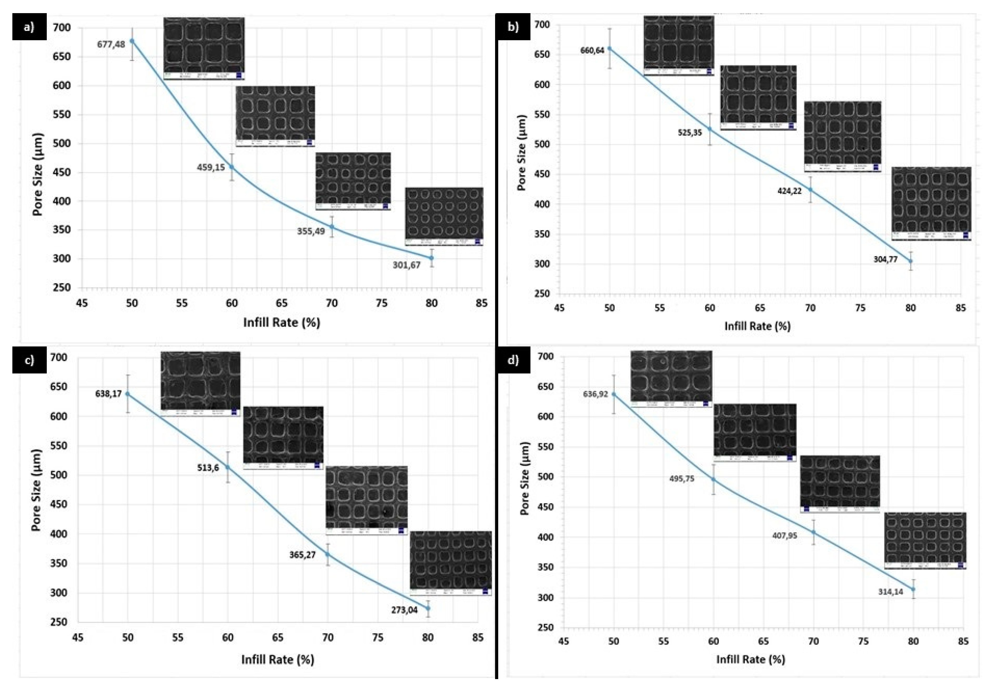
| Infill Rate (%) | 50, 60, 70, and 80 |
| Samples | Tensile Strength (MPa) | Strain at Break (%) |
|---|---|---|
| PCL/GEL | 6.61 ± 1.99 | 4.66 ± 1.75 |
| PCL/GEL/BC | 2.17 ± 0.21 | 5.37 ± 2.33 |
| PCL/GEL/BC/0.25%HA | 1.08 ± 0.34 | 3.29 ± 1.41 |
| PCL/GEL/BC/0.50%HA | 1.58 ± 0.19 | 3.97 ± 2.27 |
© 2020 by the authors. Licensee MDPI, Basel, Switzerland. This article is an open access article distributed under the terms and conditions of the Creative Commons Attribution (CC BY) license (http://creativecommons.org/licenses/by/4.0/).
Share and Cite
Cakmak, A.M.; Unal, S.; Sahin, A.; Oktar, F.N.; Sengor, M.; Ekren, N.; Gunduz, O.; Kalaskar, D.M. 3D Printed Polycaprolactone/Gelatin/Bacterial Cellulose/Hydroxyapatite Composite Scaffold for Bone Tissue Engineering. Polymers 2020, 12, 1962. https://doi.org/10.3390/polym12091962
Cakmak AM, Unal S, Sahin A, Oktar FN, Sengor M, Ekren N, Gunduz O, Kalaskar DM. 3D Printed Polycaprolactone/Gelatin/Bacterial Cellulose/Hydroxyapatite Composite Scaffold for Bone Tissue Engineering. Polymers. 2020; 12(9):1962. https://doi.org/10.3390/polym12091962
Chicago/Turabian StyleCakmak, Abdullah M., Semra Unal, Ali Sahin, Faik N. Oktar, Mustafa Sengor, Nazmi Ekren, Oguzhan Gunduz, and Deepak M. Kalaskar. 2020. "3D Printed Polycaprolactone/Gelatin/Bacterial Cellulose/Hydroxyapatite Composite Scaffold for Bone Tissue Engineering" Polymers 12, no. 9: 1962. https://doi.org/10.3390/polym12091962
APA StyleCakmak, A. M., Unal, S., Sahin, A., Oktar, F. N., Sengor, M., Ekren, N., Gunduz, O., & Kalaskar, D. M. (2020). 3D Printed Polycaprolactone/Gelatin/Bacterial Cellulose/Hydroxyapatite Composite Scaffold for Bone Tissue Engineering. Polymers, 12(9), 1962. https://doi.org/10.3390/polym12091962