Article

Effect of the Activator B(OCH3)3 on the Microstructure and Mechanical Properties of Cu-Mn-Al Alloy Coating via CMT Cladding

1
School of Materials Science and Engineering, North China University of Water Resources and Electric Power, Zhengzhou 450045, China
2
Henan Engineering Research Center on Special Materials and Applications of Water Conservancy and Hydropower Engineering, Zhengzhou 450045, China
3
Henan Key Laboratory of High Performance Carbon Fiber Reinforced Composites, Institute of Carbon Matrix Composites, Henan Academy of Sciences, Zhengzhou 450046, China
4
School of Materials Science and Engineering, Shanghai Jiao Tong University, No. 800, Dong Chuan Road, Shanghai 200240, China
*
Author to whom correspondence should be addressed.
Crystals 2025, 15(10), 881; https://doi.org/10.3390/cryst15100881
Submission received: 26 August 2025 / Revised: 10 October 2025 / Accepted: 11 October 2025 / Published: 13 October 2025

Abstract

This study investigates the fabrication of a Cu-Mn-Al alloy coating on 27SiMn steel using Cold Metal Transfer (CMT) technology with an innovative Ar-B(OCH3)3 mixed shielding gas, focusing on the effect of the gas flow rate (5–20 L/min). The addition of B(OCH3)3 was found to significantly enhance process stability by improving molten pool wettability, resulting in a wider cladding layer (6.565 mm) and smaller wetting angles compared to pure Ar. Macro-morphology analysis identified 10 L/min as the optimal flow rate for achieving a uniform and defect-free coating, while deviations led to oxidation (at low flow) or spatter and turbulence (at high flow). Microstructural characterization revealed that the flow rate critically governs phase evolution, with the primary κI phase transforming from dendritic/granular to petal-like/rod-like morphologies. At higher flow rates (≥15 L/min), increased stirring promoted Fe dilution from the substrate, leading to the formation of Fe-rich intermetallic compounds and distinct spherical Fe phases. Consequently, the cladding layer obtained at 10 L/min exhibited balanced and superior properties, achieving a maximum shear strength of 303.22 MPa and optimal corrosion resistance with a minimum corrosion rate of 0.02935 mm/y. All shear fractures occurred within the cladding layer, demonstrating superior interfacial bonding strength and ductile fracture characteristics. This work provides a systematic guideline for optimizing shielding gas parameters in the CMT cladding of high-performance Cu-Mn-Al alloy coatings.

1. Introduction

27SiMn steel is a representative high-strength low-alloy steel extensively utilized for critical load-bearing components, such as hydraulic support columns in coal mining, owing to its superior mechanical properties [1]. Nevertheless, when servicing in demanding environments with high humidity, salinity, and abrasive conditions, the steel surface is highly susceptible to corrosion and wear damage, which can severely compromise its structural integrity and lead to premature failure [2]. Applying a high-performance coating that offers combined resistance to both corrosion and wear has therefore been recognized as an essential and effective strategy to significantly enhance the durability and extend the service life of 27SiMn steel components [3].
Several coating techniques, such as thermal spraying, laser cladding, and conventional arc welding processes like MIG and Plasma Transferred Arc (PTA), are commonly used for surface protection [4]. However, these methods present certain limitations when depositing copper-based alloys on steel substrates. Thermal spraying often yields coatings with limited adhesive strength and inherent porosity, which can act as initiation sites for corrosion and compromise the coating integrity under mechanical stress [5]. Laser cladding, while capable of producing fine microstructures with low dilution, faces challenges in processing highly reflective materials like copper alloys, leading to process instability and energy inefficiency [6]. Furthermore, the conventional arc welding processes, including MIG and PTA, are characterized by high heat input. This often results in excessive dilution, coarse microstructures, and most critically, the promotion of brittle intermetallic compounds (IMCs) at the coating–substrate interface, which severely undermines the bonding strength and mechanical performance [7,8].
In this context, Cold Metal Transfer (CMT) technology emerges as a superior alternative. As an advanced variant of gas metal arc welding, CMT incorporates a unique “hot-cold-hot” cycle that drastically reduces overall heat input by actively retracting the wire during droplet detachment [9,10]. This fundamental characteristic is key to achieving a cladding layer with low dilution and a refined microstructure. Crucially, the low heat input results in only slight melting of the steel substrate, which significantly limits the inter-diffusion of Fe- and Cu-based alloying elements across the interface. This confined intermixing, in turn, effectively suppresses the extensive formation of brittle IMCs. The capability of CMT for producing high-quality coatings has been validated in prior research. For instance, Qi et al. [11] employed CMT to deposit an S215 aluminum bronze coating on 27SiMn steel, demonstrating a 59.2% reduction in corrosion rate compared to the substrate. Similarly, Liu et al. [12] confirmed the superiority of CMT over conventional MIG welding, producing Inconel 625 coatings with more uniform microstructure and enhanced performance. Furthermore, a comparative study by He et al. [13] revealed that CMT-fabricated Inconel 625 cladding exhibited superior corrosion resistance to its TIG-welded counterpart. The overarching goal of employing CMT deposition in this context is to obtain a high-integrity coating characterized by low dilution, a refined microstructure, excellent metallurgical bonding, and suppressed formation of brittle phases, which collectively contribute to enhanced mechanical properties and superior corrosion resistance.
The selection of the cladding material is equally pivotal for achieving a high-performance protective layer. In this study, a high-manganese aluminum bronze (MAB) alloy wire, designated as BCu74MnAlFeNi, was employed. Cu-Mn-Al alloys from the MAB family are particularly attractive for safeguarding steel components due to their renowned combination of high strength, exceptional wear resistance, and superior corrosion resistance, especially in saline environments akin to mining conditions [14,15]. The effectiveness of MAB coatings is well-documented. For instance, Song et al. [16] demonstrated that MAB coatings deposited via MIG welding exhibited a more uniform microstructure and a notably lower corrosion rate compared to the steel substrate. Furthermore, the utility of these alloys extends to repair applications, as shown by Rahni et al. [17], who reported that MAB plates repaired using a Cu-Mn-Al filler alloy achieved higher tensile and bending strength than those repaired with a Cu-Ni-Al alloy. The specific BCu74MnAlFeNi composition used herein is designed to further enhance these properties; the high Mn content (11.0–14.0 wt%) contributes to solid solution strengthening and stability of the protective surface film, while the addition of Ni and Fe (2.5–4.0 wt%) is known to refine the microstructure and suppress the formation of undesirable brittle phases, thereby improving overall toughness and corrosion performance [18]. Based on these established merits of the MAB system and the optimized composition of the chosen wire, the BCu74MnAlFeNi alloy is posited as an ideal cladding material for significantly enhancing the surface properties of 27SiMn steel.
While the separate benefits of CMT cladding and Cu-Mn-Al alloys are well-appreciated, the composition of the shielding gas—a critical process parameter—offers a significant avenue for further process optimization. The introduction of active agents into the shielding gas is a recognized method to alter arc characteristics and fundamentally improve weld pool behavior, primarily by enhancing surface wetting and fluidity. Trimethyl borate (B(OCH3)3), widely utilized as a catalyst [19], boron source [20], and additive [21,22], has demonstrated its potential in surface engineering. For example, it has been successfully applied as a vapor-phase boronizing agent for iron substrates [23] and as a precursor in wear-resistant coatings for tools [24]. Despite its versatility and known efficacy in these domains, its application as an active additive in the shielding gas for arc cladding processes remains largely unexplored. Consequently, a critical research gap exists: the systematic investigation into the effects of B(OCH3)3 on the CMT cladding process of Cu-Mn-Al alloys, and how its introduction (particularly as a function of flow rate) governs the resultant microstructure, mechanical properties, and corrosion resistance, has not been previously reported. Filling this gap is essential to fully leverage the potential of active shielding gases for producing superior coatings.
To address this research gap, the present study systematically investigates the CMT cladding of a BCu74MnAlFeNi high-manganese aluminum bronze coating onto 27SiMn steel using an Ar-B(OCH3)3 mixed shielding gas. The primary focus is placed on elucidating the influence of the mixed gas flow rate on the microstructure evolution, shear strength, and electrochemical corrosion behavior of the coatings. The novelty of this work is twofold: (1) it pioneers the application of B(OCH3)3 as an active agent in the shielding gas for the CMT cladding of Cu-Mn-Al alloys, and (2) it establishes a quantitative correlation between the gas flow rate and the key performance metrics, thereby identifying an optimal processing parameter. The findings are anticipated to provide crucial theoretical insights and practical guidance for the industrial fabrication of high-performance, durable protective coatings.

2. Experimental Design

2.1. Experimental Materials

The substrate material consisted of 27SiMn steel plates (300 mm × 200 mm × 20 mm). The cladding wire was BCu74MnAlFeNi high-manganese aluminum bronze (1.2 mm diameter). The chemical compositions of both substrate and cladding materials are detailed in Table 1 [2]. The chemical composition of the BCu74MnAlFeNi wire was provided by the supplier and is consistent with its specification.
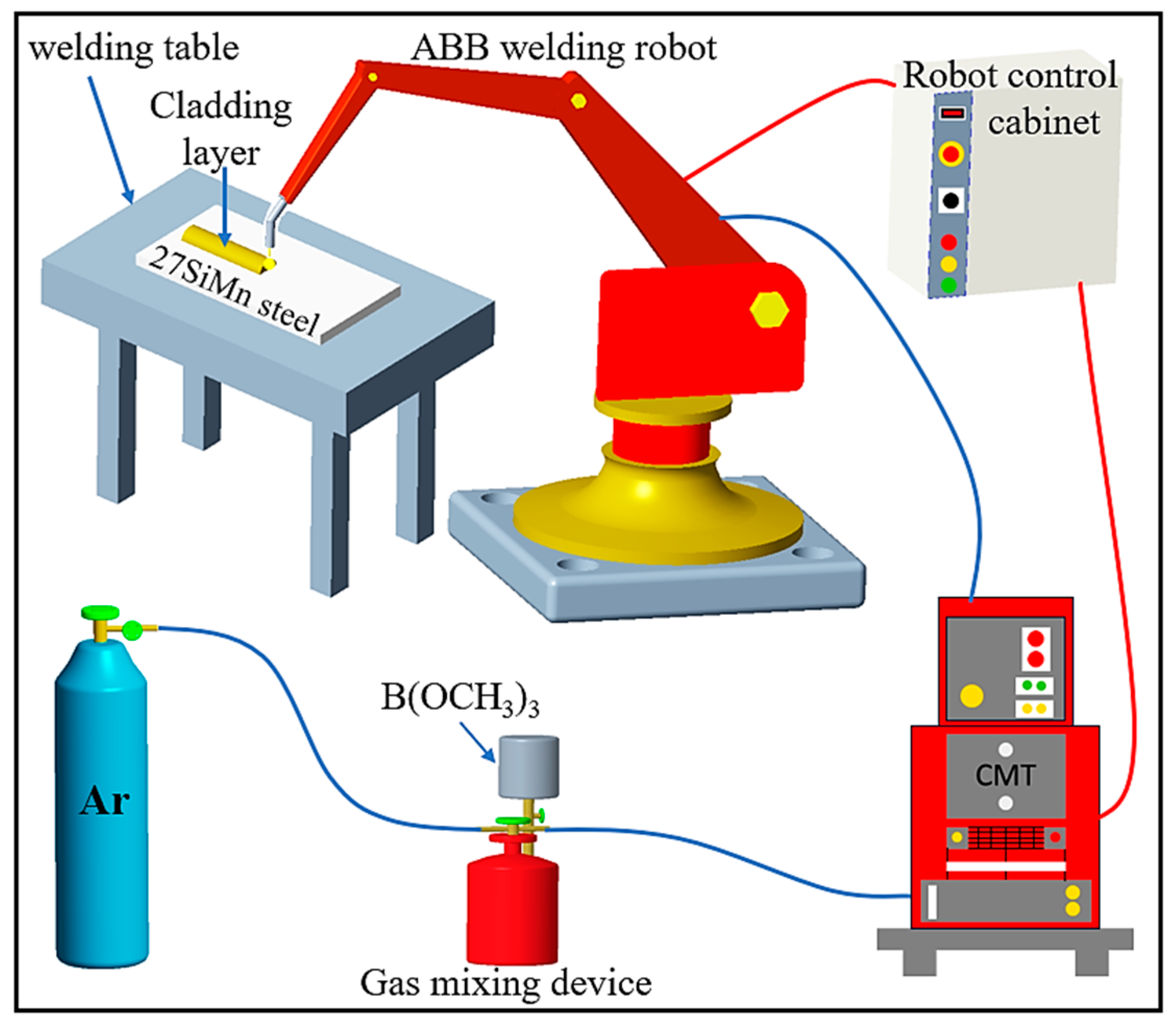
An Ar-B(OCH3)3 mixed shielding gas was employed during the cladding process. Trimethyl borate (B(OCH3)3), a colorless and volatile liquid at room temperature, served as the source of the active gas. The gas mixture was prepared using a specialized Xinrui flux generator (model XRHF-160C, Zhejiang Xinrui Brazing Technology Co., Ltd., Shaoxing, China), as shown in Figure 1a. In this setup, liquid B(OCH3)3 was first placed in the generator’s container. High-purity argon (Ar, purity ≥ 99.99%) was then bubbled through the liquid at a controlled flow rate. The saturated argon vapor, carrying B(OCH3)3 vapor, constituted the final Ar-B(OCH3)3 mixture delivered to the welding torch. The entire gas delivery system was designed to ensure a stable and homogeneous mixture.

2.2. Cladding Procedure and Sample Preparation

The substrate material, 27SiMn steel, was precisely sectioned into 150 mm × 40 mm × 20 mm specimens using CNC wire electrical discharge machining prior to the cladding process. The surfaces designated for cladding were mechanically ground to eliminate oxides and subsequently cleaned with anhydrous ethanol to ensure a pristine surface. The Cu-Mn-Al alloy cladding process was performed using the Cold Metal Transfer (CMT) welding system illustrated in Figure 1b. This integrated system comprises an ABB IRB1400 six-axis robot (Acea Brown Boveri (ABB), Zurich, Switzerland), a VR−7000 CMT wire feeding system (Fronius, Wels, Austria), a robot control cabinet, and a welding power source. The Ar-B(OCH3)3 mixed shielding gas, prepared by the flux generator described in Section 2.1, was supplied to the torch. The connection diagram between the CMT welding system and the flux generator is shown in Figure 2. The specific CMT process parameters used to investigate the effect of the mixed gas flow rate are summarized in Table 2.
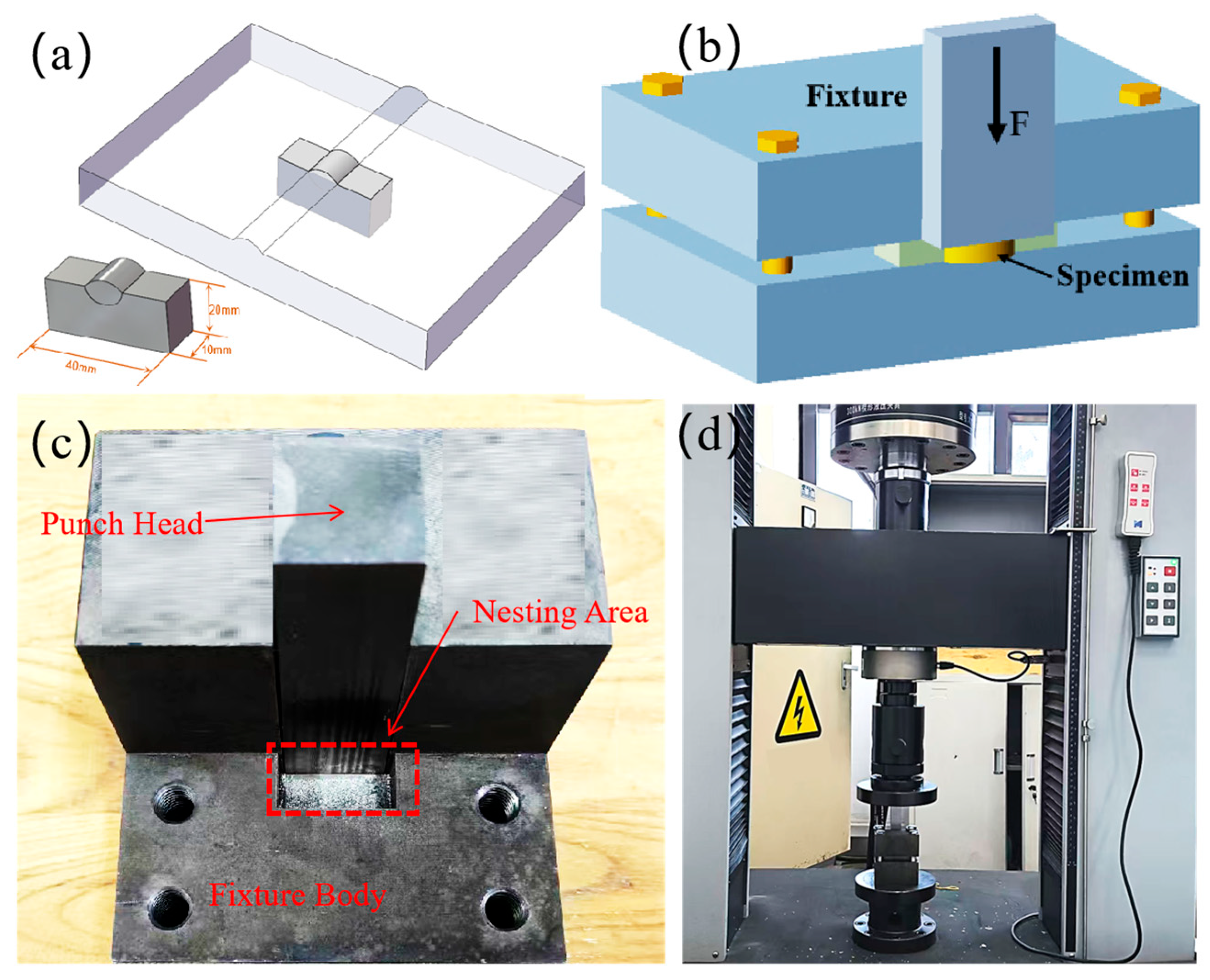
After the cladding process, the coated plates were sectioned perpendicular to the welding direction using a wire electrical discharge machining (EDM) (model DK7720, Jiangsu Sanlin Technology Equipment Co., Ltd., Yangzhou, China) system to obtain cross-sectional metallographic specimens with dimensions of 40 mm × 20 mm × 10 mm, as typically illustrated in Figure 3a. The specimens were then sequentially ground with SiC papers (240–1500 grit) and polished with 3 μm diamond paste to achieve a mirror-like surface. To reveal the microstructure, different etchants were applied due to the distinct chemical compositions of the materials. The 27SiMn steel substrate was etched using a solution of 4% HNO3 + 4 mL HF + 92 mL H2O for approximately 10 s. Conversely, the Cu-Mn-Al cladding layer was etched with a solution of 1 g FeCl3 + 10 mL concentrated HCl + 20 mL ethanol for approximately 20 s.

2.3. Microstructure and Performance Analysis

Microstructural morphology and elemental distribution were investigated using a Helios 5CX field-emission Scanning Electron Microscope (SEM) (Thermo Fisher Scientific, Waltham, MA, USA) coupled with Energy-Dispersive X-ray Spectroscopy (EDS). The EDS analysis was focused on key microstructural features and the cladding–substrate interface region. The phase composition of the Cu-Mn-Al cladding layer was determined by X-ray Diffraction (XRD) (Dandong Haoyuan Instrument Co., Ltd., Dandong, China) using a DX-2700BH diffractometer with Cu Kα radiation (λ = 1.54056 A). The XRD measurements were conducted over a 20 scanning range from 20° to 90° with a step size of 0.02 and a scan rate of 10 °/min, operating at 40 kV and 40 mA.
The interfacial bonding strength between the Cu-Mn-Al cladding layer and the 27SiMn substrate was evaluated via shear testing on a universal testing machine. Test blocks (10 mm × 5 mm × 5 mm) were precisely sectioned from the 40 mm × 20 mm × 10 mm metallographic specimens using EDM. A custom-designed shear fixture was employed for the test, which was conducted using a universal testing machine, shown in Figure 3b,d, which schematically illustrates the shear test setup, where the sample was mounted in the fixture such that the shear force (F) was applied strictly parallel to the cladding substrate interface. Figure 3c shows a photograph of the custom-designed fixture, highlighting the punch head and nesting area. The test was executed at a constant crosshead speed of 0.5 mm/min. For each mixed gas flow rate condition, three replicate tests were performed to ensure statistical reliability, and the averaged shear strength was recorded. The resulting fracture surfaces were subsequently examined using SEM to determine the failure mechanism.
Electrochemical measurements were performed using a Corrtest CS310M (Corrtest, Wuhan, China) workstation in a 3.5 wt% NaCl solution to assess the corrosion resistance. A standard three-electrode system was employed, consisting of the cladding sample as the working electrode, a saturated calomel electrode (SCE) as the reference electrode, and a platinum sheet as the counter electrode. The exposed working area was fixed at 0.5 cm2 using an O-ring. Before the tests, the working electrode was polarized at −0.6 V for 5 min for surface stabilization. The Open Circuit Potential (OCP) was monitored for 30 min. Linear Polarization Resistance (LPR) and corrosion current density (Icorr) were determined by scanning from −0.6 V (initial) to 0.4 V (final) at a scan rate of 1 mV/s.

3. Results and Discussion

3.1. Effect of Mixed Gas Flow Rate on the Microstructure of the Cladding Layer

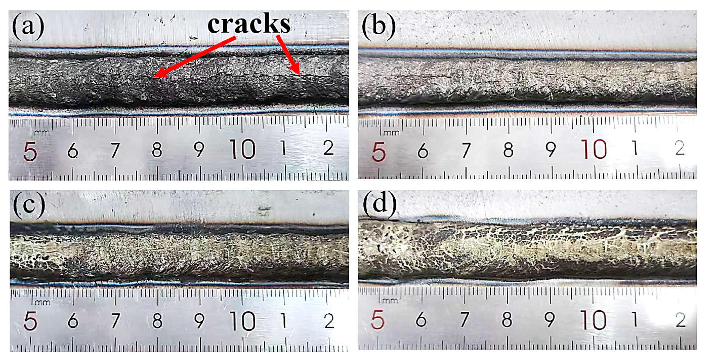
The macroscopic morphology and formation behavior of the cladding layer are critically influenced by the dynamics of the shielding gas. Figure 4 presents the surface morphologies of the cladding layers deposited at mixed gas flow rates ranging from 5 to 20 L/min.
At a low flow rate of 5 L/min (Figure 4a), the cladding layer exhibits a continuous but non-uniform appearance. A darker surface coloration and visible oxide discoloration along the edges suggest that the shielding atmosphere was insufficient to fully protect the molten Cu-Mn-Al alloy from atmospheric oxygen, leading to mild oxidation. The most superior surface morphology was achieved at a flow rate of 10 L/min (Figure 4b). The clad layer appears uniform, smooth, and bright, with a consistent width and a clean surface free from significant oxidation or spatter. This indicates that the gas flow rate provided an optimal balance, ensuring both effective shielding from the atmosphere and a stable, tranquil molten pool, which promoted excellent wetting and spreading on the steel substrate. When the flow rate was increased to 15 L/min (Figure 4c), the surface quality began to deteriorate. Minor spatter particles are observable adjacent to the main clad track, and the surface finish becomes slightly less smooth. This suggests that the increased gas momentum started to cause mild turbulence, disturbing the droplet transfer and the stability of the molten pool. At the highest flow rate of 20 L/min (Figure 4d), the clad layer shows a visibly rough and irregular surface, accompanied by severe spatter. The excessive gas flow likely induced strong turbulence in the molten pool and deflected the arc, leading to an unstable deposition process.
In summary, the macro-morphology evolution clearly demonstrates that the mixed gas flow rate has a profound impact on the cladding quality. The optimal flow rate of 10 L/min yields a defect-free, smooth, and well-formed clad layer, while deviations from this value result in issues ranging from oxidation (at low flow) to spatter and turbulence (at high flow).
Beyond the flow rate, the composition of the shielding gas itself is a fundamental factor governing molten pool behavior. To isolate the effect of the active agent, comparative cladding experiments were conducted with pure Ar and an Ar + B(OCH3)3 mixture at a fixed flow rate of 10 L/min. The resulting wetting angles and layer widths are summarized in Figure 5. The data clearly show that the inclusion of B(OCH3)3 significantly improves wettability. The wetting angles decreased from 70.42°/79.49° to 69.99°/60.96°, while the cladding layer width increased from 4.937 mm to 6.565 mm. These results demonstrate that B(OCH3)3 enhances the fluidity and spreading behavior of the Cu-Mn-Al alloy during CMT deposition, thereby promoting the formation of a wider and more uniform cladding layer.
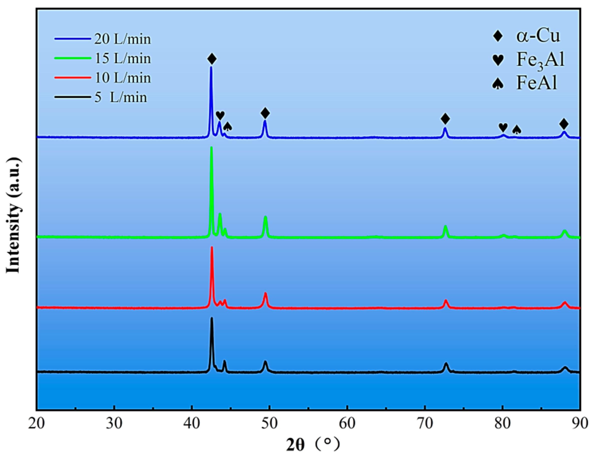
The influence of the gas flow rate on the phase composition was investigated by XRD. Figure 6 shows the diffraction patterns of the cladding layers fabricated under different flow rates. A comparative analysis reveals that while the identified phases are consistent, their relative contents are significantly influenced by the flow rate.
The intensity of the primary α-Cu peaks (e.g., at 2θ ≈ 43.5° and 50.5°) exhibits a clear non-monotonic trend. The intensity increases as the gas flow rate rises from 5 L/min to 15 L/min, reaching its maximum at 15 L/min, and then slightly decreases at 20 L/min. This suggests that a moderate increase in gas flow rate promotes the formation of a well-crystallized α-Cu matrix, likely due to improved arc stability and more efficient degassing. The subsequent decrease at 20 L/min is likely due to excessive turbulence disrupting the solidification front.
Conversely, the peak corresponding to the Fe3Al phase (e.g., at 2θ ≈ 81°) is nearly undetectable at 5 L/min but becomes distinctly visible and strengthens at 15 L/min and 20 L/min. This provides direct evidence that higher gas flow rates intensify molten pool stirring, enhancing the dissolution of Fe from the steel substrate and promoting the formation of Fe3Al and other Fe-Al intermetallic compounds.
In summary, the XRD analysis reveals a competing effect: the gas flow rate simultaneously enhances the crystallinity of the α-Cu matrix up to a point (15 L/min) while steadily increasing Fe dilution and the abundance of Fe-rich intermetallic phases. The flow rate of 10 L/min, identified as optimal for macro-morphology and mechanical properties, likely represents a balance between these two competing factors.
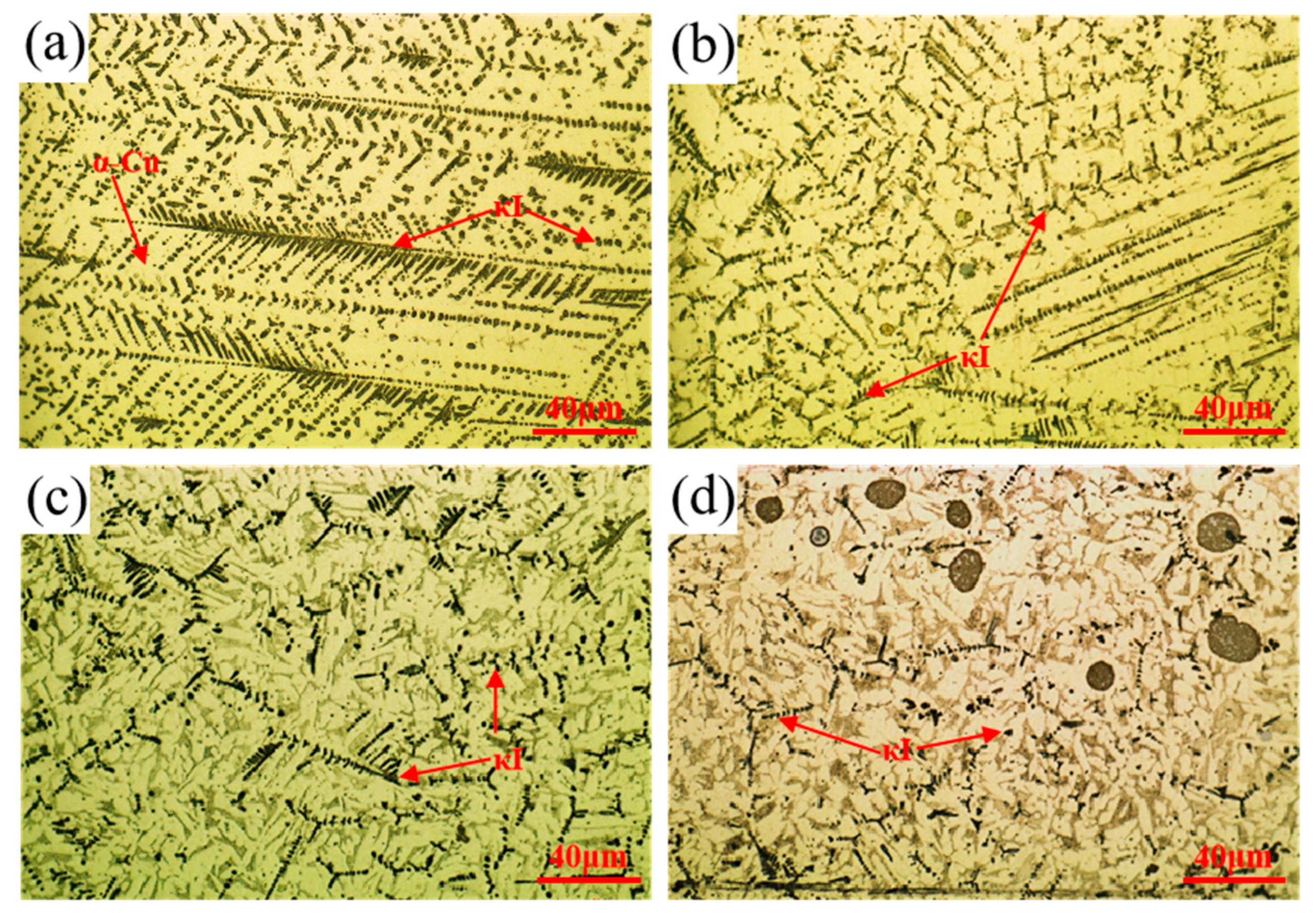
The corresponding microstructural evolution under different gas flow rates is shown in Figure 7. At 5 L/min, the structure contains dense granular and long dendritic κI phases within the α-Cu matrix. As the flow rate increases to 10 L/min and 15 L/min, the κI phases transition to petal-like and rod-like morphologies with reduced density, and light gray lamellar phases appear. At 20 L/min, distinct dark black spherical Fe-rich phases (originating from the substrate due to intense stirring) are observed alongside the κI and lamellar phases.
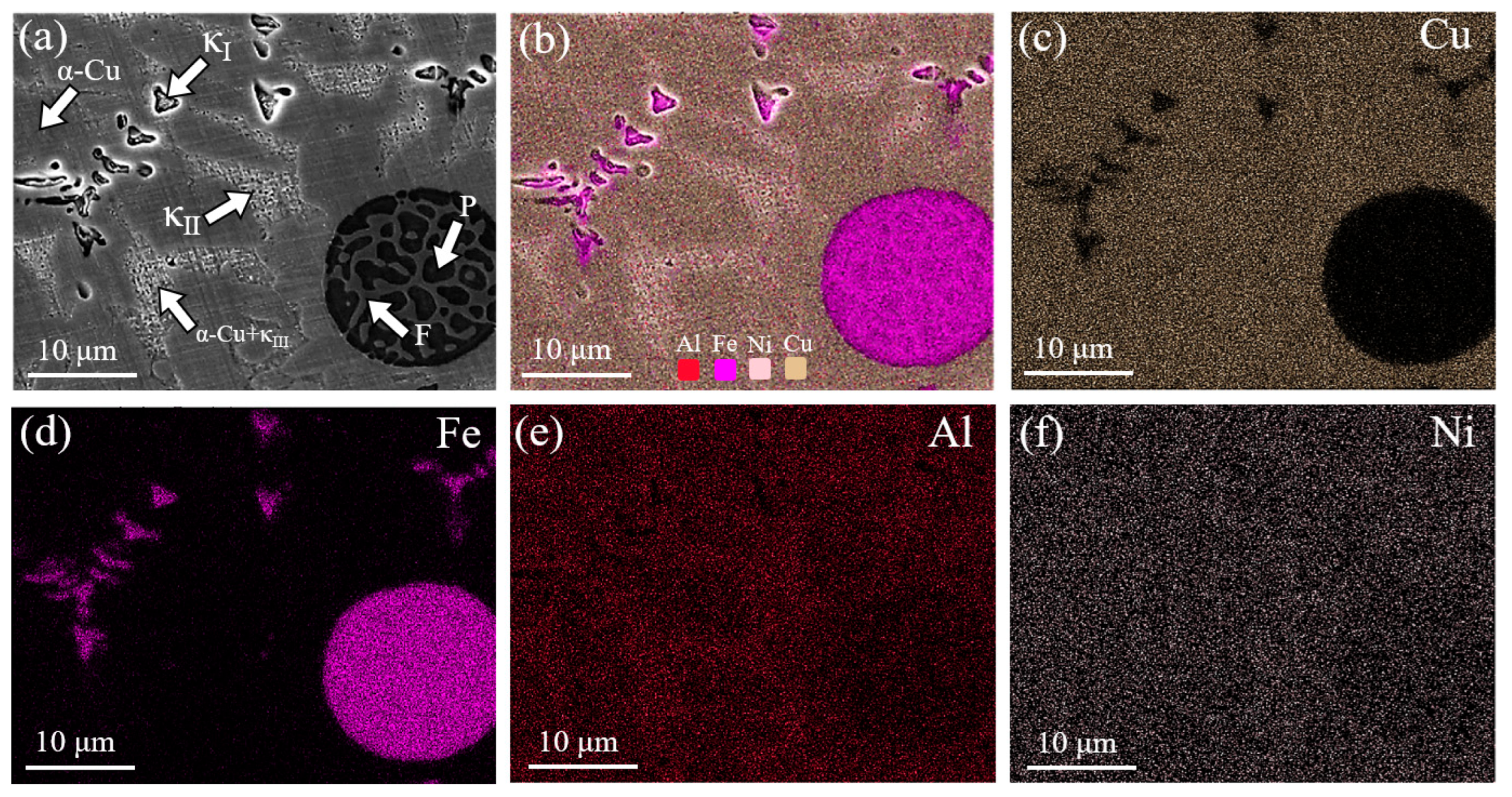
To analyze the light gray lamellar and dark black spherical phases, EDS mapping was conducted in their respective regions, with results shown in Figure 8. The SEM image in Figure 8a shows the dark black spherical phase consisting of light gray and dark black phases. Figure 8b reveals significant Fe and Mn enrichment in the dark black spherical phase. The elemental distribution suggests the dark black spherical phase originates from the 27SiMn steel substrate. This phase forms due to increased molten pool stirring at higher gas flow rates, enabling 27SiMn steel droplet incorporation into the cladding. Liquid phase separation occurs between Cu and 27SiMn steel droplets, forming the dark black spherical phase. When cooling to room temperature, the white ferrite (F) and black pearlite (P) formed.
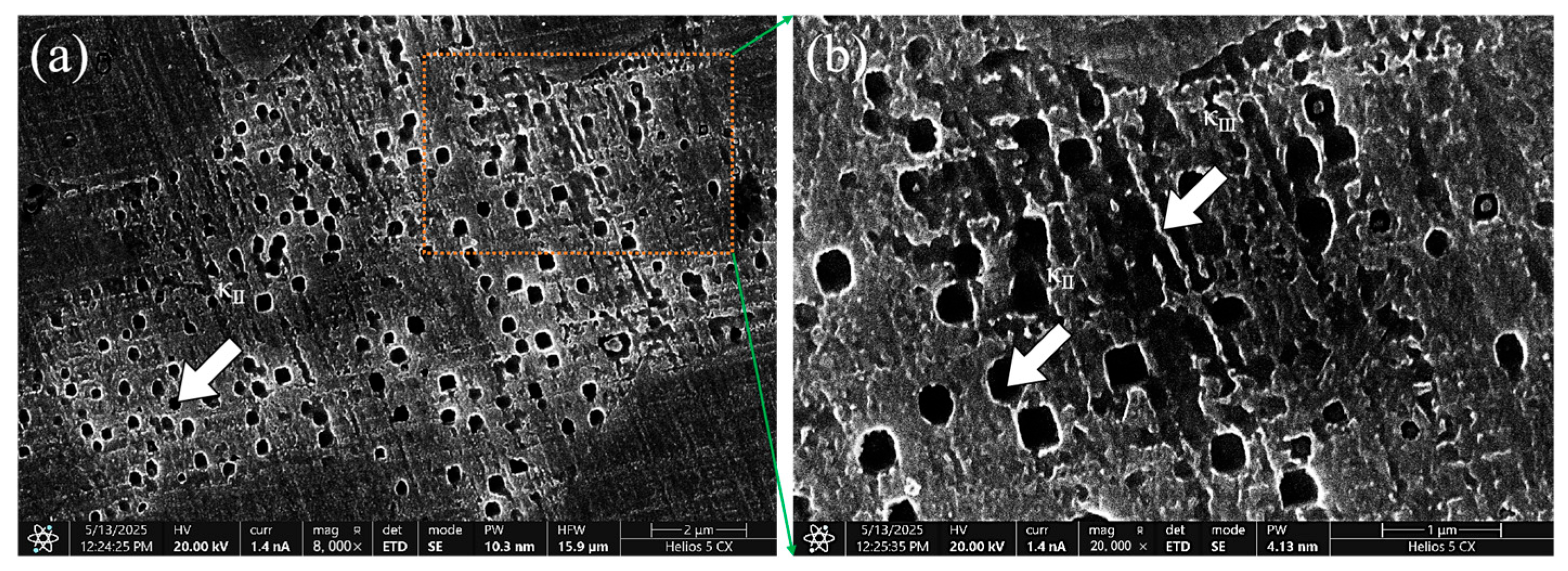
Figure 9 reveals that the light gray lamellar phase consists of both spherical and lamellar structures at higher magnification. Based on elemental and morphological analysis, the lamellar phase is identified as the NiAl-rich κIII phase, with spherical κII phase precipitating in the eutectoid (α-Cu + κIII) matrix.
However, it is noteworthy that no β/β′ phases or γ2 phases were observed in the Cu-Mn-Al alloy cladding layer in this experiment, which is similar to the results of phase analysis on additively manufactured aluminum bronze alloys by GMAW reported by Xu et al. [25]. This may be attributed to the fact that the relatively high cooling rate of CMT inhibits the formation of β/β′ (Cu3Al) phases. Meanwhile, the relatively high contents of Ni and Mn elements in the Cu-Mn-Al alloy suppress the formation of γ2 (Cu9Al4) phases [26,27].

3.2. Effect of Mixed Gas Flow Rate on Cladding Layer Properties

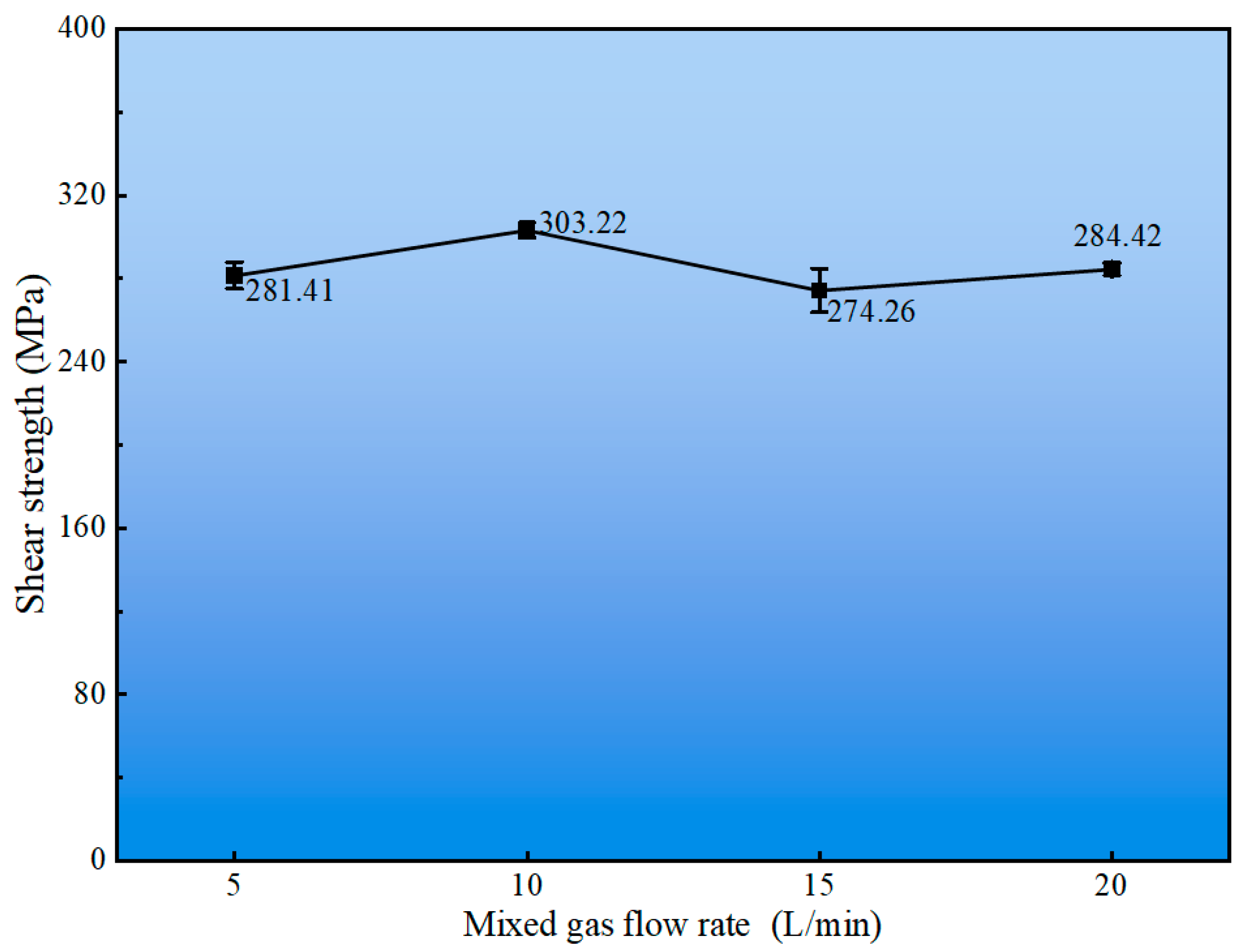
The integrity of the interfacial bond between the Cu-Mn-Al cladding layer and the 27SiMn steel substrate was quantitatively evaluated through shear testing. As summarized in Figure 10, the shear strength of the cladding layer demonstrates a clear dependence on the mixed gas flow rate, exhibiting a non-monotonic trend. A maximum strength of 303.22 MPa was achieved at the flow rate of 10 L/min, whereas a minimum value of 274.26 MPa was recorded at 15 L/min. This optimal performance at 10 L/min aligns with the prior observations of superior macro-morphology and process stability at this parameter.
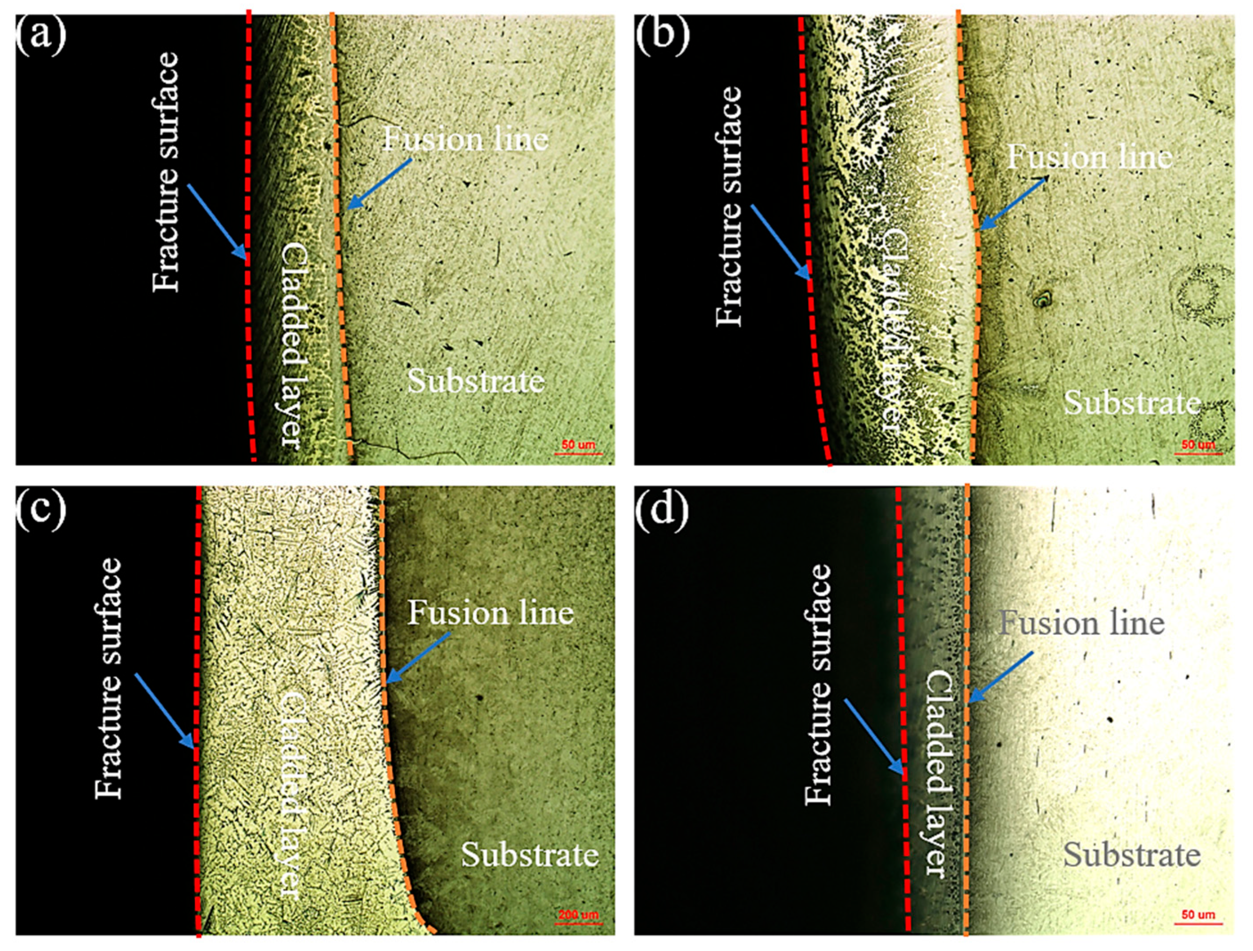
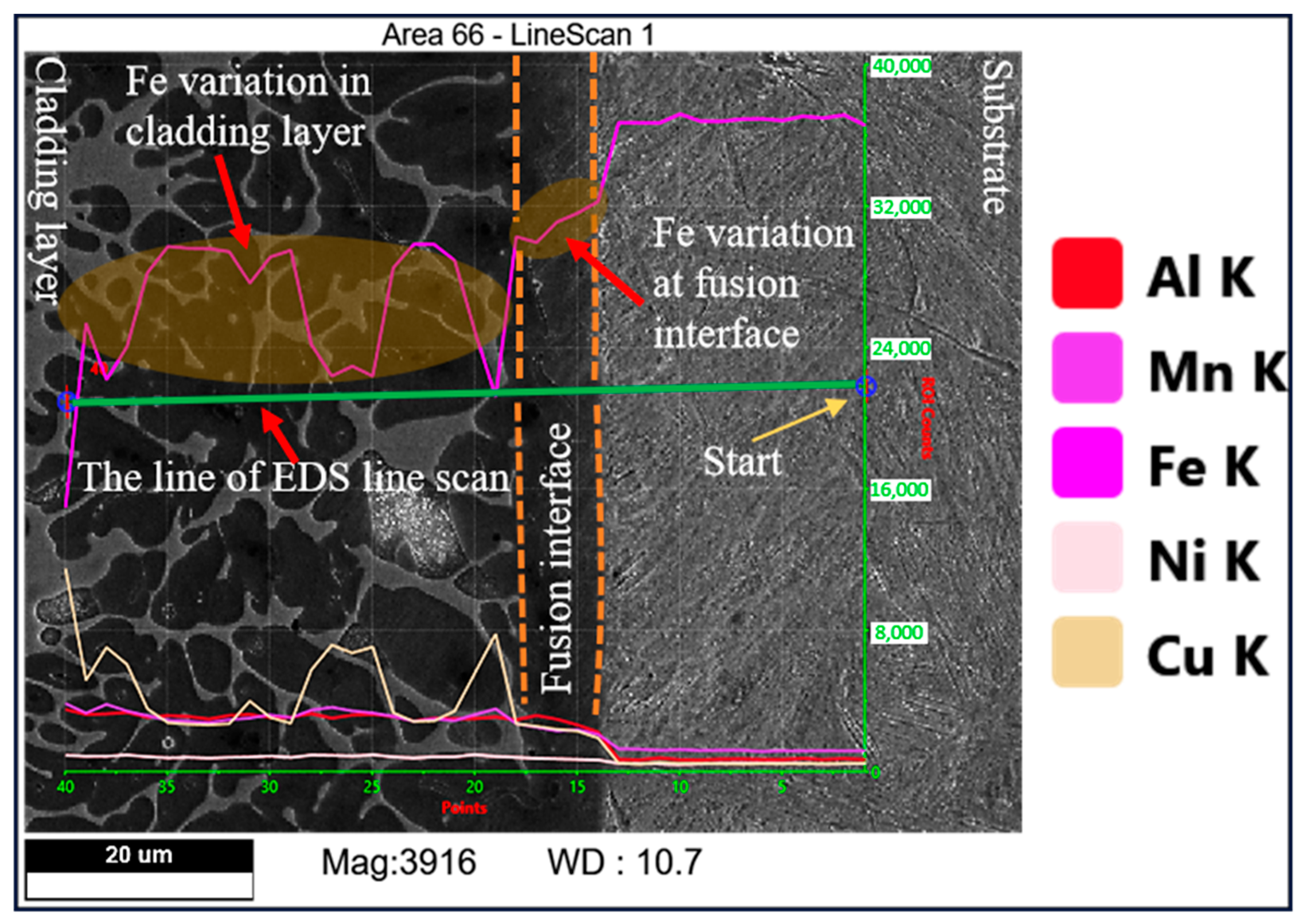
A critical finding is revealed in the optical micrographs of the shear fracture paths (Figure 11a–d). In all cases, the fracture propagated exclusively within the Cu-Mn-Al cladding layer, never along the cladding–substrate interface. This consistent failure location provides direct evidence that the metallurgical bonding strength at the fusion interface exceeds the cohesive strength of the cladding alloy itself. The mechanism behind this superior interfacial strength was elucidated by EDS line scanning analysis (Figure 12). The results show a pronounced enrichment of Fe at the fusion interface, resulting from controlled diffusion from the steel substrate during the low-heat-input CMT process. This localized Fe enrichment induces a solid solution strengthening effect at the interface, making it stronger than the cladding layer and thereby dictating the failure path to remain within the clad material.
Scanning Electron Microscopy (SEM) was employed to analyze the fracture surfaces and identify the underlying failure mechanism. As shown in Figure 13, the fracture surfaces for all gas flow rates are characterized by a high density of dimples of varying sizes. This dimpled morphology is the hallmark of microvoid coalescence, confirming that the Cu-Mn-Al cladding layer fails via a ductile fracture mechanism under shear loading. The presence of this feature across all tested parameters indicates that the cladding material possesses good toughness, which is a desirable property for a protective coating subjected to mechanical stress.
The Tafel curves of the substrate and the cladding layers, measured under varying mixed gas flow rates, were obtained using an electrochemical workstation (Figure 14). The Tafel curves were fitted using CS Analysis software (version 6.4) to determine the corrosion current densities (Icorr) and corrosion rates of both the cladding layers and the substrate at different mixed gas flow rates. The corresponding fitting results, summarized in Figure 15, demonstrate that both the corrosion current density (Icorr) and corrosion rate exhibit similar variation trends with increasing mixed gas flow rate. At a mixed gas flow rate of 10 L/min, the cladding layer exhibits minimum values of 3.2842 × 10⁻⁶ A·cm−2 for Icorr and 0.02935 mm/y for corrosion rate. Conversely, at 15 L/min, maximum values of 3.032 × 10⁻⁵ A·cm−2 (Icorr) and 0.27099 mm/y (corrosion rate) were observed. These results indicate that the cladding layer achieves optimal corrosion resistance at a flow rate of 10 L/min. Notably, the substrate consistently demonstrated higher Icorr and corrosion rate values compared to the cladding layer. Consequently, the Cu-Mn-Al alloy cladding layer exhibits superior corrosion resistance to the base metal, confirming that the cladding process effectively enhances corrosion protection.

4. Conclusions

In this study, a high-manganese aluminum bronze (Cu-Mn-Al) coating was successfully fabricated on 27SiMn steel using Cold Metal Transfer (CMT) technology with an Ar-B(OCH3)3 mixed shielding gas. The systematic investigation into the effects of the mixed gas flow rate yields the following main conclusions:
(1)
The mixed gas flow rate critically governs the microstructure evolution. As the flow rate increases from 5 to 20 L/min, the morphology of the primary κI phase evolves from dendritic and granular to petal-like and rod-like configurations. At higher flow rates (15–20 L/min), the cladding layer develops light gray eutectoid structures (α-Cu + κIII phase) and spherical κII phases. Notably, distinct dark spherical Fe-rich phases, originating from the intensified stirring and incorporation of the steel substrate, are prominently observed at 20 L/min.
(2)
An optimal gas flow rate of 10 L/min was identified, achieving a balance between effective shielding and molten pool stability. Under this condition, the cladding layer attains its peak shear strength of 303.22 MPa. The consistent occurrence of shear fractures within the cladding layer itself, characterized by dimpled ductile fracture surfaces, unequivocally demonstrates that the interfacial bonding strength surpasses the cohesive strength of the Cu-Mn-Al alloy.
(3)
The cladding layer deposited at 10 L/min also exhibits superior corrosion resistance in a 3.5 wt% NaCl solution, demonstrating the lowest corrosion current density (3.2842 × 10⁻⁶ A·cm−2) and corrosion rate (0.02935 mm/y). Furthermore, all cladding layers provided significantly better corrosion protection than the uncoated 27SiMn steel substrate.
(4)
The incorporation of B(OCH3)3 as an active agent in the shielding gas fundamentally improves the deposition process. It significantly enhances the wettability of the Cu-Mn-Al alloy, resulting in a smaller wetting angle and a wider, more uniform cladding layer compared to using pure argon.

Author Contributions

Conceptualization, J.P.; methodology, J.P.; validation, J.P., S.X. and J.X.; formal analysis, S.X. and J.X.; investigation, J.P., S.X. and J.X.; resources, J.P., X.W., N.C. and P.W.; data curation, J.P., S.X. and J.X.; writing—original draft preparation, S.X. and J.X.; writing—review and editing, J.P., N.C., X.W. and Z.N.; visualization, S.X. and J.X.; supervision, J.P.; project administration, J.P.; funding acquisition, J.P. All authors have read and agreed to the published version of the manuscript.

Funding

This work was supported by the Key Scientific Research Projects of Higher Education Institutions in Henan Province (No. 24A460017), Key R & D and Promotion Project of the Henan Province (Science and Technology Research) (No. 252102220064), Key R & D and Promotion Project of the Henan Province (Science and Technology Research) (No. 252102220078). The authors thank for the special funding and equipment support of the visiting professor at the School of Materials Science and Engineering.

Data Availability Statement

The original contributions presented in the study are included in the article, further inquiries can be directed to the corresponding author.

Conflicts of Interest

The authors declare no conflicts of interest.

References

  1. Zhang, C.; Kang, J.; Shu, L.; Xing, Z.; Wang, H. Study on the Low-Cycle Fatigue Performance and Failure Behavior of IN718 Coatings Laser Cladded on the Surface of 27SiMn Steel. Eng. Fail. Anal. 2025, 174, 109537. [Google Scholar] [CrossRef]
  2. Li, C.; Ni, Y.; Wang, M.; Lu, Z.; Zhang, P. Analysis of Microstructure and Performance of Laser Cladding WC-Fe316L Alloy on the Surface of 27SiMn Steel. J. Phys. Conf. Ser. 2022, 2185, 012083. [Google Scholar] [CrossRef]
  3. Zhao, S.; Wang, S.; Liu, B.; Gutsev, D.M.; Wu, J.; Levchenko, V.; Wang, H.; Ma, D. Tribological Properties of Corrosion-Resistant GLC/CrCN Multilayer Coatings. Surf. Coat. Technol. 2025, 501, 131946. [Google Scholar] [CrossRef]
  4. Singh, I.J.; Murtaza, Q.; Kumar, P. A Comprehensive Review on Effect of Cold Metal Transfer Welding Parameters on Dissimilar and Similar Metal Welding. J. Eng. Res. 2025, 13, 1184–1201. [Google Scholar] [CrossRef]
  5. Li, C.; Quan, G.; Zhang, Q.; Wang, X.; Li, X.; Kou, S. A Novel Amorphous Alloy Coating for Elevating Corrosion Resistance of X70 Pipeline Steel. J. Therm. Spray Technol. 2024, 33, 1612–1629. [Google Scholar] [CrossRef]
  6. Ding, Y.; Bi, W.; Zhong, C.; Wu, T.; Gui, W. A Comparative Study on Microstructure and Properties of Ultra-High-Speed Laser Cladding and Traditional Laser Cladding of Inconel625 Coatings. Materials 2022, 15, 6400. [Google Scholar] [CrossRef]
  7. Rajeev, G.P.; Kamaraj, M.; Bakshi, S.R. Al-Si-Mn Alloy Coating on Aluminum Substrate Using Cold Metal Transfer (CMT) Welding Technique. JOM 2014, 66, 1061–1067. [Google Scholar] [CrossRef]
  8. Das, B.; Panda, B.N.; Sharma, F.; Dixit, U.S. Recent Developments in Cladding and Coating Using Cold Metal Transfer Technology. J. Mater. Eng. Perform. 2024, 33, 3130–3147. [Google Scholar] [CrossRef]
  9. Selvi, S.; Vishvaksenan, A.; Rajasekar, E. Cold Metal Transfer (CMT) Technology—An Overview. Def. Technol. 2018, 14, 28–44. [Google Scholar] [CrossRef]
  10. Bellamkonda, P.N.; Dwivedy, M.; Addanki, R. Cold Metal Transfer Technology—A Review of Recent Research Developments. Results Eng. 2024, 23, 102423. [Google Scholar] [CrossRef]
  11. Qi, L.; Chai, L.; Li, Z.; Yang, T.; Zhou, J.; Cheng, R.; Zhang, K. Microstructure and Corrosion Resistance of an Al-Bronze Coating Prepared by Cold Metal Transfer on 27SiMn Steel. Surf. Coat. Technol. 2024, 478, 130493. [Google Scholar] [CrossRef]
  12. Liu, F.; Gao, X.; Zeng, Z.; You, Q.; Liu, F.; Wang, Z.; Xu, Y.; Zheng, H.; Liu, Q.; Lin, X.; et al. Comparative Study on Microstructure and Oxidation Resistance of Inconel 625 Superalloy Coatings on 12CrMoV Steel Surfaces Prepared by CMT and MIG Cladding. J. Mater. Res. Technol. 2024, 29, 3910–3922. [Google Scholar] [CrossRef]
  13. He, K.; Dong, L.; Wang, Q.; Zhang, H.; Li, Y.; Liu, L.; Zhang, Z. Comparison on the Microstructure and Corrosion Behavior of Inconel 625 Cladding Deposited by Tungsten Inert Gas and Cold Metal Transfer Process. Surf. Coat. Technol. 2022, 435, 128245. [Google Scholar] [CrossRef]
  14. Meng, X.; Zhu, L.; Li, Y.; Hu, P.; Cai, G.; Liu, J.; Zhang, Q.; Dong, Z.; Zhang, X. The Influence of Ultrasonic Vibration on Micro-Arc Oxidation Behaviour of Manganese Aluminium Bronze. J. Mater. Res. Technol. 2024, 33, 758–772. [Google Scholar] [CrossRef]
  15. Song, Q.N.; Zhang, H.N.; Li, H.L.; Hong, H.; Sun, S.Y.; Xu, N.; Zhang, G.Y.; Bao, Y.F.; Qiao, Y.X. Corrosion and Cavitation Erosion Behaviors of the Manganese-Aluminum-Bronze Cladding Layer Prepared by MIG in 3.5% NaCl Solution. Mater. Today Commun. 2022, 31, 103566. [Google Scholar] [CrossRef]
  16. Song, Q.N.; Wang, Y.; Jin, Z.T.; Zhang, Y.C.; Xu, N.; Bao, Y.F.; Jiang, Y.F.; Lu, Q.Q.; Zhao, J.H.; Gao, Y.; et al. Comparison of the Corrosion and Cavitation Erosion Behaviors of the Cast and Surface-Modified Manganese-Aluminum Bronzes in Sodium Chloride Solution. J. Mater. Res. Technol. 2024, 30, 4310–4321. [Google Scholar] [CrossRef]
  17. Rahni, M.R.M.; Beidokhti, B.; Haddad-Sabzevar, M. Effect of Filler Metal on Microstructure and Mechanical Properties of Manganese–Aluminum Bronze Repair Welds. Trans. Nonferrous Met. Soc. China 2017, 27, 507–513. [Google Scholar] [CrossRef]
  18. Ouyang, C.; Bai, Q.; Yan, X.; Chen, Z.; Han, B.; Liu, Y. Microstructure and Corrosion Properties of Laser Cladding Fe-Based Alloy Coating on 27SiMn Steel Surface. Coatings 2021, 11, 552. [Google Scholar] [CrossRef]
  19. Ramachandran, P.V.; Choudhary, S.; Singh, A. Trimethyl Borate-Catalyzed, Solvent-Free Reductive Amination. J. Org. Chem. 2021, 86, 4274–4280. [Google Scholar] [CrossRef]
  20. Shestakov, V.A.; Kosyakov, V.I.; Kosinova, M.L. Thermodynamic Modeling of Decomposition Processes of Trimethyl Borate in Different Gas Mixtures. Mater. Today Proc. 2019, 16, 88–94. [Google Scholar] [CrossRef]
  21. Kutlubay, A.; Gültekin, E. Investigation of TMB and TEB as Fuel Additives for an Aerojet Engine. Fuel 2025, 402, 135970. [Google Scholar] [CrossRef]
  22. Chang, C.-C.; Lee, K.-Y.; Lee, H.-Y.; Su, Y.-H.; Her, L.-J. Trimethyl Borate and Triphenyl Borate as Electrolyte Additives for LiFePO4 Cathode with Enhanced High Temperature Performance. J. Power Sources 2012, 217, 524–529. [Google Scholar] [CrossRef]
  23. Makuch, N.; Dziarski, P. Importance of Trimethyl Borate Temperature Used during Gas Boriding for Microstructure, Nanomechanical Properties and Residual Stresses Distribution on the Cross-Section of the Produced Layer. Surf. Coat. Technol. 2021, 405, 126508. [Google Scholar] [CrossRef]
  24. Lei, X.; Wang, L.; Shen, B.; Sun, F.; Zhang, Z. Effect of Boron-Doped Diamond Interlayer on Cutting Performance of Diamond Coated Micro Drills for Graphite Machining. Materials 2013, 6, 3128–3138. [Google Scholar] [CrossRef] [PubMed]
  25. Xu, C.; Peng, Y.; Chen, L.-Y.; Zhang, T.-Y.; He, S.; Wang, K.-H. Corrosion Behavior of Wire-Arc Additive Manufactured and as-Cast Ni-Al Bronze in 3.5 wt% NaCl Solution. Corros. Sci. 2023, 215, 111048. [Google Scholar] [CrossRef]
  26. Dharmendra, C.; Hadadzadeh, A.; Amirkhiz, B.S.; Janaki Ram, G.D.; Mohammadi, M. Microstructural Evolution and Mechanical Behavior of Nickel Aluminum Bronze Cu-9Al-4Fe-4Ni-1Mn Fabricated through Wire-Arc Additive Manufacturing. Addit. Manuf. 2019, 30, 100872. [Google Scholar] [CrossRef]
  27. Zangene, D.; Kayvandarian, F.; Khodabakhshi, F.; Malekan, M.; Hájovská, Z. Nickel-Aluminum Bronze (NAB) Alloy Design under Two-Steps Casting and Submerged Friction Stir Processing. Mater. Sci. Eng. A 2024, 890, 145960. [Google Scholar] [CrossRef]
Figure 1. (a) Flux generator; (b) CMT welding system.
Crystals 15 00881 g001
Figure 2. Cladding devices and connection diagram.
Crystals 15 00881 g002
Figure 3. Schematic diagram and photographs of the shear strength test setup: (a) schematic of sample cutting; (b) schematic of shear testing; (c) customized shear fixture; (d) universal testing machine.
Crystals 15 00881 g003
Figure 4. Morphologies of the cladding layer under different mixed gas flow rates: (a) 5 L/min; (b) 10 L/min; (c) 15 L/min; (d) 20 L/min.
Crystals 15 00881 g004
Figure 5. Comparison of wetting angles and cladding layer widths under different shielding gas conditions.
Crystals 15 00881 g005
Figure 6. XRD patterns of the cladding layer at different mixed gas flow rates.
Crystals 15 00881 g006
Figure 7. Microstructure of cladding layer at different gas flow rates: (a) 5 L/min; (b) 10 L/min; (c) 15 L/min; (d) 20 L/min.
Crystals 15 00881 g007
Figure 8. SEM image and EDS mapping of lamellar and spherical phases: (a) SEM morphology; (bf) elemental distribution.
Crystals 15 00881 g008
Figure 9. SEM analysis of light gray lamellar phase: (a) overall morphology; (b) magnified view of framed region.
Crystals 15 00881 g009
Figure 10. Variation in shear strength of the cladding layer with mixed gas flow rate.
Crystals 15 00881 g010
Figure 11. Shear fracture distribution in the cladding layer at different gas flow rates: (a) 5 L/min; (b) 10 L/min; (c) 15 L/min; (d) 20 L/min.
Crystals 15 00881 g011
Figure 12. The results of EDS line scan. (The green lines in the figure represent the scanning trajectories, the orange dashed lines indicate the boundaries be-tween the cladding layer, intermediate layer, and substrate, and the white line (appearing slightly yellowish) corresponds to the distribution of copper. The two blue circles indicate the starting and ending points of the scanning trajectories.)
Crystals 15 00881 g012
Figure 13. Shear fracture surface morphologies of the cladding layer at different mixed gas flow rates: (a) 5 L/min; (b) 10 L/min; (c) 15 L/min; (d) 20 L/min.
Crystals 15 00881 g013
Figure 14. Tafel curves of the substrate and cladding layers at different mixed gas flow rates.
Crystals 15 00881 g014
Figure 15. Variation in Icorr and corrosion rate of the substrate and cladding layer with mixed gas flow rate.
Crystals 15 00881 g015
Table 1. Chemical composition of 27SiMn steel substrate and BCu74MnAlFeNi cladding wire (wt%).
ElementCSiMnVNiCuFeAlZn
27SiMn0.24~0.321.10~1.401.10~1.400.07~0.12≤0.30≤0.30Bal.--
BCu74MnAlFeNi-≤0.111.0~14.0-2.5~3.0Bal.2.0~4.07.0~8.5≤0.15
Table 2. Key parameters of the CMT cladding process.
ParameterValue
Welding current (A)180
Welding speed (m/min)0.36
Wire feed speed (m/min)6.9
Arc voltage (V)14–18
Shielding gas (Mixed Gas) (L/min)5, 10, 15, 20
Disclaimer/Publisher’s Note: The statements, opinions and data contained in all publications are solely those of the individual author(s) and contributor(s) and not of MDPI and/or the editor(s). MDPI and/or the editor(s) disclaim responsibility for any injury to people or property resulting from any ideas, methods, instructions or products referred to in the content.