
Development of an Iron-Based Fischer—Tropsch Catalyst with High Attrition Resistance and Stability for Industrial Application


Abstract
:1. Introduction
2. Results and Discussion
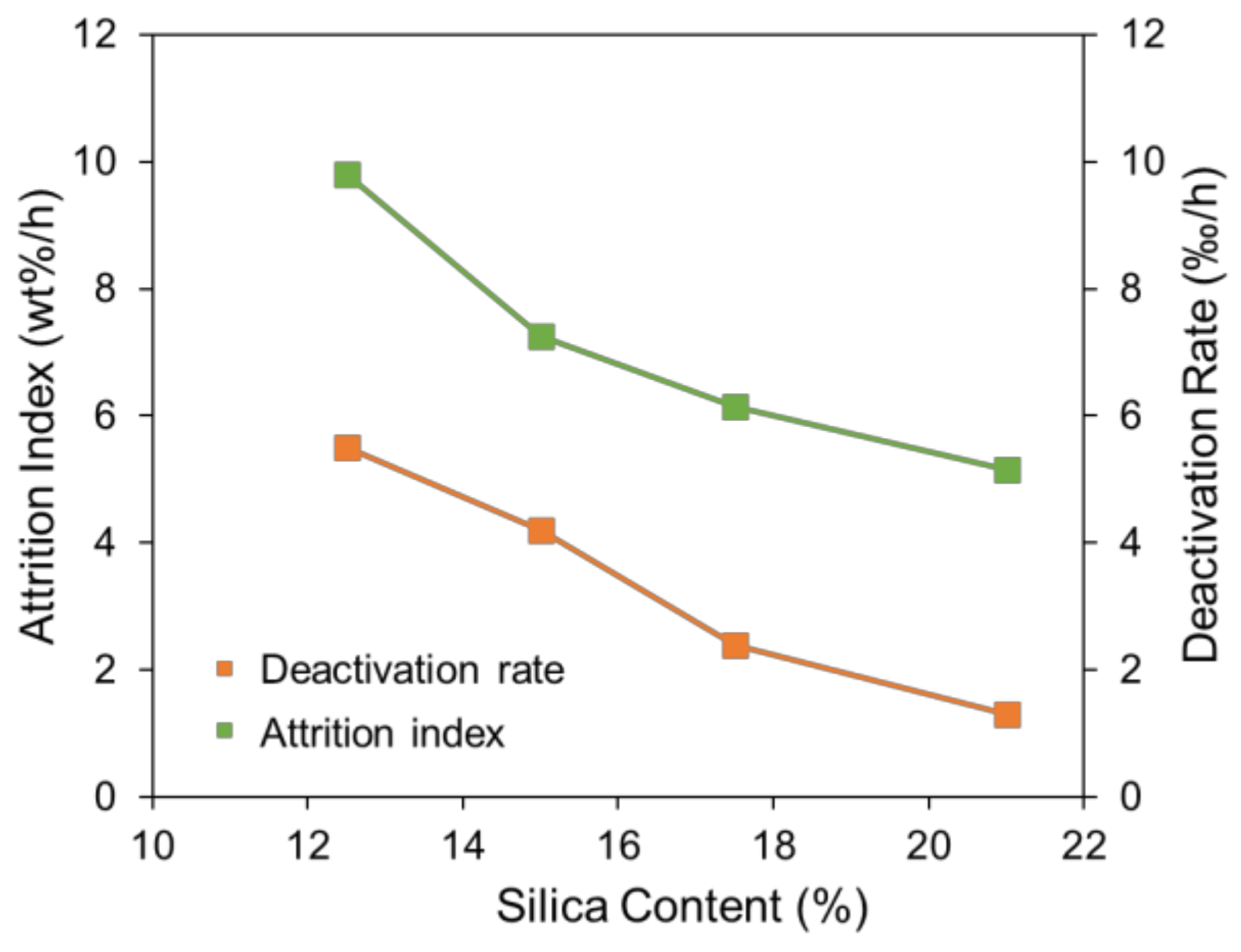
2.1. Effect of Silica Content on Attrition Resistance and Stability of Catalyst
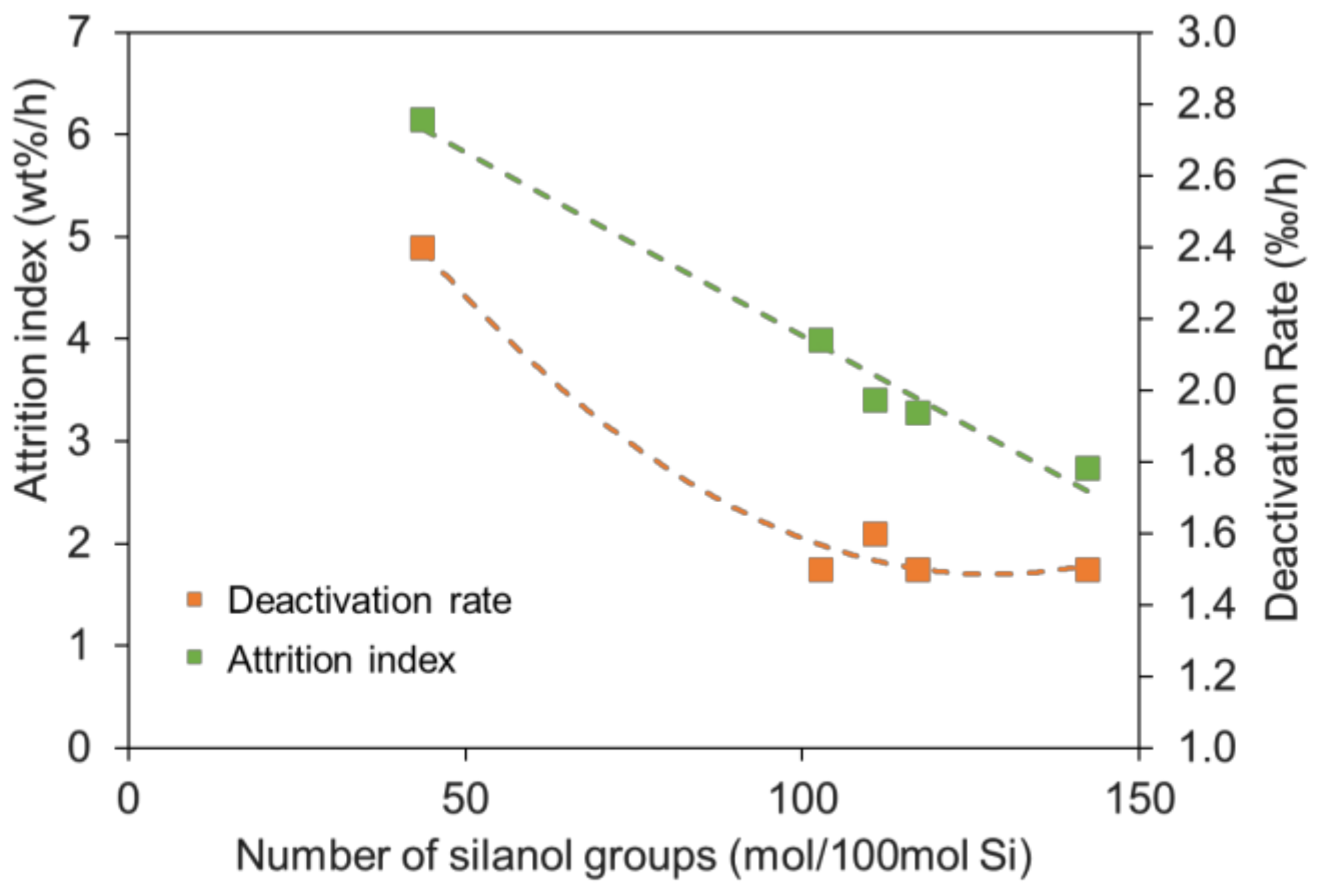
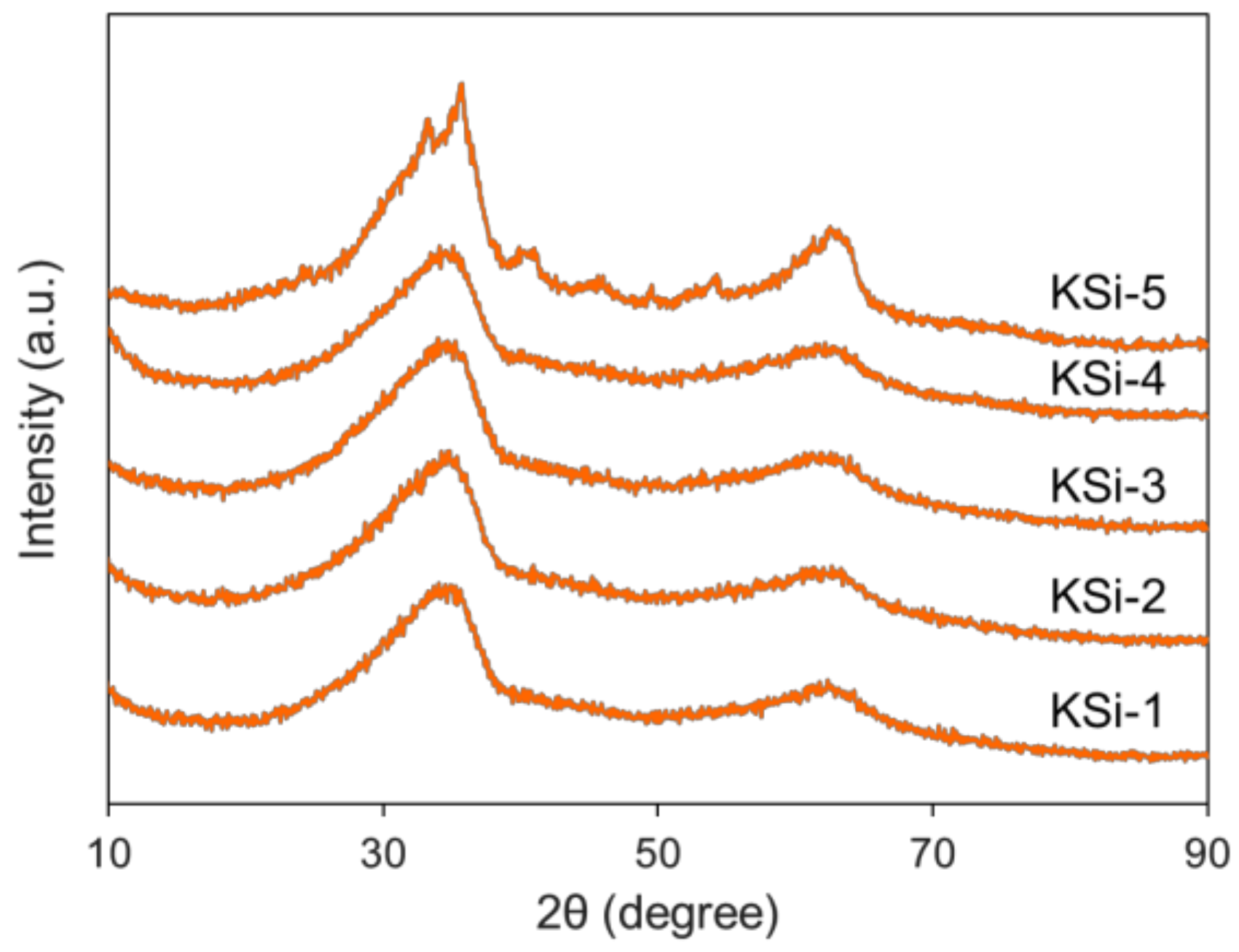
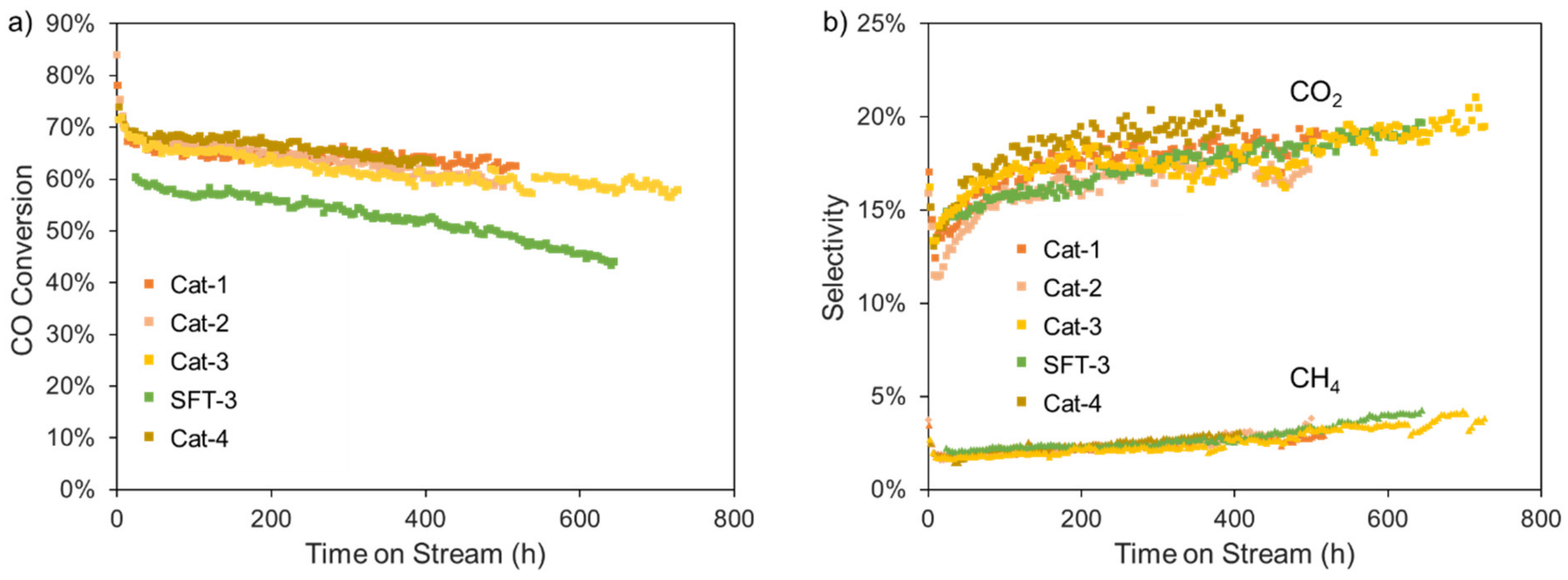
2.2. Effect of Silanol Content on Attrition Resistance and Stability of Catalyst
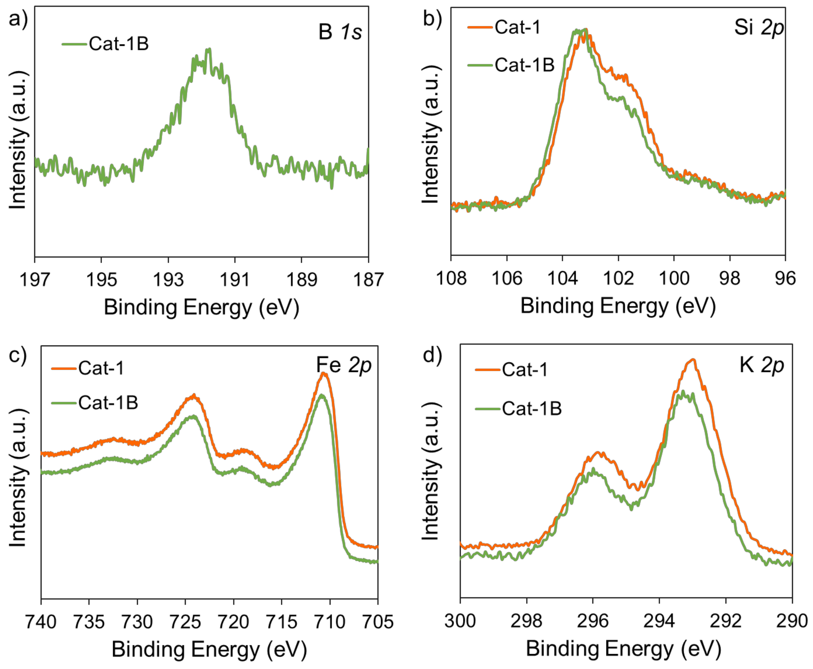
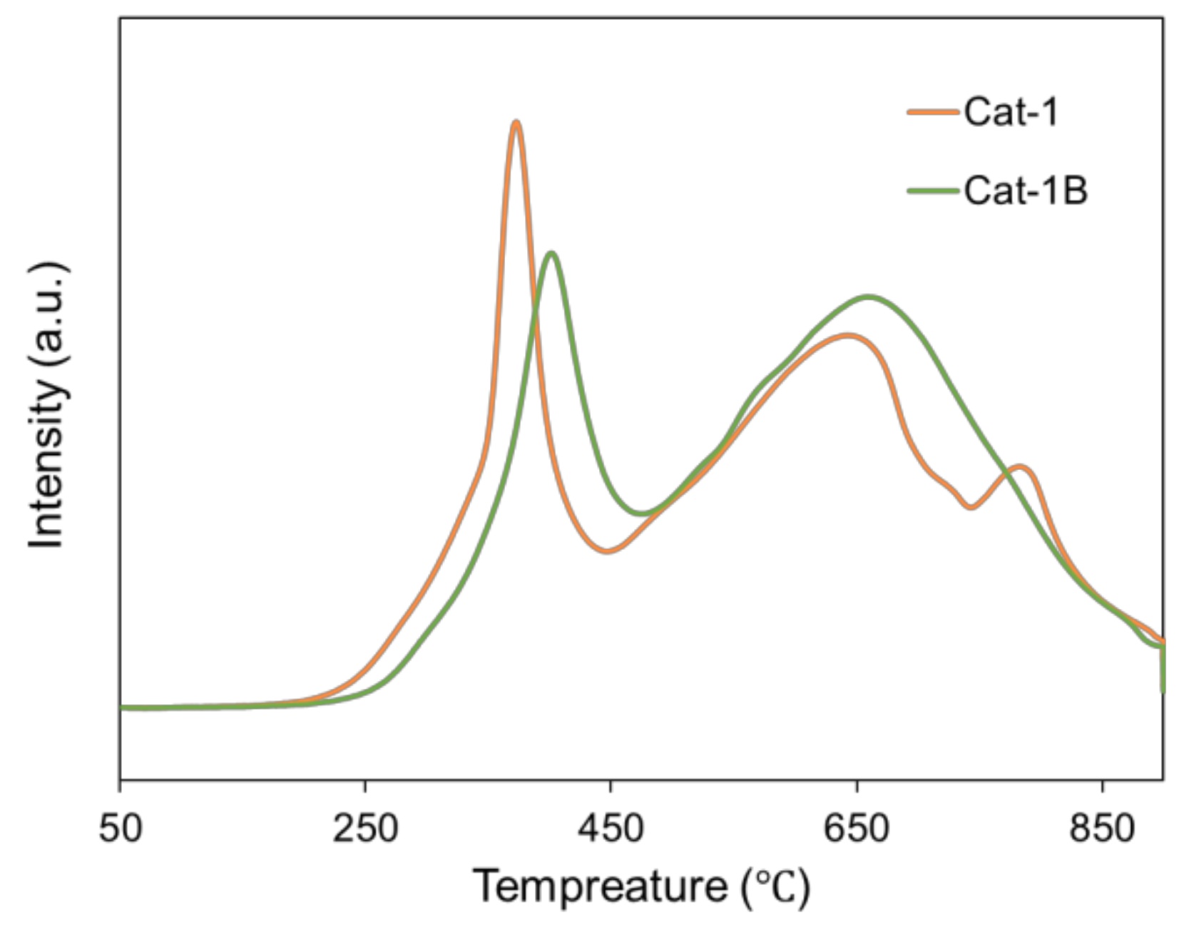
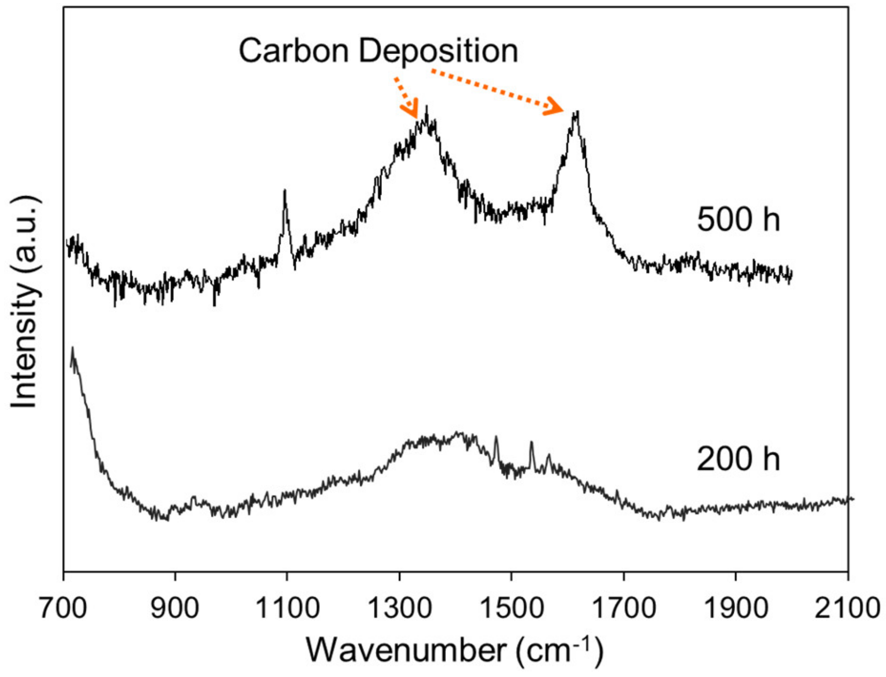
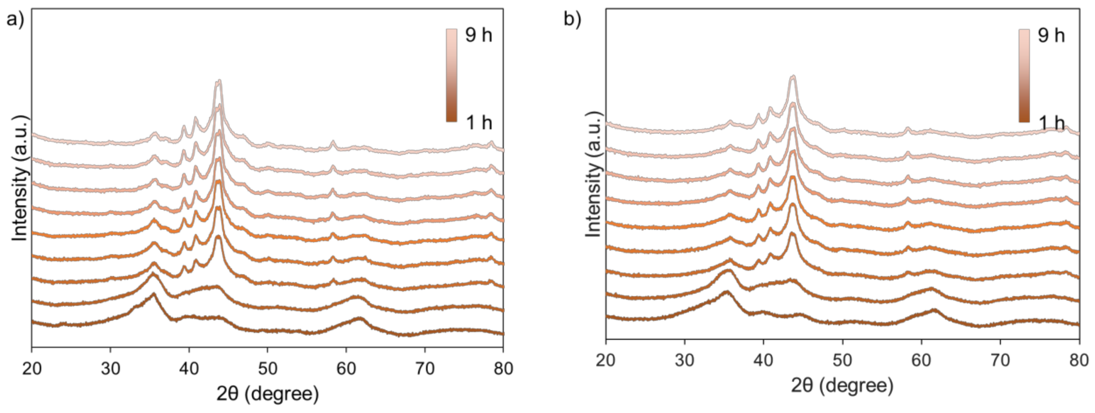
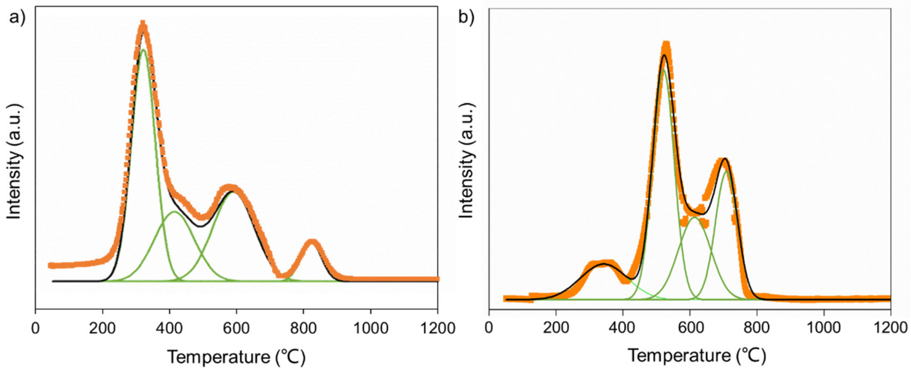
2.3. Anti-Carbon Deposition Formula Design
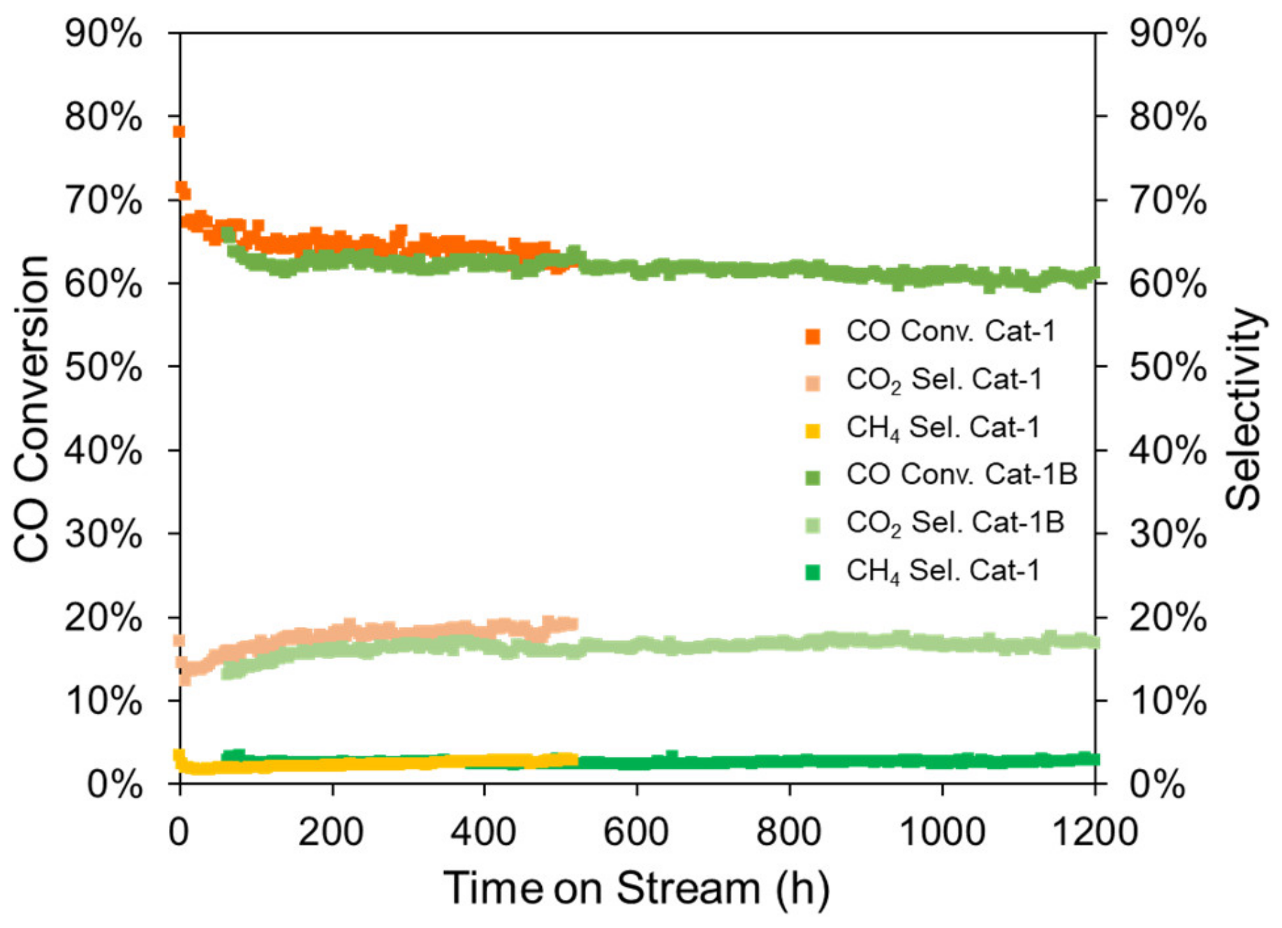
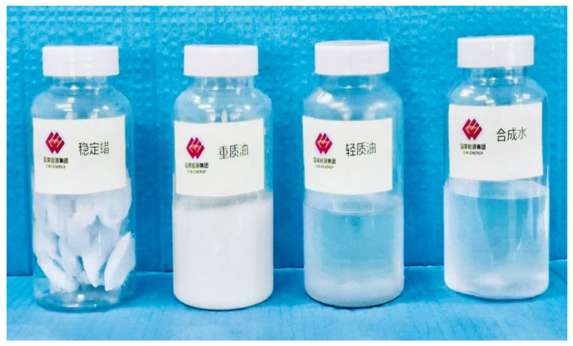
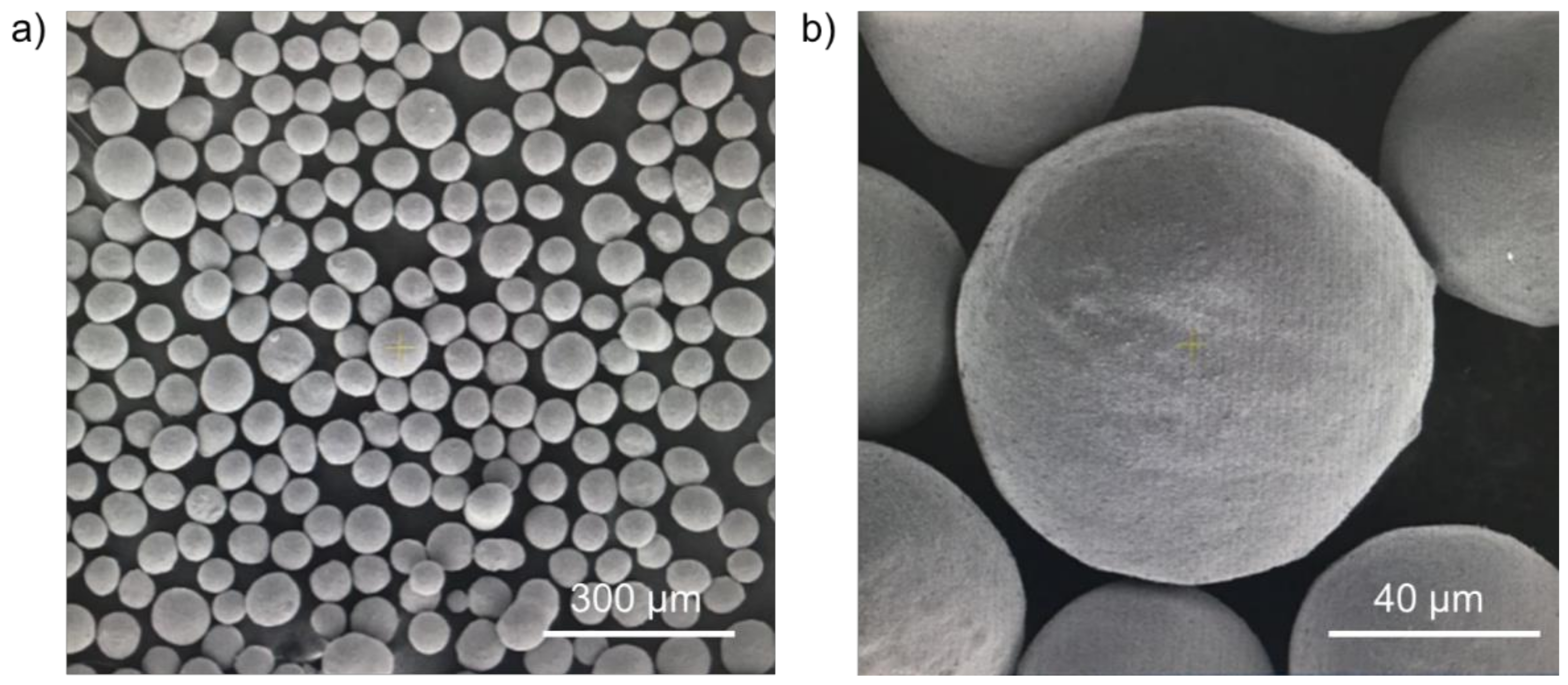
2.4. Industrial Application of Catalyst with Highly Attrition Resistant and Stability
3. Materials and Methods
3.1. Materials
3.2. Catalyst Preparation
3.3. Catalyst Characterization
3.3.1. Nitrogen Adsorption/Desorption
3.3.2. Nuclear Magnetic Resonance (NMR)
3.3.3. X-ray Diffraction
3.3.4. Scanning and Transmission Electron Microscopy
3.3.5. X-ray Photoelectron Spectroscopy (XPS)
3.3.6. Raman Spectrum
3.3.7. Temperature-Programmed Reduction (TPR)
3.3.8. Temperature-Programmed Hydrogenation (TPH)
3.3.9. H2-Thermogravimetric Analysis (H2-TGA)
3.3.10. Attrition Index
3.3.11. Attrition Test under Reactive FTS Conditions
3.4. Fischer–Tropsch Synthesis Performance Test
4. Conclusions
Author Contributions
Funding
Conflicts of Interest
References
- Dry, M.E. Fischer–Tropsch synthesis. In Catalysis, Science and Technology, 1st ed.; Anderson, J.R., Boudart, M., Eds.; Springer: New York, NY, USA, 1981; pp. 159–255. [Google Scholar]
- Van de Laan, G. Kinetics, Selectivity and Scale up of the Fischer–Tropsch Synthesis. Ph.D. Thesis, University of Groningen, Groningen, The Netherlands, 1999. [Google Scholar]
- Jager, B. Developments in Fischer–Tropsch technology. In Studies in Surface Science and Catalysis; Elsevier: Amsterdam, The Netherlands, 1997; Volume 107, pp. 219–224. [Google Scholar]
- Men, Z.W.; Lin, Q.; Lv, Y.J. The selection of the cobalt catalysts for Fischer–Tropsch synthesis. Shen Hua Sci. Technol. 2009, 7, 85–87. [Google Scholar]
- Kalakkad, D.S.; Shroff, M.D.; Köhler, S.; Jackson, N.; Datye, A.K. Attrition of precipitated iron Fischer–Tropsch catalysts. Appl. Catal. A Gen. 1995, 133, 335–350. [Google Scholar] [CrossRef]
- Pham, H.N.; Nowicki, L.; Xu, J.; Datye, A.K.; Bukur, D.B.; Bartholomew, C. Attrition Resistance of Supports for Iron Fischer–Tropsch Catalysts. Ind. Eng. Chem. Res. 2003, 42, 4001–4008. [Google Scholar] [CrossRef]
- Lin, T.-J.; Meng, X.; Shi, L. Attrition Studies of an Iron Fischer–Tropsch Catalyst Used in a Pilot-Scale Stirred Tank Slurry Reactor. Ind. Eng. Chem. Res. 2012, 51, 13123–13131. [Google Scholar] [CrossRef]
- Bukur, D.B.; Ma, W.-P.; Carreto-Vazquez, V. Attrition studies with precipitated iron Fischer–Tropsch catalysts under reaction conditions. Top Catal. 2005, 32, 135–141. [Google Scholar] [CrossRef]
- Bukur, D.B.; Carreto-Vazquez, V.; Pham, H.N.; Datye, A.K. Attrition properties of precipitated iron Fischer–Tropsch catalysts. Appl. Catal. A Gen. 2004, 266, 41–48. [Google Scholar] [CrossRef]
- Jager, B.; van Berge, P.; Steynberg, A.P. Developments in Fischer–Tropsch Technology and its Application. In Studies in Surface Science and Catalysis; Elsevier: Amsterdam, The Netherlands, 2001; Volume 136, pp. 63–68. [Google Scholar]
- Jager, B.; Espinoza, R. Advances in low temperature Fischer–Tropsch synthesis. Catal. Today 1995, 23, 17–28. [Google Scholar] [CrossRef]
- Zhao, R.; Goodwin, J.G.; Oukaci, R. Attrition assessment for slurry bubble column reactor catalysts. Appl. Catal. A Gen. 1999, 189, 99–116. [Google Scholar] [CrossRef]
- Bukur, D.B. Attrition studies with catalysts and supports for slurry phase Fischer–Tropsch synthesis. Catal. Today 2005, 106, 275–281. [Google Scholar] [CrossRef]
- Pham, H.N.; Datye, A.K. The synthesis of attrition resistant slurry phase iron Fischer–Tropsch catalysts. Catal. Today 2000, 58, 233–240. [Google Scholar] [CrossRef]
- Zhao, R.; Goodwin, J.G.; Jothimurugesan, K.; Gangwal, S.K.; Spivey, J.J. Spray-Dried Iron Fischer–Tropsch Catalysts. 1. Effect of Structure on the Attrition Resistance of the Catalysts in the Calcined State. Ind. Eng. Chem. Res. 2001, 40, 1065–1075. [Google Scholar] [CrossRef]
- Zhao, R.; Goodwin, J.G.; Jothimurugesan, K.; Gangwal, S.K.; Spivey, J.J. Spray-Dried Iron Fischer–Tropsch Catalysts. 2. Effect of Carburization on Catalyst Attrition Resistance. Ind. Eng. Chem. Res. 2001, 40, 1320–1328. [Google Scholar] [CrossRef]
- Sudsakorn, K.; Goodwin, J.G.; Jothimurugesan, K.; Adeyiga, A.A. Preparation of Attrition-Resistant Spray-Dried Fe Fischer–Tropsch Catalysts Using Precipitated SiO2. Ind. Eng. Chem. Res. 2001, 40, 4778–4784. [Google Scholar] [CrossRef]
- Bukur, D.B.; Carreto-Vazquez, V.H.; Ma, W. Catalytic performance and attrition strength of spray-dried iron catalysts for slurry phase Fischer–Tropsch synthesis. Appl. Catal. A Gen. 2010, 388, 240–247. [Google Scholar] [CrossRef]
- Hou, W.; Wu, B.; Yang, Y.; Hao, Q.; Tian, L.; Xiang, H.; Li, Y. Effect of SiO2 content on iron-based catalysts for slurry Fischer–Tropsch synthesis. Fuel Process. Technol. 2008, 89, 284–291. [Google Scholar] [CrossRef]
- Chang, H.; Cheng, M.; Lin, Q.; Zhu, J.Q.; Lv, Y.J.; Men, Z.W. Effects of binder addition process parameters on physical-chemical and catalytic performance of iron-based Fischer–Tropsch (F–T) synthesis catalyst. J. China Coal Soc. in press.
- Duvenhage, D.; Coville, N. Deactivation of a precipitated iron Fischer–Tropsch catalyst—A pilot plant study. Appl. Catal. A Gen. 2006, 298, 211–216. [Google Scholar] [CrossRef]
- Thüne, P.; Moodley, P.; Scheijen, F.; Fredriksson, H.; Lancee, R.; Kropf, J.; Miller, J.; Niemantsverdriet, J.W. The Effect of Water on the Stability of Iron Oxide and Iron Carbide Nanoparticles in Hydrogen and Syngas Followed by in Situ X-ray Absorption Spectroscopy. J. Phys. Chem. C 2012, 116, 7367–7373. [Google Scholar] [CrossRef]
- Xie, J.; Torres Galvis, H.M.; Koeken, A.C.J.; Kirilin, A.; Dugulan, A.I.; Ruitenbeek, M.; de Jong, K.P. Size and Promoter Effects on Stability of Carbon-Nanofiber-Supported Iron-Based Fischer–Tropsch Catalysts. ACS Catal. 2016, 6, 4017–4024. [Google Scholar] [CrossRef] [Green Version]
- Nakhaei Pour, A.; Housaindokht, M.R.; Tayyari, S.F.; Zarkesh, J.; Alaei, M.R. Deactivation studies of Fischer–Tropsch synthesis on nano-structured iron catalyst. J. Mol. Catal. A Chem. 2010, 330, 112–120. [Google Scholar] [CrossRef]
- Li, S.; Li, A.; Krishnamoorthy, S.; Iglesia, E. Effects of Zn, Cu, and K Promoters on the Structure and on the Reduction, Carburization, and Catalytic Behavior of Iron-Based Fischer–Tropsch Synthesis Catalysts. Catal. Lett. 2001, 77, 197–205. [Google Scholar] [CrossRef]
- Qing, M.; Yang, Y.; Wu, B.; Wang, H.; Wang, H.; Xu, J.; Zhang, C.; Xiang, H.; Li, Y. Effect of the zirconia addition manner on the modification of Fe–SiO2 interaction. Catal. Today 2012, 183, 79–87. [Google Scholar] [CrossRef]
- Dad, M. From 2D to 3D: Development, Characterization and Testing of a Well-Defined Fe-Mn/SiO2 Fischer–Tropsch Model Catalyst. Ph.D. Thesis, Eindhoven University of Technology, Eindhoven, The Netherlands, 2016. [Google Scholar]
- Zhang, Y.; Qing, M.; Wang, H.; Liu, X.-W.; Liu, S.; Wan, H.; Li, L.; Gao, X.; Yang, Y.; Wen, X.-D.; et al. Comprehensive understanding of SiO2-promoted Fe Fischer–Tropsch synthesis catalysts: Fe-SiO2 interaction and beyond. Catal. Today 2021, 368, 96–105. [Google Scholar] [CrossRef]
- Suo, H.; Zhang, C.; Wu, B.; Xu, J.; Yang, Y.; Xiang, H.; Li, Y. A comparative study of Fe/SiO2 Fischer–Tropsch synthesis catalysts using tetraethoxysilane and acidic silica sol as silica sources. Catal. Today 2012, 183, 88–95. [Google Scholar] [CrossRef]
- Arakawa, H.; Bell, A.T. Effects of potassium promotion on the activity and selectivity of iron Fischer–Tropsch catalysts. Ind. Eng. Chem. Proc. Des. Dev. 1983, 22, 97–103. [Google Scholar] [CrossRef]
- Dry, M. Factors influencing the formation of carbon on iron Fischer–Tropsch catalysts II. The effect of temperature and of gases and vapors present during Fischer–Tropsch synthesis. J. Catal. 1970, 17, 347–354. [Google Scholar] [CrossRef]
- Pendyala, V.R.R.; Graham, U.M.; Jacobs, G.; Hamdeh, H.H.; Davis, B.H. Fischer–Tropsch Synthesis: Morphology, Phase Transformation, and Carbon-Layer Growth of Iron-Based Catalysts. ChemCatChem 2014, 6, 1952–1960. [Google Scholar] [CrossRef]
- Zhang, C.-H.; Wan, H.-J.; Yang, Y.; Xiang, H.-W.; Li, Y.-W. Study on the iron–silica interaction of a co-precipitated Fe/SiO2 Fischer–Tropsch synthesis catalyst. Catal. Commun. 2006, 7, 733–738. [Google Scholar] [CrossRef]
- Cong, X.-D.; Kirkpatrick, R.J.; Diamond, S. 29Si MAS NMR spectroscopic investigation of alkali silica reaction product gels. Cem. Concr. Res. 1993, 23, 811–823. [Google Scholar] [CrossRef]
- Ouyang, R.; Liu, J.-X.; Li, W.-X. Atomistic theory of Ostwald ripening and disintegration of supported metal particles under reaction conditions. J. Am. Chem. Soc. 2013, 135, 1760–1771. [Google Scholar] [CrossRef]
- Wan, H.; Qing, M.; Wang, H.; Liu, S.; Liu, X.-W.; Zhang, Y.; Gong, H.; Li, L.; Zhang, W.; Song, C.; et al. Promotive effect of boron oxide on the iron-based catalysts for Fischer–Tropsch synthesis. Fuel 2020, 281, 118714. [Google Scholar] [CrossRef]
- Mekki, A.; Holland, D.; McConville, C.F.; Salim, M. An XPS study of iron sodium silicate glass surfaces. J. Non-Cryst. Solids 1996, 208, 267–276. [Google Scholar] [CrossRef]
- Mitchell, D.F.; Clark, K.B.; Bardwell, J.A.; Lennard, W.N.; Massoumi, G.R.; Mitchell, I.V. Film thickness measurements of SiO2 by XPS. Surf. Interface Anal. 1994, 21, 44–50. [Google Scholar] [CrossRef]
- Sayyed, B.A.; Chatterjee, A.K.; Kanetkar, S.M.; Badrinarayanan, S.; Date, S.K. Surface characterisation of an iron oxide catalyst (ethylbenzene → styrene): An xps study. J. Chem. Sci. 1985, 95, 291–295. [Google Scholar]
- Wu, B.; Tian, L.; Bai, L.; Zhang, Z.; Xiang, H.; Li, Y.W. Study on a new iron catalyst for slurry Fischer–Tropsch synthesis. Catal. Commun. 2004, 5, 253–257. [Google Scholar] [CrossRef]
- Xu, J.; Bartholomew, C.H. Temperature-programmed hydrogenation (TPH) and in situ Mössbauer spectroscopy studies of carbonaceous species on silica-supported iron Fischer–Tropsch catalysts. J. Phys. Chem. B 2005, 109, 2392–2403. [Google Scholar] [CrossRef]


| Sample | Si Content 1 (%) | Attrition Index (wt%/h) | BET Surface (m2/g) | Pore Volume (cm3/g) | Average Pore Size (nm) |
|---|---|---|---|---|---|
| SFT-1 | 12.5 | 9.8 | 179.0 | 0.54 | 12.0 |
| SFT-2 | 15.0 | 7.2 | 171.4 | 0.47 | 11.1 |
| SFT-3 | 17.5 | 6.2 | 180.2 | 0.56 | 11.6 |
| SFT-4 | 21.0 | 5.2 | 175.6 | 0.57 | 13.0 |
| Sample | Si Content 2 (%) | CO Conversion (%) | CO2 Selectivity (%) | CH4 Selectivity (%) | Deactivation Rate 3 (‰/h) | |||
|---|---|---|---|---|---|---|---|---|
| 200 h | 300 h | 200 h | 300 h | 200 h | 300 h | |||
| SFT-1 | 12.5 | 64.7 | 59.2 | 19.8 | 22.0 | 1.5 | 2.1 | 0.55 |
| SFT-2 | 15.0 | 63.6 | 59.4 | 17.5 | 19.0 | 1.9 | 2.3 | 0.42 |
| SFT-3 | 17.5 | 56.1 | 53.7 | 16.4 | 17.5 | 2.2 | 2.5 | 0.24 |
| SFT-4 | 21.0 | 45.8 | 44.5 | 14.6 | 14.8 | 3.0 | 3.1 | 0.13 |
| Sample | Si Content (%) | Fe2O3 → Fe3O4 | Fe3O4 → Fe | Total Reduction Degree (%) | ||||
|---|---|---|---|---|---|---|---|---|
| Peak Temp. (°C) | Weight Loss (%) | Reduction Degree (%) | Peak Temp. (°C) | Weight Loss (%) | Reduction Degree (%) | |||
| SFT-1 | 12.5 | 259.2 | 8.7 | 35.5 | 769.6 | 15.1 | 61.6 | 97.1 |
| SFT-2 | 15.0 | 267.0 | 8.3 | 33.9 | 715.0 | 14.4 | 58.6 | 92.6 |
| SFT-3 | 17.5 | 267.8 | 7.4 | 30.1 | 682.8 | 12.6 | 51.6 | 81.7 |
| SFT-4 | 21.0 | 275.4 | 7.8 | 31.7 | 654.0 | 8.6 | 35.0 | 66.7 |
| Sample | Fe Content in Liquid Products (ppm) | |
|---|---|---|
| After 30 min Deposit | After 60 min Deposit | |
| SFT-3 | 627 | 367 |
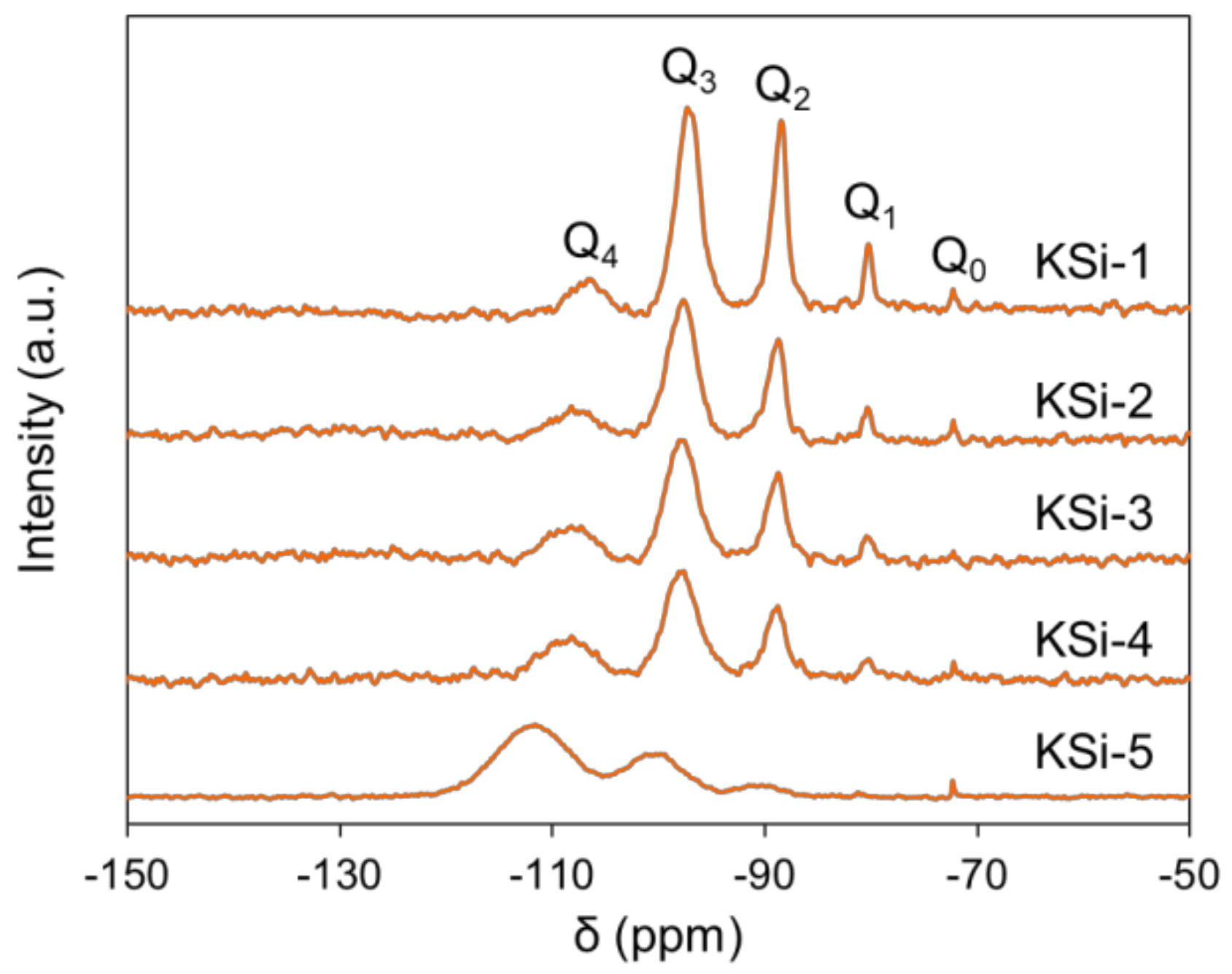
| Si Source | Q0 (%) | Q1 (%) | Q2 (%) | Q3 (%) | Q4 (%) | Silanol Content (mol/100 mol Si) |
|---|---|---|---|---|---|---|
| KSi-1 | 1.29 | 7.79 | 31.58 | 50.54 | 8.81 | 142 |
| KSi-2 | 0.68 | 3.15 | 24.39 | 56.10 | 15.68 | 117 |
| KSi-3 | 0.02 | 2.37 | 24.99 | 53.62 | 19.00 | 111 |
| KSi-4 | 0.92 | 3.30 | 20.30 | 48.42 | 27.06 | 103 |
| KSi-5 | 0.46 | 0.28 | 5.75 | 29.37 | 64.15 | 44 |
| Sample | Si Source | Attrition Index (wt%/h) | BET Surface (m2/g) | Pore Volume (cm3/g) | Average Pore Size (nm) |
|---|---|---|---|---|---|
| Cat-1 | KSi-1 | 2.7 | 171.3 | 0.49 | 11.7 |
| Cat-2 | KSi-2 | 3.3 | 169.5 | 0.45 | 13.4 |
| Cat-3 | KSi-3 | 3.4 | 170.0 | 0.47 | 11.5 |
| Cat-4 | KSi-4 | 4.0 | 167.5 | 0.48 | 11.9 |
| SFT-3 | KSi-5 | 6.1 | 180.2 | 0.56 | 11.6 |
| Sample 1 | Si Source | CO Conversion (%) | CO2 Selectivity (%) | CH4 Selectivity (%) | Deactivation Rate 2 (‰/h) |
|---|---|---|---|---|---|
| Cat-1 | KSi-1 | 64.9 | 17.6 | 2.2 | 0.15 |
| Cat-2 | KSi-2 | 64.1 | 15.8 | 2.2 | 0.15 |
| Cat-3 | KSi-3 | 64.5 | 17.4 | 2.2 | 0.16 |
| Cat-4 | KSi-4 | 66.2 | 19.5 | 2.4 | 0.15 |
| SFT-3 | KSi-5 | 56.1 | 16.4 | 2.2 | 0.24 |
| Sample | Fe Content in Liquid Products (ppm) | |
|---|---|---|
| After 30 min Deposit | After 60 min Deposit | |
| Cat-1 | 22 | 20 |
| Time (h) | 3 | 4 | 5 | 6 | 7 | 8 | 9 |
|---|---|---|---|---|---|---|---|
| Cat-1 grain size (nm) | 12.8 | 18.2 | 20.4 | 19.1 | 21.6 | 20.4 | 21.7 |
| Cat-1B grain size (nm) | 12.2 | 14.9 | 15.9 | 16.2 | 15.9 | 15.2 | 15.5 |
| Sample | Content of Carbon Species (%) | |||
|---|---|---|---|---|
| α | β | γ | δ | |
| Cat-1 | 6.4 | 44.0 | 40.8 | 8.8 |
| Cat-1B | 43.2 | 21.6 | 28.8 | 6.4 |
| Sample | Si Source | Attrition Index (wt%/h) | BET Surface (m2/g) | Pore Volume (cm3/g) | Average Pore Size (nm) |
|---|---|---|---|---|---|
| Cat-1 | KSi-1 | 2.7 | 171.2 | 0.49 | 11.7 |
| Cat-1B | KSi-1 | 2.4 | 143.2 | 0.47 | 13.3 |
| Sample 1 | Si Source | CO Conversion (%) | CO2 Selectivity (%) | CH4 Selectivity (%) | Deactivation Rate 1 (‰/h) |
|---|---|---|---|---|---|
| Cat-1 | KSi-1 | 64.9 | 17.6 | 2.2 | 0.15 |
| Cat-1B | KSi-1 | 62.4 | 16.0 | 2.5 | 0.012 |
| Item | Value |
|---|---|
| Total CO conversion (mol%) | 97.4 |
| CO2 selectivity (mol%) | 2.0 |
| CH4 selectivity (mol%) | 18.8 |
| Syngas consumption per ton oil (Nm3/t) | 5631 |
| Wax/oil ratio (t/t) | 1.4 |
Publisher’s Note: MDPI stays neutral with regard to jurisdictional claims in published maps and institutional affiliations. |
© 2021 by the authors. Licensee MDPI, Basel, Switzerland. This article is an open access article distributed under the terms and conditions of the Creative Commons Attribution (CC BY) license (https://creativecommons.org/licenses/by/4.0/).
Share and Cite
Lin, Q.; Cheng, M.; Zhang, K.; Li, W.; Wu, P.; Chang, H.; Lv, Y.; Men, Z. Development of an Iron-Based Fischer—Tropsch Catalyst with High Attrition Resistance and Stability for Industrial Application. Catalysts 2021, 11, 908. https://doi.org/10.3390/catal11080908
Lin Q, Cheng M, Zhang K, Li W, Wu P, Chang H, Lv Y, Men Z. Development of an Iron-Based Fischer—Tropsch Catalyst with High Attrition Resistance and Stability for Industrial Application. Catalysts. 2021; 11(8):908. https://doi.org/10.3390/catal11080908
Chicago/Turabian StyleLin, Quan, Meng Cheng, Kui Zhang, Weizhen Li, Peng Wu, Hai Chang, Yijun Lv, and Zhuowu Men. 2021. "Development of an Iron-Based Fischer—Tropsch Catalyst with High Attrition Resistance and Stability for Industrial Application" Catalysts 11, no. 8: 908. https://doi.org/10.3390/catal11080908
APA StyleLin, Q., Cheng, M., Zhang, K., Li, W., Wu, P., Chang, H., Lv, Y., & Men, Z. (2021). Development of an Iron-Based Fischer—Tropsch Catalyst with High Attrition Resistance and Stability for Industrial Application. Catalysts, 11(8), 908. https://doi.org/10.3390/catal11080908